EP3636520B1 - Dispositif de ballastage et véhicule agricole - Google Patents
Dispositif de ballastage et véhicule agricole Download PDFInfo
- Publication number
- EP3636520B1 EP3636520B1 EP19197281.9A EP19197281A EP3636520B1 EP 3636520 B1 EP3636520 B1 EP 3636520B1 EP 19197281 A EP19197281 A EP 19197281A EP 3636520 B1 EP3636520 B1 EP 3636520B1
- Authority
- EP
- European Patent Office
- Prior art keywords
- ballasting
- arm
- ballast
- bearing
- adjustable
- Prior art date
- Legal status (The legal status is an assumption and is not a legal conclusion. Google has not performed a legal analysis and makes no representation as to the accuracy of the status listed.)
- Active
Links
Images



Classifications
-
- B—PERFORMING OPERATIONS; TRANSPORTING
- B62—LAND VEHICLES FOR TRAVELLING OTHERWISE THAN ON RAILS
- B62D—MOTOR VEHICLES; TRAILERS
- B62D49/00—Tractors
- B62D49/08—Tractors having means for preventing overturning or tipping
- B62D49/085—Counterweight
-
- B—PERFORMING OPERATIONS; TRANSPORTING
- B62—LAND VEHICLES FOR TRAVELLING OTHERWISE THAN ON RAILS
- B62D—MOTOR VEHICLES; TRAILERS
- B62D49/00—Tractors
- B62D49/06—Tractors adapted for multi-purpose use
- B62D49/0621—Tractors adapted for multi-purpose use comprising traction increasing arrangements, e.g. all-wheel traction devices, multiple-axle traction arrangements, auxiliary traction increasing devices
- B62D49/0628—Tractors adapted for multi-purpose use comprising traction increasing arrangements, e.g. all-wheel traction devices, multiple-axle traction arrangements, auxiliary traction increasing devices using detachable weights
-
- B—PERFORMING OPERATIONS; TRANSPORTING
- B62—LAND VEHICLES FOR TRAVELLING OTHERWISE THAN ON RAILS
- B62D—MOTOR VEHICLES; TRAILERS
- B62D37/00—Stabilising vehicle bodies without controlling suspension arrangements
- B62D37/04—Stabilising vehicle bodies without controlling suspension arrangements by means of movable masses
Definitions
- the invention relates to a ballasting device for an agricultural vehicle and an agricultural vehicle with a ballasting device.
- ballasting devices or weights are usually arranged and permanently installed at a predetermined location on the front and / or rear part of the vehicle body. It is often associated with considerable effort and cannot be implemented without complex equipment (forklift truck, crane, lifting device, etc.) to assemble or dismantle the ballast devices or weights.
- ballast weights or ballast devices offer only a few and / or complex options for varying the ballast or the additional load applied to the front axle by ballasting and / or adapting it to changing circumstances or working conditions. In practice, this often means that the same ballast weight is usually used and the agricultural vehicle is therefore not optimally ballasted. This can also lead to further disadvantages, for example higher fuel consumption and / or a higher risk potential in road traffic.
- the EP 2 186 713 A2 discloses an adjustable ballasting device on an agricultural vehicle, wherein the ballasting device can be picked up by the lower links of a three-point hitch.
- pivoting means are provided, by means of which the ballasting device can be pivoted about a pivot axis and adjusted in the longitudinal direction of the vehicle.
- the ballast weight is here in a recorded state of the ballast device in relation to a distance of the center of gravity of the ballast device from the vehicle between a distance close to the vehicle Movable position and a position remote from the vehicle.
- the solutions known from the prior art, in particular those in FIG EP 2 186 713 A2 disclosed ballasting device have the disadvantages already mentioned.
- the object on which the invention is based is thus seen in proposing a ballasting device and an agricultural vehicle by means of which the aforementioned problems and / or disadvantages are at least partially overcome.
- the object on which the invention is based is to propose a ballasting device and an agricultural vehicle by means of which the center of gravity of the ballasting device can be changed and / or adapted to the changing working conditions and / or the potential danger in road traffic is reduced and / or structurally simple is designed.
- a ballast device for an agricultural vehicle with a ballast body and a first ballast arm and a second ballast arm is proposed.
- One end of the first ballast arm is pivotably mounted on the ballast body about a first bearing axis and a first ballast weight is arranged, in particular releasably connected or fastened, at the other end of the first ballast arm.
- One end of the second ballasting arm is also pivotably mounted on the ballasting body about a second bearing axis and a second ballasting weight is arranged, in particular releasably connected or fastened, at the other end.
- the ballasting device in particular the ballasting body, has a receiving device for receiving the ballasting device by means of a three-point hitch of the agricultural vehicle.
- the first ballast weight is adjustable, preferably adjustable and / or pivotable, by means of the first ballast arm and the second ballast weight is adjustable by means of the second ballast arm.
- the first and second ballasting arms and thus the first and second ballasting weights can be pivoted relative to one another or, in other words, the first and second ballasting weights can be pivoted relative to one another by means of the first and second ballasting arms.
- first and second Ballast weight relative to one another and / or in relation to the ballast body by means of the first and / or second ballast arm can be adjusted, preferably adjustable and / or pivotable, particularly preferably pivotable relative to one another.
- the first and / or second ballasting arm can in particular be elongated, that is to say have an extension essentially along the respective longitudinal axis of the first and / or second ballasting arm.
- the geometry and / or the structure of the first and second ballasting arms can be the same.
- One end of the first ballast arm for example a first end, is mounted on the ballast body so as to be pivotable about the first bearing axis, so one end can be articulated to the ballast body.
- One end of the second ballast arm for example a first end, is mounted on the ballast body so as to be pivotable about the second bearing axis, so one end can also be hinged to the ballast body.
- the first ballast weight is arranged at the respective other end, for example a respective second end, of the first ballasting arm and the second ballasting weight is arranged on the second ballasting arm.
- the ballast device can be picked up on the pick-up device by the three-point hitch.
- the receiving device can have one, two or more receiving elements, for example receiving bolts, and / or a receiving bearing.
- the receiving element can be received by a lower link of the three-point hitch and / or can be pivotably coupled to the three-point hitch, in particular the receiving element can be aligned coaxially with a pivot axis.
- the mounting bearing can be accommodated by an upper link of the three-point hitch and / or can be coupled to the upper link, in particular pivotably coupled to the upper link.
- the receiving bearing can preferably be a steering plate, in particular a triangular steering plate, which has two opposite steering plate sides.
- the upper link can extend between the two steering plate halves and be linked to them, for example by means of a bolt or pin.
- the receiving device in particular the receiving element and / or the receiving bearing, can be detachably connected to the ballast body or fastened to the ballast body or be designed as a part of the ballast body.
- the ballast body and the receiving device, in particular the receiving element and / or the receiving bearing, can be designed in one piece.
- the receiving device can have two Include mounting elements, which can be designed as two mounting bolts arranged laterally (laterally in the sense of transversely to a vehicle longitudinal axis) on the ballast body, and which can be picked up and / or pivoted to the three-point hitch by two lower links of the three-point hitch.
- the pivot axis is defined by the two lateral locating pins, which are held by the lower links of the three-point hitch.
- the locating pins can be aligned coaxially to the common pivot axis.
- the three-point hitch can in particular be a three-point power lift, which can be designed, for example, as a rear linkage on the rear of the agricultural vehicle and / or a front linkage on the front of the agricultural vehicle.
- the ballasting device can be received by the lower links and the upper link, in particular a length-invariant upper link, of the three-point hitch and / or can be pivoted and / or coupled to the articulation points of the lower link and / or the upper link.
- the top link can also be a length-adjustable top link, in particular such that a change in length of the top link enables the ballasting device to pivot, in particular about the pivot axis.
- the first ballasting weight by means of the first ballasting arm and the second ballasting weight are adjustable, preferably adjustable and / or pivotable by means of the second ballasting arm, such that the center of gravity of the ballasting device, in particular a center of gravity and / or a distance of the Focus of the ballast device in relation to the ballast body, adjustable and / or adjustable.
- the first and second ballast weights can be pivoted relative to one another by means of the first and second ballast arms in such a way that the center of gravity of the ballast device, in particular a position of the center of gravity and / or a distance between the center of gravity of the ballast device in relation to the ballast body, is adjustable and / or adjustable.
- the adjustment or the pivoting movement of the first and / or second ball bull arm can take place manually, for example by means of human strength, or in an automated manner.
- the first and second ballasting arms can be adjusted, preferably adjusted, from an open position, in which the center of gravity of the ballasting device has no or a minimal distance from the ballasting body, into a closed position, in which the center of gravity of the ballasting device is at a maximum distance from the ballasting body or be pivotable, particularly preferably pivotable relative to one another, and vice versa.
- the first and second ballasting arms In the open position, can be aligned parallel and / or coaxially to the pivot axis, so that the first and second ballasting weights are arranged diametrically to one another.
- the first and second ballasting arms can be aligned parallel to one another, in particular orthogonally to the pivot axis.
- the first and second ballast weights can therefore be arranged directly adjacent to one another.
- the first and second ballasting arms can also assume any position between the open position and the closed position, so that the center of gravity of the ballasting device can be adjusted.
- the first and second ballasting arms can therefore include an angle of 180 degrees in the open position and an angle of 0 degrees in the closed position, the first ballasting arm with its pivoting movement an angular range of 0 to 90 degrees and the second ballasting arm with its pivoting movement an angular range can sweep from 90 to 180 degrees.
- the ballasting device can be moved from a position close to the vehicle in relation to the center of gravity of the ballasting device to a position remote from the vehicle and vice versa.
- the ballasting device can be moved by lowering or raising the ballasting device with the lower links of the three-point hitch.
- the center of gravity of the ballasting device can be adjusted and / or set in relation to the vehicle, in particular in relation to a distance between the center of gravity of the ballasting device and the vehicle.
- the adjustment and / or setting of a center of gravity of the center of gravity of the ballasting device can thus advantageously be combined with the adjustment and / or setting of a center of gravity of the center of gravity of the ballasting device in relation to the vehicle.
- a rotational movement of the ballasting device about the pivot axis can be initiated.
- the center of gravity of the ballasting device can be shifted at a fixed distance from the pivot axis.
- the receiving bearing of the ball bull device can be designed in such a way that an upper link, in particular a length-adjustable upper link, of the three-point hitch can be coupled to it.
- a rotational movement of the ballasting device about the pivot axis can be set, in particular by adjusting the length of the A targeted rotational movement of the ballasting device around the pivot axis can be initiated via the top link.
- ballasting device thus has the following advantages. Simply because the center of gravity of the ballasting device is adjustable and / or adjustable, ballasting of the vehicle, that is to say an additional mass acting on the vehicle, can advantageously be set and / or varied very precisely.
- the ballasting device can thus advantageously be adapted to the prevailing operating and / or working conditions in a simple manner and / or quickly. Furthermore, when the ballasting device is in the picked-up state, it is also possible to adjust and / or set the center of gravity of the ballasting device in relation to the vehicle.
- Adjusting and / or setting a center of gravity of the center of gravity of the ballasting device in relation to the ballasting device itself can thus be combined with adjusting and / or setting a center of gravity of the center of gravity of the ballasting device in relation to the vehicle.
- the ballasting device in combination with the recorded state of the ballasting device thus enables several centers of gravity to be advantageously combined, whereby the additional mass acting on the vehicle can be set very precisely and / or adapted to the prevailing working and / or operating conditions.
- the first and second bearing axes are arranged parallel or spatially coinciding with one another. Furthermore, the first and second bearing axes can be arranged orthogonally to the pivot axis. If the first and second bearing axes are arranged spatially coinciding with one another, then the first and second ballasting arms can be mounted on the ballasting body so as to be pivotable about a common axis of rotation. In this case of the common axis of rotation, the first and second ballasting arms can be arranged one after the other or one above the other, that is to say sequentially, along the common axis of rotation. In this way, the ballast body can advantageously be designed to be smaller and the ballast arms can be designed to be longer.
- the first and second ballasting arms can be mounted on the ballasting body so as to be pivotable about the first and second bearing axes, that is to say two separate bearing axes, with parallel alignment. In this way, the weight of the first and second ballast weights can advantageously be better distributed on the ballast body.
- the ballasting device comprises a first bearing device for mounting the first ballasting arm on the ballasting body and / or a second bearing device for mounting the second ballasting arm on the ballasting body.
- the first ballast arm can be adjustably, preferably pivotably, mounted on the ballast body at the first end of the first ballast arm, in particular also articulated on the ballast body and / or coupled to the ballast body.
- the second ballast arm can be adjustably, preferably pivotably, mounted on the ballast body by means of the second bearing device at the first end of the second ballast arm, in particular also articulated on the ballast body and / or coupled to the ballast body.
- the first and second bearing device can also be designed as a common bearing device for the common bearing of the first and second ballast arm on the ballast body, that is, the first and second ballast arm can be adjustably, preferably pivotably, mounted on the ballast body at their respective first end by means of the common bearing device be, in particular articulated on the ballast body and / or coupled to the ballast body.
- the first bearing device can comprise a first fastening element and / or a first holding element and the second bearing device can comprise a second fastening element and / or a second holding element.
- the common bearing device can comprise a common fastening element or a first and second fastening element and a common holding element or a first and second holding element.
- the first and / or the second ballasting arm can each have a through hole at their respective first end.
- the first and / or second or common fastening element can be, for example, a pin and / or a bolt and / or a screw with a nut.
- the first and / or second holding element or the common holding element and the ballast body can be designed in one piece or as a component attached to the ballast body. If the first and second bearing axes are arranged spatially parallel to one another, the first fastening element can be designed as a first bearing axis and the second fastening element as a second bearing axis.
- the first ballast arm can then be adjustably mounted on the ballast body by means of the first fastening element, in particular articulated to the ballast body by means of the first fastening element, preferably by guiding the first fastening element through the through hole of the first ballast arm and the first holding element or the common holding element and the first fastening element on the Ballast body is locked or fastened.
- the second ballast arm can be adjusted by means of the second fastening element Ballast bodies are stored, preferably in that the second fastening element is guided through the through hole of the second ballast arm and the second holding element or the common holding element and the second fastening element is locked or fastened to the ballast body.
- the common fastening element can be designed as the common axis of rotation.
- the first and second ballast arm can then also be adjustably supported on the ballast body by means of the common fastening element or articulated to the ballast body by means of the common fastening element, preferably by guiding the common fastening element through the through bores of the first and second ballast arm and the common holding element and the common fastening element is locked or attached to the ballast body.
- the first and / or second holding element can, however, also be designed as a component of the ballasting device that is independent of the ballasting body and / or the ballasting arms.
- the first ballasting arm can be arranged on or in the first holding element and the second ballasting arm on or in the second holding element, preferably the ballasting arms can be detachably connected to or attached to the respective holding element.
- the first holding element with the first ballast arm arranged on or in the first holding element can be adjustably, in particular pivotably, mounted on the ballast body and / or coupled to the ballast body by means of the first fastening element.
- the second holding element with the second ballast arm arranged on or in the second holding element can be adjustably, in particular pivotably, mounted on the ballast body and / or coupled to the ballast body by means of the second fastening element.
- the first fastening element can be guided through the through-hole of the first ballasting arm and / or the first holding element.
- the second fastening element can be guided through the through hole of the second ballasting arm and / or the second holding element.
- the first and / or second fastening element can be locked or detachably connected or fastened to the ballast body.
- operatively connected can in particular be understood to mean the transmission of force between two components of the ballasting device, for example from the first to the second holding element or from the first to the second ballasting arm or from the first to the second active element and vice versa.
- a movement of the two components can thereby be synchronized.
- the first and / or second ballasting arm and / or the first and / or second holding element can be operatively connected to one another.
- the first and second ballasting arm and / or the first and second holding element can be operatively connected to one another by means of a connecting element, for example a lever.
- the connecting element can in particular be designed and arranged in such a way that the movement, in particular the pivoting movement, of the first and second holding element and / or of the first and second ballasting arm is thereby advantageously synchronized.
- the first ballasting arm comprises a first active element at one end, that is the first end, and the second ballasting arm, at one end, that is the first end, a second active element, the first and second active elements being operatively connected to one another.
- the first and / or second active element can be, for example, a toothed wheel or a belt connection.
- the first ballasting arm and the first active element and / or the second ballasting arm and the second active element can be designed in one piece, that is to say as one component, or in two pieces, in particular can be detachably connected to one another.
- the first and second active elements can in particular be operatively connected and / or arranged in such a way that the first and second ballasting arms can be adjusted, in particular pivoted relative to one another, by means of a movement of the first and / or second active element.
- the movement, in particular the pivoting movement, of the first and second ballasting arm can thereby advantageously be synchronized.
- the ballasting device comprises a first actuator with which the first ballasting arm is adjustable, in particular pivotable, about the first bearing axis, and / or the ballasting device comprises a second actuator, with which the second ballasting arm is adjustable, in particular pivotable, about the second bearing axis .
- the first actuator can be operatively connected to the first and / or second ballasting arm and / or the first and / or second holding element and / or the first and / or second active element and / or detachably coupled to them or fastened to them.
- the first and / or second ballasting arm and / or the first and / or second holding element and / or the first and / or second active element can be actuated and / or adjustable by means of the first actuator, preferably pivotable, in particular preferably be pivotable or movable relative to one another.
- the first actuator can thus advantageously also be used as a connecting element.
- a force, in particular a movement or pivoting movement, of the first actuator due to an existing operative connection from the first ballasting arm and / or first holding element and / or connecting element and / or first active element to the second ballasting arm and / or the second holding element and / or the second Active element are transferred.
- the first actuator and / or second actuator can be designed and arranged as described in such a way that they can move the first and second ballasting arms from the closed position into the open position and vice versa.
- the second actuator can be operatively connected to the second ballasting arm and / or the second holding element and / or the second active element and / or coupled and / or fastened to them.
- the second ballasting arm and / or the second holding element and / or the second active element can be actuated and / or adjustable, in particular pivotable, by means of the second actuator, ie the second actuator can exert a force such that the second ballasting arm and / or the first Holding element and / or the first active element can be actuated and / or adjusted.
- first and a second actuator can also be a force, in particular a movement or pivoting movement, of the second actuator and / or the second ballasting arm and / or the second holding element and / or the connecting element and / or the second active element due to the operative connection on the first ballasting arm and / or the first Retaining element and / or the first active element are transferred.
- a first and a second actuator are provided, it is also possible to dispense with a coupling, in particular an operative connection, between the ballast arms and / or holding elements and / or operative elements, in particular the connecting element can be dispensed with.
- the first and / or second actuator can preferably be designed as hydraulic cylinders.
- the first and / or second actuator can thus be designed as an electric motor, for example a spindle motor.
- a corresponding arrangement with a cable pull is also conceivable in order to make the actuation purely mechanical.
- the first and / or second actuator are preferably releasably connected and / or fastened to the first end of the respective ballasting arm and / or the respective holding element and / or the respective active element in such a way that, by actuating the first and / or second actuator, the first and / or the second ballasting arm can trigger a guided pivoting movement of the respective ballasting weight about the first and / or second bearing axis.
- This ensures that an operator can be remotely controlled realize a variation or displacement or adjustment of the ballasting device and can react quickly and optimize the ballasting even when operating conditions change.
- the ballast device or the agricultural vehicle can also comprise a control unit.
- the control unit can be designed and set up in such a way that the first and / or second ballasting arm or the first ballasting arm can be adjusted by means of the first actuator and / or the second ballasting arm by means of the second actuator, in particular pivotable relative to one another, in such a way that the center of gravity of the ballasting device can be determined and / or can be stored and / or output and / or adjusted.
- a method for adjusting and / or setting the center of gravity of the ballasting device can also be carried out with the control unit.
- the ballasting device comprises one or more stop buffers and / or one or more locking devices.
- One or more stop buffers and / or one or more fastening elements can be provided on the ballast body and / or the first and / or second ballast arm and / or the first and / or second ballast weight.
- the stop buffer can be designed as part of the ballast body and / or the first and / or second ballast arm and / or the first and / or second ballast weight and / or attached as a separate stop buffer.
- the stop buffer can be designed as a limit stop so that the pivoting movement of the first and / or second ballasting arm between the open position and the closed position is limited.
- the stop buffer can also be designed as a damper, so that the pivoting movement of the first and / or second ballast arm is damped.
- the stop buffers can be made of metal and / or an elastic material, for example iron and / or rubber.
- the stop buffer advantageously makes it possible to restrict the pivoting movement of the ballasting arms and / or to absorb kinetic energy of the ballasting arms.
- the ballast arms can be locked in the open and / or closed position or in other adjustable positions in between.
- the locking devices advantageously make it possible for the first and / or second ballasting arm not to be able to execute a pivoting movement.
- the locking device can for example comprise a first and / or second locking element, for example a pin and / or a bolt and / or a screw.
- first and / or second ballast arm can be locked precisely in the open position or the closed position by the first and / or second locking element with the ballast body and the respective ballast arms be releasably connected so that a pivoting movement of the ballast arms is blocked.
- the locking device can also include one or more hooks or bolts that lock the first and / or second ballast arm precisely in the open position or the closed position, for example by attaching the hook or bolt to the ballast body and with a counterpart, for example an eyelet, on the respective ballast arm is brought into a form-fitting and releasable connection so that a pivoting movement of the ballast arms is prevented.
- the hooks or latches may include springs to hold them in the ballast arms.
- the locking device can in particular be designed as a bonnet lock or snap lock.
- a locking device can be provided with which the lower and / or the upper link of the three-point hitch can be locked in the adjustable positions.
- the locking device preferably comprises that the first and / or second ballast arm and / or the locking device, that the adjustable lower and / or the adjustable upper link can be locked hydraulically or pneumatically or mechanically or electrically in a certain position, i.e. held or can be blocked so that the first and / or second ballast arm and / or the adjustable lower and / or upper link remain in a held or blocked position.
- the first and / or second actuator can be designed as a locking device in that the first and / or second actuator can be locked hydraulically or pneumatically or mechanically or electrically in a certain position, that is, can be held and / or blocked so that they can be locked in a held and / or blocked position.
- a locking or blocking can take place on the ballasting device, which comprises a hydraulically designed first and / or second actuator, for example hydraulically.
- An electrically operated spindle or stepper motor as the first and / or second actuator can, for example, remain in its position by means of corresponding electronic control signals and electrically block the ballasting arms.
- the three-point hitch and / or the vehicle can also have one or more additional ones Include actuators, in particular hydraulically designed actuators, for example for the adjustable lower and / or upper link.
- the further actuator or actuators can also be designed as an electrically actuatable spindle or stepper motor and, for example, by means of corresponding electronic control signals, can remain in their position and electrically block the link arrangement.
- the first and / or second ballasting arm are designed as telescopic ballasting arms, in particular as telescopic ballasting arms that are variable in length.
- the first and / or second ballasting arm can be designed in two pieces, that is to say each have two detachable arm elements.
- the arm elements can be adjustable relative to one another and can be guided against one another, in particular one arm element can be guided in the other arm element.
- the two arm elements can be adjustable manually or automatically, for example by means of a feed device.
- one or more locking devices can be provided to limit the relative movement of the arm elements to one another.
- the arm elements can have holes in which, for example, a pin or bolt blocks the movement through the holes in both arm elements and the relative movement of the two arm elements with respect to one another.
- the respective length of the first and / or second ballasting arm can advantageously be adjusted and set.
- the center of gravity of the center of gravity of the ballasting device can thereby additionally be adjustable and / or adjustable.
- the first and / or the second ballast animal weight comprise one or more individual weights (eg 40, 50 or 60 kg).
- the first ballast animal weight, in particular also the individual weight can be releasably connected to the first ballast arm and / or the second ballast animal weight, in particular also the individual weight, can be releasably connected to the second ballast arm.
- the ballasting of the ballasting device in particular the first and / or second ballasting weight
- the first and / or second ballast weight can, however, also be a one-piece weight (for example 800-1000 kg, in particular 900 kg).
- the first ballast arm can be designed in one piece with the first ballast animal weight, in particular as a component
- / or the second ballast arm can be designed in one piece with the second ballast animal weight.
- the invention further relates to an agricultural vehicle, in particular a tractor or tractor or a tractor, with a ballast device, in particular a ballast device according to one of claims 1 to 10.
- the agricultural vehicle according to the invention has the advantages of the ballast device according to the invention described above.
- the agricultural vehicle comprises a three-point hitch, the ballasting device with a ballast body and a first and second ballast arm being able to be picked up or received by the three-point hitch.
- the ballasting device with a ballast body and a first and second ballast arm being able to be picked up or received by the three-point hitch.
- This facilitates both the setting down or dismantling and the putting on or mounting of the ballasting device.
- one end of the first ballasting arm is mounted on the ballasting body so that it can pivot about a first bearing axis, and a first ballasting weight is arranged at its other end.
- one end of the second ballasting arm is mounted on the ballasting body so that it can pivot about a second bearing axis, and a second ballasting weight is arranged at its other end.
- the agricultural vehicle can furthermore have a vehicle body or vehicle frame, wherein the three-point coupling device can be attached to the vehicle body or vehicle frame, in particular to the front part.
- the ballast device in particular a ballast body of the ballast device, has a receiving device for receiving the ballast device by means of the three-point hitch.
- the receiving device can be received by one or more lower links or upper links of the three-point hitch.
- the first and second ballasting weights can be adjusted by means of the first and second ballasting arms, in particular pivoted relative to one another, that the center of gravity of the ballasting device is adjustable and / or adjustable, in particular a position of the center of gravity of the ballasting device can be adjusted and / or set in relation to the ballasting body can.
- the center of gravity of the ballasting device can be adjusted and / or set in relation to the vehicle by the ballasting device being adjustable and / or adjustable by means of the three-point hitch from a position close to the vehicle to a position remote from the vehicle and vice versa.
- the adjustment and / or setting of a center of gravity of the center of gravity of the ballasting device, in particular with respect to the ballasting device itself, can thus be advantageous with the Adjusting and / or setting a center of gravity of the center of gravity of the ballast device with respect to the vehicle are combined.
- FIG. 1 shows a schematic side view of an exemplary embodiment of an agricultural vehicle 10 according to the invention in the form of a tractor 12 with a ballasting device 32 according to the invention coupled to a three-point hitch 22.
- the tractor 12 has a vehicle frame 14 which is supported by wheels 20 suspended on a front axle 16 and a rear axle 18 will.
- a three-point hitch 22 is arranged on the front of the vehicle 10, which is releasably fastened to the vehicle frame 14 via a fastening frame 24, in particular screwed to it, and extends forward beyond the vehicle frame 14.
- the front three-point hitch 22 has an upper link 26 arranged in the center of the vehicle 10 and in the upper area of the three-point hitch 22 as well as two lower links 28 arranged laterally to the upper link 26 and in the lower area of the three-point hitch 22, which are each pivotably mounted on the mounting frame 24.
- Adjusting means (not shown), which hold the lower links 28 in a desired pivoting position relative to the fastening frame 22, extend between the lower links 28 and the fastening frame 22.
- the adjusting means can be designed as hydraulic cylinders, so that the lower links 28 can be hydraulically adjusted in height or angle or pivoted.
- the upper and lower links 26, 28 are each provided with articulation points 30 and / or catch hooks to which a working device designed for the three-point hitch 22 in the form of a ballasting device 32 according to the invention is coupled or attached.
- ballasting devices 32 each have a ballasting body 34 and a first ballasting arm 36 and a second ballasting arm 40.
- One end of the first ballast arm 36 is pivotably mounted on the ballast body 34 about a first bearing axis 44, in particular also articulated on the ballast body 34, and a first ballast weight 38 is arranged on the other end.
- the second ballast arm 40 is also pivotably mounted on the ballast body 34 at one end about a second bearing axis 46, in particular also articulated on the ballast body 34, and a second ballast weight 42 is arranged at the other end.
- the ballasting device 32, in particular the ballasting body 34 also has a receiving device 48 for receiving the ballasting device 32 by means of a three-point hitching device 22 of the agricultural vehicle 10.
- the first ballasting weight 38 is adjustable by means of the first ballasting arm 36 and the second ballasting weight 42 by means of the second ballasting arm 40, in particular can be pivoted relative to one another, in such a way that the center of gravity S of the ballasting device 32, in particular the center of gravity S of the ballasting device 32 is adjustable and / or adjustable in relation to the ballasting body 34, that is to say a position of the center of gravity S.
- the first and second ball bull arms 36, 40 can be adjustable and / or adjustable manually, for example by means of human strength, or automated, for example by means of a first and / or second actuator.
- first and second ballasting arms 36, 40 are from an open position, in which the center of gravity S of the ballasting device 32 has no or a minimal distance from the ballasting body 34, into a closed position, in which the center of gravity S of the ballasting device 32 has a maximum distance to the ballast body 34, adjustable or pivotable relative to one another and vice versa.
- the first and second ballasting arms 36, 40 can assume any position between the open position and the closed position, so that the center of gravity S can be adjusted as desired.
- the ballasting device 32 thus makes it possible to shift the first and second ballasting weights 38, 42 through the adjustment, in particular by pivoting the first and second ballasting arms 36, 40 against each other, so that advantageously the center of gravity S of the ballasting device 32, in particular the Center of gravity, adjustable and / or adjustable by means of the first and second ballasting arm 36, 40. Because the center of gravity S of the ballasting device 32 is itself adjustable and / or adjustable, the additional mass acting on the wheels (front wheels) of the vehicle 10 can, for example, be set in a recorded state of the ballasting device 32 and optimally the prevailing operating and / or Working conditions can be adjusted.
- the receiving device 48 comprises one or more laterally extending receiving bolts 50, here two receiving bolts, which are designed as receiving bolts 50 arranged laterally (laterally in the sense of transversely to a vehicle longitudinal axis) on the ballast body 34.
- the ballasting device 32 can be picked up on the locating pin 50 by the lower links 28, in particular the two lower links 28, of the three-point hitch 22 and / or is pivotably coupled to the three-point hitch 22.
- the receiving device 48 also has a receiving bearing 52 which can be received by an upper link 26 of the three-point coupling device 22 and / or is pivotably coupled to the three-point coupling device 22.
- the ballasting devices 32 shown are all suitable for receiving the ballasting device 32 by means of a three-point hitching device 22, so that only the differences between the ballasting devices will be discussed below.
- the receiving device 48 is aligned coaxially to a common pivot axis 56; in particular, the receiving bolts 50 are aligned coaxially to the common pivot axis 56.
- the ballasting device is also adjustable and / or adjustable, preferably movable, from a position close to the vehicle in relation to the center of gravity S of the ballasting device 32 to a position remote from the vehicle and back in a state recorded by the three-point hitch 22.
- Adjusting and / or setting the ballasting device 32 can be achieved by moving the three-point coupling device 22, in particular by lowering or raising the lower links 28.
- a rotational movement of the ballasting device 32 about the pivot axis 56 can be initiated.
- the center of gravity S of the ballasting device 32 shifts in a fixed radius to the pivot axis 56, so that there is an additional shift of the center of gravity S of the ballasting device 32.
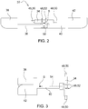
- the Figures 2 and 3 show schematic top views of a first exemplary embodiment according to the invention of a ballasting device 32 in an open position ( Figure 2 ) and in a closed position ( Figure 3 ).
- the ones in the Figures 2 and 3 The ballasting device 32 shown essentially corresponds to that in FIG Figure 1 Ballasting device 32 shown, so that only the differences will be discussed below.
- the open position in Figure 2 it is shown schematically that the center of gravity S has no or a minimal distance from the ballast body 34. If the first and second ballasting arms 36, 40 are in the closed position in Figure 3 adjusted, in particular pivoted relative to one another, the center of gravity S of the ballasting device 32 shifts to a maximum distance 54 from the ballasting body 34.
- first and second bearing axes 44, 46 are arranged spatially coinciding with one another, in particular designed as a common axis of rotation 58, so that the first and second ballasting arms 36, 40 are pivotably mounted or articulated on the ballasting body 34 about the common axis of rotation 58.
- the first and second ballasting arms 36, 40 are arranged sequentially, that is to say one after the other or one above the other, along the common axis of rotation 58.
- the first ballast arm 36 and the first Ballasting weight 38 as well as the second ballasting arm 40 and the second ballasting weight 42 are formed in one piece.
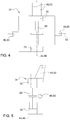
- the Figures 4 and 5 show schematic representations of the ballast body 34 of the first exemplary embodiment according to the invention of the ballast device 32 from FIG Figures 2 and 3 so that only the differences are discussed below.
- the one in the Figures 4 and 5 Ballast body 34 shown is the same ballast body 34.
- a common bearing device is provided for mounting the first and second ballasting arms 36, 40 on the ballasting body 34.
- the common bearing device comprises a common fastening element 58, which is also designed as a common axis of rotation 58, and a common holding element 70, which is designed as part of the ballast body 34.
- the first and / or second or common fastening element 58 can be, for example, a pin and / or a bolt and / or a screw with a nut.
- the common holding element 70 and the ballast body 34 are made in one piece, ie as a common component.
- the first and second ballasting arms 36, 40 each have a through-hole at their respective first end, that is to say the end articulated on the ballasting body 34.
- the first and second ballast arms 36, 40 are therefore articulated to the ballast body 34 by means of the common fastening element 58, the common fastening element 58 being guided through the two holding elements 70 and locked or fastened to the ballast body 34.
- the receiving device 48 with the two receiving bolts 50 and the receiving bearing 52 are designed as a part of the ballast body 34, ie the ballast body 34 and the receiving device 48 are formed in one piece.
- FIG Figure 6 shows a schematic top view of a second exemplary embodiment of the ballasting device 32 according to the invention in an open position and FIG Figure 7 shows a schematic representation of a ballast body 34 of the second exemplary embodiment of the ballast device 32 according to the invention.
- Ballast bodies shown essentially correspond to those in FIG Figures 1 to 5 Ballast devices 32 shown or ballast bodies 34, so that only the differences will be discussed below.
- An essential difference is that the first and second bearing axles 44, 46 are arranged parallel to one another.
- the first and second bearing axes 44, 46 are arranged orthogonally to the pivot axis 56.
- the ballasting device 32 comprises a common bearing device for mounting the first ballast arm and second ballast arm.
- the common bearing device which comprises a first and second fastening element 62, 66 and a common holding element 70
- the first ballast arm 36 at the first end of the first ballast arm 36 is pivotable on the ballast body 34
- the second ballast arm 40 is pivotable at the first end of the second ballast arm 40 mounted and articulated on the ballast body 34.
- the first and second ballasting arms 36, 40 can also be pivoted relative to one another.
- the first and second fastening elements 62, 66 are designed at the same time as first and second bearing axles 44, 46.
- the first and second bearing axes 44, 46 and thus the first and second fastening elements 62, 66 are arranged spatially parallel to one another.
- the common holding element 70 is designed as part of the ballast body 34, ie the two components are designed in one piece as a common component. It cannot be seen that the first and second ballasting arms 36, 40 each have a through-hole at their respective first end, that is to say the end articulated on the ballasting body 34.
- the first and second ballasting arms 36, 40 are therefore articulated to the ballasting body 34 by means of the first and second fastening elements 62, 66, the first and second fastening elements 62, 66 being guided through the through bores and the common holding element 70 and being locked or fastened to the ballasting body 34 are.
- FIG. 11 shows a schematic perspective illustration of a third exemplary embodiment according to the invention of the ballasting device 32 in an open position, which essentially corresponds to that shown in FIGS Figures 1 to 7 corresponds to ballasting devices 32 shown, only the differences will be discussed below.
- the first and second ballast animal weights 38, 42 comprise a plurality of individual weights which are releasably connected to the first and second ballasting arms 36, 40 and / or are fastened or locked to them.
- the individual weights can simply be hooked into the respective ballast arm. As a result, greater flexibility with regard to ballasting can advantageously be achieved.
- FIG. 11 shows a schematic perspective illustration of a fourth exemplary embodiment according to the invention of the ballasting device 32 in an open position, which essentially corresponds to the one shown in FIG Figures 1 to 8 corresponds to ballasting devices 32 shown, only the differences will be discussed below.
- the first ballast arm 36 is on, in particular in, the first holding element 60 and the second ballast arm 40 are arranged on, in particular in, the second holding element 64, in particular releasably connected to the respective holding element.
- the first ballasting arm 36 and the first holding element 60 are connected by means of the first fastening element 62, which is also designed as a first bearing axis 44, and the second ballasting arm 40 and the second holding element 64 are by means of the second fastening element 66, which is also designed as a second bearing axis 46 , pivotable, in particular pivotable relative to one another, mounted and / or articulated on the ballast body 34.
- the ballasting device 32 also comprises a first actuator 68 which is arranged on the first holding element 60, preferably fastened to it or detachably connected to it, in particular rotatably fastened to it or detachably and rotatably connected to it.
- the first actuator 68 is designed as a lifting cylinder with a piston and / or a piston rod.
- the cylinder of the first actuator 68 or lifting cylinder is rotatably attached to the first holding element and its piston rod is rotatably attached to the second holding element 64, whereby the first and second holding elements 60, 64 are operatively connected by means of the actuator.
- the first actuator 68 By actuating the first actuator 68, the first holding element 60 and thus also the first ballast arm 36 can be pivoted.
- a force is also transmitted to the second holding element 64 and thus the second ballasting arm 40 is also pivoted.
- the first and second ballasting arms 36, 40 can therefore be pivoted relative to one another, the movement of the first and second holding elements 60, 64 and thus of the first and second ballasting arms 36, 40 running synchronously.
- the first actuator 68 is arranged on the first and second holding elements 60, 64 in such a way that the ballasting device 32 is in the closed position when the piston and / or piston rod is fully extended from the cylinder and in the open position when the piston and / or piston rod is fully retracted.
- FIG 10 shows a schematic representation of a fifth exemplary embodiment according to the invention of the ballasting device 32 in an open position.
- the ballast device 32 in Figure 10 essentially corresponds to those in the Figures 1 to 9 Ballasting devices 32 shown, only the differences being discussed below.
- Figure 10 shows the first and second holding element 60, 64 which are operatively connected by means of a connecting element 72, here a lever, so that a movement of the first and second holding element 60, 64 and thus of the first and second ballasting arm 36, 40 is synchronous.
- FIG 11 shows a schematic representation of a sixth exemplary embodiment of the ballasting device 32 according to the invention in an open position.
- the ballast device 32 in Figure 11 essentially corresponds to those in the Figures 1 to 10 Ballast devices 32 shown, which is why only the differences will be discussed below.
- Figure 11 shows a first ballasting arm 36, which at the articulated end, comprises a first active element 74, which is designed as a gear, and a second ballasting arm 40, which at the articulated end comprises a second active element 76, which is designed as a gear.
- the first and second active elements 74, 76 are operatively connected in that they mesh with one another.
- the second active element 76 can also be connected to a second actuator 78 in such a way that when the second actuator is actuated, the first and second ballasting arms 36, 40 are pivoted against each other due to the counter-rotating of the first and second active element 74, 76 and due to the Active connection causes a movement of the first and second active element 74, 76 a movement, in particular a pivoting movement, of the first and second ballasting arm 36, 40, the movement running synchronously.
- the first ballast arm 36 and the first active element 74 are in one piece, that is to say formed as one component.
- the second ballasting arm 40 and the second active element 76 are in one piece, that is to say formed as one component.
- FIG 12 shows a schematic top view of a seventh exemplary embodiment of the ballasting device 32 according to the invention in an open position.
- the ballasting device 32 essentially corresponds to that in FIG Figures 1 to 11 Ballast devices 32 shown, so that only the differences will be discussed below.
- the first and second ballasting arms 36, 40 are designed as telescopic ballasting arms that are variable in length.
- the first and second ballasting arms 36, 40 are each designed in two pieces, that is, each comprise two detachable arm elements 80, 82.
- the arm elements 80, 82 are guided into one another, which means that one arm element 80 is arranged and guided in the other arm element 82 so that the Arm elements 80, 82 are adjustable relative to one another.
- a relative movement of the two arm elements 80, 82 to one another is blocked by, for example, inserting a pin or a bolt through bores or holes in the two arm elements so that the arm elements 80, 82 are locked.
- the Figures 13 and 14th show a schematic representation of a ballasting device 32 according to the invention in a state picked up by a three-point coupling device 22 in a position close to the vehicle and a position remote from the vehicle.
- the Ballast device 32 essentially corresponds to that in FIG Figures 1 to 12 Ballast devices 32 shown, so that only the differences will be discussed below.
- Figure 13 shows a ballasting device 32 in the open position in the position close to the vehicle, the center of gravity of the center of gravity S of the ballasting device 32 being arranged below the pivot axis 56 defined by the receiving device 48.
- FIG 14 shows a ballasting device 32 in the open position in the position remote from the vehicle, the center of gravity of the center of gravity S of the ballasting device being arranged above the pivot axis 56 defined by the receiving device 48.
- the ballasting device 32 can be adjusted and / or adjusted from the position close to the vehicle to the position remote from the vehicle and in all positions in between by lowering or raising the lower links 28 in conjunction with a rigid or length-adjustable upper link 26.
- the center of gravity S of the ballast weight 32 assumes a higher center of gravity position in the position close to the vehicle than in the position remote from the vehicle.
- the setting of the center of gravity S of the ballasting device 32 can advantageously be combined with the setting of the position of the center of gravity of the ballasting device 32 in a received state of the ballasting device 32 with respect to the vehicle.
Landscapes
- Engineering & Computer Science (AREA)
- Chemical & Material Sciences (AREA)
- Combustion & Propulsion (AREA)
- Transportation (AREA)
- Mechanical Engineering (AREA)
- Agricultural Machines (AREA)
Claims (12)
- Dispositif de ballastage pour un véhicule agricole (10, 12), comprenant
un corps de ballastage (34) et un premier bras de ballastage (36) et un deuxième bras de ballastage (40),
le premier bras de ballastage (36) étant monté pivotant par une extrémité autour d'un premier axe de palier (44) sur le corps de ballastage (34), et à l'autre extrémité duquel est disposé un premier poids de ballastage (38),
et le deuxième bras de ballastage (40) est monté pivotant par une extrémité autour d'un deuxième axe de palier (46) sur le corps de ballastage (34), et à l'autre extrémité duquel est disposé un deuxième poids de ballastage (42),
le dispositif de ballastage (32) présentant un dispositif de réception (48, 50, 52) pour recevoir le dispositif de ballastage (32) au moyen d'un dispositif d'attelage trois points (22) du véhicule agricole (10, 12),
et le premier poids de ballastage (38) étant réglable au moyen du premier bras de ballastage (36), et le deuxième poids de ballastage (42) étant réglable au moyen du deuxième bras de ballastage (40). - Dispositif de ballastage selon la revendication 1, caractérisé en ce que le premier et le deuxième axe de palier (44, 46) sont disposés l'un par rapport à l'autre en parallèle ou en coïncidant dans l'espace.
- Dispositif de ballastage selon la revendication 1 ou 2, caractérisé en ce que le dispositif de ballastage (32) comprend un premier ensemble de palier pour supporter le premier bras de ballastage (36) sur le corps de ballastage (34) et/ou un deuxième ensemble de palier pour supporter le deuxième bras de ballastage (40) sur le corps de ballastage (34).
- Dispositif de ballastage selon la revendication 3, caractérisé en ce que le premier ensemble de palier comprend un premier élément de fixation (62) et/ou un premier élément de maintien (60), et/ou le deuxième ensemble de palier comprend un deuxième élément de fixation (66) et/ou un deuxième élément de maintien (64).
- Dispositif de ballastage selon l'une quelconque des revendications précédentes, caractérisé en ce que le premier et/ou le deuxième bras de ballastage (36, 40) et/ou le premier et/ou le deuxième élément de maintien (60, 64) sont en relation active les uns avec les autres.
- Dispositif de ballastage selon l'une quelconque des revendications précédentes, caractérisé en ce que le premier bras de ballastage (36) présente à une extrémité un premier élément actif (74), et le deuxième bras de ballastage (40) présente à une extrémité un deuxième élément actif (76), le premier et le deuxième élément actif (74, 76) étant en relation active l'un avec l'autre.
- Dispositif de ballastage selon l'une quelconque des revendications précédentes, caractérisé en ce que le dispositif de ballastage (32) comprend un premier actionneur (68) permettant de régler le premier bras de ballastage (36) autour du premier axe de palier (44), et/ou le dispositif de ballastage (32) comprend un deuxième actionneur (78) permettant de régler le deuxième bras de ballastage (40) autour du deuxième axe de palier (46) .
- Dispositif de ballastage selon l'une quelconque des revendications précédentes, caractérisé en ce que le dispositif de ballastage (32) comprend un ou plusieurs tampons de butée et/ou un ou plusieurs équipements d'arrêt.
- Dispositif de ballastage selon l'une quelconque des revendications précédentes, caractérisé en ce que le premier et/ou le deuxième bras de ballastage (36, 40) sont réalisés sous forme de bras de ballastage télescopiques (36, 40).
- Dispositif de ballastage selon l'une quelconque des revendications précédentes, caractérisé en ce que le premier poids de ballastage (38) et/ou le deuxième poids de ballastage (42) comprennent un ou plusieurs poids individuels.
- Véhicule agricole comprenant un dispositif de ballastage (32) selon l'une quelconque des revendications 1 à 10.
- Véhicule agricole selon la revendication 11, caractérisé en ce que le véhicule agricole (10, 12) comprend un dispositif d'attelage trois points (22), le dispositif de ballastage (32) pouvant être reçu, en particulier étant reçu, par le dispositif d'attelage trois points (22).
Applications Claiming Priority (1)
| Application Number | Priority Date | Filing Date | Title |
|---|---|---|---|
| DE102018217286.2A DE102018217286A1 (de) | 2018-10-10 | 2018-10-10 | Ballastiervorrichtung und landwirtschaftliches Fahrzeug |
Publications (2)
| Publication Number | Publication Date |
|---|---|
| EP3636520A1 EP3636520A1 (fr) | 2020-04-15 |
| EP3636520B1 true EP3636520B1 (fr) | 2021-07-21 |
Family
ID=67956567
Family Applications (1)
| Application Number | Title | Priority Date | Filing Date |
|---|---|---|---|
| EP19197281.9A Active EP3636520B1 (fr) | 2018-10-10 | 2019-09-13 | Dispositif de ballastage et véhicule agricole |
Country Status (3)
| Country | Link |
|---|---|
| US (1) | US11186326B2 (fr) |
| EP (1) | EP3636520B1 (fr) |
| DE (1) | DE102018217286A1 (fr) |
Families Citing this family (3)
| Publication number | Priority date | Publication date | Assignee | Title |
|---|---|---|---|---|
| CA3208142A1 (fr) * | 2021-01-11 | 2022-07-14 | Agtonomy | Drone terrestre multifonctionnel |
| FR3141672B1 (fr) | 2022-11-08 | 2025-04-18 | Pateer France | Élement de lestage comportant un corps creux rotomoulé rempli au moins en partie de béton solidifié en place |
| PL447915A1 (pl) * | 2024-03-01 | 2025-09-08 | Politechnika Poznańska | Obciążnik ciągników rolniczych, maszyn roboczych i samojezdnych zaczepiany na trzypunktowym układzie zawieszenia z regulowanym środkiem ciężkości |
Family Cites Families (16)
| Publication number | Priority date | Publication date | Assignee | Title |
|---|---|---|---|---|
| US2693250A (en) | 1951-08-25 | 1954-11-02 | Barrett Cravens Co | Fork truck having adjustable counterweight |
| US2891681A (en) * | 1956-12-05 | 1959-06-23 | Caterpillar Tractor Co | Rotatable counterweight mechanism |
| DE3442557C2 (de) * | 1984-11-22 | 1986-12-11 | Deere & Co., Moline, Ill., US, Niederlassung Deere & Co. European Office, 6800 Mannheim | Anschluß- und Kupplungsvorrichtung zum frontseitigen Anbau an ein Arbeitsfahrzeug |
| IT212711Z2 (it) * | 1987-11-02 | 1989-08-28 | Same Spa | Metallica per trattori dispositivo di zavorramento a massa |
| JPH0739676B2 (ja) * | 1989-03-15 | 1995-05-01 | 東洋運搬機株式会社 | バランス装置を備えた車両 |
| US6227304B1 (en) * | 1999-03-01 | 2001-05-08 | Case Corporation | Upper hitch link |
| FR2815319A1 (fr) * | 2000-10-13 | 2002-04-19 | Hubert Defrancq | Dispositif pour ameliorer la maitrise de la conduite d'un tracteur a chenilles, et tracteur a chenilles muni de ce dispositif |
| DE102005040954A1 (de) * | 2005-05-31 | 2006-12-07 | Hans Wittrock Gmbh | Vorrichtung zur Balastierung von landwirtschaftlichen Fahrzeugen |
| FR2896658B1 (fr) * | 2006-01-27 | 2010-02-26 | Hubert Defrancq | Dispositif pour faciliter la gestion du lestage d'un tracteur agricole et pour en ameliorer la productivite |
| DE102008043698A1 (de) | 2008-11-13 | 2010-05-20 | Deere & Company, Moline | Ballastiervorrichtung und landwirtschaftliches Fahrzeug mit einer solchen |
| WO2010071380A2 (fr) * | 2008-12-19 | 2010-06-24 | 두산인프라코어 주식회사 | Structure de contrepoids à faible entretien pour équipement lourd |
| US8662460B2 (en) * | 2010-12-03 | 2014-03-04 | Deere & Company | Weight adapter bracket |
| ITUB20155602A1 (it) * | 2015-11-16 | 2017-05-16 | Sandro Dini | Zavorra per macchina operatrice. |
| US10066365B2 (en) * | 2016-01-22 | 2018-09-04 | Hpm—Hydraulic Performance Machines Srl | Public works vehicle provided with counterweight lifting system |
| DE102016009013B4 (de) | 2016-07-25 | 2020-12-10 | Liebherr-Werk Ehingen Gmbh | Ballastiervorrichtung sowie Kranoberwagen |
| DE102018123245A1 (de) * | 2018-09-21 | 2020-03-26 | Claas Tractor Sas | Anbaugewicht für ein landwirtschaftliches Fahrzeug |
-
2018
- 2018-10-10 DE DE102018217286.2A patent/DE102018217286A1/de not_active Withdrawn
-
2019
- 2019-09-13 EP EP19197281.9A patent/EP3636520B1/fr active Active
- 2019-10-04 US US16/593,524 patent/US11186326B2/en active Active
Also Published As
| Publication number | Publication date |
|---|---|
| DE102018217286A1 (de) | 2020-04-16 |
| US20200114989A1 (en) | 2020-04-16 |
| EP3636520A1 (fr) | 2020-04-15 |
| US11186326B2 (en) | 2021-11-30 |
Similar Documents
| Publication | Publication Date | Title |
|---|---|---|
| EP2186713B1 (fr) | Dispositif de ballastage et véhicule agricole équipé avec ce dernier | |
| DE3442557C2 (de) | Anschluß- und Kupplungsvorrichtung zum frontseitigen Anbau an ein Arbeitsfahrzeug | |
| EP0182091B1 (fr) | Elévateur de puissance pour un dispositif de levage | |
| EP2914081B1 (fr) | Charrue demi-tour avec limitation de rotation | |
| DE102019130526B4 (de) | Unterwagensystem für ein Raupenfahrzeug, Raupenfahrzeug und Verfahren zum Teilzerlegen eines Unterwagensystems für einen Transport | |
| EP1008284A2 (fr) | Accouplement télescopique d'outil pour véhicule motorisé | |
| EP3636520A1 (fr) | Dispositif de ballastage et véhicule agricole | |
| EP2708386B1 (fr) | Dispositif d'embrayage pour un véhicule automobile | |
| EP2042410B1 (fr) | Véhicule agricole | |
| DE3322551C2 (de) | Zwischenstück zum Ausschalten der Seitenbeweglichkeit von Unterlenkern eines Ackerschleppers | |
| DE19534695C2 (de) | An einem Schlepper ansetzbares Heckmähwerk | |
| EP2829662B1 (fr) | Système de chargeur frontal | |
| EP1710100B1 (fr) | Accouplement pour charges lourdes | |
| DE202008015659U1 (de) | Kranspitze für einen Ladekran | |
| DE19820377C1 (de) | Arbeitsfahrzeug mit kippbarer Fahrerplattform und Kippvorrichtung | |
| DE3139936A1 (de) | Landwirtschaftliches anhaengegeraet | |
| DE202014103208U1 (de) | An Baumaschine angeordneter Ausleger für Anbaugeräte | |
| EP4101276B1 (fr) | Appareil accessoire destiné au traitement du sol | |
| DE102019123035B4 (de) | Vorrichtung zur Ballastierung von Fahrzeugen, Fahrzeug mit einem Hubwerk, Verfahren zur Anpassung der Ballastierung eines Fahrzeugs | |
| DE9414597U1 (de) | Gezogene Mähmaschine | |
| EP3756436B1 (fr) | Relevage avant ainsi que machine de travail doté d'un relevage avant | |
| DE3722687A1 (de) | Pflug | |
| DE1079374B (de) | Geraeteanbauvorrichtung fuer landwirtschaftliche Zugmaschinen | |
| EP0533081A1 (fr) | Dispositif d'accrochage pour tracteurs | |
| DE10213993C1 (de) | Bodenbearbeitungsgerät mit Stabilisierungseinrichtung |
Legal Events
| Date | Code | Title | Description |
|---|---|---|---|
| PUAI | Public reference made under article 153(3) epc to a published international application that has entered the european phase |
Free format text: ORIGINAL CODE: 0009012 |
|
| STAA | Information on the status of an ep patent application or granted ep patent |
Free format text: STATUS: THE APPLICATION HAS BEEN PUBLISHED |
|
| AK | Designated contracting states |
Kind code of ref document: A1 Designated state(s): AL AT BE BG CH CY CZ DE DK EE ES FI FR GB GR HR HU IE IS IT LI LT LU LV MC MK MT NL NO PL PT RO RS SE SI SK SM TR |
|
| AX | Request for extension of the european patent |
Extension state: BA ME |
|
| STAA | Information on the status of an ep patent application or granted ep patent |
Free format text: STATUS: REQUEST FOR EXAMINATION WAS MADE |
|
| 17P | Request for examination filed |
Effective date: 20201015 |
|
| RBV | Designated contracting states (corrected) |
Designated state(s): AL AT BE BG CH CY CZ DE DK EE ES FI FR GB GR HR HU IE IS IT LI LT LU LV MC MK MT NL NO PL PT RO RS SE SI SK SM TR |
|
| GRAP | Despatch of communication of intention to grant a patent |
Free format text: ORIGINAL CODE: EPIDOSNIGR1 |
|
| STAA | Information on the status of an ep patent application or granted ep patent |
Free format text: STATUS: GRANT OF PATENT IS INTENDED |
|
| RIC1 | Information provided on ipc code assigned before grant |
Ipc: B62D 49/06 20060101AFI20210212BHEP Ipc: B62D 37/04 20060101ALI20210212BHEP |
|
| INTG | Intention to grant announced |
Effective date: 20210301 |
|
| GRAS | Grant fee paid |
Free format text: ORIGINAL CODE: EPIDOSNIGR3 |
|
| GRAA | (expected) grant |
Free format text: ORIGINAL CODE: 0009210 |
|
| STAA | Information on the status of an ep patent application or granted ep patent |
Free format text: STATUS: THE PATENT HAS BEEN GRANTED |
|
| AK | Designated contracting states |
Kind code of ref document: B1 Designated state(s): AL AT BE BG CH CY CZ DE DK EE ES FI FR GB GR HR HU IE IS IT LI LT LU LV MC MK MT NL NO PL PT RO RS SE SI SK SM TR |
|
| REG | Reference to a national code |
Ref country code: GB Ref legal event code: FG4D Free format text: NOT ENGLISH |
|
| REG | Reference to a national code |
Ref country code: CH Ref legal event code: EP |
|
| REG | Reference to a national code |
Ref country code: DE Ref legal event code: R096 Ref document number: 502019001857 Country of ref document: DE |
|
| REG | Reference to a national code |
Ref country code: AT Ref legal event code: REF Ref document number: 1412373 Country of ref document: AT Kind code of ref document: T Effective date: 20210815 |
|
| REG | Reference to a national code |
Ref country code: IE Ref legal event code: FG4D Free format text: LANGUAGE OF EP DOCUMENT: GERMAN |
|
| REG | Reference to a national code |
Ref country code: LT Ref legal event code: MG9D |
|
| REG | Reference to a national code |
Ref country code: NL Ref legal event code: FP |
|
| PG25 | Lapsed in a contracting state [announced via postgrant information from national office to epo] |
Ref country code: SE Free format text: LAPSE BECAUSE OF FAILURE TO SUBMIT A TRANSLATION OF THE DESCRIPTION OR TO PAY THE FEE WITHIN THE PRESCRIBED TIME-LIMIT Effective date: 20210721 Ref country code: RS Free format text: LAPSE BECAUSE OF FAILURE TO SUBMIT A TRANSLATION OF THE DESCRIPTION OR TO PAY THE FEE WITHIN THE PRESCRIBED TIME-LIMIT Effective date: 20210721 Ref country code: ES Free format text: LAPSE BECAUSE OF FAILURE TO SUBMIT A TRANSLATION OF THE DESCRIPTION OR TO PAY THE FEE WITHIN THE PRESCRIBED TIME-LIMIT Effective date: 20210721 Ref country code: FI Free format text: LAPSE BECAUSE OF FAILURE TO SUBMIT A TRANSLATION OF THE DESCRIPTION OR TO PAY THE FEE WITHIN THE PRESCRIBED TIME-LIMIT Effective date: 20210721 Ref country code: LT Free format text: LAPSE BECAUSE OF FAILURE TO SUBMIT A TRANSLATION OF THE DESCRIPTION OR TO PAY THE FEE WITHIN THE PRESCRIBED TIME-LIMIT Effective date: 20210721 Ref country code: BG Free format text: LAPSE BECAUSE OF FAILURE TO SUBMIT A TRANSLATION OF THE DESCRIPTION OR TO PAY THE FEE WITHIN THE PRESCRIBED TIME-LIMIT Effective date: 20211021 Ref country code: HR Free format text: LAPSE BECAUSE OF FAILURE TO SUBMIT A TRANSLATION OF THE DESCRIPTION OR TO PAY THE FEE WITHIN THE PRESCRIBED TIME-LIMIT Effective date: 20210721 Ref country code: PT Free format text: LAPSE BECAUSE OF FAILURE TO SUBMIT A TRANSLATION OF THE DESCRIPTION OR TO PAY THE FEE WITHIN THE PRESCRIBED TIME-LIMIT Effective date: 20211122 Ref country code: NO Free format text: LAPSE BECAUSE OF FAILURE TO SUBMIT A TRANSLATION OF THE DESCRIPTION OR TO PAY THE FEE WITHIN THE PRESCRIBED TIME-LIMIT Effective date: 20211021 |
|
| PG25 | Lapsed in a contracting state [announced via postgrant information from national office to epo] |
Ref country code: PL Free format text: LAPSE BECAUSE OF FAILURE TO SUBMIT A TRANSLATION OF THE DESCRIPTION OR TO PAY THE FEE WITHIN THE PRESCRIBED TIME-LIMIT Effective date: 20210721 Ref country code: LV Free format text: LAPSE BECAUSE OF FAILURE TO SUBMIT A TRANSLATION OF THE DESCRIPTION OR TO PAY THE FEE WITHIN THE PRESCRIBED TIME-LIMIT Effective date: 20210721 Ref country code: GR Free format text: LAPSE BECAUSE OF FAILURE TO SUBMIT A TRANSLATION OF THE DESCRIPTION OR TO PAY THE FEE WITHIN THE PRESCRIBED TIME-LIMIT Effective date: 20211022 |
|
| REG | Reference to a national code |
Ref country code: DE Ref legal event code: R097 Ref document number: 502019001857 Country of ref document: DE |
|
| PG25 | Lapsed in a contracting state [announced via postgrant information from national office to epo] |
Ref country code: DK Free format text: LAPSE BECAUSE OF FAILURE TO SUBMIT A TRANSLATION OF THE DESCRIPTION OR TO PAY THE FEE WITHIN THE PRESCRIBED TIME-LIMIT Effective date: 20210721 |
|
| REG | Reference to a national code |
Ref country code: BE Ref legal event code: MM Effective date: 20210930 |
|
| PLBE | No opposition filed within time limit |
Free format text: ORIGINAL CODE: 0009261 |
|
| STAA | Information on the status of an ep patent application or granted ep patent |
Free format text: STATUS: NO OPPOSITION FILED WITHIN TIME LIMIT |
|
| PG25 | Lapsed in a contracting state [announced via postgrant information from national office to epo] |
Ref country code: SM Free format text: LAPSE BECAUSE OF FAILURE TO SUBMIT A TRANSLATION OF THE DESCRIPTION OR TO PAY THE FEE WITHIN THE PRESCRIBED TIME-LIMIT Effective date: 20210721 Ref country code: SK Free format text: LAPSE BECAUSE OF FAILURE TO SUBMIT A TRANSLATION OF THE DESCRIPTION OR TO PAY THE FEE WITHIN THE PRESCRIBED TIME-LIMIT Effective date: 20210721 Ref country code: RO Free format text: LAPSE BECAUSE OF FAILURE TO SUBMIT A TRANSLATION OF THE DESCRIPTION OR TO PAY THE FEE WITHIN THE PRESCRIBED TIME-LIMIT Effective date: 20210721 Ref country code: MC Free format text: LAPSE BECAUSE OF FAILURE TO SUBMIT A TRANSLATION OF THE DESCRIPTION OR TO PAY THE FEE WITHIN THE PRESCRIBED TIME-LIMIT Effective date: 20210721 Ref country code: EE Free format text: LAPSE BECAUSE OF FAILURE TO SUBMIT A TRANSLATION OF THE DESCRIPTION OR TO PAY THE FEE WITHIN THE PRESCRIBED TIME-LIMIT Effective date: 20210721 Ref country code: CZ Free format text: LAPSE BECAUSE OF FAILURE TO SUBMIT A TRANSLATION OF THE DESCRIPTION OR TO PAY THE FEE WITHIN THE PRESCRIBED TIME-LIMIT Effective date: 20210721 Ref country code: AL Free format text: LAPSE BECAUSE OF FAILURE TO SUBMIT A TRANSLATION OF THE DESCRIPTION OR TO PAY THE FEE WITHIN THE PRESCRIBED TIME-LIMIT Effective date: 20210721 |
|
| 26N | No opposition filed |
Effective date: 20220422 |
|
| PG25 | Lapsed in a contracting state [announced via postgrant information from national office to epo] |
Ref country code: LU Free format text: LAPSE BECAUSE OF NON-PAYMENT OF DUE FEES Effective date: 20210913 Ref country code: IT Free format text: LAPSE BECAUSE OF FAILURE TO SUBMIT A TRANSLATION OF THE DESCRIPTION OR TO PAY THE FEE WITHIN THE PRESCRIBED TIME-LIMIT Effective date: 20210721 Ref country code: IE Free format text: LAPSE BECAUSE OF NON-PAYMENT OF DUE FEES Effective date: 20210913 Ref country code: BE Free format text: LAPSE BECAUSE OF NON-PAYMENT OF DUE FEES Effective date: 20210930 |
|
| REG | Reference to a national code |
Ref country code: CH Ref legal event code: PL |
|
| PG25 | Lapsed in a contracting state [announced via postgrant information from national office to epo] |
Ref country code: CY Free format text: LAPSE BECAUSE OF FAILURE TO SUBMIT A TRANSLATION OF THE DESCRIPTION OR TO PAY THE FEE WITHIN THE PRESCRIBED TIME-LIMIT Effective date: 20210721 |
|
| PG25 | Lapsed in a contracting state [announced via postgrant information from national office to epo] |
Ref country code: LI Free format text: LAPSE BECAUSE OF NON-PAYMENT OF DUE FEES Effective date: 20220930 Ref country code: HU Free format text: LAPSE BECAUSE OF FAILURE TO SUBMIT A TRANSLATION OF THE DESCRIPTION OR TO PAY THE FEE WITHIN THE PRESCRIBED TIME-LIMIT; INVALID AB INITIO Effective date: 20190913 Ref country code: CH Free format text: LAPSE BECAUSE OF NON-PAYMENT OF DUE FEES Effective date: 20220930 |
|
| PG25 | Lapsed in a contracting state [announced via postgrant information from national office to epo] |
Ref country code: MK Free format text: LAPSE BECAUSE OF FAILURE TO SUBMIT A TRANSLATION OF THE DESCRIPTION OR TO PAY THE FEE WITHIN THE PRESCRIBED TIME-LIMIT Effective date: 20210721 |
|
| PG25 | Lapsed in a contracting state [announced via postgrant information from national office to epo] |
Ref country code: MT Free format text: LAPSE BECAUSE OF FAILURE TO SUBMIT A TRANSLATION OF THE DESCRIPTION OR TO PAY THE FEE WITHIN THE PRESCRIBED TIME-LIMIT Effective date: 20210721 |
|
| PGFP | Annual fee paid to national office [announced via postgrant information from national office to epo] |
Ref country code: DE Payment date: 20250820 Year of fee payment: 7 |
|
| PGFP | Annual fee paid to national office [announced via postgrant information from national office to epo] |
Ref country code: NL Payment date: 20250926 Year of fee payment: 7 |
|
| PGFP | Annual fee paid to national office [announced via postgrant information from national office to epo] |
Ref country code: GB Payment date: 20250929 Year of fee payment: 7 |
|
| PGFP | Annual fee paid to national office [announced via postgrant information from national office to epo] |
Ref country code: FR Payment date: 20250925 Year of fee payment: 7 |
|
| REG | Reference to a national code |
Ref country code: AT Ref legal event code: MM01 Ref document number: 1412373 Country of ref document: AT Kind code of ref document: T Effective date: 20240913 |
|
| PG25 | Lapsed in a contracting state [announced via postgrant information from national office to epo] |
Ref country code: TR Free format text: LAPSE BECAUSE OF FAILURE TO SUBMIT A TRANSLATION OF THE DESCRIPTION OR TO PAY THE FEE WITHIN THE PRESCRIBED TIME-LIMIT Effective date: 20210721 |
|
| PG25 | Lapsed in a contracting state [announced via postgrant information from national office to epo] |
Ref country code: AT Free format text: LAPSE BECAUSE OF NON-PAYMENT OF DUE FEES Effective date: 20240913 |
|
| PGFP | Annual fee paid to national office [announced via postgrant information from national office to epo] |
Ref country code: AT Payment date: 20260410 Year of fee payment: 5 |