EP3636841A1 - Dispositif de montage pour un élément encastré - Google Patents
Dispositif de montage pour un élément encastré Download PDFInfo
- Publication number
- EP3636841A1 EP3636841A1 EP19190133.9A EP19190133A EP3636841A1 EP 3636841 A1 EP3636841 A1 EP 3636841A1 EP 19190133 A EP19190133 A EP 19190133A EP 3636841 A1 EP3636841 A1 EP 3636841A1
- Authority
- EP
- European Patent Office
- Prior art keywords
- fixing
- installation
- mounting device
- receiving device
- mounting
- Prior art date
- Legal status (The legal status is an assumption and is not a legal conclusion. Google has not performed a legal analysis and makes no representation as to the accuracy of the status listed.)
- Pending
Links
- 238000009434 installation Methods 0.000 title claims abstract description 109
- 238000003780 insertion Methods 0.000 claims abstract description 4
- 230000037431 insertion Effects 0.000 claims abstract description 4
- 229920001296 polysiloxane Polymers 0.000 claims description 12
- 238000000034 method Methods 0.000 claims description 11
- 125000006850 spacer group Chemical group 0.000 claims description 10
- 239000002390 adhesive tape Substances 0.000 claims description 9
- 239000000853 adhesive Substances 0.000 claims description 6
- 230000001070 adhesive effect Effects 0.000 claims description 6
- 239000000565 sealant Substances 0.000 claims description 5
- 210000002414 leg Anatomy 0.000 description 20
- 238000004519 manufacturing process Methods 0.000 description 6
- 239000000463 material Substances 0.000 description 2
- XLYOFNOQVPJJNP-UHFFFAOYSA-N water Substances O XLYOFNOQVPJJNP-UHFFFAOYSA-N 0.000 description 2
- 229910000831 Steel Inorganic materials 0.000 description 1
- 238000004026 adhesive bonding Methods 0.000 description 1
- 238000004140 cleaning Methods 0.000 description 1
- 230000001427 coherent effect Effects 0.000 description 1
- 238000002347 injection Methods 0.000 description 1
- 239000007924 injection Substances 0.000 description 1
- 239000007788 liquid Substances 0.000 description 1
- 239000002184 metal Substances 0.000 description 1
- 230000002093 peripheral effect Effects 0.000 description 1
- 230000001681 protective effect Effects 0.000 description 1
- 238000010079 rubber tapping Methods 0.000 description 1
- 238000000926 separation method Methods 0.000 description 1
- 229910001220 stainless steel Inorganic materials 0.000 description 1
- 239000010935 stainless steel Substances 0.000 description 1
- 239000010959 steel Substances 0.000 description 1
- 238000003860 storage Methods 0.000 description 1
- 210000000689 upper leg Anatomy 0.000 description 1
- 230000000007 visual effect Effects 0.000 description 1
Images


Classifications
-
- E—FIXED CONSTRUCTIONS
- E03—WATER SUPPLY; SEWERAGE
- E03C—DOMESTIC PLUMBING INSTALLATIONS FOR FRESH WATER OR WASTE WATER; SINKS
- E03C1/00—Domestic plumbing installations for fresh water or waste water; Sinks
- E03C1/12—Plumbing installations for waste water; Basins or fountains connected thereto; Sinks
- E03C1/32—Holders or supports for basins
- E03C1/33—Fastening sinks or basins in an apertured support
- E03C1/335—Fastening sinks or basins in an apertured support the fastening means comprising a screw
-
- E—FIXED CONSTRUCTIONS
- E03—WATER SUPPLY; SEWERAGE
- E03C—DOMESTIC PLUMBING INSTALLATIONS FOR FRESH WATER OR WASTE WATER; SINKS
- E03C1/00—Domestic plumbing installations for fresh water or waste water; Sinks
- E03C1/12—Plumbing installations for waste water; Basins or fountains connected thereto; Sinks
- E03C1/32—Holders or supports for basins
- E03C1/33—Fastening sinks or basins in an apertured support
Definitions
- the invention relates to a mounting device for a built-in element, in particular a sanitary built-in element such as a sink, a sink or the like, for insertion in a receiving device.
- the invention further relates to a method for installing a built-in element in a receiving device by means of a mounting device.
- the present invention is generally applicable to any receptacle, the present invention will be described in relation to kitchen worktop receptacles.
- Countertops for kitchens serve as storage space or as a work surface for preparing or preparing food.
- Worktops usually have cutouts to accommodate a sink or the like, for example.
- the edge of the sink or sink can protrude beyond the worktop, so that the worktop supports the sink by means of a peripheral edge.
- the sink can protrude or protrude vertically from the worktop. It is also conceivable to install the sink in such a way that it is flush with the worktop, in other words that a common plane is formed between the top edge of the worktop and the top edge of the sink, so that easy cleaning and a high visual appearance are achieved.
- silicone is usually introduced into this intermediate area, which solidifies after a certain time and prevents water from entering.
- This intermediate area is essentially formed by an area not visible from above and an area visible from above.
- the problem with flush-mounted installation in particular is that the sink must be aligned exactly within the corresponding opening in the worktop, and at the same time a well-dosed amount of silicone must be introduced into the intermediate area.
- a sink has become known, which is pressed by means of a mounting frame from below into a recess in a worktop.
- the mounting frame has four spacers acting in the vertical direction, which are supported on corresponding projections of the base of the worktop.
- a securing device for fixing a basin in a recess of a plate or the like is shown.
- the safety device is fixed on the basin below the plate.
- a movable element of the securing device can be moved upwards after the basin has been introduced into the recess, so that the worktop can be clamped between the upper edge of the basin and the securing device on the underside.
- the assembly device should be able to be used flexibly for a large number of different installation elements.
- Another object of the present invention is to provide an alternative mounting device and an alternative method for installing a built-in element in a receiving device.
- the present invention achieves the above-mentioned objects with an embodiment in the form of a mounting device for a built-in element, in particular a sanitary built-in element such as a sink, a wash basin or the like, for insertion into a receiving device along an installation direction, in that the mounting device on the one hand with the built-in element, on the other hand cooperates with the receiving device in such a way that the relative position, at least along the installation direction of the installation element and the receiving device, can be adjusted with respect to one another by means of an adjusting device, and wherein the adjusting device interacts with fixing areas of the installation element and receiving device which have different spatial orientations.
- One of the advantages achieved is that the exact positioning of the built-in element and receiving device can be flexibly adjusted relative to one another, so that, for example, silicone can be easily inserted into a set gap and then the upper edges of the built-in element and worktop can be set or flushed in a simple and reliable manner can be arranged.
- Another advantage is that the assembly device can be used flexibly for a large number of different configurations of installation elements and receiving devices, which reduces the manufacturing costs reduced for the mounting device.
- Another advantage is the ease of handling, since there is no need for extensive instruction in the operation or handling of the assembly device.
- the mounting device comprises two fixing elements, one being connectable, in particular detachable, to the fixing area of the mounting element and one to the fixing area of the receiving device.
- the mounting device can be connected in a simple manner to the installation element and receiving device for setting the relative position. If the mounting device is detachably connected to the installation element or receiving device, it can be removed again after the installation of the installation element has been completed, so that costs are saved on the one hand if the installation device can then also be used for other installation elements for its installation and Mounting device required space, for example, increased below the worktop again.
- At least one of the fixing elements has a fixing surface, the surface normal of which is oriented perpendicular to the direction of installation.
- the mounting device can thus be fixed in a flexible manner even in the case of limited space on the installation element or receiving devices.
- fixing surfaces of the fixing elements have the same geometric shape, in particular they are rectangular. This enables simple and inexpensive manufacture of the assembly device.
- At least one of the fixing elements has an adhesive element and / or a vacuum device and / or a screwing device for fixing the fixing element to the mounting element and / or to the receiving device.
- the advantage of this is that in the case of an adhesive element, the mounting device can be fixed simply and quickly on the installation element or receiving device is possible.
- the fixing element has a vacuum device and / or a screw device, it is particularly easy to detach the mounting device and the mounting element or mounting device after the mounting element has been installed.
- the screw device can, for example, include corresponding drill holes for screws that can be inserted into them. It is also conceivable to arrange screws captively in the drill holes so that they do not have to be inserted into them first.
- appropriately designed fixing areas for cooperation with the vacuum device can already be present on the installation element and / or on the receiving device or can be arranged during assembly.
- At least one of the fixing elements is L-shaped, in particular with the shorter section of the L-shaped fixing element being oriented essentially perpendicular to the direction of installation.
- the adjusting device has an adjusting element, in particular comprising an adjusting screw, which interacts with one of the fixing elements for adjusting the relative position, in particular wherein the fixing element has a thread corresponding to the adjusting screw.
- the setting device interacts with the shorter section of the L-shaped fixing element. This minimizes the installation space perpendicular to the direction of installation.
- the mounting device has a clamping device for providing an operating position for an adjusting element of the adjusting device.
- a simple assembly of a Adjustment element take place in that this is jammed in an operating position.
- the adjusting element can be inserted into a first recess in one of the fixing elements and, via the first recess, into a second recess to provide the operating position in the second recess.
- the setting element comprises an actuating element in the form of a rotary knob and / or is designed with a driving profile which has a tapered section, in particular in the middle of its extent.
- the tapered section of the actuating element is designed to correspond to the second recess on the one hand and to a connection between the first and second recess to provide the operating position on the other hand.
- An operating position or captivity of the actuating element can thus be provided in a simple and reliable manner.
- the mounting device has in particular at least one of the fixing elements, at least one spacer element for spacing the mounting device from the installation element and / or receiving device.
- At least one of the fixing elements is formed at least in two parts with a first part and a second part.
- the first and second parts can be releasably fixed to one another by means of a positive connection.
- the advantage is a simple fixing of the two parts to one another to form the fixing element.
- the thickness of the at least two parts is different. In this way, increased stability against tilting of the two parts against each other can be provided in a simple and inexpensive manner.
- one of the two parts of the at least one fixing element is L-shaped. This allows the fixing element formed by the two parts to be oriented in two different directions in a simple manner.
- the positive connection is designed as at least one dovetail connection. This enables a stable and at the same time inexpensive provision of a connection between the two parts.
- the first and second parts can be fixed to one another perpendicular to the direction of installation. A particularly simple fixing of the two parts to one another is thus possible.
- the ratio of the extent of the first and second part parallel to the direction of installation is at least 1: 3, in particular at least 1: 5.
- one of the fixing elements is formed at least in two parts with a first part and a second part, which can be detachably fixed to one another.
- the first part and the second part can be arranged essentially perpendicular to one another and at least one of the parts has at least one horizontal offset and at least one horizontal slot for releasably arranging the at least one other part.
- the two parts can thus be fixed to one another in a particularly simple manner.
- the first part has a plurality of horizontal slots. This means that the second part can be arranged at different heights, for example when the first part is oriented vertically, so that the flexibility during installation is increased.
- the second part is designed in cross section as a T-shaped profile, in particular wherein the head of the T-shaped profile of the second part can be arranged between the installation element and the first part.
- the horizontal offset is designed such that it corresponds to the horizontal thickness of the head of the T-shaped profile of the second part.
- the mounting device is removed after the mounting element and receiving device have been installed.
- this enables a particularly cost-effective production of the assembly device, at the same time increasing the flexibility, since the assembly device can then be used for further installation elements.
- the installation space is also optimized, since the assembly device only has to remain on the installation element or receiving device during assembly, but not constantly.
- the assembly device fixed on the installation element and / or on the receiving device by means of a double-sided adhesive tape and / or by means of a screw connection.
- Figure 1 shows a mounting device according to an embodiment of the present invention schematically and in cross section.
- the assembly device 1 comprises a first L-shaped fixing element 5a and a second fixing element 5b, which is T-shaped here.
- the first fixing element 5a is fixed with the longer leg 8a ', which has a fixing surface 6a, to a partial area of the vertical edge 2a of the built-in element 2 by means of double-sided adhesive tape 7a.
- the longer or larger leg 8a 'of the fixing element 5a is also oriented in the vertical direction.
- the second fixing element 5b comprises a substantially horizontal area as a fixing surface 6b, on which a double-sided adhesive tape 7b is arranged, for fixing with a horizontally oriented area 3a of an underside of a worktop 3.
- the second fixing element 5b further has an internal thread 9 oriented in the vertical direction 'in which a screw 9 engages.
- the internal thread 9 'and the associated adjusting screw 9 and an operating knob 11 which interacts with the adjusting screw 9 and which in turn has a tapered section 11a forms an adjusting device 4.
- the adjusting device 4 acts in this way with the horizontally running section 8a of the first L-shaped fixing element 5a together that the control knob 11 is supported on the first fixing element 5a and at the same time the screw 9 can be actuated.
- both fixing elements 5a, 5b are now fixed to the installation element 2 and the underside of the worktop 3, the vertical distance between the installation element 2 and the worktop 3 can be adjusted along the installation direction 100 by means of the adjusting device 4, so that in an overlap region 13 the surface 14 facing the support surface 14 Worktop 3 for the built-in element 2, a corresponding gap 15 can be formed.
- the setting device 4 this is then set such that a sealant, in particular silicone 16, can be injected into it.
- the vertical distance, that is, the width of the gap 15 is reduced again and adjusted so that it reaches a desired level of the worktop 3 and the upper edge of the installation element 2 with respect to one another, in particular the installation element 2 and worktop 3 are arranged flush with one another.
- silicone 16 is pressed out of the gap 15. This is then removed.
- the fixing surfaces 6a and 6b of the first fixing element 5a and the second fixing element 5b are rectangular here, in particular with an aspect ratio between 1: 1 and 1: 2, but other shapes, for example circular, trapezoidal or the like, are also conceivable. The same applies accordingly to the aspect ratio or the edge lengths to one another.
- the assembly device 1 thus comprises a threaded plate 5b, an adjusting screw 9, a connecting angle 5a and two double-sided adhesive tapes 7a, 7b.
- the installation element 2 for example a sink or the like, is inserted and aligned in a corresponding cutout in the worktop 3.
- the provided fixing areas 2a, 3a are cleaned, protective films are removed from the double-sided adhesive tape on the fixing areas 6a, 6b of the mounting device 1 and the mounting device 1 is glued accordingly to the mounting element 2 and the underside of the worktop 3.
- the installation element 2 is screwed upwards via the adjusting device 4 until a sufficiently large gap 15 is formed between the top of the worktop or the support surface 14 and the underside of the edge of the installation element 2. Silicone 16 is then introduced into this gap 15. After the silicone 16 has been introduced, the installation element 2 is screwed down into the desired installation position by means of the adjusting screw 9, and after reaching the desired installation position for the installation element 2 in relation to the worktop 3, the silicone 16 is removed.
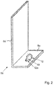
- Figure 2 shows part of a mounting device according to an embodiment of the present invention.
- the first fixing element 5a is now shown in detail in a perspective three-dimensional view.
- the longer leg is designated by reference number 8a 'and the shorter leg is referred to by reference number 8a.
- the length ratio in the cross section between the longer leg 8a 'and the shorter leg 8a is approximately between 1: 2 and 1: 3.
- connection 19 On the shorter leg 8a, two differently sized recesses 12, 12a are arranged, which are connected to one another via a connection 19.
- the two cutouts 12, 12a are partially and / or partially circular. Both centers of the cutouts 12, 12a lie on an axis which runs parallel to the longer side of the shorter leg 8a.
- the connection 19 also has a width that is smaller than the respective diameter of the cutouts 12, 12a. In other words, this represents a narrowing, constriction, a partial delimitation and / or a separation of the two cutouts from one another.
- the center point of the further cutout 12a is arranged in the middle of the shorter leg 8a.
- the larger recess 12 serves to insert part of the setting device 4, more precisely the control knob 11. This is first pressed or inserted into the recess 12 until the tapered area 11a of the control knob 11 is level with the further recess 12a and the connection 19 located. Then it is pressed laterally through the narrow point between the two recesses 12, 12a - connection 19 - into the smaller recess 12a.
- the tapered area 11a of the control knob 11, the width of the connection 19 and the smaller cutout 12a are designed such that the control knob 11 designed as a rotating body is essentially held captive in the smaller cutout 12a, i.e. a clamping device 10 by the elements 11 , 11a, 12, 12a, 19 is formed.
- the outer diameter of the tapered region 11a of the control knob 11 is chosen to be smaller than the inner diameter of the smaller recess 12a, but larger than the width of the connection 19.
- the inner diameter of the larger recess can be 7.2 mm
- control knob 11 can have an inner and / or outer entrainment profile on its underside, so that it can alternatively or additionally be actuated, for example, with a hexagon socket, a wrench or the like.
- steel in particular stainless steel
- the fixing elements 5a, 5b can serve as the material for the setting device 4 and the fixing elements 5a, 5b.
- the same also applies to the internal thread for the adjusting screw 9.
- the double-sided adhesive tape 7a, 7b, liquid adhesive, etc. can also be used.
- the assembly device, in particular the fixing elements 5a, 5b from plastic, for example as injection molded parts.
- Figure 3 shows part of a mounting device according to an embodiment of the present invention.
- FIG. 3 a further embodiment of the fixing element 5b, which cooperates with the receiving device 3 or can be connected, is shown, the viewing direction running along the installation direction 100 in the direction of the underside of the worktop 3.
- FIG. 3 Essentially, that shows Figure 3 a fixing element 5b according to Figure 1 .
- the fixing element 5b according to Figure 1 has the fixing element 5b according to Figure 3
- two drill holes 17 in which, for example, self-tapping screws can be used to connect the mounting device 1, more precisely the fixing element 5b, to the underside of the worktop 3.
- the fixing element 5b points in accordance with Figure 3 two spacers 18a, 18b, which are designed in particular for flat contact with the installation element 2.
- the two spacers 18a, 18b are separated here, but they can also extend in the form of a whole or only partially along the side of the fixing element 5b adjacent to the installation element 2.
- the spacers 18a, 18b can also be used for sufficiently flat contact Be L-shaped.
- the spacers 18a, 18b can be formed in one piece with the fixing element 5b or as separate parts. In the latter case, these can then be designed specifically for each installation element 2 and, for example, can be fixed on the fixing element 5b by means of a plug-in or clip connection, adhesive pads or surfaces or the like. This has the advantage that the fixing element 5b does not have to be completely adapted to the respective installation element 2, but only the corresponding spacers 18a, 18b.
- Figure 4 shows steps of a method according to an embodiment of the present invention.
- Figure 4 a method for installing an installation element in a receiving device along an installation direction by means of a mounting device according to one of claims 1-14.
- the process comprises the following steps:
- a first step S1 the installation element is inserted into the receiving device.
- step S2 the assembly device and the installation element are fixed to one another.
- step S3 the mounting device and the receiving device are fixed to one another.
- step S4 the relative position of the installation element and the receiving device is set such that a gap is formed in the direction of installation between the installation element and the receiving device in an overlap area that corresponds to the bearing surface of the installation element in the receiving device.
- a sealant in particular silicone, is introduced into the gap.
- step S6 the size of the gap is reduced by changing the relative position by means of the assembly device.
- Figure 5 shows a fixing element of a mounting device according to an embodiment of the present invention.
- Figure 5 essentially a fixing element 5a according to Figure 2 shown.
- the fixing element 5a is made in two parts with a first part 51 and a second part 52.
- Figure 5 shows in the upper part a plan view of the second part 52 parallel to the installation direction 100, in the lower part on the left a view of the fixing element 5a composed of the two parts 51, 52 perpendicular to the installation direction 100 with a plan view of the fixing surface 6a and in the lower part on the right a side view with a viewing direction perpendicular to the installation direction 100 and perpendicular to the fixing surface 6a.
- the first part 51 of the fixing element 5a is essentially plate-shaped and has two trapezoidal cutouts at its end facing the second part 52, which together with corresponding trapezoidal projections on the first part 51 have two dovetail connections 20a, 20b to provide a releasable form-fitting connection Allow 20 of the two parts 51, 52 to each other.
- the two parts 51, 52 can be made of sheet metal, for example.
- the fixing surface 6a of the fixing element 5a is provided here in particular exclusively by the first part 51.
- the second part 52 is L-shaped, the shorter end or the shorter leg of the L-shape comprising the trapezoidal projections for the dovetail connection 20.
- the shorter leg 8a of the fixing element 5a is thus formed exclusively by the second part 52, more precisely the longer leg of the L-shape of the second part 52.
- the longer leg 8a 'of the fixing element 5a is the shorter leg of the L-shape of the second Part 52 and formed by the first part 51.
- the thickness 152 of the second part 52 in particular in the region of the shorter leg of the L-shape of the second part 52, is smaller than the thickness 151 of the first part 51. This in particular prevents the two parts 51, 52 from tilting too much toward one another and thus a detachment of the two parts 51, 52 from each other.
- connection of the two parts 51, 52 can be secured or provided by a material and / or non-positive connection, for example an adhesive connection or the like.
- a material and / or non-positive connection for example an adhesive connection or the like.
- another form-fitting connection with a corresponding undercut can be used instead of or in combination with the dovetail connection 20.
- Figure 6 shows a mounting device according to an embodiment of the present invention schematically and in cross section.
- FIG 6 is essentially a mounting device 1 according to Figure 1 shown.
- a first fixing element 5a which is formed in two parts with a first substantially vertically oriented part 8a 'and a horizontally oriented part 8b.
- the first part 8a ' runs essentially vertically, a lower part 8a'-1 being connected to the installation element 2, and an upper part 8a'-2 being arranged at a distance from the installation element 2 by a horizontal offset 8c.
- the lower part 8a'-1 is as in Figure 1 described provided with a fixing surface 6a and fixed by means of a double-sided adhesive tape 7a to a partial area of the vertical edge 2a of the built-in element 2.
- the upper region 8a'-2 has two horizontal slots 8d-1, 8d-2 which are open from one side and into which the second part 8b engages as follows:
- the second part 8b has an essentially T-shaped profile.
- the head 8b ' is a square or rectangular plate - as in Figure 6 shown on the left - trained.
- the in Figure 6 horizontally extending leg of the T-shaped profile is designed to cooperate with the adjusting device 4.
- a section of the leg of the T-shaped profile is laterally inserted into one of the slots 8d-1, 8d-2 in accordance with the desired spacing or adjustment possibility of the adjusting device 4.
- the leg of the second part 8b forms in the horizontal plane - in Figure 6 left, plane perpendicular to the plane of the drawing parallel to the slots 8d-1, 8d-2 - also a surface, so that the leg 8b is secured against rotation about a horizontal axis.
- the horizontal offset 8c of the first part 8a 'and the horizontal thickness 153 of the head 8b' formed as a plate is dimensioned such that it is clamped between the installation element 2 and the upper part 8a'-2 and thus against tilting by one in Figure 6 horizontal axis on the right in the drawing plane is secured.
- the second fixing element 5b comprises, as in FIG Figure 1 an essentially horizontal area as a fixing surface 6b, on which a double-sided adhesive tape 7b is arranged, for fixing with the horizontally oriented area 3a of the underside of the worktop 3.
- the second fixing element 5b further has a set screw 9 "oriented in the vertical direction for vertical adjustment of the second fixing element 5b relative to the first fixing element 5a.
- the fixing surfaces 6a and 6b of the first fixing element 5a and the second fixing element 5b are rectangular here, in particular with an aspect ratio between 1: 1 and 1: 2, but other shapes are also, for example circular, trapezoidal, etc. The same applies accordingly to the aspect ratio or the edge lengths to one another.
- the second fixing element 5b together with the adjusting device 4 and the horizontal part 8b of the first fixing element 5a as a pre-assembled set and, on the other hand, to fix the vertical part 8a'-1 of the first fixing element 5a to the mounting element 2 already during production, for example. Since the thickness 153 is small, the distance between the worktop 3 and the built-in element 2 and thus the cutout in the worktop 3 for the built-in element 2 can also be kept as small as possible without the support surface 14 having a smaller size.
- At least one of the embodiments of the present invention enables an exact adjustable position of the built-in part and receiving device relative to one another. Another advantage is simple and inexpensive assembly and cost-effective production. Another advantage is the high flexibility with regard to possible areas of application.
Landscapes
- Engineering & Computer Science (AREA)
- Environmental & Geological Engineering (AREA)
- Health & Medical Sciences (AREA)
- Life Sciences & Earth Sciences (AREA)
- Hydrology & Water Resources (AREA)
- Public Health (AREA)
- Water Supply & Treatment (AREA)
- Connection Of Plates (AREA)
Applications Claiming Priority (2)
| Application Number | Priority Date | Filing Date | Title |
|---|---|---|---|
| DE102018217527 | 2018-10-12 | ||
| DE102019201198.5A DE102019201198A1 (de) | 2018-10-12 | 2019-01-30 | Montagesystem für ein Einbauelement |
Publications (1)
| Publication Number | Publication Date |
|---|---|
| EP3636841A1 true EP3636841A1 (fr) | 2020-04-15 |
Family
ID=67551103
Family Applications (1)
| Application Number | Title | Priority Date | Filing Date |
|---|---|---|---|
| EP19190133.9A Pending EP3636841A1 (fr) | 2018-10-12 | 2019-08-05 | Dispositif de montage pour un élément encastré |
Country Status (2)
| Country | Link |
|---|---|
| EP (1) | EP3636841A1 (fr) |
| DE (1) | DE102019201198A1 (fr) |
Families Citing this family (1)
| Publication number | Priority date | Publication date | Assignee | Title |
|---|---|---|---|---|
| DE102024116548A1 (de) | 2024-06-12 | 2025-12-18 | Blanco Gmbh + Co Kg | Montagevorrichtung für ein Sanitärbecken sowie Verfahren zum Bereitstellen eines Sanitärbeckens |
Citations (7)
| Publication number | Priority date | Publication date | Assignee | Title |
|---|---|---|---|---|
| US2495853A (en) * | 1946-02-27 | 1950-01-31 | Lindgren Hugo | Sink and drainboard structure |
| US2646575A (en) * | 1949-03-18 | 1953-07-28 | Luxene Inc | Sink and drainboard assembly |
| US2864099A (en) * | 1955-10-12 | 1958-12-16 | Church Of Religious Science | Sink mounting |
| US4432106A (en) * | 1982-06-23 | 1984-02-21 | Arro-Mac Manufacturing Inc. | Clamp assembly for self-rimming sinks or basins |
| WO2000052270A2 (fr) | 1999-03-04 | 2000-09-08 | Elkay Manufacturing Company | Procede de fixation d'un evier a un revetement de comptoir et procede d'utilisation correspondant |
| EP1772566A2 (fr) | 2005-10-05 | 2007-04-11 | Niro-Plan Ag | Elément à encastrer dans une cuisine |
| JP2016195664A (ja) | 2015-04-03 | 2016-11-24 | パナソニックIpマネジメント株式会社 | シンクの取付方法および取付構造 |
-
2019
- 2019-01-30 DE DE102019201198.5A patent/DE102019201198A1/de active Pending
- 2019-08-05 EP EP19190133.9A patent/EP3636841A1/fr active Pending
Patent Citations (7)
| Publication number | Priority date | Publication date | Assignee | Title |
|---|---|---|---|---|
| US2495853A (en) * | 1946-02-27 | 1950-01-31 | Lindgren Hugo | Sink and drainboard structure |
| US2646575A (en) * | 1949-03-18 | 1953-07-28 | Luxene Inc | Sink and drainboard assembly |
| US2864099A (en) * | 1955-10-12 | 1958-12-16 | Church Of Religious Science | Sink mounting |
| US4432106A (en) * | 1982-06-23 | 1984-02-21 | Arro-Mac Manufacturing Inc. | Clamp assembly for self-rimming sinks or basins |
| WO2000052270A2 (fr) | 1999-03-04 | 2000-09-08 | Elkay Manufacturing Company | Procede de fixation d'un evier a un revetement de comptoir et procede d'utilisation correspondant |
| EP1772566A2 (fr) | 2005-10-05 | 2007-04-11 | Niro-Plan Ag | Elément à encastrer dans une cuisine |
| JP2016195664A (ja) | 2015-04-03 | 2016-11-24 | パナソニックIpマネジメント株式会社 | シンクの取付方法および取付構造 |
Also Published As
| Publication number | Publication date |
|---|---|
| DE102019201198A1 (de) | 2020-04-16 |
Similar Documents
| Publication | Publication Date | Title |
|---|---|---|
| DE69516003T2 (de) | Konstruktionssystem mit vorgefertigten lochanordnungen | |
| DE2514357C3 (de) | Beschlag zum verschwenkbaren Verbinden einer Möbelplatte mit einem feststehenden Möbelteil | |
| EP1902814B1 (fr) | Kit de construction comprenant au moins un panneau | |
| EP2808457A2 (fr) | Dispositif d'écoulement d'eau pour une installation sanitaire, ainsi que douche à l'italienne | |
| EP0645957B1 (fr) | Ossature d'armoire | |
| EP0168672B1 (fr) | Porte d'appareil ménager encastrable avec panneau de porte | |
| EP0237768B1 (fr) | Dispositif d'assemblage spatial d'éléments | |
| EP3636841A1 (fr) | Dispositif de montage pour un élément encastré | |
| EP3549486B1 (fr) | Table de travail pour un système d'automatisation de laboratoire et système d'automatisation de laboratoire comprenant ladite table | |
| DE29717355U1 (de) | Bausatz zum modulartigen Aufbau einer aus drei Hauptmodulen aufgebauten Konsole | |
| EP1582802B1 (fr) | Support avec dispositif de fixation pour écran plat | |
| DE102011000196B4 (de) | Befestigungsvorrichtung | |
| DE102017008020B4 (de) | Modulare Wand | |
| DE9308162U1 (de) | Befestigungselement für einen Sockel eines Schaltschrankes | |
| EP3888497A1 (fr) | Dispositif de fixation d'un meuble à un support et procédé de fixation d'un corps de meuble à un support | |
| DE69813106T2 (de) | Vorrichtung zum gegenseitigen Verbinden flacher Elemente, insbesondere für den Zusammenbau von Möbelstücken | |
| EP1645756B1 (fr) | Élément d'attachement et de fixation pour un système pour l'établissement des dispositifs pour maintenir des objets | |
| EP4030103B1 (fr) | Plaque de cuisson avec boîtier de commande | |
| DE8011513U1 (de) | Sanitaer-objekt mit verdeckter wandbefestigung, wie z.b. seifenschale, glashalter, handtuchhalter, handtuchring, ablage u.dgl. | |
| EP1637749B1 (fr) | Dispositif de fixation avec vis | |
| DE102005013086B4 (de) | System, bestehend aus einer Sockelblende und einer Abdeckung | |
| EP4425002A1 (fr) | Raccord à vis | |
| DE19906571A1 (de) | Montageplatte für Funktionselemente | |
| DE19527855C1 (de) | Befestigungsvorrichtung für eine Auflagespüle | |
| AT501632B1 (de) | Vorrichtung zum befestigen eines fensterrahmens |
Legal Events
| Date | Code | Title | Description |
|---|---|---|---|
| PUAI | Public reference made under article 153(3) epc to a published international application that has entered the european phase |
Free format text: ORIGINAL CODE: 0009012 |
|
| STAA | Information on the status of an ep patent application or granted ep patent |
Free format text: STATUS: THE APPLICATION HAS BEEN PUBLISHED |
|
| AK | Designated contracting states |
Kind code of ref document: A1 Designated state(s): AL AT BE BG CH CY CZ DE DK EE ES FI FR GB GR HR HU IE IS IT LI LT LU LV MC MK MT NL NO PL PT RO RS SE SI SK SM TR |
|
| AX | Request for extension of the european patent |
Extension state: BA ME |
|
| STAA | Information on the status of an ep patent application or granted ep patent |
Free format text: STATUS: REQUEST FOR EXAMINATION WAS MADE |
|
| 17P | Request for examination filed |
Effective date: 20200929 |
|
| RBV | Designated contracting states (corrected) |
Designated state(s): AL AT BE BG CH CY CZ DE DK EE ES FI FR GB GR HR HU IE IS IT LI LT LU LV MC MK MT NL NO PL PT RO RS SE SI SK SM TR |
|
| STAA | Information on the status of an ep patent application or granted ep patent |
Free format text: STATUS: EXAMINATION IS IN PROGRESS |
|
| 17Q | First examination report despatched |
Effective date: 20210809 |