EP3636865A1 - Charnière pourvue de dispositif d'encliquetage pour la position zéro - Google Patents
Charnière pourvue de dispositif d'encliquetage pour la position zéro Download PDFInfo
- Publication number
- EP3636865A1 EP3636865A1 EP19201961.0A EP19201961A EP3636865A1 EP 3636865 A1 EP3636865 A1 EP 3636865A1 EP 19201961 A EP19201961 A EP 19201961A EP 3636865 A1 EP3636865 A1 EP 3636865A1
- Authority
- EP
- European Patent Office
- Prior art keywords
- latching
- locking
- recess
- guide
- roller
- Prior art date
- Legal status (The legal status is an assumption and is not a legal conclusion. Google has not performed a legal analysis and makes no representation as to the accuracy of the status listed.)
- Granted
Links
Images


Classifications
-
- E—FIXED CONSTRUCTIONS
- E05—LOCKS; KEYS; WINDOW OR DOOR FITTINGS; SAFES
- E05D—HINGES OR SUSPENSION DEVICES FOR DOORS, WINDOWS OR WINGS
- E05D11/00—Additional features or accessories of hinges
- E05D11/10—Devices for preventing movement between relatively-movable hinge parts
- E05D11/1014—Devices for preventing movement between relatively-movable hinge parts for maintaining the hinge in only one position, e.g. closed
-
- E—FIXED CONSTRUCTIONS
- E05—LOCKS; KEYS; WINDOW OR DOOR FITTINGS; SAFES
- E05D—HINGES OR SUSPENSION DEVICES FOR DOORS, WINDOWS OR WINGS
- E05D5/00—Construction of single parts, e.g. the parts for attachment
- E05D5/02—Parts for attachment, e.g. flaps
- E05D5/0246—Parts for attachment, e.g. flaps for attachment to glass panels
-
- E—FIXED CONSTRUCTIONS
- E05—LOCKS; KEYS; WINDOW OR DOOR FITTINGS; SAFES
- E05Y—INDEXING SCHEME ASSOCIATED WITH SUBCLASSES E05D AND E05F, RELATING TO CONSTRUCTION ELEMENTS, ELECTRIC CONTROL, POWER SUPPLY, POWER SIGNAL OR TRANSMISSION, USER INTERFACES, MOUNTING OR COUPLING, DETAILS, ACCESSORIES, AUXILIARY OPERATIONS NOT OTHERWISE PROVIDED FOR, APPLICATION THEREOF
- E05Y2201/00—Constructional elements; Accessories therefor
- E05Y2201/60—Suspension or transmission members; Accessories therefor
- E05Y2201/622—Suspension or transmission members elements
- E05Y2201/638—Cams; Ramps
-
- E—FIXED CONSTRUCTIONS
- E05—LOCKS; KEYS; WINDOW OR DOOR FITTINGS; SAFES
- E05Y—INDEXING SCHEME ASSOCIATED WITH SUBCLASSES E05D AND E05F, RELATING TO CONSTRUCTION ELEMENTS, ELECTRIC CONTROL, POWER SUPPLY, POWER SIGNAL OR TRANSMISSION, USER INTERFACES, MOUNTING OR COUPLING, DETAILS, ACCESSORIES, AUXILIARY OPERATIONS NOT OTHERWISE PROVIDED FOR, APPLICATION THEREOF
- E05Y2900/00—Application of doors, windows, wings or fittings thereof
- E05Y2900/10—Application of doors, windows, wings or fittings thereof for buildings or parts thereof
- E05Y2900/13—Type of wing
- E05Y2900/132—Doors
Definitions
- the invention relates to an articulated hinge, in particular for glass doors, with two hinge parts hingedly connected to one another about a swivel axis and with an adjustable latching device which has a latching body assigned to the first hinge part, linearly movably guided in a guide recess against the action of at least one spring element, and a latching roller assigned to the second hinge part with a locking recess cooperating with the locking body in a locking position, the locking roller being arranged coaxially to the swivel axis between two belt webs formed on the second belt part and being lockable in different angular positions of its locking recess
- Such a hinge which can be used for example for furniture doors or a glass door of a shower partition, is from the EP 0 822 309 B1 known.
- the closed position of the door hinged on the hinge can be adjusted by locking the locking roller arranged coaxially to the pivot axis between the two webs of the second hinge part with its locking recess so that the door has the desired closing or opening position relative to the wall or other wall elements, for example a shower, when the locking body is pressed by the spring element into the locking recess.
- the generic hinge is provided with a two-part axle bolt consisting of two bolt parts that can be screwed together, the locking roller being plugged onto one bolt part and the other bolt part being supported on the locking roller and countering it when the axle bolt parts are screwed together presses a band web on the second part of the band and thereby clamps it.
- a hinge with a locking device in which a supporting axis for the existing locking body is held by means of two separate holding elements which are guided in separate bores.
- the two holding elements can move towards each other and each center a single spring and at the same time one of the ends of the supporting axis, which is to prevent any contact between the metallic band parts and the supporting axis or the springs in order to minimize noise.
- the object of the invention is to provide a hinge that avoids the aforementioned disadvantages, improves tolerance compensation and better positions a door leaf in the desired position.
- the invention proposes that the first band part have a first guide recess for one has a first locking body and a second guide recess for a second locking body movable relative to the first locking body and both locking bodies cooperate with a locking roller, whereby according to the solution variants specified in claim 1 or claim 2, an offset in the angle of inclination of the guide recesses, an offset of the guide recesses relative to each other Pivot axis and / or an angular or axial offset of the respective locking recesses to each other in the closed position, an additional bracing between the at least two existing locking bodies and the associated locking recesses is achieved in the locking position.
- both guide recesses are arranged offset by an offset relative to one another and to the pivot axis, or if both latching recesses are offset relative to one another and offset to the pivot axis, whereby preferably the offset dimension is the same for both guide recesses or latching recesses.
- first latching body is arranged on a first slide which is guided in a linearly movable manner in the first guide recess and the second latching body is arranged on a second slide which is linearly guided in the second guide recess .
- Each slider is expediently guided against rotation in the associated guide recess due to its shape and / or has spring receptacles for at least two spring elements on its rear side in order to achieve a sufficient clamping force in the detent position.
- Each slide preferably has spring receptacles on its rear side for separate accommodation of the spring ends of 2 spring elements, 3 spring elements or 4 spring elements.
- each locking body consists of a locking roller which is rotatably mounted on a front of the associated slide. This creates a line pressure between the locking roller and locking roller and the rolling behavior of these two functional elements of the locking device is improved. It is particularly expedient if the latching roller is rotatably mounted on the front of the slider by means of a supporting axis.
- the guide recess has a guide section with an oval cross section and each slide has a slide section with an oval outer circumference, which is guided in the guide section with a clearance fit.
- the locking roller can in particular be formed in one piece and have a locking groove as a locking recess;
- the latching groove can have a first groove section and a second groove section which is arranged at an angle to the first groove section.
- both groove sections can then each have an arc-shaped groove base, the center of the circle of the first groove section and the center of the circle of the second groove section each being at an angle to the groove center line of the latching groove.
- the openings of the two guide recesses facing the locking roller can be in alignment with one another and the two guide recesses are formed with different inclination angles in the first band part. It is more advantageous if the two guide recesses are formed with different angles of inclination and at the same time the openings of both guide recesses are axially offset or laterally offset from the pivot axis, in particular in such a way that the slides continue to be radial Swivel axis are guided in the associated guide recess.
- the angular offset between the guide recesses and / or the angular offset between the latching recesses can be less than 5 °, preferably less than 3 °; It is particularly advantageous if the angular offset is in the range from 1 ° to 2.5 °.
- the locking roller is non-rotatably connected to a first bolt part of a multi-part hinge bolt and can be locked in a rotationally fixed manner relative to the strap webs of the second strap part by means of a second bolt part which can be screwed together with the first bolt part and a clamping sleeve.
- the locking can also be done in other ways known to those skilled in the art.
- a joint band according to the invention is shown overall with reference number 1.
- the hinge 1 has a first hinge part 10 and a second hinge part 20, which are connected to one another in an articulated manner by means of a hinge pin 2.
- the hinge part 20 is designed for attachment to a schematically indicated wall element 3 formed by a thick glass pane, whereas the hinge part 10 is attached to a schematically indicated glass door 4. It goes without saying that at least two hinges 1 are used per door, which are mounted at different heights.
- the assembly takes place on glass cutouts in the wall element 3 or the glass door 4, for which purpose a first pressure plate 5 is screwed through the glass cutout to the hinge part 20, and a separate pressure plate 6 is screwed to the hinge part 10, as is known per se to the person skilled in the art , which is why this will not be discussed further.
- the band part 10 has two band webs 11 projecting from the main body of the band part 10 for the swivel connection, and the band part 20 has two inner band webs 21 projecting from the main body thereof, each of which is provided with a bolt eye 16, 26 for the passage of the hinge pin 2.
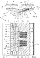
- the hinge 1 is additionally provided with a latching device, designated overall by reference numeral 30, with which a certain angular position between the wall element 3 and the glass door 4 can be set, for example an exact aligned one Alignment of the pane level of wall element 3 and glass door 4, as in Figure 1 indicated, wherein in this position the glass door 4 is held in position by means of the latching device 30.
- a latching device designated overall by reference numeral 30, with which a certain angular position between the wall element 3 and the glass door 4 can be set, for example an exact aligned one Alignment of the pane level of wall element 3 and glass door 4, as in Figure 1 indicated, wherein in this position the glass door 4 is held in position by means of the latching device 30.
- the essential functional elements of the latching device 30 are a latching roller 31 with a latching recess 32 on the circumference, and a slider 35A which is displaceably guided in a linear manner in a guide recess 12A in the first band part 10 and which is prestressed in the direction of the latching roller 31 by means of springs 36 and on its front side with a locking roller 37A rotatably mounted by means of a support roller 38 is provided as a locking body.
- the scope 38 is formed by a short axle pin.
- the locking roller 37A rolls with line pressure on the surface 33 of the locking roller 31 until the locking roller 37A can dip into the groove 32 in the preset position, as a result of which the glass door 4 is held in this position. In order to leave this position, a sufficiently large force must be applied to the glass door 4 for pivoting further that is sufficient to overcome the restoring force of the springs 36.
- the basic functional principle of such a locking device 30 is known to the person skilled in the art.
- a special feature according to the invention consists, in particular, of Figure 2 It can be clearly seen that two separate guide recesses 12A, 12B are formed in the first band part 10, a separate slide 35A, 35B, each with its own locking roller 37A, 37B, being arranged in each guide recess 12A, 12B.
- Each slide 35A, 35B is preloaded by means of three springs 36, and each spring 36 dips with its rear spring end into a blind hole 13 in the band part 10, whereas the front spring end dips into a blind hole 39 on the rear of the respective slide 35A, 35B.
- the individual springs 36 can therefore virtually not move relative to one another transversely to their spring axis and also cannot touch one another, apart from the necessary clearance to ensure assembly.
- the slider 35A can move largely independently of the slider 35B, even if the movement of both Slider 35A, 35B on the relative position between the locking roller 37A, 37B and the locking roller 31 is controlled positively.
- the height of the two separate sliders 35A, 35B with the separate latching rollers 37A, 37B acts on a single latching roller 31 that is common to both latching bodies.
- This latching roller 31 in turn has for both latching rollers 37A, 37B, that is to say the latching bodies of the latching device 30, each have a locking recess, which is formed in the exemplary embodiment shown by a locking groove 32 extending over the entire height of the locking roller 31; however, the groove profile of the locking groove 32 in the upper groove section 32A is different from that in the lower groove section 32B, the groove bottom of the one groove section 32A is therefore slightly different, namely offset from the groove bottom of the other groove section 32B.
- Figure 4 illustrates that the groove 32 is not uniformly continuous but has a groove section 32A which is designed slightly differently than the groove section 32B.
- the radius dimension of both radii of curvature R A , R B is the same, but the offset of the center points results in an angular offset ⁇ of the surfaces or the groove base of the groove sections 32A, 32B, which can be, for example, 2 °.
- a locking groove with groove sections 32A, 32B that are angled differently from one another can already be predetermined in the casting mold, for example, in the case of a locking roller 31 produced in the casting process.
- This angular offset by the dimension ⁇ of the two groove sections 32A, 32B or of the respective groove base 32A ', 32B' to one another has an advantageous effect when the latching device 30 engages, thus the glass door 4 assumes its desired position. Due to the angular offset of the two groove sections 32A, 32B with respect to one another, the two separate latching rollers 37A, 37B bear against the associated latching recess, that is to say the respective groove section 32A, 32B of the latching groove or its groove base, with a slight angle difference in the latching position; this causes an additional bracing or jamming, which can be used above all to compensate for manufacturing-related tolerances such as, for example, the guide play of the slides 35A, 35B in the associated guide recesses 12A, 12B.
- the zero position setting made possible with the locking device 30 is hereby significantly improved compared to known devices with zero position setting, since a door more precisely assumes the desired zero position even after several closing and opening operations and is also held in this position.
- the Figure 3 shows an articulated ligament 1 'which is basically identical in principle to the articulated ligament from FIGS Figures 1 and 2 .
- the band part 10 is of identical design as in the previous exemplary embodiment; the locking device 30 with the locking roller 31, the locking groove 32, and the separate sliders 35A, 35B, each of which rotatably supports a separate locking roller 37A, 37B, is identical to the previous exemplary embodiment.
- the two sliders 35A, 35B are U-shaped in the side view with a wide base web 39A, 39B, in which the blind holes for the spring ends of the springs 36 are formed from the rear.
- Each slider 35A, 35B has an oval cross section that extends over a predetermined depth of the slider 35A, 35B and forms a guide section for each slider.
- the oval cross section of the slide is matched to the oval cross section of the guide recesses 12A, 12B in the band part 10, but by means of a clearance fit between the outer contour of the slide 35A, 35B and the inner surface of the guide recesses 12A, 12B ensure that the respective slide 35A, 35B is linearly movable and at the same time guided with little noise.
- the band part 40 cooperating with the band part 10 is used here for fastening to a wall or any wall element not made of glass, which is why the band part 40 has the two inner band webs 41, between which the locking roller 31 is arranged, but otherwise only one fastening web 42 has through openings through which the fastening web 42 can be screwed to a wall. Due to the exploded view is in Figure 3 easy to see how the locking roller 31 and thus the position of the locking device 30 can be locked in a certain position.
- the position is determined by means of a divided axle bolt 2, which has a lower bolt part 7A, which extends over the height of all the band webs 11, 41, and a second bolt part 7B which can be screwed to it and which only consists of a fastening screw, which in turn interacts with a clamping sleeve 8 .
- the bolt part 7A has a bolt head 9, above which the bolt shaft of the bolt part 7A is provided with a knurling with which the hinge bolt on one of the two band webs 41 of the second band part 30, namely in the through bore of this band web 41, is rotationally fixed is fixed.
- the locking roller 31 remains rotatable about the bolt part 7A until the locking roller 31 is tensioned by means of the clamping sleeve 9 and the second bolt part 7B against the lower band web 41 with sufficient clamping force.
- a ribbed locking washer 49 serves as an additional anti-rotation element in the exemplary embodiment shown.
- the bolt part 7A is at least partially inserted through the through hole 34 in the locking roller 31 and the two upper band webs 11, 41. The security situation is therefore determined, as is this Figure 2 clarified very well, by tightening or clamping the locking roller 31 against the lower web 41 (or 21 in Figure 2 ) of the second hinge part 40.
- first hinge part 10 The free rotatability of the first hinge part 10 relative to the second hinge part 40 is ensured by means of sliding sleeves 45, 46, which each dip into the band webs 11 of the first hinge part 10 and a low-friction twisting of the hinge part 10 around the hinge pin 2 ensure that is rotatably connected to the second belt part 40 together with the locking roller 31.
- the Figure 7 illustrates the functional principle of the locking device in the embodiment of the Figures 1 to 3 .
- the two slides 35A, 35B are aligned one behind the other and the displacement movement in the guide recess takes place on the same radial line or displacement line V A, B. It is only because of the different groove sections 32A, 32B, that is to say the angular misalignment, or alternatively an axial misalignment, that the additional jamming or tensioning produced according to the invention results.
- the Figure 8 illustrates the principle of operation in an alternative embodiment of an articulated ligament, which is otherwise not shown with the exception of the locking device 130.
- the detent roller 131 has a uniform, continuous detent groove 132 in the detent device 130.
- the guide recesses for the two separate slides 135A, 135B are offset from one another at an angle; the displacement line V A for the slide 135A is inclined by half the offset angle ⁇ in one direction, and the displacement line V B for the other slide 135B is accordingly rotated by half the offset angle ⁇ in the other direction.
- both displacement lines V A , V B continue to lie on a radial line, that is, a line which intersect the pivot axis S, which coincides with the central axis of the locking roller 131; in relation to the band part, in which guide recesses are formed which are offset by half the angle ⁇ at an angle to the center plane, this means that the respective slide recesses are at an angle to one another and at an angle to the surface of the respective band part, which is why the respective springs 136A, 136B are also at an angle stand.
- the opening of the guide recess facing the locking roller 131 is then also slightly offset laterally with respect to a central plane of the associated band part in which the guide recesses are formed. Also through this This enables the clamping effect desired according to the invention and the improved tolerance compensation.
- Figure 9 shows yet another embodiment with reference to the locking device 230.
- the two guide recesses for the slides 235A, 235B are not aligned one behind the other symmetrically with a central plane of the associated band part, but are offset laterally to one another by an offset dimension X or laterally offset to a center line which in turn exactly intersects the pivot axis S, which in turn coincides with the central axis of the locking roller 231.
- the offset dimension X therefore corresponds to the distance between the two displacement lines V A , V B to one another and thus also to the extent by which the two guide recesses in the associated band part are offset from one another.
- Half the offset dimension X / 2 indicates the lateral offset of each guide recess for the respective slide 235A, 235B and the locking roller 237A, 237B guided with it relative to the pivot axis S.
- the respective springs 236A, 236B also experience the same offset.
- the angularly or laterally offset arrangement of the guide recesses can already be provided in the casting mold in the case of strip parts which are produced as a cast part. At most, the surfaces of the guide recesses would then have to be reworked.
- Clamping the locking roller with a split hinge pin is only one way in which the locking of the locking roller can be achieved.
- the number of springs, the shape of the slide and, accordingly, the shape of the guide recess can vary.
- the skewed arrangement of the guide recesses can be combined with a groove with differently shaped groove sections.
- a double locking roller could also be assigned to each of the slides.
- a locking ball could also be arranged on the respective slide as a locking body; a continuous locking groove does not necessarily have to be present on the locking roller, but rather the locking roller could also be only partially provided with an adapted locking recess on the circumference.
- the slides are preferably made of plastic, the springs are preferably spiral springs, as shown.
- the locking roller can also be composed of two rigidly connected individual rollers.
Landscapes
- Engineering & Computer Science (AREA)
- Mechanical Engineering (AREA)
- Closing And Opening Devices For Wings, And Checks For Wings (AREA)
- Pivots And Pivotal Connections (AREA)
- Hinge Accessories (AREA)
Applications Claiming Priority (1)
| Application Number | Priority Date | Filing Date | Title |
|---|---|---|---|
| DE202018105871.1U DE202018105871U1 (de) | 2018-10-12 | 2018-10-12 | Gelenkband mit Rastvorrichtung für Nulllage |
Publications (3)
| Publication Number | Publication Date |
|---|---|
| EP3636865A1 true EP3636865A1 (fr) | 2020-04-15 |
| EP3636865C0 EP3636865C0 (fr) | 2024-07-17 |
| EP3636865B1 EP3636865B1 (fr) | 2024-07-17 |
Family
ID=68242339
Family Applications (1)
| Application Number | Title | Priority Date | Filing Date |
|---|---|---|---|
| EP19201961.0A Active EP3636865B1 (fr) | 2018-10-12 | 2019-10-08 | Charnière pourvue de dispositif d'encliquetage pour la position zéro |
Country Status (2)
| Country | Link |
|---|---|
| EP (1) | EP3636865B1 (fr) |
| DE (1) | DE202018105871U1 (fr) |
Citations (7)
| Publication number | Priority date | Publication date | Assignee | Title |
|---|---|---|---|---|
| EP0822309A1 (fr) | 1996-08-01 | 1998-02-04 | Karl Loggen | Réglage d'arrêtoir pour pentures |
| EP0867586A2 (fr) | 1997-03-27 | 1998-09-30 | Stremler | Charnière pour portillon ou panneau pivotant, notamment pour panneau en verre |
| DE202007002494U1 (de) * | 2006-10-10 | 2007-05-16 | KL-Beschläge Karl Loggen GmbH | Gelenkband für Türen und Fenster |
| US20080083088A1 (en) * | 2006-10-06 | 2008-04-10 | Lin Kun Ta Industrial Co., Ltd. | Door hinge structure |
| DE102008018646B3 (de) | 2008-04-11 | 2009-11-19 | Pauli + Sohn Gmbh Metallwaren | Gelenkband |
| DE202009004853U1 (de) | 2009-05-25 | 2010-10-21 | Pauli + Sohn Gmbh Metallwaren | Pendeltürband |
| DE102012218168B3 (de) * | 2012-01-03 | 2013-06-20 | Dinmex Mfg., Inc. | Glastürscharnier |
Family Cites Families (1)
| Publication number | Priority date | Publication date | Assignee | Title |
|---|---|---|---|---|
| FR2874639B1 (fr) * | 2004-08-25 | 2006-12-08 | Stremler Soc Par Actions Simpl | Charniere a reglage angulaire |
-
2018
- 2018-10-12 DE DE202018105871.1U patent/DE202018105871U1/de active Active
-
2019
- 2019-10-08 EP EP19201961.0A patent/EP3636865B1/fr active Active
Patent Citations (7)
| Publication number | Priority date | Publication date | Assignee | Title |
|---|---|---|---|---|
| EP0822309A1 (fr) | 1996-08-01 | 1998-02-04 | Karl Loggen | Réglage d'arrêtoir pour pentures |
| EP0867586A2 (fr) | 1997-03-27 | 1998-09-30 | Stremler | Charnière pour portillon ou panneau pivotant, notamment pour panneau en verre |
| US20080083088A1 (en) * | 2006-10-06 | 2008-04-10 | Lin Kun Ta Industrial Co., Ltd. | Door hinge structure |
| DE202007002494U1 (de) * | 2006-10-10 | 2007-05-16 | KL-Beschläge Karl Loggen GmbH | Gelenkband für Türen und Fenster |
| DE102008018646B3 (de) | 2008-04-11 | 2009-11-19 | Pauli + Sohn Gmbh Metallwaren | Gelenkband |
| DE202009004853U1 (de) | 2009-05-25 | 2010-10-21 | Pauli + Sohn Gmbh Metallwaren | Pendeltürband |
| DE102012218168B3 (de) * | 2012-01-03 | 2013-06-20 | Dinmex Mfg., Inc. | Glastürscharnier |
Also Published As
| Publication number | Publication date |
|---|---|
| EP3636865C0 (fr) | 2024-07-17 |
| DE202018105871U1 (de) | 2020-01-16 |
| EP3636865B1 (fr) | 2024-07-17 |
Similar Documents
| Publication | Publication Date | Title |
|---|---|---|
| EP0259618B1 (fr) | Penture de porte et fenêtre, réglable pendant et après le montage | |
| AT6962U1 (de) | Scharnier | |
| DE3323403C2 (fr) | ||
| EP1653031B1 (fr) | Charnière de porte pliante | |
| EP2754813B1 (fr) | Charnière, notamment pour portes et fenêtres en plastique | |
| EP1411201A2 (fr) | Ferrure | |
| EP0478639A1 (fr) | Charniere. | |
| EP2149664B1 (fr) | Structure de support pour une charnière et charnière dotée d'une telle structure de support destinée à la fixation sur un vantail de porte | |
| DE20017995U1 (de) | Beschlag für Schiebetüren | |
| EP1577476B1 (fr) | Charnière pour maintenir de façon articulée une porte ou une fenêtre sur un cadre | |
| EP0837206A2 (fr) | Charnière de porte pour le support pivotant d'un vantail de porte sur un cadre de porte | |
| DE3920141C1 (fr) | ||
| EP3636865B1 (fr) | Charnière pourvue de dispositif d'encliquetage pour la position zéro | |
| EP1563152B1 (fr) | Charniere | |
| DE4229786C2 (de) | Sektionaltor oder Deckengliedertor | |
| DE2701979A1 (de) | Ecklager fuer fensterfluegel | |
| EP1512817B1 (fr) | Ferrure pour portes, fenêtres ou similaires | |
| DE2241208A1 (de) | Verstellbarer rollzapfen fuer fenster, tueren oder dergleichen | |
| AT412895B (de) | Halteelement zum halten einer führungsschiene für schiebetüren | |
| DE3301509C2 (de) | Ecklager für Drehkippflügel von Fenstern, Türen od.dgl. | |
| DE2131852B2 (de) | Klappenscharnier | |
| DE2551316A1 (de) | Ausstellvorrichtung, insbesondere fuer wahlweisen links- oder rechtsanschlag fuer fluegel von tueren, fenstern o.dgl. | |
| DE7709672U1 (de) | Verstellbares unteres ecklager fuer dreh-kipp-fluegel | |
| EP1612353B1 (fr) | Ensemble pivot pour un vantail moyen pivotable d'une fenêtre ou d'une porte à au moins trois vantails | |
| DE1434274C (de) | Ganzglasflügel mit einem Beschlag, welcher aus zwei fluchtend angeordneten Beschlagteilen besteht |
Legal Events
| Date | Code | Title | Description |
|---|---|---|---|
| PUAI | Public reference made under article 153(3) epc to a published international application that has entered the european phase |
Free format text: ORIGINAL CODE: 0009012 |
|
| STAA | Information on the status of an ep patent application or granted ep patent |
Free format text: STATUS: THE APPLICATION HAS BEEN PUBLISHED |
|
| AK | Designated contracting states |
Kind code of ref document: A1 Designated state(s): AL AT BE BG CH CY CZ DE DK EE ES FI FR GB GR HR HU IE IS IT LI LT LU LV MC MK MT NL NO PL PT RO RS SE SI SK SM TR |
|
| AX | Request for extension of the european patent |
Extension state: BA ME |
|
| STAA | Information on the status of an ep patent application or granted ep patent |
Free format text: STATUS: REQUEST FOR EXAMINATION WAS MADE |
|
| 17P | Request for examination filed |
Effective date: 20201015 |
|
| RBV | Designated contracting states (corrected) |
Designated state(s): AL AT BE BG CH CY CZ DE DK EE ES FI FR GB GR HR HU IE IS IT LI LT LU LV MC MK MT NL NO PL PT RO RS SE SI SK SM TR |
|
| STAA | Information on the status of an ep patent application or granted ep patent |
Free format text: STATUS: EXAMINATION IS IN PROGRESS |
|
| 17Q | First examination report despatched |
Effective date: 20210311 |
|
| GRAP | Despatch of communication of intention to grant a patent |
Free format text: ORIGINAL CODE: EPIDOSNIGR1 |
|
| STAA | Information on the status of an ep patent application or granted ep patent |
Free format text: STATUS: GRANT OF PATENT IS INTENDED |
|
| RIC1 | Information provided on ipc code assigned before grant |
Ipc: E05D 5/02 20060101ALN20240131BHEP Ipc: E05D 11/10 20060101AFI20240131BHEP |
|
| INTG | Intention to grant announced |
Effective date: 20240216 |
|
| GRAS | Grant fee paid |
Free format text: ORIGINAL CODE: EPIDOSNIGR3 |
|
| GRAA | (expected) grant |
Free format text: ORIGINAL CODE: 0009210 |
|
| STAA | Information on the status of an ep patent application or granted ep patent |
Free format text: STATUS: THE PATENT HAS BEEN GRANTED |
|
| AK | Designated contracting states |
Kind code of ref document: B1 Designated state(s): AL AT BE BG CH CY CZ DE DK EE ES FI FR GB GR HR HU IE IS IT LI LT LU LV MC MK MT NL NO PL PT RO RS SE SI SK SM TR |
|
| REG | Reference to a national code |
Ref country code: CH Ref legal event code: EP |
|
| REG | Reference to a national code |
Ref country code: DE Ref legal event code: R096 Ref document number: 502019011681 Country of ref document: DE |
|
| REG | Reference to a national code |
Ref country code: IE Ref legal event code: FG4D Free format text: LANGUAGE OF EP DOCUMENT: GERMAN |
|
| U01 | Request for unitary effect filed |
Effective date: 20240808 |
|
| U07 | Unitary effect registered |
Designated state(s): AT BE BG DE DK EE FI FR IT LT LU LV MT NL PT RO SE SI Effective date: 20240904 |
|
| U20 | Renewal fee for the european patent with unitary effect paid |
Year of fee payment: 6 Effective date: 20240919 |
|
| PG25 | Lapsed in a contracting state [announced via postgrant information from national office to epo] |
Ref country code: NO Free format text: LAPSE BECAUSE OF FAILURE TO SUBMIT A TRANSLATION OF THE DESCRIPTION OR TO PAY THE FEE WITHIN THE PRESCRIBED TIME-LIMIT Effective date: 20241017 |
|
| PG25 | Lapsed in a contracting state [announced via postgrant information from national office to epo] |
Ref country code: GR Free format text: LAPSE BECAUSE OF FAILURE TO SUBMIT A TRANSLATION OF THE DESCRIPTION OR TO PAY THE FEE WITHIN THE PRESCRIBED TIME-LIMIT Effective date: 20241018 Ref country code: PL Free format text: LAPSE BECAUSE OF FAILURE TO SUBMIT A TRANSLATION OF THE DESCRIPTION OR TO PAY THE FEE WITHIN THE PRESCRIBED TIME-LIMIT Effective date: 20240717 |
|
| PG25 | Lapsed in a contracting state [announced via postgrant information from national office to epo] |
Ref country code: IS Free format text: LAPSE BECAUSE OF FAILURE TO SUBMIT A TRANSLATION OF THE DESCRIPTION OR TO PAY THE FEE WITHIN THE PRESCRIBED TIME-LIMIT Effective date: 20241117 |
|
| PG25 | Lapsed in a contracting state [announced via postgrant information from national office to epo] |
Ref country code: HR Free format text: LAPSE BECAUSE OF FAILURE TO SUBMIT A TRANSLATION OF THE DESCRIPTION OR TO PAY THE FEE WITHIN THE PRESCRIBED TIME-LIMIT Effective date: 20240717 |
|
| PG25 | Lapsed in a contracting state [announced via postgrant information from national office to epo] |
Ref country code: ES Free format text: LAPSE BECAUSE OF FAILURE TO SUBMIT A TRANSLATION OF THE DESCRIPTION OR TO PAY THE FEE WITHIN THE PRESCRIBED TIME-LIMIT Effective date: 20240717 Ref country code: RS Free format text: LAPSE BECAUSE OF FAILURE TO SUBMIT A TRANSLATION OF THE DESCRIPTION OR TO PAY THE FEE WITHIN THE PRESCRIBED TIME-LIMIT Effective date: 20241017 |
|
| PG25 | Lapsed in a contracting state [announced via postgrant information from national office to epo] |
Ref country code: RS Free format text: LAPSE BECAUSE OF FAILURE TO SUBMIT A TRANSLATION OF THE DESCRIPTION OR TO PAY THE FEE WITHIN THE PRESCRIBED TIME-LIMIT Effective date: 20241017 Ref country code: PL Free format text: LAPSE BECAUSE OF FAILURE TO SUBMIT A TRANSLATION OF THE DESCRIPTION OR TO PAY THE FEE WITHIN THE PRESCRIBED TIME-LIMIT Effective date: 20240717 Ref country code: NO Free format text: LAPSE BECAUSE OF FAILURE TO SUBMIT A TRANSLATION OF THE DESCRIPTION OR TO PAY THE FEE WITHIN THE PRESCRIBED TIME-LIMIT Effective date: 20241017 Ref country code: IS Free format text: LAPSE BECAUSE OF FAILURE TO SUBMIT A TRANSLATION OF THE DESCRIPTION OR TO PAY THE FEE WITHIN THE PRESCRIBED TIME-LIMIT Effective date: 20241117 Ref country code: HR Free format text: LAPSE BECAUSE OF FAILURE TO SUBMIT A TRANSLATION OF THE DESCRIPTION OR TO PAY THE FEE WITHIN THE PRESCRIBED TIME-LIMIT Effective date: 20240717 Ref country code: GR Free format text: LAPSE BECAUSE OF FAILURE TO SUBMIT A TRANSLATION OF THE DESCRIPTION OR TO PAY THE FEE WITHIN THE PRESCRIBED TIME-LIMIT Effective date: 20241018 Ref country code: ES Free format text: LAPSE BECAUSE OF FAILURE TO SUBMIT A TRANSLATION OF THE DESCRIPTION OR TO PAY THE FEE WITHIN THE PRESCRIBED TIME-LIMIT Effective date: 20240717 |
|
| PG25 | Lapsed in a contracting state [announced via postgrant information from national office to epo] |
Ref country code: SM Free format text: LAPSE BECAUSE OF FAILURE TO SUBMIT A TRANSLATION OF THE DESCRIPTION OR TO PAY THE FEE WITHIN THE PRESCRIBED TIME-LIMIT Effective date: 20240717 |
|
| PG25 | Lapsed in a contracting state [announced via postgrant information from national office to epo] |
Ref country code: CZ Free format text: LAPSE BECAUSE OF FAILURE TO SUBMIT A TRANSLATION OF THE DESCRIPTION OR TO PAY THE FEE WITHIN THE PRESCRIBED TIME-LIMIT Effective date: 20240717 |
|
| PG25 | Lapsed in a contracting state [announced via postgrant information from national office to epo] |
Ref country code: SK Free format text: LAPSE BECAUSE OF FAILURE TO SUBMIT A TRANSLATION OF THE DESCRIPTION OR TO PAY THE FEE WITHIN THE PRESCRIBED TIME-LIMIT Effective date: 20240717 |
|
| PLBE | No opposition filed within time limit |
Free format text: ORIGINAL CODE: 0009261 |
|
| STAA | Information on the status of an ep patent application or granted ep patent |
Free format text: STATUS: NO OPPOSITION FILED WITHIN TIME LIMIT |
|
| REG | Reference to a national code |
Ref country code: CH Ref legal event code: PL |
|
| 26N | No opposition filed |
Effective date: 20250422 |
|
| GBPC | Gb: european patent ceased through non-payment of renewal fee |
Effective date: 20241017 |
|
| PG25 | Lapsed in a contracting state [announced via postgrant information from national office to epo] |
Ref country code: MC Free format text: LAPSE BECAUSE OF FAILURE TO SUBMIT A TRANSLATION OF THE DESCRIPTION OR TO PAY THE FEE WITHIN THE PRESCRIBED TIME-LIMIT Effective date: 20240717 |
|
| PG25 | Lapsed in a contracting state [announced via postgrant information from national office to epo] |
Ref country code: GB Free format text: LAPSE BECAUSE OF NON-PAYMENT OF DUE FEES Effective date: 20241017 |
|
| PG25 | Lapsed in a contracting state [announced via postgrant information from national office to epo] |
Ref country code: CH Free format text: LAPSE BECAUSE OF NON-PAYMENT OF DUE FEES Effective date: 20241031 |
|
| PG25 | Lapsed in a contracting state [announced via postgrant information from national office to epo] |
Ref country code: IE Free format text: LAPSE BECAUSE OF NON-PAYMENT OF DUE FEES Effective date: 20241008 |
|
| U20 | Renewal fee for the european patent with unitary effect paid |
Year of fee payment: 7 Effective date: 20250923 |
|
| PG25 | Lapsed in a contracting state [announced via postgrant information from national office to epo] |
Ref country code: CY Free format text: LAPSE BECAUSE OF FAILURE TO SUBMIT A TRANSLATION OF THE DESCRIPTION OR TO PAY THE FEE WITHIN THE PRESCRIBED TIME-LIMIT; INVALID AB INITIO Effective date: 20191008 |
|
| PG25 | Lapsed in a contracting state [announced via postgrant information from national office to epo] |
Ref country code: HU Free format text: LAPSE BECAUSE OF FAILURE TO SUBMIT A TRANSLATION OF THE DESCRIPTION OR TO PAY THE FEE WITHIN THE PRESCRIBED TIME-LIMIT; INVALID AB INITIO Effective date: 20191008 |