EP3636868B1 - Élément coulissant et procédé de montage d'un entraînement sur l'élément coulissant - Google Patents
Élément coulissant et procédé de montage d'un entraînement sur l'élément coulissant Download PDFInfo
- Publication number
- EP3636868B1 EP3636868B1 EP19201794.5A EP19201794A EP3636868B1 EP 3636868 B1 EP3636868 B1 EP 3636868B1 EP 19201794 A EP19201794 A EP 19201794A EP 3636868 B1 EP3636868 B1 EP 3636868B1
- Authority
- EP
- European Patent Office
- Prior art keywords
- drive
- sash
- sliding element
- rack
- fixed frame
- Prior art date
- Legal status (The legal status is an assumption and is not a legal conclusion. Google has not performed a legal analysis and makes no representation as to the accuracy of the status listed.)
- Active
Links
Images



Classifications
-
- E—FIXED CONSTRUCTIONS
- E05—LOCKS; KEYS; WINDOW OR DOOR FITTINGS; SAFES
- E05F—DEVICES FOR MOVING WINGS INTO OPEN OR CLOSED POSITION; CHECKS FOR WINGS; WING FITTINGS NOT OTHERWISE PROVIDED FOR, CONCERNED WITH THE FUNCTIONING OF THE WING
- E05F15/00—Power-operated mechanisms for wings
- E05F15/60—Power-operated mechanisms for wings using electrical actuators
- E05F15/603—Power-operated mechanisms for wings using electrical actuators using rotary electromotors
- E05F15/632—Power-operated mechanisms for wings using electrical actuators using rotary electromotors for horizontally-sliding wings
- E05F15/635—Power-operated mechanisms for wings using electrical actuators using rotary electromotors for horizontally-sliding wings operated by push-pull mechanisms, e.g. flexible or rigid rack-and-pinion arrangements
-
- E—FIXED CONSTRUCTIONS
- E05—LOCKS; KEYS; WINDOW OR DOOR FITTINGS; SAFES
- E05Y—INDEXING SCHEME ASSOCIATED WITH SUBCLASSES E05D AND E05F, RELATING TO CONSTRUCTION ELEMENTS, ELECTRIC CONTROL, POWER SUPPLY, POWER SIGNAL OR TRANSMISSION, USER INTERFACES, MOUNTING OR COUPLING, DETAILS, ACCESSORIES, AUXILIARY OPERATIONS NOT OTHERWISE PROVIDED FOR, APPLICATION THEREOF
- E05Y2201/00—Constructional elements; Accessories therefor
- E05Y2201/40—Motors; Magnets; Springs; Weights; Accessories therefor
- E05Y2201/43—Motors
-
- E—FIXED CONSTRUCTIONS
- E05—LOCKS; KEYS; WINDOW OR DOOR FITTINGS; SAFES
- E05Y—INDEXING SCHEME ASSOCIATED WITH SUBCLASSES E05D AND E05F, RELATING TO CONSTRUCTION ELEMENTS, ELECTRIC CONTROL, POWER SUPPLY, POWER SIGNAL OR TRANSMISSION, USER INTERFACES, MOUNTING OR COUPLING, DETAILS, ACCESSORIES, AUXILIARY OPERATIONS NOT OTHERWISE PROVIDED FOR, APPLICATION THEREOF
- E05Y2201/00—Constructional elements; Accessories therefor
- E05Y2201/60—Suspension or transmission members; Accessories therefor
- E05Y2201/622—Suspension or transmission members elements
- E05Y2201/71—Toothed gearing
- E05Y2201/716—Pinions
-
- E—FIXED CONSTRUCTIONS
- E05—LOCKS; KEYS; WINDOW OR DOOR FITTINGS; SAFES
- E05Y—INDEXING SCHEME ASSOCIATED WITH SUBCLASSES E05D AND E05F, RELATING TO CONSTRUCTION ELEMENTS, ELECTRIC CONTROL, POWER SUPPLY, POWER SIGNAL OR TRANSMISSION, USER INTERFACES, MOUNTING OR COUPLING, DETAILS, ACCESSORIES, AUXILIARY OPERATIONS NOT OTHERWISE PROVIDED FOR, APPLICATION THEREOF
- E05Y2201/00—Constructional elements; Accessories therefor
- E05Y2201/60—Suspension or transmission members; Accessories therefor
- E05Y2201/622—Suspension or transmission members elements
- E05Y2201/71—Toothed gearing
- E05Y2201/722—Racks
-
- E—FIXED CONSTRUCTIONS
- E05—LOCKS; KEYS; WINDOW OR DOOR FITTINGS; SAFES
- E05Y—INDEXING SCHEME ASSOCIATED WITH SUBCLASSES E05D AND E05F, RELATING TO CONSTRUCTION ELEMENTS, ELECTRIC CONTROL, POWER SUPPLY, POWER SIGNAL OR TRANSMISSION, USER INTERFACES, MOUNTING OR COUPLING, DETAILS, ACCESSORIES, AUXILIARY OPERATIONS NOT OTHERWISE PROVIDED FOR, APPLICATION THEREOF
- E05Y2400/00—Electronic control; Electrical power; Power supply; Power or signal transmission; User interfaces
- E05Y2400/65—Power or signal transmission
- E05Y2400/656—Power or signal transmission by travelling contacts
- E05Y2400/658—Power or signal transmission by travelling contacts with current rails
-
- E—FIXED CONSTRUCTIONS
- E05—LOCKS; KEYS; WINDOW OR DOOR FITTINGS; SAFES
- E05Y—INDEXING SCHEME ASSOCIATED WITH SUBCLASSES E05D AND E05F, RELATING TO CONSTRUCTION ELEMENTS, ELECTRIC CONTROL, POWER SUPPLY, POWER SIGNAL OR TRANSMISSION, USER INTERFACES, MOUNTING OR COUPLING, DETAILS, ACCESSORIES, AUXILIARY OPERATIONS NOT OTHERWISE PROVIDED FOR, APPLICATION THEREOF
- E05Y2600/00—Mounting or coupling arrangements for elements provided for in this subclass
- E05Y2600/40—Mounting location; Visibility of the elements
- E05Y2600/46—Mounting location; Visibility of the elements in or on the wing
-
- E—FIXED CONSTRUCTIONS
- E05—LOCKS; KEYS; WINDOW OR DOOR FITTINGS; SAFES
- E05Y—INDEXING SCHEME ASSOCIATED WITH SUBCLASSES E05D AND E05F, RELATING TO CONSTRUCTION ELEMENTS, ELECTRIC CONTROL, POWER SUPPLY, POWER SIGNAL OR TRANSMISSION, USER INTERFACES, MOUNTING OR COUPLING, DETAILS, ACCESSORIES, AUXILIARY OPERATIONS NOT OTHERWISE PROVIDED FOR, APPLICATION THEREOF
- E05Y2900/00—Application of doors, windows, wings or fittings thereof
- E05Y2900/10—Application of doors, windows, wings or fittings thereof for buildings or parts thereof
- E05Y2900/13—Type of wing
- E05Y2900/132—Doors
Definitions
- the present invention relates to a sliding element according to the preamble of claim 1 and a method for mounting a sliding door drive on the sliding element.
- a generic sliding element is from DE 10 2005 003301 A1 known.
- the solution to this problem is the object of the invention.
- both the mechanical drive component of the drive with the corresponding counter-drive component on the frame and the electrical contacts of the drive with the at least one or more busbar arrangement(s) on the frame is/are connectable.
- both the assembly of both the mechanical and the electrical components between the casement drive and the frame are carried out with a common assembly process - for example an adjustment process of the drive - which makes assembly quick, easy and safe.
- the invention also provides a method for installing a sash of a sliding element according to one of the claims relating thereto with a drive arranged thereon so that it can be adjusted in height on a window frame, in which the sash with the drive pre-installed on it is inserted into the window frame and in which then with just a single assembly process or - step - a height adjustment process - both the mechanical drive component of the drive and the electrical contacts of the drive with the corresponding counter-drive component on the frame and the at least one or more busbar arrangement (s) on the frame quickly and easily coupled will.
- the contacts are in the form of sliding contacts. It can also be provided that they are designed as compression spring contacts. This is advantageous but not mandatory. A different configuration of the contacts is also conceivable.
- the contacts are designed as sliding contacts, it is advantageous if they form at least one contact pincer or several contact pincers, which are then preferably arranged aligned in a row. Because contact tongs of this type can be arranged in a simple manner in such a way that they can be guided over the narrow sides of the busbar arrangements facing them in order to contact them. In this way, with a height adjustment of the drive with the contact tongs, the necessary electrical contact of the drive with the conductor rail arrangement, which can be connected to a higher-level energy supply device on the window frame or a power supply or the like, can be made easily during assembly.
- the housing of the drive is resiliently supported on the sash frame of the sash.
- a blind frame member having the toothed rack arrangement has a multi-function rail facing the casement with a multi-function contour facing the drive gear wheel, or that it is directly provided with such a multi-function contour.
- the multifunction contour has a fastening contour that is open in the direction of the rebate or in the direction of the sash, in particular a preferably undercut receiving groove for the toothed rack arrangement, into which the toothed rack arrangement is inserted.
- the conductor rail arrangement(s) each have a plastic rail as a carrier, which is coated on one side or on two sides with a conductive material, for example a conductor rail coating, extending in the sliding direction of the wing or in the x-direction (s) or is provided with one or more busbar strips, so that two busbars for applying different potentials are formed on the opposite sides of the plastic rail.
- these conductive materials for forming the busbars can also be formed on a plastic carrier material during an extrusion process (coextrusion).
- a conductive plastic or a metal, for example, are suitable as conductive materials.
- the drive housing is mounted parallel to a vertically aligned wing frame spar on this and is arranged with the device for height adjustment on this wing frame spar with limited height adjustment.
- the blind frame has the toothed rack arrangement as a mechanical counter-drive component, which has at least two or more toothed rack segments lined up next to one another, which are held together via a coupling element in such a way that a grid of the toothing of the toothed rack segments is continued via an interface of adjacent toothed rack segments if possibly, for example, a raster element may be missing in the transition area.
- a comb is used as the coupling element, which has a back and teeth protruding from the back. In this way, a grid that remains constant is also ensured over the several toothed rack segments in such a way that flawless, uniform operation of the drive is possible. It can be advantageously provided that the comb at a driven gear bridge-like over the interface of adjacent rack segments on the facing away from the drive side of the rack segments is set to couple them in the grid.
- the rack segments are designed as perforated rod segments. It can also be advantageous if a hole pattern or hole pattern arranged in the grid serves as a tooth system, with the teeth of the output gear wheel engaging in the hole grid, with the edges of the holes being bent over so that the web contours between the holes match the tooth contour of the Teeth of the output gear is adjusted. In this way, a particularly smooth running of the drive gear wheel on the toothed rack arrangement is guaranteed.
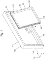
- FIG 1 shows a sliding element 10 with a sliding element blind frame 100 and a sliding leaf 20 arranged therein so that it can move linearly with an electric motor drive 300.
- Such constructions are often referred to as sliding doors.
- sliding element in the context of this document also includes sliding windows and sliding flaps and the like.
- the sliding element blind frame 100 - also called blind frame for short below - is oriented vertically here.
- the frame 100 has a first - here upper - horizontal frame member 101, a second - here lower horizontal frame member 102, a first - here left - vertical frame member 103 and a second - here right frame member 104.
- the window frame 100 essentially extends in an X/Y plane.
- the horizontal frame members 101, 102 are aligned parallel to the X-direction, the vertical frame members 103, 104 parallel to the Y-direction.
- the Z-direction extends perpendicularly thereto.
- the main plane of the window frame is parallel to the X/Y plane.
- the wing frame 200 has a first - here upper - horizontal wing frame spar 201, a second - here lower - horizontal wing frame spar 202, a first - here left - vertical wing frame spar 203 and a second - here right wing spar 204.
- Rolling or sliding means are not shown - typically on the lower wing frame spar - and the drive 300 for the wing frame 200, but in figure 2 and 3 is shown.
- the rollers already mentioned are preferably arranged at the bottom of the wing 20, so that the wing 20 can be moved back and forth or shifted rolling on the frame 100 (not shown here). This is a preferred embodiment but not a mandatory design requirement.
- the wing 20 is preferably driven at an upper end and held on the frame 100; however, this is also merely a preferred and not mandatory embodiment.
- the sash 20 is pivoted in direction A diagonally from bottom to top in the frame 100, so that its upper sash frame spar 101 can be brought into engagement with functional elements on this frame spar 101 using a drive 300 on the inside of the upper frame spar 100. and then screwed in at its lower end in direction B in the direction of the lower frame spar 102 so that it finally reaches the frame 100 after reaching a vertical orientation in direction C can be lowered slightly, so that its lower rollers or the like. Come to rest on the lower frame member 102 .
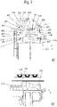
- the sash drive 300 is then adjusted so that it is brought into operational engagement with the window frame 100 precisely as desired. This is illustrated by the additional explanations yet to be given 2 and 3 .
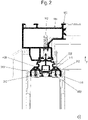
- the drive 300 has a housing 301 and an output gear 302.
- an electric motor and these downstream transmission elements and possibly control electronics are arranged, with the transmission elements in 2 indicated drive gear 301 belongs (in detail not recognizable here).
- the motor is preferably designed as a geared motor, which is advantageous but not essential. It is also conceivable--but less preferred--to design the motor and/or the transmission and/or the control electronics separately.
- the drive 300 has the output gear—here the output gear 302.
- the output gear 302 is intended to be engaged with a rack and pinion assembly 400 on the frame 100 and to roll thereon during operation. Since the drive 300 is arranged on the wing 200, this causes the output gear 302 to roll on the rack arrangement 400, so that the wing moves or shifts linearly in the window frame 100 when the output gear 302 rotates.
- the rack arrangement 400 is arranged in one of the frame members 101, which extend parallel to the X direction of movement. This is a horizontal direction.
- the toothed rack arrangement 400 is particularly preferably arranged in the upper horizontally oriented frame member 101 . Alternatively, however, it can also be arranged in the lower frame member 102 .
- the toothed rack arrangement 400 has several toothed rack segments 401, 402, which are held together by a coupling element 403 in such a way that the toothing or the toothed or hole grid 405 is continued (without interruption in the correct grid also via interfaces between adjacent toothed rack segments 401, 402. This will continue below in more detail in relation to the figures 4 and 5 described.
- the frame member 101 which has the toothed rack arrangement 400—in this case the upper one—can be designed in one piece or in several pieces.
- a multifunction rail 110 (see also 4 ) having a multifunction contour 111 directed towards the drive gear wheel - or is itself directly provided with such a multifunction contour 111 (the latter not shown here).
- the multifunction rail 111 is fastened to the upper frame member, here with screws 112 and/or further or other fastening means.
- the multifunction contour 111 has several functional areas. These include a fastening contour open in the direction of the fold or in the direction of the wing 20, in particular a preferably undercut receiving groove 112, for the rack arrangement 400, into which the rack arrangement 400 with its elements is inserted here in the X direction.
- toothed contour 405 directly in the multifunctional contour, in particular in the multifunctional rail, which is also referred to as a toothed rack arrangement 400 within the meaning of this application.
- the multifunctional contour 111 then has at least one fastening contour, in particular a fastening groove 113, in which a busbar arrangement 450 is fixed.
- a busbar arrangement 450 is fixed.
- the fastening contours - in particular fastening grooves 113 - for the conductor rail arrangements 450 can both be formed together side by side on one side - viewed perpendicularly to the main plane of the wing 20 - of the fastening contour, in particular receiving groove 112, for the toothed rack arrangement 400.
- the attachment contours - in particular attachment grooves 113 - for the busbar assemblies 450 can also alternatively be formed on opposite sides - viewed perpendicularly to the main plane of the wing - of the attachment contour, in particular receiving groove 112, for the toothed rack assembly 400.
- the toothed rack arrangement 400 is then advantageously in the middle between the two conductor rail arrangements 450, which does not necessarily have to be the case but is additionally advantageous for problem-free operation.
- the bus bar arrangement(s) 450 can be manufactured as purely metallic bars. However, it is also preferred that they each have a plastic busbar 451 as a carrier, which is provided on one side or on two sides with a busbar coating or a busbar strip extending in the x-direction. In this way, two busbars 452, 453 for applying different potentials can be formed on a busbar arrangement 450 in a simple manner on opposite sides of the plastic rail, which can be applied, for example, to different poles of a voltage supply device.
- the plastic rail 451 can have an anchoring foot 454 for anchoring in the fastening groove 113 and/or have an insertion aid, here an insertion tip 455 or an insertion wedge.
- the contacts 311, 312, which are preferably designed as sliding contacts each have conical sections or contact heads at the ends of spring arms, so that opposite conical contact heads, which can be spaced apart by a slot, have a kind of form corresponding insertion geometry for the insertion tip 455.
- contact arrangements 310 are formed from contacts for electrical contacting. These contact arrangements 310 can be configured in different ways. Here it is provided that they each have at least one sliding contact 311 or, as shown, two opposite sliding contacts 311, 312. Preferably, the sliding contacts 311, 312 are each designed as one or more compression spring contacts which, during operation, spring against the respective associated busbar 452, 453 press and slide/grind along it in a contacting manner.
- the design is thus such that the sliding contact or contacts 311, 312 slide along the busbars 451, 452 in a sliding manner when the sliding leaf 200 is displaced.
- the drives 400 arranged on the wing can be easily connected to a supply voltage and supplied with energy.
- the two or more sliding contacts 311, 312 can each form a spring-loaded contact pincer 313, which is designed in such a way that the sliding contacts 311, 312 press laterally against the respective busbars 452 and/or 453 from opposite sides with a spring force in order to to contact.
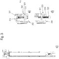
- a plurality of sliding contacts arranged one behind the other can also be provided on each side, which are then more or less in series. This is illustrated by the Figure 3a and b.
- the sliding contact arrangements 311, 312 are thus preferably designed in the manner of compression springs and preferably in the manner of tongs ( Figure 2a . c) .
- An energy supply unit is preferably connected to the busbars 452, 453 on the window frame (not shown), which in turn can be connected to a higher-level power supply system. Furthermore, it is also possible and preferable to transmit not only energy but also control signals via the busbars 451, 452. In this way, the drive 300 can be controlled, for example started and stopped and supplied with energy, and the direction of movement can also be reversed, for example. It is also conceivable to vary the speed of the drive 300 . Thus, according to a preferred embodiment, controlling signals are also transmitted, for example, which can be implemented electronically without any problems with a suitable design of controlling electronics, e.g. in a room or directly on the window frame and the control electronics of the drive 300.
- the busbar arrangements 450 are aligned here in the X/Y plane or in such a way that they can be swapped into the slots of the contact tongs 313 .
- the spring-loaded contact tongs 313 with the sliding contacts 311, 312 that come into contact with the busbar arrangements 450 are also slightly opened at the same time or almost at the same time, so that they hit the busbars 452, 453 of the busbar arrangement ( en) 450 slide so that you can safely make springy contact with them.
- the optional insertion aid on the conductor rail arrangement which can be formed, for example, by the tapered insertion tip 455 on the plastic rail 451.
- the drive can be supplied or acted upon with electrical energy and/or control signals using simple means and without the need to lay cables between the leaf 20 and the window frame.
- both the torque transmission means - the output gear 302 on the drive 300 on the sash 20 and the rack arrangement 400 on the frame 100 as well as the sliding contacts 311, 312 on the drive 300 on the wing 20 and the busbars 352, 353 on the frame 100 can be quickly and safely brought into functional engagement or brought into contact.
- the drive on the sash 20 is simultaneously mechanically coupled to the frame 100 and the drive on the sash 20 is electrically coupled to the frame 100 (see Fig Figure 2c ).
- the output gear 302 and the contact tongs 313 - as in 3 shown - be arranged on a here vertically upper narrow side/front side 301a of the drive housing 301 of the drive 300, which is or is fastened to one of the vertical wing frame bars 201-204. But this is not mandatory. Because the drive housing 301 could also be fastened to the upper horizontally running wing frame spar. But then the output gear 302 and the contact tongs 313 would also have to protrude laterally from the housing 301 (not shown here).
- the drive housing 301 is elongate here. It has the upper end face 301a, from which the output gear 302 and the sliding contacts 311, 312 protrude.
- a spring device 314 is provided, which can be embodied, for example, as a compression spring box.
- the drive housing 301 is preferably mounted parallel to the horizontal wing frame spar 302 on this. In this case, it is preferably provided that the drive housing 301 is arranged on this wing frame strut 302 so that it can be adjusted in height to a limited extent.
- a device 320 for adjusting the height of the drive in the vertical direction is used for this purpose. This facility can be designed in various ways. A possible embodiment shows the 3 .
- the device 320 has here first of all a support lug 321 which can be supported on the wing frame spar 204 or can also be formed in one piece with it.
- this support bracket is provided with a through hole 322 with an internal thread, through which a screw 323 is screwed, which presses against the housing 301 with its screw shank 324 from below, in particular via the spring device 314.
- the drive housing 301 engages at least one or more vertically extending grooves 326 on the vertical wing frame spar 304 with one or more vertically extending webs/protrusions 325 . This facilitates the height adjustment, since the respective web 325 can easily slide in the groove.
- a kind of clasp structure can also be formed in this way.
- the drive housing 300 can easily be preassembled on the window frame spar 202 in a somewhat vertically lower position. It is then only necessary to carry out the actual setting or height adjustment using device 320 for height adjustment until the mechanical drive components and the electrical contacts on drive 300 and on frame 100 are suitably engaged, in particular in the manner shown in Fig. 2a-c is shown.
- the device 302 for adjusting the height is realized in a structurally simple manner and the drive 300 can be easily mounted on the casement and the height of the drive 300 can be adjusted easily.
- the rack assembly 400 is now considered in more detail.
- a toothed rack arrangement 400 that is particularly easy to assemble and yet operates very reliably is created. This is based on the embodiment of the 4 and 5 describe in more detail.
- the toothed rack arrangement 400 has a plurality of toothed rack segments 401, 402 which are held together by a coupling element 403 is that the toothing or the tooth or hole grid 405 (without interruption in the correct grid also via interfaces of adjacent rack segments 401, 402 is continued.
- a type of comb is used as the coupling element 403, which has a back 406 and teeth 407 protruding from the back.
- the comb is set from the side opposite the output gear 102 in the manner of a bridge over the interface of adjacent toothed rack segments 401, 402 in order to couple them with grid accuracy.
- a pattern of holes or grid of holes 405 arranged in a grid serves here as a toothing, with the teeth of the output gear wheel 302 engaging in the grid of holes.
- a toothed rack can, for example, be produced in a simple manner from a sheet metal strip by means of a stamping/bending process.
- the edges of the holes 405a, 405b of the toothed rack segments 401 can additionally be easily bent in one direction, so that the web contours 408 between the holes 305a, 305b are particularly well adapted to the tooth contour of the teeth of the output gear 302.
- the perforated bar segments can be made of sheet metal. They can also be covered with a damping material, for example in the form of flocking or a coating, to dampen noise.
- troughs 409 are provided in the webs 408 on the side facing away from the output gear 302, into which the teeth of the coupling element 403 intervention. These troughs 409 are automatically formed in a simple manner, for example, with the production method for the perforated bar segments described in the previous paragraph. An engagement of the teeth of the output gear wheel 302 in the holes 305a, 305b is not impeded or not appreciably impeded in this way by the coupling element.
- the distance between the teeth 407 of the comb is then to be adjusted to the distance between these troughs 309 .
- it is possible to couple the rack segments 401, 402 in a simple manner with grid accuracy, without the rolling of the drive wheel 302 on the rack arrangement 40 being adversely affected.
- it enables excellent rolling on the rack arrangement 450, in which the transitions between the rack segments 401, 402 are not disadvantageously noticeable, even if, for example, a hole in the grid may be missing in the transition.
- the toothed rack arrangement 400 can be pushed into the multi-function rail 110 for the window frame profile at the front during pre-assembly.
- sliding element 10 frame 100 window frame bars 101 - 104 multifunctional rail 110 multifunction contour 111 receiving groove 112 mounting grooves 113 wing 20 sash frame 200 casement spar 201 - 204 drive 300 Housing 301 face 301a face 301b output gear 302 sliding contact arrangements 310 sliding contacts 311, 312 contact pliers 313 spring device 314 Device for height adjustment 320 support tab 321 through hole 322 screw 323 screw shank 324 rack arrangement 400 rack segments 401, 402 coupling element 403 Tooth or hole pattern 405 holes 405a, 405b the back 406 teeth 407 webs 408 Hopper 409 power rail arrangement 450 plastic splint 451 power rails 452,453 Top 454 insertion tip 455 directions A, B, C coordinate system X,Y,Z
Landscapes
- Power-Operated Mechanisms For Wings (AREA)
Claims (15)
- Élément coulissant (10) avec un châssis dormant (100) muni d'un longeron de châssis dormant inférieur (102) horizontal, d'un longeron de châssis dormant supérieur (101) horizontal et de montants de châssis dormant (103, 104) verticaux et avec un vantail (20) disposé avec possibilité de translation linéaire horizontale à l'aide d'un entraînement à moteur électrique (300), dans lequel l'entraînement à moteur électrique (300) est disposé sur le vantail et dans lequel l'entraînement (300) présente un composant mécanique d'entraînement pour se mettre en prise dans un composant d'entraînement opposé correspondant sur le châssis dormant (100), dans lequel l'entraînement présente en outre un ou plusieurs contacts (311, 312) pour la mise en contact conducteur électrique d'au moins une disposition ou de plusieurs dispositions de barre collectrice (450) sur le châssis dormant (100), dans lequel le composant d'entraînement de l'entraînement (300) sur le vantail (20) est conformé comme une roue dentée de sortie (302) et le composant d'entraînement opposé sur le châssis dormant (100) est conformé comme une disposition de crémaillère (400), caractérisé en ce que l'entraînement (300) est disposé de façon réglable verticalement en hauteur sur un châssis de vantail (200) du vantail (20), un dispositif étant prévu pour le réglage en hauteur de l'entraînement (300) par rapport au châssis de vantail (200) et permettant d'amener la roue dentée de sortie (302) et le ou les contacts (311, 312) de l'entraînement (300) en liaison active avec le dispositif de crémaillère et avec la ou les dispositions de barre collectrice (450) du châssis dormant (100) par le réglage vertical en hauteur.
- Élément coulissant selon la revendication 1, caractérisé en ce qu'il est conçu de telle manière qu'en une opération de montage de l'entraînement (300) qui est une opération de réglage en hauteur, le composant mécanique d'entraînement de l'entraînement (300) aussi bien que les contacts électriques (310, 311, 312) de l'entraînement (300) puissent être couplés avec le composant d'entraînement opposé -correspondant du châssis dormant (100) et avec l'au moins une ou les plusieurs dispositions de barre collectrice (350) du châssis dormant (100).
- Élément coulissant selon la revendication 1 ou 2, caractérisé en ce que les contacts sont conçus comme des contacts frotteurs (311, 312), de telle sorte que les contacts frotteurs (311, 312) présentent au moins une pince de contact (313) ou plusieurs pinces de contact.
- Élément coulissant selon l'une des revendications précédentes, caractérisé en ce que la roue dentée de sortie (302) et les contacts (311, 312) sont formés l'une à côté des autres sur un côté commun (301a) d'un boîtier (301) de l'entraînement (300), de préférence de telle manière que la roue dentée de sortie (302) et plusieurs rangées de contacts (311, 312) soient formées l'une à côté des autres sur le côté commun (301a) du boîtier (301) de l'entraînement (300) et/ou en ce que la roue dentée de sortie (302) est formée entre les plusieurs rangées de contact (311, 312) sur le côté commun (301a) du boîtier (301) de l'entraînement (300).
- Élément coulissant selon la revendication 4, caractérisé en ce que le boîtier (301) de l'entraînement (300) est appuyé de façon suspendue sur le châssis de vantail (200) du vantail (20).
- Élément coulissant selon l'une des revendications précédentes, caractérisé en ce qu'un longeron de châssis dormant (101) présentant la disposition de crémaillère (400) présente un rail multifonction (110) orienté vers le châssis de vantail (200) et muni d'un profil multifonction (111) ou en ce que le longeron de châssis dormant lui-même est directement pourvu d'un tel profil multifonction (111), de préférence de telle sorte que le profil multifonction (111) présente un profil de fixation ouvert en direction de la feuillure ou en direction du vantail (20), en particulier une gorge de logement (112) de préférence en contre-dépouille, pour la disposition de crémaillère (400), dans lequel la disposition de crémaillère (400) est introduite.
- Élément coulissant selon la revendication 6, caractérisé en ce que le profil multifonction (111) présente en outre un ou deux profils de fixation ouverts en direction de la feuillure ou en direction du vantail (20), en particulier une gorge de logement en contre-dépouille, pour une ou plusieurs dispositions de barre collectrice (450), dans lesquels la ou les dispositions de barre collectrice sont introduites, la ou les dispositions de barre collectrice (450) présentant de préférence chacune un rail en plastique (451) servant de support, qui est muni sur un ou deux côtés d'un matériau conducteur qui s'étend dans la direction des x, de sorte que deux barres collectrices (452, 453) sont formées sur les côtés opposés du rail en plastique pour l'application de potentiels différents.
- Élément coulissant selon l'une des revendications précédentes, caractérisé en ce que les barres collectrices (451, 452) et les contacts peuvent acheminer ou acheminent aussi bien de l'énergie motrice que des signaux de commande pour l'entraînement (300).
- Élément coulissant selon l'une des revendications 4 à 5, caractérisé en ce que le boîtier d'entraînement (301) est monté sur un montant du châssis de vantail (302) vertical parallèlement à celui-ci et disposé de façon réglable en hauteur dans les limites du dispositif (320) de réglage en hauteur sur ce montant de châssis de vantail (302), de préférence de telle façon que le dispositif (320) pour le réglage en hauteur de l'entraînement agisse sur l'entraînement (300) par l'intermédiaire d'un dispositif de ressort.
- Élément coulissant selon la revendication 9, caractérisé en ce que le boîtier d'entraînement (301) se met en prise par une ou plusieurs nervures/saillies (325) verticales dans au moins une ou plusieurs gorges (326) verticales du montant de châssis de vantail (304) vertical.
- Élément coulissant selon l'une des revendications précédentes, caractérisé en ce que le châssis dormant (100) présente comme composant d'entraînement opposé mécanique une ou la disposition de crémaillère (400), qui présente au moins deux ou plusieurs segments de crémaillère (401, 402) alignés les uns avec les autres, qui sont retenus ensembles par un élément de couplage (403) de telle manière qu'une matrice de la denture des segments de crémaillère soit reprise par une interface de segments de crémaillère (401, 402) voisins.
- Élément coulissant selon la revendication 11, caractérisé en ce que l'élément de couplage (403) est conformé comme un peigne qui présente un dos (406) et des dents (407) dépassant du dos, de préférence de telle sorte que sur un côté opposé à une roue dentée de sortie (102), le peigne relie les extrémités de segments de crémaillère (401, 402) voisins pour les coupler dans une matrice.
- Élément coulissant selon la revendication 12, caractérisé en ce que les segments de crémaillère (401,402) sont conformés comme des segments de barre perforée, de préférence de telle façon qu'une matrice de trous ou une grille de trous (405) disposée dans l'engrènement sert de matrice, les dents de la roue d'entraînement (302) se mettant en prise dans la matrice de trous, les bords des trous (405a, 405b) étant incurvés de telle manière que les profils des nervures (408) entre les trous (305a, 305b) soient adaptés aux profils des dents de la roue dentée de sortie (302) et/ou en ce que sont formées dans les nervures (408) entre des trous (405a, 405b) voisins dans lesquels les dents de la roue dentée de sortie (302) de l'entraînement (300) se mettent en prise des cuvettes (409) sur la face tournée à l'opposé de la roue dentée de sortie (302), dans lesquelles les dents de l'élément de couplage (403) se mettent en prise.
- Élément coulissant selon l'une des revendications 6 à 11 et 12 ou 13, caractérisé en ce que la disposition de crémaillère (400) est enfilée par la face d'extrémité dans le rail multifonction (110) pour le profilé de châssis dormant.
- Procédé de montage sur un châssis dormant (100) d'un vantail (20) d'un élément coulissant selon l'une des revendications précédentes muni d'un entraînement (200) disposé de façon réglable verticalement en hauteur, caractérisé en ce que le vantail (20) est inséré avec l'entraînement (300) préassemblé dans le châssis dormant (100) et en ce qu'aussi bien le composant mécanique de l'entraînement (300) que les contacts électriques (310, 311, 312) de l'entraînement (300) sont couplés avec l'élément d'entraînement opposé correspondant du châssis dormant (100) et avec l'au moins une ou les plusieurs dispositions de barre collectrice (350) du châssis dormant (100) en une seule opération de montage qui est une opération de réglage en hauteur.
Applications Claiming Priority (1)
| Application Number | Priority Date | Filing Date | Title |
|---|---|---|---|
| DE102018124854.7A DE102018124854A1 (de) | 2018-10-09 | 2018-10-09 | Schiebeelement und Verfahren zur Montage eines Antriebs an dem Schiebeelement |
Publications (2)
| Publication Number | Publication Date |
|---|---|
| EP3636868A1 EP3636868A1 (fr) | 2020-04-15 |
| EP3636868B1 true EP3636868B1 (fr) | 2022-07-20 |
Family
ID=68172141
Family Applications (1)
| Application Number | Title | Priority Date | Filing Date |
|---|---|---|---|
| EP19201794.5A Active EP3636868B1 (fr) | 2018-10-09 | 2019-10-07 | Élément coulissant et procédé de montage d'un entraînement sur l'élément coulissant |
Country Status (4)
| Country | Link |
|---|---|
| EP (1) | EP3636868B1 (fr) |
| DE (1) | DE102018124854A1 (fr) |
| ES (1) | ES2927502T3 (fr) |
| PL (1) | PL3636868T3 (fr) |
Family Cites Families (6)
| Publication number | Priority date | Publication date | Assignee | Title |
|---|---|---|---|---|
| DE19880977B4 (de) * | 1997-07-15 | 2012-08-02 | Geze Gmbh | Automatische Tür- oder Fensteranlage |
| DE102005003301A1 (de) * | 2005-01-24 | 2006-07-27 | Dorma Gmbh + Co. Kg | Schiebeflügel |
| DE102006054927A1 (de) * | 2006-11-22 | 2008-07-31 | BLASI - GMBH Automatische Türanlagen | Schiebetür |
| DE202011001541U1 (de) * | 2011-01-16 | 2011-03-31 | Ginzel, Lothar, Dipl.-Ing. | Schiebetür |
| ITTV20120107A1 (it) * | 2012-06-04 | 2013-12-05 | Nice Spa | Azionamento elettromeccanico per portone di garage |
| DE202018001610U1 (de) * | 2018-03-27 | 2018-04-13 | Siegenia-Aubi Kg | Antriebsvorrichtung mit einem Zahnstangenelement für einen verschiebbaren Flügel als Schiebeflügel oder verschiebbaren Hebe-Schiebeflügel eines Fensters oder einer Tür |
-
2018
- 2018-10-09 DE DE102018124854.7A patent/DE102018124854A1/de not_active Withdrawn
-
2019
- 2019-10-07 PL PL19201794.5T patent/PL3636868T3/pl unknown
- 2019-10-07 EP EP19201794.5A patent/EP3636868B1/fr active Active
- 2019-10-07 ES ES19201794T patent/ES2927502T3/es active Active
Also Published As
| Publication number | Publication date |
|---|---|
| PL3636868T3 (pl) | 2022-11-21 |
| ES2927502T3 (es) | 2022-11-07 |
| DE102018124854A1 (de) | 2020-04-09 |
| EP3636868A1 (fr) | 2020-04-15 |
Similar Documents
| Publication | Publication Date | Title |
|---|---|---|
| AT509796B1 (de) | Hohlprofil | |
| WO2000055460A1 (fr) | Dispositif tampon | |
| EP3498951A1 (fr) | Unité de poignée de porte | |
| EP2927409B1 (fr) | Joint pour une porte coulissante | |
| EP3045628B1 (fr) | Dispositif de bande de roulement pour le stockage mobile d'au moins un premier chariot à roulettes et d'au moins un second chariot à roulettes | |
| WO2019141836A1 (fr) | Module lève-vitre à deux coulisses de guidage pour le réglage d'un élément de raccordement raccordé à une vitre | |
| EP2754805A2 (fr) | Tringle de verrouillage pour une crémone | |
| DE202004011539U1 (de) | Band für Türen, Fenster u.dgl. | |
| EP2453097B1 (fr) | Porte sectionnelle latérale avec dispositif de verrouillage | |
| AT523302B1 (de) | Anordnung mit einem Möbelscharnier und einer Abdeckung | |
| EP3636868A1 (fr) | Élément coulissant et procédé de montage d'un entraînement sur l'élément coulissant | |
| EP2759666B1 (fr) | Ferrure avec élément de profilé | |
| EP3583283B1 (fr) | Porte | |
| EP2754803A2 (fr) | Crémone de fenêtre ou de porte | |
| EP2708693B1 (fr) | Cadre de battant ouvrant-coulissant | |
| EP1678402B1 (fr) | Dispositif pour recevoir le poids d'une porte a un ou deux vantaux d'une armoire electrique | |
| EP1898041B1 (fr) | Procedé et dispositif de montage d'accessoires sur cadres de bâtiments | |
| DE19913306A1 (de) | Beschlagsystem | |
| EP4215709A1 (fr) | Baguette d'étanchéité pour un cadre composé de profilés individuels de cadre d'une fenêtre, d'une porte ou d'une façade | |
| DE8800862U1 (de) | Schiebetür | |
| EP3786405A1 (fr) | Entraînement de meuble permettant de déplacer un élément de meuble monté mobile | |
| EP0006439B1 (fr) | Dispositif de chevauchement d'un joint entre deux têtières | |
| DE2461228A1 (de) | Verschlussvorrichtung fuer fenster, tueren oder dergleichen | |
| DE102022205376B4 (de) | Gleitschiene für einen Türantrieb | |
| EP1780363A2 (fr) | Porte |
Legal Events
| Date | Code | Title | Description |
|---|---|---|---|
| PUAI | Public reference made under article 153(3) epc to a published international application that has entered the european phase |
Free format text: ORIGINAL CODE: 0009012 |
|
| STAA | Information on the status of an ep patent application or granted ep patent |
Free format text: STATUS: THE APPLICATION HAS BEEN PUBLISHED |
|
| AK | Designated contracting states |
Kind code of ref document: A1 Designated state(s): AL AT BE BG CH CY CZ DE DK EE ES FI FR GB GR HR HU IE IS IT LI LT LU LV MC MK MT NL NO PL PT RO RS SE SI SK SM TR |
|
| AX | Request for extension of the european patent |
Extension state: BA ME |
|
| STAA | Information on the status of an ep patent application or granted ep patent |
Free format text: STATUS: REQUEST FOR EXAMINATION WAS MADE |
|
| 17P | Request for examination filed |
Effective date: 20201015 |
|
| RBV | Designated contracting states (corrected) |
Designated state(s): AL AT BE BG CH CY CZ DE DK EE ES FI FR GB GR HR HU IE IS IT LI LT LU LV MC MK MT NL NO PL PT RO RS SE SI SK SM TR |
|
| STAA | Information on the status of an ep patent application or granted ep patent |
Free format text: STATUS: EXAMINATION IS IN PROGRESS |
|
| 17Q | First examination report despatched |
Effective date: 20210111 |
|
| GRAP | Despatch of communication of intention to grant a patent |
Free format text: ORIGINAL CODE: EPIDOSNIGR1 |
|
| STAA | Information on the status of an ep patent application or granted ep patent |
Free format text: STATUS: GRANT OF PATENT IS INTENDED |
|
| INTG | Intention to grant announced |
Effective date: 20211215 |
|
| GRAJ | Information related to disapproval of communication of intention to grant by the applicant or resumption of examination proceedings by the epo deleted |
Free format text: ORIGINAL CODE: EPIDOSDIGR1 |
|
| STAA | Information on the status of an ep patent application or granted ep patent |
Free format text: STATUS: EXAMINATION IS IN PROGRESS |
|
| GRAS | Grant fee paid |
Free format text: ORIGINAL CODE: EPIDOSNIGR3 |
|
| INTC | Intention to grant announced (deleted) | ||
| STAA | Information on the status of an ep patent application or granted ep patent |
Free format text: STATUS: GRANT OF PATENT IS INTENDED |
|
| GRAP | Despatch of communication of intention to grant a patent |
Free format text: ORIGINAL CODE: EPIDOSNIGR1 |
|
| GRAA | (expected) grant |
Free format text: ORIGINAL CODE: 0009210 |
|
| STAA | Information on the status of an ep patent application or granted ep patent |
Free format text: STATUS: THE PATENT HAS BEEN GRANTED |
|
| INTG | Intention to grant announced |
Effective date: 20220527 |
|
| AK | Designated contracting states |
Kind code of ref document: B1 Designated state(s): AL AT BE BG CH CY CZ DE DK EE ES FI FR GB GR HR HU IE IS IT LI LT LU LV MC MK MT NL NO PL PT RO RS SE SI SK SM TR |
|
| REG | Reference to a national code |
Ref country code: CH Ref legal event code: EP |
|
| REG | Reference to a national code |
Ref country code: DE Ref legal event code: R096 Ref document number: 502019005005 Country of ref document: DE |
|
| REG | Reference to a national code |
Ref country code: AT Ref legal event code: REF Ref document number: 1505622 Country of ref document: AT Kind code of ref document: T Effective date: 20220815 |
|
| REG | Reference to a national code |
Ref country code: IE Ref legal event code: FG4D Free format text: LANGUAGE OF EP DOCUMENT: GERMAN |
|
| REG | Reference to a national code |
Ref country code: ES Ref legal event code: FG2A Ref document number: 2927502 Country of ref document: ES Kind code of ref document: T3 Effective date: 20221107 |
|
| REG | Reference to a national code |
Ref country code: LT Ref legal event code: MG9D |
|
| REG | Reference to a national code |
Ref country code: NL Ref legal event code: MP Effective date: 20220720 |
|
| PG25 | Lapsed in a contracting state [announced via postgrant information from national office to epo] |
Ref country code: SE Free format text: LAPSE BECAUSE OF FAILURE TO SUBMIT A TRANSLATION OF THE DESCRIPTION OR TO PAY THE FEE WITHIN THE PRESCRIBED TIME-LIMIT Effective date: 20220720 Ref country code: RS Free format text: LAPSE BECAUSE OF FAILURE TO SUBMIT A TRANSLATION OF THE DESCRIPTION OR TO PAY THE FEE WITHIN THE PRESCRIBED TIME-LIMIT Effective date: 20220720 Ref country code: PT Free format text: LAPSE BECAUSE OF FAILURE TO SUBMIT A TRANSLATION OF THE DESCRIPTION OR TO PAY THE FEE WITHIN THE PRESCRIBED TIME-LIMIT Effective date: 20221121 Ref country code: NO Free format text: LAPSE BECAUSE OF FAILURE TO SUBMIT A TRANSLATION OF THE DESCRIPTION OR TO PAY THE FEE WITHIN THE PRESCRIBED TIME-LIMIT Effective date: 20221020 Ref country code: NL Free format text: LAPSE BECAUSE OF FAILURE TO SUBMIT A TRANSLATION OF THE DESCRIPTION OR TO PAY THE FEE WITHIN THE PRESCRIBED TIME-LIMIT Effective date: 20220720 Ref country code: LV Free format text: LAPSE BECAUSE OF FAILURE TO SUBMIT A TRANSLATION OF THE DESCRIPTION OR TO PAY THE FEE WITHIN THE PRESCRIBED TIME-LIMIT Effective date: 20220720 Ref country code: LT Free format text: LAPSE BECAUSE OF FAILURE TO SUBMIT A TRANSLATION OF THE DESCRIPTION OR TO PAY THE FEE WITHIN THE PRESCRIBED TIME-LIMIT Effective date: 20220720 Ref country code: FI Free format text: LAPSE BECAUSE OF FAILURE TO SUBMIT A TRANSLATION OF THE DESCRIPTION OR TO PAY THE FEE WITHIN THE PRESCRIBED TIME-LIMIT Effective date: 20220720 |
|
| PG25 | Lapsed in a contracting state [announced via postgrant information from national office to epo] |
Ref country code: IS Free format text: LAPSE BECAUSE OF FAILURE TO SUBMIT A TRANSLATION OF THE DESCRIPTION OR TO PAY THE FEE WITHIN THE PRESCRIBED TIME-LIMIT Effective date: 20221120 Ref country code: HR Free format text: LAPSE BECAUSE OF FAILURE TO SUBMIT A TRANSLATION OF THE DESCRIPTION OR TO PAY THE FEE WITHIN THE PRESCRIBED TIME-LIMIT Effective date: 20220720 Ref country code: GR Free format text: LAPSE BECAUSE OF FAILURE TO SUBMIT A TRANSLATION OF THE DESCRIPTION OR TO PAY THE FEE WITHIN THE PRESCRIBED TIME-LIMIT Effective date: 20221021 |
|
| REG | Reference to a national code |
Ref country code: DE Ref legal event code: R097 Ref document number: 502019005005 Country of ref document: DE |
|
| PG25 | Lapsed in a contracting state [announced via postgrant information from national office to epo] |
Ref country code: SM Free format text: LAPSE BECAUSE OF FAILURE TO SUBMIT A TRANSLATION OF THE DESCRIPTION OR TO PAY THE FEE WITHIN THE PRESCRIBED TIME-LIMIT Effective date: 20220720 Ref country code: RO Free format text: LAPSE BECAUSE OF FAILURE TO SUBMIT A TRANSLATION OF THE DESCRIPTION OR TO PAY THE FEE WITHIN THE PRESCRIBED TIME-LIMIT Effective date: 20220720 Ref country code: DK Free format text: LAPSE BECAUSE OF FAILURE TO SUBMIT A TRANSLATION OF THE DESCRIPTION OR TO PAY THE FEE WITHIN THE PRESCRIBED TIME-LIMIT Effective date: 20220720 Ref country code: CZ Free format text: LAPSE BECAUSE OF FAILURE TO SUBMIT A TRANSLATION OF THE DESCRIPTION OR TO PAY THE FEE WITHIN THE PRESCRIBED TIME-LIMIT Effective date: 20220720 |
|
| PLBE | No opposition filed within time limit |
Free format text: ORIGINAL CODE: 0009261 |
|
| STAA | Information on the status of an ep patent application or granted ep patent |
Free format text: STATUS: NO OPPOSITION FILED WITHIN TIME LIMIT |
|
| PG25 | Lapsed in a contracting state [announced via postgrant information from national office to epo] |
Ref country code: SK Free format text: LAPSE BECAUSE OF FAILURE TO SUBMIT A TRANSLATION OF THE DESCRIPTION OR TO PAY THE FEE WITHIN THE PRESCRIBED TIME-LIMIT Effective date: 20220720 Ref country code: MC Free format text: LAPSE BECAUSE OF FAILURE TO SUBMIT A TRANSLATION OF THE DESCRIPTION OR TO PAY THE FEE WITHIN THE PRESCRIBED TIME-LIMIT Effective date: 20220720 Ref country code: EE Free format text: LAPSE BECAUSE OF FAILURE TO SUBMIT A TRANSLATION OF THE DESCRIPTION OR TO PAY THE FEE WITHIN THE PRESCRIBED TIME-LIMIT Effective date: 20220720 |
|
| 26N | No opposition filed |
Effective date: 20230421 |
|
| PG25 | Lapsed in a contracting state [announced via postgrant information from national office to epo] |
Ref country code: LU Free format text: LAPSE BECAUSE OF NON-PAYMENT OF DUE FEES Effective date: 20221007 Ref country code: AL Free format text: LAPSE BECAUSE OF FAILURE TO SUBMIT A TRANSLATION OF THE DESCRIPTION OR TO PAY THE FEE WITHIN THE PRESCRIBED TIME-LIMIT Effective date: 20220720 |
|
| PG25 | Lapsed in a contracting state [announced via postgrant information from national office to epo] |
Ref country code: SI Free format text: LAPSE BECAUSE OF FAILURE TO SUBMIT A TRANSLATION OF THE DESCRIPTION OR TO PAY THE FEE WITHIN THE PRESCRIBED TIME-LIMIT Effective date: 20220720 |
|
| P01 | Opt-out of the competence of the unified patent court (upc) registered |
Effective date: 20230815 |
|
| PG25 | Lapsed in a contracting state [announced via postgrant information from national office to epo] |
Ref country code: IE Free format text: LAPSE BECAUSE OF NON-PAYMENT OF DUE FEES Effective date: 20221007 |
|
| PG25 | Lapsed in a contracting state [announced via postgrant information from national office to epo] |
Ref country code: HU Free format text: LAPSE BECAUSE OF FAILURE TO SUBMIT A TRANSLATION OF THE DESCRIPTION OR TO PAY THE FEE WITHIN THE PRESCRIBED TIME-LIMIT; INVALID AB INITIO Effective date: 20191007 |
|
| PG25 | Lapsed in a contracting state [announced via postgrant information from national office to epo] |
Ref country code: CY Free format text: LAPSE BECAUSE OF FAILURE TO SUBMIT A TRANSLATION OF THE DESCRIPTION OR TO PAY THE FEE WITHIN THE PRESCRIBED TIME-LIMIT Effective date: 20220720 |
|
| PG25 | Lapsed in a contracting state [announced via postgrant information from national office to epo] |
Ref country code: MK Free format text: LAPSE BECAUSE OF FAILURE TO SUBMIT A TRANSLATION OF THE DESCRIPTION OR TO PAY THE FEE WITHIN THE PRESCRIBED TIME-LIMIT Effective date: 20220720 |
|
| PG25 | Lapsed in a contracting state [announced via postgrant information from national office to epo] |
Ref country code: TR Free format text: LAPSE BECAUSE OF FAILURE TO SUBMIT A TRANSLATION OF THE DESCRIPTION OR TO PAY THE FEE WITHIN THE PRESCRIBED TIME-LIMIT Effective date: 20220720 |
|
| PG25 | Lapsed in a contracting state [announced via postgrant information from national office to epo] |
Ref country code: BG Free format text: LAPSE BECAUSE OF FAILURE TO SUBMIT A TRANSLATION OF THE DESCRIPTION OR TO PAY THE FEE WITHIN THE PRESCRIBED TIME-LIMIT Effective date: 20220720 |
|
| PG25 | Lapsed in a contracting state [announced via postgrant information from national office to epo] |
Ref country code: MT Free format text: LAPSE BECAUSE OF FAILURE TO SUBMIT A TRANSLATION OF THE DESCRIPTION OR TO PAY THE FEE WITHIN THE PRESCRIBED TIME-LIMIT Effective date: 20220720 |
|
| PGFP | Annual fee paid to national office [announced via postgrant information from national office to epo] |
Ref country code: PL Payment date: 20250911 Year of fee payment: 7 |
|
| PGFP | Annual fee paid to national office [announced via postgrant information from national office to epo] |
Ref country code: BE Payment date: 20250916 Year of fee payment: 7 |
|
| REG | Reference to a national code |
Ref country code: CH Ref legal event code: U11 Free format text: ST27 STATUS EVENT CODE: U-0-0-U10-U11 (AS PROVIDED BY THE NATIONAL OFFICE) Effective date: 20251101 |
|
| PGFP | Annual fee paid to national office [announced via postgrant information from national office to epo] |
Ref country code: DE Payment date: 20250916 Year of fee payment: 7 |
|
| PGFP | Annual fee paid to national office [announced via postgrant information from national office to epo] |
Ref country code: GB Payment date: 20251016 Year of fee payment: 7 |
|
| PGFP | Annual fee paid to national office [announced via postgrant information from national office to epo] |
Ref country code: AT Payment date: 20251017 Year of fee payment: 7 |
|
| PGFP | Annual fee paid to national office [announced via postgrant information from national office to epo] |
Ref country code: IT Payment date: 20251031 Year of fee payment: 7 |
|
| PGFP | Annual fee paid to national office [announced via postgrant information from national office to epo] |
Ref country code: FR Payment date: 20251016 Year of fee payment: 7 |
|
| PGFP | Annual fee paid to national office [announced via postgrant information from national office to epo] |
Ref country code: CH Payment date: 20251101 Year of fee payment: 7 |
|
| PGFP | Annual fee paid to national office [announced via postgrant information from national office to epo] |
Ref country code: ES Payment date: 20251114 Year of fee payment: 7 |