EP3636874A1 - Système d'intervention et procédé de fonctionnement d'un système d'intervention - Google Patents
Système d'intervention et procédé de fonctionnement d'un système d'intervention Download PDFInfo
- Publication number
- EP3636874A1 EP3636874A1 EP18200224.6A EP18200224A EP3636874A1 EP 3636874 A1 EP3636874 A1 EP 3636874A1 EP 18200224 A EP18200224 A EP 18200224A EP 3636874 A1 EP3636874 A1 EP 3636874A1
- Authority
- EP
- European Patent Office
- Prior art keywords
- cable
- intervention system
- tool
- downhole
- outer tube
- Prior art date
- Legal status (The legal status is an assumption and is not a legal conclusion. Google has not performed a legal analysis and makes no representation as to the accuracy of the status listed.)
- Withdrawn
Links
Images

Classifications
-
- E—FIXED CONSTRUCTIONS
- E21—EARTH OR ROCK DRILLING; MINING
- E21B—EARTH OR ROCK DRILLING; OBTAINING OIL, GAS, WATER, SOLUBLE OR MELTABLE MATERIALS OR A SLURRY OF MINERALS FROM WELLS
- E21B17/00—Drilling rods or pipes; Flexible drill strings; Kellies; Drill collars; Sucker rods; Cables; Casings; Tubings
- E21B17/20—Flexible or articulated drilling pipes, e.g. flexible or articulated rods, pipes or cables
- E21B17/206—Flexible or articulated drilling pipes, e.g. flexible or articulated rods, pipes or cables with conductors, e.g. electrical, optical
-
- E—FIXED CONSTRUCTIONS
- E21—EARTH OR ROCK DRILLING; MINING
- E21B—EARTH OR ROCK DRILLING; OBTAINING OIL, GAS, WATER, SOLUBLE OR MELTABLE MATERIALS OR A SLURRY OF MINERALS FROM WELLS
- E21B17/00—Drilling rods or pipes; Flexible drill strings; Kellies; Drill collars; Sucker rods; Cables; Casings; Tubings
- E21B17/003—Drilling rods or pipes; Flexible drill strings; Kellies; Drill collars; Sucker rods; Cables; Casings; Tubings with electrically conducting or insulating means
-
- E—FIXED CONSTRUCTIONS
- E21—EARTH OR ROCK DRILLING; MINING
- E21B—EARTH OR ROCK DRILLING; OBTAINING OIL, GAS, WATER, SOLUBLE OR MELTABLE MATERIALS OR A SLURRY OF MINERALS FROM WELLS
- E21B23/00—Apparatus for displacing, setting, locking, releasing or removing tools, packers or the like in boreholes or wells
- E21B23/001—Self-propelling systems or apparatus, e.g. for moving tools within the horizontal portion of a borehole
-
- E—FIXED CONSTRUCTIONS
- E21—EARTH OR ROCK DRILLING; MINING
- E21B—EARTH OR ROCK DRILLING; OBTAINING OIL, GAS, WATER, SOLUBLE OR MELTABLE MATERIALS OR A SLURRY OF MINERALS FROM WELLS
- E21B23/00—Apparatus for displacing, setting, locking, releasing or removing tools, packers or the like in boreholes or wells
- E21B23/14—Apparatus for displacing, setting, locking, releasing or removing tools, packers or the like in boreholes or wells for displacing a cable or a cable-operated tool, e.g. for logging or perforating operations in deviated wells
-
- E—FIXED CONSTRUCTIONS
- E21—EARTH OR ROCK DRILLING; MINING
- E21B—EARTH OR ROCK DRILLING; OBTAINING OIL, GAS, WATER, SOLUBLE OR MELTABLE MATERIALS OR A SLURRY OF MINERALS FROM WELLS
- E21B47/00—Survey of boreholes or wells
- E21B47/10—Locating fluid leaks, intrusions or movements
- E21B47/113—Locating fluid leaks, intrusions or movements using electrical indications; using light radiations
-
- E—FIXED CONSTRUCTIONS
- E21—EARTH OR ROCK DRILLING; MINING
- E21B—EARTH OR ROCK DRILLING; OBTAINING OIL, GAS, WATER, SOLUBLE OR MELTABLE MATERIALS OR A SLURRY OF MINERALS FROM WELLS
- E21B47/00—Survey of boreholes or wells
- E21B47/12—Means for transmitting measuring-signals or control signals from the well to the surface, or from the surface to the well, e.g. for logging while drilling
-
- E—FIXED CONSTRUCTIONS
- E21—EARTH OR ROCK DRILLING; MINING
- E21B—EARTH OR ROCK DRILLING; OBTAINING OIL, GAS, WATER, SOLUBLE OR MELTABLE MATERIALS OR A SLURRY OF MINERALS FROM WELLS
- E21B47/00—Survey of boreholes or wells
- E21B47/12—Means for transmitting measuring-signals or control signals from the well to the surface, or from the surface to the well, e.g. for logging while drilling
- E21B47/13—Means for transmitting measuring-signals or control signals from the well to the surface, or from the surface to the well, e.g. for logging while drilling by electromagnetic energy, e.g. radio frequency
-
- H—ELECTRICITY
- H02—GENERATION; CONVERSION OR DISTRIBUTION OF ELECTRIC POWER
- H02G—INSTALLATION OF ELECTRIC CABLES OR LINES, OR OF COMBINED OPTICAL AND ELECTRIC CABLES OR LINES
- H02G11/00—Arrangements of electric cables or lines between relatively-movable parts
- H02G11/02—Arrangements of electric cables or lines between relatively-movable parts using take-up reel or drum
-
- H—ELECTRICITY
- H02—GENERATION; CONVERSION OR DISTRIBUTION OF ELECTRIC POWER
- H02G—INSTALLATION OF ELECTRIC CABLES OR LINES, OR OF COMBINED OPTICAL AND ELECTRIC CABLES OR LINES
- H02G9/00—Installations of electric cables or lines in or on the ground or water
- H02G9/06—Installations of electric cables or lines in or on the ground or water in underground tubes or conduits; Tubes or conduits therefor
Definitions
- the present invention relates to downhole operations, and to a intervention system for use downhole.
- the present invention also relates to a method for operating a intervention system downhole.
- a wireline is a cable used to lower equipment and/or tools downhole.
- the wireline is provided with one or more electrical conductors in order to transmit data to and from the lowered tool, which typically is attached to the distal end of the wireline.
- Examples of downhole tools that can be operated by means of a wireline include resistivity tools, acoustic tools, and seismic tools.
- the wireline in the form of a cable instead of a coiled tubing.
- Such cable has a rigid exterior layer, which ensures that the cable returns to a straight shape when unwound from a spool.
- the cable is also provided with a central cavity, being formed by a hollow tube; the hollow tube is fixated inside the exterior layer by means of a filler material, and is used to protect e.g. electrical cables from axial and radial stresses in the exterior layer.
- the cable can be made much smaller, which is advantageous as it causes reduced changes to the fluid flow downhole.
- available cables will break if pushed too hard or too far downhole. This problem typically occurs when the frictional force between the cable and the wellbore exceeds the pushing force acting on the cable.
- the intervention system comprises a cable being configured to be lowered into a wellbore, said cable having an inner tube enclosing one or more electrical conductors, and an outer tube surrounding the inner tube.
- the intervention system further comprises a downhole tool being connected to a distal end of the cable and being configured to pull the cable into the wellbore, wherein the tool is connected to at least one of the electrical conductors of the cable, and wherein the tool is configured to receive and/or transmit data signals and/or power via at least one of the electrical conductors of the cable, and wherein the outer tube is made of a composite material being electrically conducting.
- the tool is electrically connected to the composite material for providing current return via the composite material for transmitting and/or receiving data signals and/or power.
- current return is meant a return path for electric current in order to provide an electric circuit.
- the downhole tool when electrically connecting the tool to the composite material as current return, the downhole tool can always be operated even when using more advanced cables having a normal return path which for some reasons is destroyed, then the downhole tool can still be operated and thus does not get stuck in the hole. This is especially important when having a tool which in operation project an arm, an anchor or a bit and which projecting element if not retracted can result an the tool getting stuck downhole.
- the well tubular metal structure or casing is not used as current return.
- the composite material may comprise carbon.
- the composite material comprises more than 40 volume-% carbon, preferably more than 50 volume-% carbon, more preferably more than 60 volume-% carbon.
- Each one of the electrical conductors may be galvanically insulated from the outer tube.
- the composite material may comprise carbon fiber arranged in a polymer matrix.
- the cable comprises one or more optical fibers.
- the optical fibers may be used as sensors, e.g. configured to provide temperature and/or pressure measurements.
- the cable may further comprise a filler material fixating the inner tube inside the outer tube.
- the optical fibers may be arranged in the outer tube, the filler material, or inside the inner tube.
- the cable may further comprise an insulating cover arranged on the external side of the outer tube.
- the downhole tool comprises at least one of: a downhole driving unit, such as a downhole tractor, a well cleaning device, an anchoring tool, a key tool, a punching tool and a milling tool.
- a method for operating a intervention system downhole comprises a cable having an inner tube enclosing one or more electrical conductors as well an outer tube surrounding the inner tube, and a downhole tool.
- the method comprises electrically connecting the downhole tool to at least one of the electrical conductors of the cable at a distal end of the cable, operating the downhole tool such that the downhole tool is pulling the cable into a wellbore, and receiving and/or transmitting data signals and/or power via at least one of the electrical conductors of the cable.
- the method may further comprise electrically connecting the downhole tool to the composite material for providing current return via the composite material when transmitting and/or receiving data signals and/or power.
- Fig. 1 shows a wellbore 1, and equipment for performing a downhole operation in the wellbore 1.
- the wellbore 1 is provided with a well tubular structure 3 being arranged for producing hydrocarbon-containing fluid from a reservoir 5.
- a wireline, in the form of a cable 10 is spooled on a reel 20 at the surface level SL.
- the cable 10 is guided by a tower 22 before entering the wellbore 1, which is illustrated as initially vertically extending.
- a lateral wellbore 1b is formed into which the cable 10 is guided.
- the cable 10 is connected to a downhole tool 50.
- the opposite end of the cable 10, i.e. the end at the surface level SL is connected to control equipment 200.
- the control equipment 200 may e.g. comprise a power supply for powering the downhole tool 50 via the cable 10, one or more control units for processing, transmitting, and/or receiving data signals via the cable 10, as well as other devices known in the art and used to ensure proper operation of the intervention system 100.
- the shown setup is only representing one example; other configurations and equipment are equally possible as long as they include a intervention system 100, i.e. a wireline 10 and a downhole tool 50 connected thereto.
- intervention system 100 i.e. a wireline 10 and a downhole tool 50 connected thereto.
- the downhole tool 50 is connected to the end of the cable 10 in order to pull the cable 10 into the wellbore 1.
- the cable 10 will have a tensile strength being far greater than its compressive strength. As the downhole tool 50 will pull the cable 10 downwards, the cable 10 can be lowered far more than if pushed downwards.
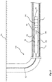
- a more detail view of a intervention system 100 is presented, i.e. the cable 10 and the connected downhole tool 50.
- the downhole tool 50 is suspended inside a casing 3, which forms the tubular structure for supporting the wellbore 1.
- the shown tool 50 has an active part 52, means 54 for controlling the active part 52, one or more sensors 56, and means 58 for advancing the entire tool 50.
- the active part 52 may e.g. be a cutter, a drill bit, a power suction tool, or other active parts being suitable to perform an operation downhole.
- Means 54 for controlling the active part 52 may consequently comprise rotation means for rotating the drill bit or a cutting head, or a pump for circulation fluid in the power suction tool.
- the one or more sensors 56 are configured to sense and to transmit detected physical properties like vibrations, temperature, etc. during operation of the wireline tool 50.
- the sensors 56 are arranged inside the wireline tool 50.
- the means 58 for advancing the active part 52 is a downhole tractor providing a forward motion by means of multiple driving wheels 59 extending towards the side of the casing 3.
- the downhole tractor 58 also functions as a centralizer.
- the wheels 59 may be driven by a hydraulic system and provide the necessary traction to move the active part 52 downhole.
- the means 58 for advancing the active part 52 may in other embodiments be a piston arrangement, such as a hydraulic piston.
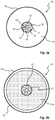
- a cable 10 for use with an intervention system 100, is shown in cross-section.
- the cable 10 has an inner tube 11, which forms a hollow cavity.
- the inner tube 11 is preferably cylindrical, i.e. the cross-section is circular.
- the inner tube 11 is made of a robust material, such as stainless steel or similar and dimensioned to enclose, and guide, a plurality of wires or cables 12.
- the wires are represented as seven electrical conductors 12; however, in some embodiments one or more of the electrical conductors 12 may be omitted, or replaced by other wire-like components such as optic fibers, etc.
- the inner tube 11 is surrounded by an outer tube 13.
- the outer tube 13 is arranged coaxially immediately outside the inner tube 11.
- the outer tube 13 is made of a composite material, e.g. a material comprising carbon fiber arranged in a polymer matrix.
- the amount of carbon in said material may preferably exceed 50%, such that the outer tube 13 will be electrically conducting, for reasons explained below.
- the cable 10 may further have an insulating cover 15 arranged on the external side of the outer tube 13.
- the insulating cover 15 may be a resin cover or similar, being capable of withstanding the harsh conditions downhole.
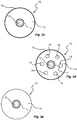
- Fig. 3b another embodiment of a cable 10 is shown. Similar to the embodiment of Fig. 3a , the cable 10 has the inner tube 11 housing the wires 12. The cable 10 also comprises the outer tube 13, which in this embodiment is made much thinner. Instead, a filler material 14 is arranged radially outwards of the inner tube 11, and radially inwards of the outer tube 13, for fixating the inner tube 11 inside the outer tube 13.
- the filler material may be any suitable material, having the purpose of affecting the density of the cable 10 and for supporting the inner tube 11 inside the outer tube 13.
- the cable may also be provided with an external insulating layer 15.
- Fig. 3c another embodiment of a cable 10 is shown.
- the cable 10 is similar to the cable shown in Fig. 3a , but in this embodiment there is only one electrical conductor 12 arranged within the inner tube 11.
- Fig. 3d is showing another example of a cable 10.
- one or more optical fibers 16 are provided.
- a plurality of optical fibers 16 are distributed in a spaced-apart manner within the outer tube 13, but it would also be possible to arrange the one or more optical fibers 16 in a filler material 14 (see Fig. 3b ) or within the inner tube 11.
- the one or more optical fibers 16 may preferably be used to provide measurements, such as temperature and/or pressure measurements.
- a yet further embodiment of a cable 10 is shown.
- the cable 10 is identical to the cable of Fig. 3c , except that the outer insulating layer 15 has been removed.
- Feeding power to and communicating with down-hole equipment is extremely important. Reliable connections that can withstand the harsh environmental conditions downhole are necessary. An electrical interface to be used downhole should consequently provide at least these features. Further to this, the electrical interface should be as efficient as possible in that it should not be too heavy, too expensive or too thick.
- a typical solution of solving downhole communication is by using shielded conduits or conductors where one conductor may be used for data communication and one for power transfer. Individual or common conductors may be used for return signals.
- the common conductor is beneficial since it reduces the number of conductors needed but there are drawbacks.
- a coaxial cable typically offers more than fifty times the bandwidth available in e.g. a twisted pair cable used for domestic internet access.
- the coaxial cable although bandwidth wise superior to pairwise communication, is a more complex cable and consequently adds cost and weight to a system.
- the shield used in coaxial cables is typically thin and not suitable to transfer high currents.
- the outer tube 13 comprising a composite material will allow it to act as return path for a signal provided through one or more of the electrical conduits 12.
- the conductivity and current handling of carbon fibers is comparable to that of copper which means that the outer tube 13 will provide a suitable return path for signals and current.
- the cable 10 may be used to supply power and/or a communication interface to a downhole tool 50 without substantially increasing the number of conductors 12 of the cable.
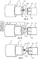
- Fig. 4a shows a schematic connection of one embodiment of a intervention system 100 wherein one conduit 12a is used to supply power to a power unit 541 of the downhole tool 50.
- the downhole tool 50 further comprises a signaling unit 542 but both the power unit 541 and signaling unit 542 are merely illustrating examples and the skilled person will, after reading this disclosure, understand that these units may or may not exist and may be distributed inside the downhole tool 50 or in separate independent or dependent units.
- a connection 401a-b between the cable 10 and the downhole tool 50 may be realized in numerous ways and in no way limiting examples may be e.g. mechanical connectors, soldering, welding or crimping.
- a second conduit 12a may be used or the downhole tool 50 may use its exterior to contact a casing.
- Fig. 4b shows one embodiment of the intervention system 100 wherein a single electric conductor 12a is connected to the downhole tool 50 via a connection 401a, and the outer tube 13 is connected to the downhole tool 50 via a connection 401b.
- the outer tube 13 is made of a conductive material e.g. a composite material or even a composite material comprising carbon fiber arranged in a polymer matrix, the outer tube 13 may provide a return path for the current.
- a reliable return path for the supply current is provided and the arrangement of the conductor 12a in relation to the outer tube 13 will have properties similar to those of a coaxial cable offering higher bandwidths compared to embodiments where the conductors are used for the return current. Further to this, one conductor 12a is made available for other uses or is even possible to remove. Either way, a more cost efficient, weight efficient and material efficient cable 10 is achieved since the number of conductors needed is reduced.
- the example of the intervention system shown in Fig. 4b may further be provided with a power source 202, such as a direct current source for providing electrical power to the downhole tool 50 via the one conductor 12a and the connection 401a.
- a data signal generator 206 is provided and configured to transmit a data signal, via a modulator 204, to the downhole tool 50 also via the single conductor 12a and the connection 401a.
- the shown example thereby describes an embodiment using only one conductor 12a and one return path 401b, 13.
- the conductor 12a will transfer DC power to the downhole tool 50, as well as data being AC coupled (or modulated) onto the DC voltage on the conductor 12a. It is possible to establish the communication in one-way or in two-way, half-duplex. Both techniques can be designed for the least number of conductors possible (only one conductor 12a for power/data to the downhole tool and one return conductor).
- the return current can be coupled to the cable armor, i.e. the outer tube 13, thus forming the return conductor.
- the return conductor can not only be the composite material of the outer tube 13; it is also possible to allow the return current to be coupled to steel, wellbore casing, wellbore fluids, etc., or a combination of them all.
- Fig. 4b is thereby showing an embodiment where a single center conductor 12a is used for both power/data and the outer tube 13 is the return for both as well.
- Fig. 4c another embodiment is presented wherein one of the conductors 12a is used to provide power to the power unit 541 of the downhole tool 50 and other conductors 12a are connected to the signaling unit 542; these may be used as a signaling interface suitable for e.g. communicating and controlling the downhole tool 50 and any sensors 56 or other equipment comprised in the downhole tool 50.
- the outer tube 13 may very well be used for supplying current to the downhole tool 50 and one of the conductors may provide the path for the return current.
- the outer tube 13 is used as a common reference when interfacing the downhole tool 50. Typically this would imply a ground potential.
- the intervention system 100 comprises a cable 10 and a downhole tool 50.
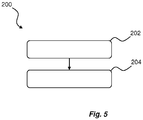
- the method 200 comprises a first step 202 of connecting the downhole tool 50 to one end of the cable 10, and a further step 204 of operating the downhole tool 50 such that it pulls the cable 10 further down the wellbore.
- the step 202 of connecting the downhole tool 50 to the cable 10 does not only include establishing a mechanical connection, but also connecting the downhole tool 50 electrically to the cable 10. Preferably, this is done in accordance with the description relating to Figs. 4a-c above.
- a stroking tool is a tool providing an axial force.
- the stroking tool comprises an electrical motor for driving a pump.
- the pump pumps fluid into a piston housing to move a piston acting therein.
- the piston is arranged on the stroker shaft.
- the pump may pump fluid into the piston housing on one side and simultaneously suck fluid out on the other side of the piston.
- a casing or well tubular metal structure is meant any kind of pipe, tubing, tubular, liner, string etc. used downhole in relation to oil or natural gas production.
- fluid or well fluid any kind of fluid that may be present in oil or gas wells downhole, such as natural gas, oil, oil mud, crude oil, water, etc.
- gas is meant any kind of gas composition present in a well, completion, or open hole
- oil is meant any kind of oil composition, such as crude oil, an oil-containing fluid, etc.
- Gas, oil, and water fluids may thus all comprise other elements or substances than gas, oil, and/or water, respectively.
- a downhole driving unit such as a downhole tractor can be used to push the tool all the way into position in the well.
- the downhole tractor may have projectable arms having wheels, wherein the wheels contact the inner surface of the casing for propelling the tractor and the tool forward in the casing.
- a downhole tractor is any kind of driving tool capable of pushing or pulling tools in a well downhole, such as a Well Tractor®.
Landscapes
- Engineering & Computer Science (AREA)
- Geology (AREA)
- Life Sciences & Earth Sciences (AREA)
- Mining & Mineral Resources (AREA)
- Physics & Mathematics (AREA)
- Geochemistry & Mineralogy (AREA)
- Fluid Mechanics (AREA)
- General Life Sciences & Earth Sciences (AREA)
- Environmental & Geological Engineering (AREA)
- Mechanical Engineering (AREA)
- Remote Sensing (AREA)
- Geophysics (AREA)
- Electromagnetism (AREA)
- Laying Of Electric Cables Or Lines Outside (AREA)
- Insulated Conductors (AREA)
- Cable Accessories (AREA)
- Communication Cables (AREA)
Priority Applications (9)
| Application Number | Priority Date | Filing Date | Title |
|---|---|---|---|
| EP18200224.6A EP3636874A1 (fr) | 2018-10-12 | 2018-10-12 | Système d'intervention et procédé de fonctionnement d'un système d'intervention |
| EP19783336.1A EP3864251B1 (fr) | 2018-10-12 | 2019-10-11 | Système d'intervention et procédé de fonctionnement d'un système d'intervention |
| BR112021005628-9A BR112021005628B1 (pt) | 2018-10-12 | 2019-10-11 | Sistema de intervenção e método para operar um sistema de intervenção |
| US16/599,348 US11414935B2 (en) | 2018-10-12 | 2019-10-11 | Intervention system and method for operating an intervention system |
| DK19783336.1T DK3864251T3 (da) | 2018-10-12 | 2019-10-11 | Interventionssystem og fremgangsmåde til betjening af et interventionssystem |
| PCT/EP2019/077556 WO2020074683A1 (fr) | 2018-10-12 | 2019-10-11 | Système d'intervention et procédé de fonctionnement d'un système d'intervention |
| CN201980065751.2A CN112823234A (zh) | 2018-10-12 | 2019-10-11 | 干预系统和用于操作干预系统的方法 |
| AU2019356964A AU2019356964B2 (en) | 2018-10-12 | 2019-10-11 | Intervention system and method for operating an intervention system |
| SA521421618A SA521421618B1 (ar) | 2018-10-12 | 2021-03-30 | نظام تدخل وطريقة لتشغيل نظام تدخل |
Applications Claiming Priority (1)
| Application Number | Priority Date | Filing Date | Title |
|---|---|---|---|
| EP18200224.6A EP3636874A1 (fr) | 2018-10-12 | 2018-10-12 | Système d'intervention et procédé de fonctionnement d'un système d'intervention |
Publications (1)
| Publication Number | Publication Date |
|---|---|
| EP3636874A1 true EP3636874A1 (fr) | 2020-04-15 |
Family
ID=63857713
Family Applications (2)
| Application Number | Title | Priority Date | Filing Date |
|---|---|---|---|
| EP18200224.6A Withdrawn EP3636874A1 (fr) | 2018-10-12 | 2018-10-12 | Système d'intervention et procédé de fonctionnement d'un système d'intervention |
| EP19783336.1A Active EP3864251B1 (fr) | 2018-10-12 | 2019-10-11 | Système d'intervention et procédé de fonctionnement d'un système d'intervention |
Family Applications After (1)
| Application Number | Title | Priority Date | Filing Date |
|---|---|---|---|
| EP19783336.1A Active EP3864251B1 (fr) | 2018-10-12 | 2019-10-11 | Système d'intervention et procédé de fonctionnement d'un système d'intervention |
Country Status (7)
| Country | Link |
|---|---|
| US (1) | US11414935B2 (fr) |
| EP (2) | EP3636874A1 (fr) |
| CN (1) | CN112823234A (fr) |
| AU (1) | AU2019356964B2 (fr) |
| DK (1) | DK3864251T3 (fr) |
| SA (1) | SA521421618B1 (fr) |
| WO (1) | WO2020074683A1 (fr) |
Families Citing this family (1)
| Publication number | Priority date | Publication date | Assignee | Title |
|---|---|---|---|---|
| WO2025144402A1 (fr) * | 2023-12-28 | 2025-07-03 | Halliburton Energy Services, Inc. | Encapsulation à faible résistance d'un conducteur encapsulé dans un tube pour l'alimentation d'un équipement dans des opérations de puits de forage |
Citations (6)
| Publication number | Priority date | Publication date | Assignee | Title |
|---|---|---|---|---|
| US20040244982A1 (en) * | 2002-08-15 | 2004-12-09 | Chitwood James E. | Substantially neutrally buoyant and positively buoyant electrically heated flowlines for production of subsea hydrocarbons |
| WO2011037974A2 (fr) * | 2009-09-22 | 2011-03-31 | Schlumberger Canada Limited | Câble métallique destiné à l'utilisation avec des ensembles tracteurs de forage |
| WO2015038150A1 (fr) * | 2013-09-13 | 2015-03-19 | Schlumberger Canada Limited | Câble lisse de fibre optique électroconducteur destiné à des opérations de tubage spiralé |
| WO2015095954A1 (fr) * | 2013-12-28 | 2015-07-02 | Trican Well Service, Ltd. | Système pour fabriquer un tube spiralé, dont le câble encapsulé en tube est incorporé dans le tube spiralé |
| EP3057106A1 (fr) * | 2015-02-10 | 2016-08-17 | Nexans | Câble pour le déploiement d'un tracteur de fond de trou |
| US20180023352A1 (en) * | 2013-12-28 | 2018-01-25 | Trican Well Service, Ltd. | Carbon fiber based tubing encapsulated cable |
Family Cites Families (5)
| Publication number | Priority date | Publication date | Assignee | Title |
|---|---|---|---|---|
| US8413723B2 (en) * | 2006-01-12 | 2013-04-09 | Schlumberger Technology Corporation | Methods of using enhanced wellbore electrical cables |
| BRPI0607373A2 (pt) * | 2005-01-25 | 2009-09-01 | Sabeus Inc | sistema e método aperfeiçoados para desdobrar uma fibra óptica em um poço |
| US7496258B1 (en) | 2007-11-09 | 2009-02-24 | Schlumberger Technology Corporation | Hydrocarbon monitoring cable |
| WO2014062061A1 (fr) | 2012-10-18 | 2014-04-24 | C6 Technologies As | Câble électrique pour intervention dans un puits pétrolier à tige composite en fibres |
| WO2015188083A1 (fr) * | 2014-06-05 | 2015-12-10 | Weatherford Technology Holdings, Llc | Câble de transport de fond de trou ayant un fil de support de charge conducteur et non métallique |
-
2018
- 2018-10-12 EP EP18200224.6A patent/EP3636874A1/fr not_active Withdrawn
-
2019
- 2019-10-11 EP EP19783336.1A patent/EP3864251B1/fr active Active
- 2019-10-11 CN CN201980065751.2A patent/CN112823234A/zh active Pending
- 2019-10-11 AU AU2019356964A patent/AU2019356964B2/en active Active
- 2019-10-11 WO PCT/EP2019/077556 patent/WO2020074683A1/fr not_active Ceased
- 2019-10-11 DK DK19783336.1T patent/DK3864251T3/da active
- 2019-10-11 US US16/599,348 patent/US11414935B2/en active Active
-
2021
- 2021-03-30 SA SA521421618A patent/SA521421618B1/ar unknown
Patent Citations (6)
| Publication number | Priority date | Publication date | Assignee | Title |
|---|---|---|---|---|
| US20040244982A1 (en) * | 2002-08-15 | 2004-12-09 | Chitwood James E. | Substantially neutrally buoyant and positively buoyant electrically heated flowlines for production of subsea hydrocarbons |
| WO2011037974A2 (fr) * | 2009-09-22 | 2011-03-31 | Schlumberger Canada Limited | Câble métallique destiné à l'utilisation avec des ensembles tracteurs de forage |
| WO2015038150A1 (fr) * | 2013-09-13 | 2015-03-19 | Schlumberger Canada Limited | Câble lisse de fibre optique électroconducteur destiné à des opérations de tubage spiralé |
| WO2015095954A1 (fr) * | 2013-12-28 | 2015-07-02 | Trican Well Service, Ltd. | Système pour fabriquer un tube spiralé, dont le câble encapsulé en tube est incorporé dans le tube spiralé |
| US20180023352A1 (en) * | 2013-12-28 | 2018-01-25 | Trican Well Service, Ltd. | Carbon fiber based tubing encapsulated cable |
| EP3057106A1 (fr) * | 2015-02-10 | 2016-08-17 | Nexans | Câble pour le déploiement d'un tracteur de fond de trou |
Also Published As
| Publication number | Publication date |
|---|---|
| CN112823234A (zh) | 2021-05-18 |
| US11414935B2 (en) | 2022-08-16 |
| EP3864251A1 (fr) | 2021-08-18 |
| SA521421618B1 (ar) | 2024-05-02 |
| EP3864251B1 (fr) | 2024-02-21 |
| AU2019356964B2 (en) | 2022-12-08 |
| AU2019356964A1 (en) | 2021-05-27 |
| US20200115964A1 (en) | 2020-04-16 |
| BR112021005628A2 (pt) | 2021-06-22 |
| DK3864251T3 (da) | 2024-05-27 |
| WO2020074683A1 (fr) | 2020-04-16 |
Similar Documents
| Publication | Publication Date | Title |
|---|---|---|
| US4051456A (en) | Apparatus for establishing and maintaining electric continuity in drill pipe | |
| US7493962B2 (en) | Control line telemetry | |
| EP2917481B1 (fr) | Appareil de télémétrie électromagnétique de fond de puits | |
| US5131464A (en) | Releasable electrical wet connect for a drill string | |
| EP3563032B1 (fr) | Dispositif de récupération d'énergie en fond de trou | |
| CN110382815A (zh) | 井下能量收集 | |
| CN102742084B (zh) | 用于连接电缆和井下工具的连接头以及相关联的介入装置 | |
| CN110382817A (zh) | 井下能量收集 | |
| CN110382816A (zh) | 井下通信 | |
| CA2963501C (fr) | Communications a bande interdite a travers un outil de puits presentant un exterieur modifie | |
| EP3864251B1 (fr) | Système d'intervention et procédé de fonctionnement d'un système d'intervention | |
| EP4086428B1 (fr) | Dispositif de récupération d'énergie en fond de trou | |
| RU2805143C2 (ru) | Система для внутрискважинных работ и способ эксплуатации системы для внутрискважинных работ | |
| NO20190236A1 (en) | Copper taped cable | |
| EP1696101B1 (fr) | Système et procédé adapté à être utilisé pour le netoyage du puits pendant le forage | |
| BR112021005628B1 (pt) | Sistema de intervenção e método para operar um sistema de intervenção | |
| US11085261B2 (en) | Well logging assembly | |
| CN116096980A (zh) | 启用连续油管的双遥测系统 | |
| GB2589815A (en) | Telemetry safety & life of well monitoring system | |
| GB2592173A (en) | Copper taped cable |
Legal Events
| Date | Code | Title | Description |
|---|---|---|---|
| PUAI | Public reference made under article 153(3) epc to a published international application that has entered the european phase |
Free format text: ORIGINAL CODE: 0009012 |
|
| STAA | Information on the status of an ep patent application or granted ep patent |
Free format text: STATUS: THE APPLICATION HAS BEEN PUBLISHED |
|
| AK | Designated contracting states |
Kind code of ref document: A1 Designated state(s): AL AT BE BG CH CY CZ DE DK EE ES FI FR GB GR HR HU IE IS IT LI LT LU LV MC MK MT NL NO PL PT RO RS SE SI SK SM TR |
|
| AX | Request for extension of the european patent |
Extension state: BA ME |
|
| STAA | Information on the status of an ep patent application or granted ep patent |
Free format text: STATUS: THE APPLICATION IS DEEMED TO BE WITHDRAWN |
|
| 18D | Application deemed to be withdrawn |
Effective date: 20201016 |