EP3636896B1 - Steuergeräteanordnung - Google Patents
Steuergeräteanordnung Download PDFInfo
- Publication number
- EP3636896B1 EP3636896B1 EP19196630.8A EP19196630A EP3636896B1 EP 3636896 B1 EP3636896 B1 EP 3636896B1 EP 19196630 A EP19196630 A EP 19196630A EP 3636896 B1 EP3636896 B1 EP 3636896B1
- Authority
- EP
- European Patent Office
- Prior art keywords
- valve
- assembly
- switch
- flow passage
- open
- Prior art date
- Legal status (The legal status is an assumption and is not a legal conclusion. Google has not performed a legal analysis and makes no representation as to the accuracy of the status listed.)
- Active
Links
Images


Classifications
-
- F—MECHANICAL ENGINEERING; LIGHTING; HEATING; WEAPONS; BLASTING
- F02—COMBUSTION ENGINES; HOT-GAS OR COMBUSTION-PRODUCT ENGINE PLANTS
- F02C—GAS-TURBINE PLANTS; AIR INTAKES FOR JET-PROPULSION PLANTS; CONTROLLING FUEL SUPPLY IN AIR-BREATHING JET-PROPULSION PLANTS
- F02C9/00—Controlling gas-turbine plants; Controlling fuel supply in air- breathing jet-propulsion plants
- F02C9/16—Control of working fluid flow
- F02C9/18—Control of working fluid flow by bleeding, bypassing or acting on variable working fluid interconnections between turbines or compressors or their stages
-
- F—MECHANICAL ENGINEERING; LIGHTING; HEATING; WEAPONS; BLASTING
- F02—COMBUSTION ENGINES; HOT-GAS OR COMBUSTION-PRODUCT ENGINE PLANTS
- F02C—GAS-TURBINE PLANTS; AIR INTAKES FOR JET-PROPULSION PLANTS; CONTROLLING FUEL SUPPLY IN AIR-BREATHING JET-PROPULSION PLANTS
- F02C6/00—Plural gas-turbine plants; Combinations of gas-turbine plants with other apparatus; Adaptations of gas-turbine plants for special use
- F02C6/04—Gas-turbine plants providing heated or pressurised working fluid for other apparatus, e.g. without mechanical power output
- F02C6/06—Gas-turbine plants providing heated or pressurised working fluid for other apparatus, e.g. without mechanical power output providing compressed gas
- F02C6/08—Gas-turbine plants providing heated or pressurised working fluid for other apparatus, e.g. without mechanical power output providing compressed gas the gas being bled from the gas-turbine compressor
-
- F—MECHANICAL ENGINEERING; LIGHTING; HEATING; WEAPONS; BLASTING
- F02—COMBUSTION ENGINES; HOT-GAS OR COMBUSTION-PRODUCT ENGINE PLANTS
- F02M—SUPPLYING COMBUSTION ENGINES IN GENERAL WITH COMBUSTIBLE MIXTURES OR CONSTITUENTS THEREOF
- F02M53/00—Fuel-injection apparatus characterised by having heating, cooling or thermally-insulating means
- F02M53/04—Injectors with heating, cooling, or thermally-insulating means
- F02M53/08—Injectors with heating, cooling, or thermally-insulating means with air cooling
-
- F—MECHANICAL ENGINEERING; LIGHTING; HEATING; WEAPONS; BLASTING
- F16—ENGINEERING ELEMENTS AND UNITS; GENERAL MEASURES FOR PRODUCING AND MAINTAINING EFFECTIVE FUNCTIONING OF MACHINES OR INSTALLATIONS; THERMAL INSULATION IN GENERAL
- F16K—VALVES; TAPS; COCKS; ACTUATING-FLOATS; DEVICES FOR VENTING OR AERATING
- F16K11/00—Multiple-way valves, e.g. mixing valves; Pipe fittings incorporating such valves
- F16K11/02—Multiple-way valves, e.g. mixing valves; Pipe fittings incorporating such valves with all movable sealing faces moving as one unit
- F16K11/04—Multiple-way valves, e.g. mixing valves; Pipe fittings incorporating such valves with all movable sealing faces moving as one unit comprising only lift valves
- F16K11/044—Multiple-way valves, e.g. mixing valves; Pipe fittings incorporating such valves with all movable sealing faces moving as one unit comprising only lift valves with movable valve members positioned between valve seats
-
- F—MECHANICAL ENGINEERING; LIGHTING; HEATING; WEAPONS; BLASTING
- F16—ENGINEERING ELEMENTS AND UNITS; GENERAL MEASURES FOR PRODUCING AND MAINTAINING EFFECTIVE FUNCTIONING OF MACHINES OR INSTALLATIONS; THERMAL INSULATION IN GENERAL
- F16K—VALVES; TAPS; COCKS; ACTUATING-FLOATS; DEVICES FOR VENTING OR AERATING
- F16K11/00—Multiple-way valves, e.g. mixing valves; Pipe fittings incorporating such valves
- F16K11/02—Multiple-way valves, e.g. mixing valves; Pipe fittings incorporating such valves with all movable sealing faces moving as one unit
- F16K11/04—Multiple-way valves, e.g. mixing valves; Pipe fittings incorporating such valves with all movable sealing faces moving as one unit comprising only lift valves
- F16K11/048—Multiple-way valves, e.g. mixing valves; Pipe fittings incorporating such valves with all movable sealing faces moving as one unit comprising only lift valves with valve seats positioned between movable valve members
-
- F—MECHANICAL ENGINEERING; LIGHTING; HEATING; WEAPONS; BLASTING
- F16—ENGINEERING ELEMENTS AND UNITS; GENERAL MEASURES FOR PRODUCING AND MAINTAINING EFFECTIVE FUNCTIONING OF MACHINES OR INSTALLATIONS; THERMAL INSULATION IN GENERAL
- F16K—VALVES; TAPS; COCKS; ACTUATING-FLOATS; DEVICES FOR VENTING OR AERATING
- F16K31/00—Actuating devices; Operating means; Releasing devices
- F16K31/02—Actuating devices; Operating means; Releasing devices electric; magnetic
- F16K31/04—Actuating devices; Operating means; Releasing devices electric; magnetic using a motor
- F16K31/046—Actuating devices; Operating means; Releasing devices electric; magnetic using a motor with electric means, e.g. electric switches, to control the motor or to control a clutch between the valve and the motor
-
- F—MECHANICAL ENGINEERING; LIGHTING; HEATING; WEAPONS; BLASTING
- F16—ENGINEERING ELEMENTS AND UNITS; GENERAL MEASURES FOR PRODUCING AND MAINTAINING EFFECTIVE FUNCTIONING OF MACHINES OR INSTALLATIONS; THERMAL INSULATION IN GENERAL
- F16K—VALVES; TAPS; COCKS; ACTUATING-FLOATS; DEVICES FOR VENTING OR AERATING
- F16K31/00—Actuating devices; Operating means; Releasing devices
- F16K31/02—Actuating devices; Operating means; Releasing devices electric; magnetic
- F16K31/06—Actuating devices; Operating means; Releasing devices electric; magnetic using a magnet, e.g. diaphragm valves, cutting off by means of a liquid
- F16K31/0603—Multiple-way valves
- F16K31/0624—Lift valves
- F16K31/0627—Lift valves with movable valve member positioned between seats
- F16K31/0631—Lift valves with movable valve member positioned between seats with ball shaped valve members
-
- F—MECHANICAL ENGINEERING; LIGHTING; HEATING; WEAPONS; BLASTING
- F16—ENGINEERING ELEMENTS AND UNITS; GENERAL MEASURES FOR PRODUCING AND MAINTAINING EFFECTIVE FUNCTIONING OF MACHINES OR INSTALLATIONS; THERMAL INSULATION IN GENERAL
- F16K—VALVES; TAPS; COCKS; ACTUATING-FLOATS; DEVICES FOR VENTING OR AERATING
- F16K31/00—Actuating devices; Operating means; Releasing devices
- F16K31/02—Actuating devices; Operating means; Releasing devices electric; magnetic
- F16K31/06—Actuating devices; Operating means; Releasing devices electric; magnetic using a magnet, e.g. diaphragm valves, cutting off by means of a liquid
- F16K31/0603—Multiple-way valves
- F16K31/0624—Lift valves
- F16K31/0634—Lift valves with fixed seats positioned between movable valve members
- F16K31/0637—Lift valves with fixed seats positioned between movable valve members with ball shaped valve members
-
- F—MECHANICAL ENGINEERING; LIGHTING; HEATING; WEAPONS; BLASTING
- F16—ENGINEERING ELEMENTS AND UNITS; GENERAL MEASURES FOR PRODUCING AND MAINTAINING EFFECTIVE FUNCTIONING OF MACHINES OR INSTALLATIONS; THERMAL INSULATION IN GENERAL
- F16K—VALVES; TAPS; COCKS; ACTUATING-FLOATS; DEVICES FOR VENTING OR AERATING
- F16K31/00—Actuating devices; Operating means; Releasing devices
- F16K31/12—Actuating devices; Operating means; Releasing devices actuated by fluid
- F16K31/122—Actuating devices; Operating means; Releasing devices actuated by fluid the fluid acting on a piston
- F16K31/1221—Actuating devices; Operating means; Releasing devices actuated by fluid the fluid acting on a piston one side of the piston being spring-loaded
-
- F—MECHANICAL ENGINEERING; LIGHTING; HEATING; WEAPONS; BLASTING
- F16—ENGINEERING ELEMENTS AND UNITS; GENERAL MEASURES FOR PRODUCING AND MAINTAINING EFFECTIVE FUNCTIONING OF MACHINES OR INSTALLATIONS; THERMAL INSULATION IN GENERAL
- F16K—VALVES; TAPS; COCKS; ACTUATING-FLOATS; DEVICES FOR VENTING OR AERATING
- F16K31/00—Actuating devices; Operating means; Releasing devices
- F16K31/12—Actuating devices; Operating means; Releasing devices actuated by fluid
- F16K31/122—Actuating devices; Operating means; Releasing devices actuated by fluid the fluid acting on a piston
- F16K31/1226—Actuating devices; Operating means; Releasing devices actuated by fluid the fluid acting on a piston the fluid circulating through the piston
-
- F—MECHANICAL ENGINEERING; LIGHTING; HEATING; WEAPONS; BLASTING
- F16—ENGINEERING ELEMENTS AND UNITS; GENERAL MEASURES FOR PRODUCING AND MAINTAINING EFFECTIVE FUNCTIONING OF MACHINES OR INSTALLATIONS; THERMAL INSULATION IN GENERAL
- F16K—VALVES; TAPS; COCKS; ACTUATING-FLOATS; DEVICES FOR VENTING OR AERATING
- F16K31/00—Actuating devices; Operating means; Releasing devices
- F16K31/12—Actuating devices; Operating means; Releasing devices actuated by fluid
- F16K31/42—Actuating devices; Operating means; Releasing devices actuated by fluid by means of electrically-actuated members in the supply or discharge conduits of the fluid motor
-
- F—MECHANICAL ENGINEERING; LIGHTING; HEATING; WEAPONS; BLASTING
- F16—ENGINEERING ELEMENTS AND UNITS; GENERAL MEASURES FOR PRODUCING AND MAINTAINING EFFECTIVE FUNCTIONING OF MACHINES OR INSTALLATIONS; THERMAL INSULATION IN GENERAL
- F16K—VALVES; TAPS; COCKS; ACTUATING-FLOATS; DEVICES FOR VENTING OR AERATING
- F16K49/00—Means in or on valves for heating or cooling
- F16K49/005—Circulation means for a separate heat transfer fluid
-
- F—MECHANICAL ENGINEERING; LIGHTING; HEATING; WEAPONS; BLASTING
- F05—INDEXING SCHEMES RELATING TO ENGINES OR PUMPS IN VARIOUS SUBCLASSES OF CLASSES F01-F04
- F05D—INDEXING SCHEME FOR ASPECTS RELATING TO NON-POSITIVE-DISPLACEMENT MACHINES OR ENGINES, GAS-TURBINES OR JET-PROPULSION PLANTS
- F05D2260/00—Function
- F05D2260/20—Heat transfer, e.g. cooling
-
- Y—GENERAL TAGGING OF NEW TECHNOLOGICAL DEVELOPMENTS; GENERAL TAGGING OF CROSS-SECTIONAL TECHNOLOGIES SPANNING OVER SEVERAL SECTIONS OF THE IPC; TECHNICAL SUBJECTS COVERED BY FORMER USPC CROSS-REFERENCE ART COLLECTIONS [XRACs] AND DIGESTS
- Y02—TECHNOLOGIES OR APPLICATIONS FOR MITIGATION OR ADAPTATION AGAINST CLIMATE CHANGE
- Y02T—CLIMATE CHANGE MITIGATION TECHNOLOGIES RELATED TO TRANSPORTATION
- Y02T50/00—Aeronautics or air transport
- Y02T50/60—Efficient propulsion technologies, e.g. for aircraft
Definitions
- the present invention relates to an assembly comprising a valve and a controller assembly for use in a gas turbine engine, for example a gas turbine aircraft engine, and a gas turbine engine that includes that assembly.
- controllers e.g. that control whether a system is in a first state (e.g. ON) or a second state (e.g. OFF) or that control the position of another component, may need to withstand and function in high temperature and pressure environments.
- a first state e.g. ON
- a second state e.g. OFF
- controllers for use in gas turbine aircraft engines will need to be able to function in this environment.
- United Kingdom patent application GB 1125102 A discloses a solenoid actuator and a solenoid actuated fluid control valve.
- the solenoid actuator has a magnetic circuit including a magnetic element connected therein by two non-magnetic gaps.
- the magnetic element is mounted in relation to the remainder of the magnetic circuit in order to be capable of movement along a path at least one end of which is determined by a stop position, and is maintained in the stop position, when not actuated, by a biasing force.
- the solenoid actuator also has means, responsive to electric current, for producing in the magnetic circuit a magnetic flux whose magnitude is related to the current.
- Parts of the magnetic element and parts of the remainder of the magnetic circuit adjacent the respective gaps are proportioned and arranged so that the magnetic element moves in use from the stop position, the reluctance of one gap changes by at most a relatively small amount, while that of the other gap changes in reverse sense by a relatively large amount, the element being displaced against the biasing force through a distance which is continuously dependent on the magnitude of the current.
- United States patent US 6116570 A relates to an electromagnetic actuator 10 including an upper electromagnet, a lower electromagnet 14 spaced from the upper electromagnet and an armature mounted for movement between the upper and lower electromagnets.
- Shaft structure is operatively associated with the armature for movement therewith.
- a gas exchange valve is operated by the armature.
- At least one bushing 24 supports the shaft structure.
- a metring valve and port structure are provided in the actuator and are constructed and arranged to communicate hydraulic fluid from a source thereof with the at least one bushing and with the armature to cool the armature.
- the metering valve is preferably associated with a hydraulic lash adjuster which is constructed and arranged to provide hydraulic fluid to the lash adjuster only when the gas exchange valve is in a closed position.
- European patent application EP 3246606 A1 relates to a solenoid for a bleed valve including a solenoid body with an actuation fluid passage, a bleed valve passage, and a drive fluid chamber.
- a main armature is disposed within the solenoid body and is movable between open and closed positions, the actuation fluid passage being in fluid communication with the control outlet in the open position, the actuation fluid passage being fluidly isolated from the bleed valve passage in the second position.
- a pilot armature is disposed within the solenoid body, is movable relative to the main armature, and is operably coupled to the main armature by the drive fluid chamber to move the main armature between the open and closed positions by controlling issue of a drive fluid into and out of the drive fluid chamber.
- the present invention provides an assembly and a gas turbine engine as set out in the appended claims.
- a controller assembly comprising a valve, an electromechanical actuator and a single-stage pneumatic flow switch.
- the switch is configured to thermally protect the electromechanical actuator by a supply of cooling fluid.
- the controller assembly disclosed herein is able to support the continual flow of hotter air (e.g. bleed air) than its thermal capability if it was uncooled.
- the controller assembly may be disposed in a flow passage for hot air (e.g. hot bleed air), but when the switch is configured to thermally protect the actuator, the actuator is surrounded by a cooling jacket of the cooling air. This allows the actuator to operate beyond its thermal design point as it is thermally shielded by the cooling jacket from the hot air.
- the switch is configured to thermally protect the controller assembly by a supply of cooling fluid.
- the single-stage pneumatic flow switch is movable between a first mode in which the switch is configured to open a cooling fluid flow passage and a second mode in which the switch is configured to close the cooling fluid flow passage.
- the cooling fluid flow passage may be connected to a supply of cooling fluid. Therefore the switch is able to switch to a cooling flow that washes over the actuator when it is energised or de-energised (depending on the configuration), and thereby provide a cooling jacket around thermally sensitive components of the actuator.
- the electromechanical actuator is coupled to the valve, which is movable between an open and a closed configuration.
- the electromechanical actuator is disposed in a fluid flow outlet of the valve. As hot air may flow through the valve, the actuator may therefore be disposed in a flow of hot air when the valve is open.
- the actuator may comprise a solenoid which may be connected to the valve to actuate the valve (e.g. via electrical wiring). Any type of solenoid may be used, for example, an oil, gas, hydraulic or pneumatic solenoid.
- the single-stage pneumatic flow switch When in the first mode, the single-stage pneumatic flow switch may be configured to open a further fluid flow passage and, when in the second mode, the switch may be configured to close the further fluid flow passage.
- the further fluid flow passage may be connected to a control chamber of the valve.
- the further flow passage may be to provide pressure to the valve control chamber and therefore may be connected to a source of pressure (e.g. pressurised fluid).
- the single-stage pneumatic flow switch may be configured to cause the valve to open and, when in the second mode, the switch may be configured to cause the valve to close.
- the single-stage pneumatic flow switch may be configured to open a vent flow passage so that the control chamber of the valve is in fluid communication with the vent flow passage to thereby vent the contents of the control chamber (e.g. pressurised fluid contained therein).
- the switch may be configured to supply pressure to the valve control chamber to open the valve, or to vent the control chamber to close the valve.
- the switch In the first mode the switch may be configured to open the further flow passage to supply pressure to the control chamber which will open the valve.
- the switch In the second mode, the switch may be configured to close the valve by opening the vent flow passage to vent the control chamber which will close the valve. In this way, the switch is configured to open the cooling flow passage when the valve is open, and close the cooling flow passage when the valve is closed.
- the electromechanical actuator may be configured to cause the switch to transition between its first and second modes, thereby configured to cause the valve to transition between an open and closed configuration.
- the electromechanical actuator may therefore be configured to open/close the valve and open/close the cooling flow passage etc.
- the switch comprises a primary and secondary flow switch, the primary flow switch being a 2-state 3-way switch (to selectively open or close a control chamber flow passage and a vent flow passage) and a 2-state 2-way switch (to selectively open or close a cooling fluid flow passage).
- the primary and secondary switches are disposed in tandem, in that movement of one causes movement of the other, e.g. they move concurrently.
- the primary and secondary switches are connected to one another. Therefore, when the primary and secondary flow switches are open, hot air may be flowing over the controller assembly and actuator, but the actuator is thermally isolated by the cooling air jacket which is flowing through the cooling flow passage.
- the further flow passage may be connected to a source of fluid at a higher pressure than the pressure across the valve to thereby pressurise the control chamber of the valve.
- the further flow passage may be connected to a source of fluid from an upstream side of the valve.
- a gas turbine engine for an aircraft, the gas turbine engine comprising an engine core comprising a turbine, a compressor, and a core shaft connecting the turbine to the compressor, a fan located upstream of the engine core, the fan comprising a plurality of fan blades, and an assembly as described above.
- the controller assembly may be disposed within a valve body, and at least one spoke may connect the valve body to the electromechanical actuator.
- the at least one spoke may comprise a radial spoke or an axial spoke (e.g. with respect to an axis of the valve, e.g. a longitudinal valve axis, e.g. an axis aligned with a flow direction through the valve).
- the cooling fluid flow passage may be at least partially located within one spoke.
- the controller assembly may be disposed within a/the valve body, which may comprise a valve having a control chamber. At least one spoke may connect the valve body to the electromechanical actuator. A pressure source may be connected to the valve control chamber, which may be at least partially located within one spoke.
- the controller assembly may be connected to the gas turbine engine such that bleed air is configured to flow through the valve assembly and around the actuator.
- the controller assembly may be connected to the compressor and/or the turbine of the gas turbine engine such that bleed air is configured to flow through the valve assembly and around the actuator.
- one fluid flow passage may be at least partially disposed within a spoke connecting the valve body to the actuator.
- one spoke may carry fluid, e.g. pressurised fluid, to the valve control chamber.
- One spoke may carry cooling fluid to the actuator.
- One spoke may carry a wire, e.g. an electrical conductor, from the actuator to the valve so that the actuator is configured to control the valve (e.g. configured to open/close the valve).
- the controller assembly and/or actuator may be disposed in the valve flow passage concentrically to the valve body, e.g. in an outlet of the valve in the valve efflux flow. In one example, the controller assembly and/or actuator may be disposed in the valve flow passage non-concentrically to the valve body, e.g. in an outlet of the valve in the valve efflux flow. In either example, the control chamber and/or the cooling flow passage may be outside, e.g. not within, any one of the spokes.
- the controller assembly and/or actuator may be disposed outside the valve flow passage, e.g. outside of the valve efflux flow.
- the cooling flow, after washing over the actuator, and the valve main flow may exhaust into the same sink pressure.
- the cooling flow, after washing over the actuator may directed (e.g. be piped) to a separate sink pressure which may be at a different pressure level.
- the assembly may comprise a first sink pressure and a second sink pressure and, in one example, the cooling flow after flowing around the actuator may be directed to the first sink pressure and the valve efflux flow may be directed to the second sink pressure. In another example they may be both directed to the same sink pressure.
- the cooling fluid flow passage may be connected to a source of cooling fluid.
- the control chamber flow passage may be connected to a source of pressure (e.g. "muscle air” or “servo pressure”).
- control assembly only provides cooling flow when the valve is open and the actuator is thereby in the presence of high temperature efflux air from the valve.
- hot air does not pass by the actuator and cooling flow does not pass around the actuator (as it is not necessary to cool the actuator when the actuator is not exposed to hot air).
- a specific fuel consumption penalty is only incurred when it is necessary to cool the controller, and wasteful parasitic cooling flows may therefore be avoided.
- the controller assembly may therefore enable the actuator within the assembly to be thermally protected when hot air passes through the assembly, allowing the actuator to continue to function to specification when the surrounding air is hotter than the thermal capability of the actuator.
- This configuration may also minimise parasitic cooling flow as cooling flow may be employed only when it is needed, and may also eliminate the need to use controller banks (which can be costly and inconvenient to replace) as the control assembly may be located within, or integral to, the valve itself. Furthermore, as the control assembly may be integral to the valve, a flow amplifier may not be needed with no compromise in response time. This, in turn, allows for cost, component complexity and weight to be reduced.
- the present invention may relate to a gas turbine engine.
- a gas turbine engine may comprise an engine core comprising a turbine, a combustor, a compressor, and a core shaft connecting the turbine to the compressor.
- a gas turbine engine may comprise a fan (having fan blades) located upstream of the engine core.
- the gas turbine engine may comprise a gearbox that receives an input from the core shaft and outputs drive to the fan so as to drive the fan at a lower rotational speed than the core shaft.
- the input to the gearbox may be directly from the core shaft, or indirectly from the core shaft, for example via a spur shaft and/or gear.
- the core shaft may rigidly connect the turbine and the compressor, such that the turbine and compressor rotate at the same speed (with the fan rotating at a lower speed).
- the gas turbine engine as described and/or claimed herein may have any suitable general architecture.
- the gas turbine engine may have any desired number of shafts that connect turbines and compressors, for example one, two or three shafts.
- the turbine connected to the core shaft may be a first turbine
- the compressor connected to the core shaft may be a first compressor
- the core shaft may be a first core shaft.
- the engine core may further comprise a second turbine, a second compressor, and a second core shaft connecting the second turbine to the second compressor.
- the second turbine, second compressor, and second core shaft may be arranged to rotate at a higher rotational speed than the first core shaft.
- the second compressor may be positioned axially downstream of the first compressor.
- the second compressor may be arranged to receive (for example directly receive, for example via a generally annular duct) flow from the first compressor.
- the gearbox may be arranged to be driven by the core shaft that is configured to rotate (for example in use) at the lowest rotational speed (for example the first core shaft in the example above).
- the gearbox may be arranged to be driven only by the core shaft that is configured to rotate (for example in use) at the lowest rotational speed (for example only be the first core shaft, and not the second core shaft, in the example above).
- the gearbox may be arranged to be driven by any one or more shafts, for example the first and/or second shafts in the example above.
- a combustor may be provided axially downstream of the fan and compressor(s).
- the combustor may be directly downstream of (for example at the exit of) the second compressor, where a second compressor is provided.
- the flow at the exit to the combustor may be provided to the inlet of the second turbine, where a second turbine is provided.
- the combustor may be provided upstream of the turbine(s).
- each compressor may comprise any number of stages, for example multiple stages.
- Each stage may comprise a row of rotor blades and a row of stator vanes, which may be variable stator vanes (in that their angle of incidence may be variable).
- the row of rotor blades and the row of stator vanes may be axially offset from each other.
- each turbine may comprise any number of stages, for example multiple stages.
- Each stage may comprise a row of rotor blades and a row of stator vanes.
- the row of rotor blades and the row of stator vanes may be axially offset from each other.
- Each fan blade may be defined as having a radial span extending from a root (or hub) at a radially inner gas-washed location, or 0% span position, to a tip at a 100% span position.
- the ratio of the radius of the fan blade at the hub to the radius of the fan blade at the tip may be less than (or on the order of) any of: 0.4, 0.39, 0.38 0.37, 0.36, 0.35, 0.34, 0.33, 0.32, 0.31, 0.3, 0.29, 0.28, 0.27, 0.26, or 0.25.
- the ratio of the radius of the fan blade at the hub to the radius of the fan blade at the tip may be in an inclusive range bounded by any two of the values in the previous sentence (i.e.
- the values may form upper or lower bounds). These ratios may commonly be referred to as the hub-to-tip ratio.
- the radius at the hub and the radius at the tip may both be measured at the leading edge (or axially forwardmost) part of the blade.
- the hub-to-tip ratio refers, of course, to the gas-washed portion of the fan blade, i.e. the portion radially outside any platform.
- the radius of the fan may be measured between the engine centreline and the tip of a fan blade at its leading edge.
- the fan diameter (which may simply be twice the radius of the fan) may be greater than (or on the order of) any of: 250 cm (around 100 inches), 260 cm, 270 cm (around 105 inches), 280 cm (around 110 inches), 290 cm (around 115 inches), 300 cm (around 120 inches), 310 cm, 320 cm (around 125 inches), 330 cm (around 130 inches), 340 cm (around 135 inches), 350cm, 360cm (around 140 inches), 370 cm (around 145 inches), 380 (around 150 inches) cm or 390 cm (around 155 inches).
- the fan diameter may be in an inclusive range bounded by any two of the values in the previous sentence (i.e. the values may form upper or lower bounds).
- the rotational speed of the fan may vary in use. Generally, the rotational speed is lower for fans with a higher diameter. Purely by way of non-limitative example, the rotational speed of the fan at cruise conditions may be less than 2500 rpm, for example less than 2300 rpm. Purely by way of further non-limitative example, the rotational speed of the fan at cruise conditions for an engine having a fan diameter in the range of from 250 cm to 300 cm (for example 250 cm to 280 cm) may be in the range of from 1700 rpm to 2500 rpm, for example in the range of from 1800 rpm to 2300 rpm, for example in the range of from 1900 rpm to 2100 rpm.
- the rotational speed of the fan at cruise conditions for an engine having a fan diameter in the range of from 320 cm to 380 cm may be in the range of from 1200 rpm to 2000 rpm, for example in the range of from 1300 rpm to 1800 rpm, for example in the range of from 1400 rpm to 1600 rpm.
- the fan In use of the gas turbine engine, the fan (with associated fan blades) rotates about a rotational axis. This rotation results in the tip of the fan blade moving with a velocity U tip .
- the work done by the fan blades 13 on the flow results in an enthalpy rise dH of the flow.
- a fan tip loading may be defined as dH/U tip 2 , where dH is the enthalpy rise (for example the 1-D average enthalpy rise) across the fan and U tip is the (translational) velocity of the fan tip, for example at the leading edge of the tip (which may be defined as fan tip radius at leading edge multiplied by angular speed).
- the fan tip loading at cruise conditions may be greater than (or on the order of) any of: 0.3, 0.31, 0.32, 0.33, 0.34, 0.35, 0.36, 0.37, 0.38, 0.39 or 0.4 (all units in this paragraph being Jkg -1 K -1 /(ms -1 ) 2 ).
- the fan tip loading may be in an inclusive range bounded by any two of the values in the previous sentence (i.e. the values may form upper or lower bounds).
- Gas turbine engines in accordance with the present invention may have any desired bypass ratio, where the bypass ratio is defined as the ratio of the mass flow rate of the flow through the bypass duct to the mass flow rate of the flow through the core at cruise conditions.
- the bypass ratio may be greater than (or on the order of) any of the following: 10, 10.5, 11, 11.5, 12, 12.5, 13, 13.5, 14, 14.5, 15, 15.5, 16, 16.5, or 17.
- the bypass ratio may be in an inclusive range bounded by any two of the values in the previous sentence (i.e. the values may form upper or lower bounds).
- the bypass duct may be substantially annular.
- the bypass duct may be radially outside the engine core.
- the radially outer surface of the bypass duct may be defined by a nacelle and/or a fan case.
- the overall pressure ratio of a gas turbine engine as described and/or claimed herein may be defined as the ratio of the stagnation pressure upstream of the fan to the stagnation pressure at the exit of the highest pressure compressor (before entry into the combustor).
- the overall pressure ratio of a gas turbine engine as described and/or claimed herein at cruise may be greater than (or on the order of) any of the following: 35, 40, 45, 50, 55, 60, 65, 70, 75.
- the overall pressure ratio may be in an inclusive range bounded by any two of the values in the previous sentence (i.e. the values may form upper or lower bounds).
- Specific thrust of an engine may be defined as the net thrust of the engine divided by the total mass flow through the engine. At cruise conditions, the specific thrust of an engine described and/or claimed herein may be less than (or on the order of) any of the following: 110 Nkg -1 s, 105 Nkg -1 s, 100 Nkg -1 s, 95 Nkg -1 s, 90 Nkg -1 s, 85 Nkg -1 s or 80 Nkg -1 s.
- the specific thrust may be in an inclusive range bounded by any two of the values in the previous sentence (i.e. the values may form upper or lower bounds). Such engines may be particularly efficient in comparison with conventional gas turbine engines.
- a gas turbine engine as described and/or claimed herein may have any desired maximum thrust.
- a gas turbine as described and/or claimed herein may be capable of producing a maximum thrust of at least (or on the order of) any of the following: 160kN, 170kN, 180kN, 190kN, 200kN, 250kN, 300kN, 350kN, 400kN, 450kN, 500kN, or 550kN.
- the maximum thrust may be in an inclusive range bounded by any two of the values in the previous sentence (i.e. the values may form upper or lower bounds).
- the thrust referred to above may be the maximum net thrust at standard atmospheric conditions at sea level plus 15 °C (ambient pressure 101.3 kPa, temperature 30 °C), with the engine static.
- the temperature of the flow at the entry to the high pressure turbine may be particularly high.
- This temperature which may be referred to as TET
- TET may be measured at the exit to the combustor, for example immediately upstream of the first turbine vane, which itself may be referred to as a nozzle guide vane.
- the TET may be at least (or on the order of) any of the following: 1400K, 1450K, 1500K, 1550K, 1600K or 1650K.
- the TET at cruise may be in an inclusive range bounded by any two of the values in the previous sentence (i.e. the values may form upper or lower bounds).
- the maximum TET in use of the engine may be, for example, at least (or on the order of) any of the following: 1700K, 1750K, 1800K, 1850K, 1900K, 1950K or 2000K.
- the maximum TET may be in an inclusive range bounded by any two of the values in the previous sentence (i.e. the values may form upper or lower bounds).
- the maximum TET may occur, for example, at a high thrust condition, for example at a maximum take-off (MTO) condition.
- MTO maximum take-off
- a fan blade and/or aerofoil portion of a fan blade described and/or claimed herein may be manufactured from any suitable material or combination of materials.
- at least a part of the fan blade and/or aerofoil may be manufactured at least in part from a composite, for example a metal matrix composite and/or an organic matrix composite, such as carbon fibre.
- at least a part of the fan blade and/or aerofoil may be manufactured at least in part from a metal, such as a titanium based metal or an aluminium based material (such as an aluminium-lithium alloy) or a steel based material.
- the fan blade may comprise at least two regions manufactured using different materials.
- the fan blade may have a protective leading edge, which may be manufactured using a material that is better able to resist impact (for example from birds, ice or other material) than the rest of the blade.
- a leading edge may, for example, be manufactured using titanium or a titanium-based alloy.
- the fan blade may have a carbon-fibre or aluminium based body (such as an aluminium lithium alloy) with a titanium leading edge.
- a fan as described and/or claimed herein may comprise a central portion, from which the fan blades may extend, for example in a radial direction.
- the fan blades may be attached to the central portion in any desired manner.
- each fan blade may comprise a fixture which may engage a corresponding slot in the hub (or disc).
- a fixture may be in the form of a dovetail that may slot into and/or engage a corresponding slot in the hub/disc in order to fix the fan blade to the hub/disc.
- the fan blades maybe formed integrally with a central portion.
- Such an arrangement may be referred to as a blisk or a bling. Any suitable method may be used to manufacture such a blisk or bling.
- at least a part of the fan blades may be machined from a block and/or at least part of the fan blades may be attached to the hub/disc by welding, such as linear friction welding.
- variable area nozzle may allow the exit area of the bypass duct to be varied in use.
- the general principles of the present invention may apply to engines with or without a VAN.
- the fan of a gas turbine as described and/or claimed herein may have any desired number of fan blades, for example 16, 18, 20, or 22 fan blades.
- cruise conditions may mean cruise conditions of an aircraft to which the gas turbine engine is attached.
- cruise conditions may be conventionally defined as the conditions at mid-cruise, for example the conditions experienced by the aircraft and/or engine at the midpoint (in terms of time and/or distance) between top of climb and start of decent.
- the forward speed at the cruise condition may be any point in the range of from Mach 0.7 to 0.9, for example 0.75 to 0.85, for example 0.76 to 0.84, for example 0.77 to 0.83, for example 0.78 to 0.82, for example 0.79 to 0.81, for example on the order of Mach 0.8, on the order of Mach 0.85 or in the range of from 0.8 to 0.85.
- Any single speed within these ranges may be the cruise condition.
- the cruise conditions may be outside these ranges, for example below Mach 0.7 or above Mach 0.9.
- the cruise conditions may correspond to standard atmospheric conditions at an altitude that is in the range of from 10000 m to 15000 m, for example in the range of from 10000 m to 12000 m, for example in the range of from 10400 m to 11600 m (around 38000 ft), for example in the range of from 10500 m to 11500 m, for example in the range of from 10600 m to 11400 m, for example in the range of from 10700 m (around 35000 ft) to 11300 m, for example in the range of from 10800 m to 11200 m, for example in the range of from 10900 m to 11100 m, for example on the order of 11000 m.
- the cruise conditions may correspond to standard atmospheric conditions at any given altitude in these ranges.
- the cruise conditions may correspond to: a forward Mach number of 0.8; a pressure of 23000 Pa; and a temperature of -55 °C.
- “cruise” or “cruise conditions” may mean the aerodynamic design point.
- Such an aerodynamic design point may correspond to the conditions (comprising, for example, one or more of the Mach Number, environmental conditions and thrust requirement) for which the fan is designed to operate. This may mean, for example, the conditions at which the fan (or gas turbine engine) is designed to have optimum efficiency.
- a gas turbine engine described and/or claimed herein may operate at the cruise conditions defined elsewhere herein.
- cruise conditions may be determined by the cruise conditions (for example the mid-cruise conditions) of an aircraft to which at least one (for example 2 or 4) gas turbine engine may be mounted in order to provide propulsive thrust.
- FIG. 1 illustrates a gas turbine engine 10 having a principal rotational axis 9.
- the engine 10 comprises an air intake 12 and a propulsive fan 23 that generates two airflows: a core airflow A and a bypass airflow B.
- the gas turbine engine 10 comprises a core 11 that receives the core airflow A.
- the engine core 11 comprises, in axial flow series, a low pressure compressor 14, a high-pressure compressor 15, combustion equipment 16, a high-pressure turbine 17, a low pressure turbine 19 and a core exhaust nozzle 20.
- a nacelle 21 surrounds the gas turbine engine 10 and defines a bypass duct 22 and a bypass exhaust nozzle 18.
- the bypass airflow B flows through the bypass duct 22.
- the fan 23 is attached to and driven by the low pressure turbine 19 via a shaft 26 and an epicyclic gearbox 30.
- the core airflow A is accelerated and compressed by the low pressure compressor 14 and directed into the high pressure compressor 15 where further compression takes place.
- the compressed air exhausted from the high pressure compressor 15 is directed into the combustion equipment 16 where it is mixed with fuel and the mixture is combusted.
- the resultant hot combustion products then expand through, and thereby drive, the high pressure and low pressure turbines 17, 19 before being exhausted through the core exhaust nozzle 20 to provide some propulsive thrust.
- the high pressure turbine 17 drives the high pressure compressor 15 by a suitable interconnecting shaft 27.
- the fan 23 generally provides the majority of the propulsive thrust.
- the epicyclic gearbox 30 is a reduction gearbox.
- FIG. 2 An exemplary arrangement for a geared fan gas turbine engine 10 is shown in Figure 2 .
- the low pressure turbine 19 (see Figure 1 ) drives the shaft 26, which is coupled to a sun wheel, or sun gear, 28 of the epicyclic gear arrangement 30.
- a sun wheel, or sun gear, 28 of the epicyclic gear arrangement 30 Radially outwardly of the sun gear 28 and intermeshing therewith is a plurality of planet gears 32 that are coupled together by a planet carrier 34.
- the planet carrier 34 constrains the planet gears 32 to precess around the sun gear 28 in synchronicity whilst enabling each planet gear 32 to rotate about its own axis.
- the planet carrier 34 is coupled via linkages 36 to the fan 23 in order to drive its rotation about the engine axis 9.
- an annulus or ring gear 38 Radially outwardly of the planet gears 32 and intermeshing therewith is an annulus or ring gear 38 that is coupled, via linkages 40, to a stationary supporting structure 24.
- low pressure turbine and “low pressure compressor” as used herein may be taken to mean the lowest pressure turbine stages and lowest pressure compressor stages (i.e. not including the fan 23) respectively and/or the turbine and compressor stages that are connected together by the interconnecting shaft 26 with the lowest rotational speed in the engine (i.e. not including the gearbox output shaft that drives the fan 23).
- the "low pressure turbine” and “low pressure compressor” referred to herein may alternatively be known as the "intermediate pressure turbine” and “intermediate pressure compressor”. Where such alternative nomenclature is used, the fan 23 may be referred to as a first, or lowest pressure, compression stage.
- connection (such as the linkages 36, 40 in the Figure 2 example) between the gearbox 30 and other parts of the engine 10 (such as the input shaft 26, the output shaft and the fixed structure 24) may have any desired degree of stiffness or flexibility.
- any suitable arrangement of the bearings between rotating and stationary parts of the engine may be used, and the invention is not limited to the exemplary arrangement of Figure 2 .
- the gearbox 30 has a star arrangement (described above)
- the skilled person would readily understand that the arrangement of output and support linkages and bearing locations would typically be different to that shown by way of example in Figure 2 .
- the present invention extends to a gas turbine engine having any arrangement of gearbox styles (for example star or planetary), support structures, input and output shaft arrangement, and bearing locations.
- gearbox styles for example star or planetary
- support structures for example star or planetary
- input and output shaft arrangement for example star or planetary
- bearing locations for example star or planetary
- the gearbox may drive additional and/or alternative components (e.g. the intermediate pressure compressor and/or a booster compressor).
- additional and/or alternative components e.g. the intermediate pressure compressor and/or a booster compressor.
- gas turbine engines to which the present invention may be applied may have alternative configurations.
- such engines may have an alternative number of compressors and/or turbines and/or an alternative number of interconnecting shafts.
- the gas turbine engine shown in Figure 1 has a split flow nozzle 20, 22 meaning that the flow through the bypass duct 22 has its own nozzle that is separate to and radially outside the core exhaust nozzle 20.
- this is not limiting, and any aspect of the present invention may also apply to engines in which the flow through the bypass duct 22 and the flow through the core 11 are mixed, or combined, before (or upstream of) a single nozzle, which may be referred to as a mixed flow nozzle.
- One or both nozzles may have a fixed or variable area.
- the described example relates to a turbofan engine, the invention may apply, for example, to any type of gas turbine engine, such as an open rotor (in which the fan stage is not surrounded by a nacelle) or turboprop engine, for example.
- the gas turbine engine 10 may not comprise a gearbox 30.
- the geometry of the gas turbine engine 10, and components thereof, is defined by a conventional axis system, comprising an axial direction (which is aligned with the rotational axis 9), a radial direction (in the bottom-to-top direction in Figure 1 ), and a circumferential direction (perpendicular to the page in the Figure 1 view).
- the axial, radial and circumferential directions are mutually perpendicular.
- FIG. 3A shows a controller assembly 100.
- the controller assembly 100 comprises an electromechanical actuator 102 and a single-stage pneumatic flow switch 104.
- the single-stage pneumatic flow switch 104 is configured to thermally protect the electromechanical actuator by a supply of cooling fluid, as will be explained below.
- the electromechanical actuator 102 is coupled to a valve 110.
- the valve 110 is moveable between an open position and a closed position. In the open position, the valve 110 permits flow of a fluid through a fluid flow path (not shown in the Figures) through the valve 110. Accordingly, the valve 110 has an upstream section, or fluid flow inlet, 11 0a, and a downstream section, or fluid flow outlet 11 0b.
- the actuator 102 is disposed in the flow outlet 110b.
- valve Although one type of valve is depicted in the figures it will be understood that this is exemplary only for better understanding of the figures, and that any type of valve may be used in conjunction with the controller assembly 100.
- valve 110 In the open position, the valve 110 is configured to allow fluid to flow from the upstream section 110a to the downstream section 110b through a flowbore (not shown) in the valve that fluidly connects the upstream and downstream sections.
- the switch 104 is moveable between a first mode (shown in Figure 3A ) and a second mode (shown in Figure 3B ).
- the switch 104 In the first mode the switch 104 is configured to open a cooling fluid flow passage 106.
- the cooling fluid flow passage 106 is fluidly connected to the actuator 102 and is for supplying a cooling fluid to the actuator 102. Therefore, in its first mode the switch 104 is configured to open the cooling fluid flow passage 106 to thereby supply cooling fluid to the actuator 102 to thermally protect the actuator 102.
- cooling fluid flow passage is open (as depicted in Figure 3A ) cooling fluid is routed toward an around the actuator 102 to insulate the actuator 102 in a thermal jacket.
- the valve 110 comprises a valve control chamber 112.
- a control chamber flow passage 114 fluidly connects the valve control chamber 112 with a (not shown) pressure source.
- the control chamber flow passage 114 is therefore to supply pressure (e.g. pressurised fluid) to the control chamber 112.
- pressure in the control chamber 112 may move into its open position permitting fluid to flow through the valve 110. Therefore, pressure in the control chamber 112 may open and close the valve 110.
- the switch 104 is configured to open and close the control chamber flow passage 114.
- the switch 104 in its first mode, is configured to open the control chamber flow passage 114 and, in its second mode, is configured to close the control chamber flow passage 114. Therefore, the switch 104 is configured to open and close the valve 110. More specifically, in its first mode the switch 104 is configured to open the valve 110 and in its second mode the switch 104 is configured to close the valve 110.
- Hot air may flow through the valve 110, e.g. from the upstream 110a to the downstream 110b side, when the valve 110 is open.
- the control assembly 100 may simultaneously open the valve 110 and supply cooling fluid to the actuator 102. More specifically, as the switch 104 in its first mode opens both the control chamber flow passage 114 (which will cause the valve 110 to open) and the cooling fluid flow passage 106, as hot air flows through the valve and downstream to and around the actuator 102, concurrently a supply of cooling fluid is routed to the actuator 102 to thermally protect it from the hot air, allowing the actuator 102 to operate at higher temperatures since it is operating within a cooling jacket. When the switch 104 moves to its second mode this closes the control chamber flow passage 114 and the cooling fluid flow passage 114 and so the cooling fluid is supplied to the actuator 102 only when the valve is open.
- the switch 104 blocks a vent passage 116, and connects fluid passage 114 to the control chamber 112.
- the vent passage 116 is for routing fluid out from the control chamber 112.
- the switch 104 is configured to open the vent passage 116. Therefore, in its first mode the switch 104 is for routing fluid from the control chamber fluid passage 114 to the valve control chamber 112 and for closing off the vent passage 116. Therefore, in its second mode the switch 104 is for routing fluid from the control chamber 112 to the vent passage 116 and for closing off fluid passage 114.
- the switch 104 comprises a first (or primary) switch portion 104a, depicted in the example of Figure 3 as a first valve member and a second (or secondary) switch portion 104b, depicted in the example of Figure 3 as a second valve member.
- the primary switch 104a is moveable between a first position in which the primary switch 104a is seated against the vent passage 116 to block fluid through the vent passage 116 and remote from the control chamber flow passage 114 to permit fluid through the control chamber flow passage 114, and a second position in which the primary switch 104a is seated against the control chamber flow passage 114 to block fluid through the control chamber flow passage 114 and remote from the vent passage 116 to allow fluid flow through the vent passage 116.
- the first position of the primary switch 104a is depicted in Figure 3A and the second position of the primary switch 104a is depicted in Figure 3B .
- the secondary switch 104b is moveable between a first position in which it is remote from the cooling fluid flow passage 106 to permit flow of cooling fluid through the cooling fluid flow passage 106, and a second position in which it is seated against the cooling fluid flow passage 106 so as to block the cooling fluid flow passage.
- the first position of the secondary switch 104b is depicted in Figure 3A and the second position of the secondary switch 104b is depicted in Figure 3B .
- the switch 104 when the switch 104 is in its first mode, the primary and secondary switches 104a, 104b are in their first positions, and when the switch 104 is in its second mode the primary and secondary switches 104a, 104b are in their second positions.
- the actuator 102 is depicted as a solenoid although in other examples it may be another type of actuator.
- the actuator 102 may comprise a solenoid (for example, a fuel, oil, pneumatic, or hydraulic solenoid).
- the actuator 102 is configured to cause the switch 104 to transition between its first and second modes (i.e. between the configurations shown in Figures 3A and 3B , respectively). Therefore, the actuator 102 is configure to move the switch 104 to its first mode to thereby open the control chamber flow passage 114 and close the vent passage 116, and to open the cooling fluid flow passage 106.
- the actuator 102 is configured to move the switch 104 to its second mode to thereby close the cooling fluid flow passage 106 and open the vent passage 116, and to close the cooling fluid flow passage 106. In this way, the actuator 102 is therefore configured to open and close the valve 110.
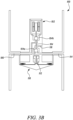
- Figure 3B shows the control assembly 100 when the switch 104 is in its second mode.
- the primary switch 104a is seated against the control chamber flow passage 114 to close the passage, and is remote from the vent passage 116 thereby opening the vent passage 116.
- the secondary switch 104b is seated against the cooling fluid flow passage 106 to close the cooling fluid flow passage 106.
- the control chamber 112 is fluidly connected with the vent passage 116.
- the switch 104 is configured to vent the control chamber 112 of the valve 110 to thereby close the valve 110.
- the actuator 102 is configured to open and close the valve 110 as the actuator 102 is configured to move the switch 104 between its first and second modes. This will open and close the valve 110 since the control chamber fluid flow passage 114 will be selectively opened and closed when the primary switch 104a moves between its first and second positions.
- the control chamber flow passage 114 may be connected to a source of fluid at a higher pressure than the pressure across the valve 110 to supply pressure to the control chamber 112 of the valve to open the valve 110. Alternatively, or additionally, the control chamber flow passage 114 may be connected to a source of fluid from an upstream side of the valve.
- the primary switching portion 104a is a 2-state 3-way switch for controlling the pressurisation or venting of the control chamber of the valve 110 (which is a 2-state valve) in this example.
- the secondary switch portion 104b is a 2-state 2-way switch for controlling the flow of cooling air.
- the switch 104 comprises a tandem switch.
- both portions 104a and 104b are configured to move together, e.g. in tandem, so that the control chamber is pressurised to open the valve concurrently with the cooling flow passage being opened.
- the control assembly 100 only provides cooling flow when the valve 110 is open.
- control assembly 100 only provides cooling flow when it is in the presence of high temperature efflux air from the valve 110. In this way, a specific fuel consumption penalty is only incurred when it is necessary to cool the controller, and wasteful parasitic cooling flows may therefore be therefore avoided.
- the control assembly 100 may be for use with a gas turbine engine, for example the engine 10 of Figures 1 and 2 .
- a gas turbine engine for example the engine 10 of Figures 1 and 2 .
- the upstream side of the valve may receive fluid from a compressor 14, 15 or from a turbine 17, 19 of the engine 10.
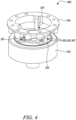
- FIG 4 shows an example valve assembly 200 which may comprise the control assembly 100 of Figures 3A and 3B .
- the valve assembly 200 comprises an upstream housing 202 and a downstream housing 204.
- One of the upstream and downstream housings 202, 204 may be moveable relative to the other one.
- Three spokes 203, 205 and 207 connect the two housings 202, 204.
- the housings 202, 204 may be part of a valve body.
- the electromechanical actuator 102 may be connected to, or comprised in, the second housing 204 and the valve 110 may be connected to, or comprised in, the first housing 202.
- the cooling fluid flow passage 106 is at least partially within one of the spokes 203, 205, 207.
- control chamber flow passage 114 is at least partially within one of the spokes 203, 205, 207.
- cooling fluid flow passage 106 is at least partially within one of the spokes 203, 205, 207 and the control chamber flow passage 114 is at least partially within another of the spokes 203, 205, 207.
- a first spoke 203 may carry air to the control chamber 112 to effect the change of state of the valve 110 (e.g. to transition between open and closed states).
- a second spoke 205 may carry the cooling air to shield the control assembly from the hot air in a downstream portion 110b of the valve 110.
- a third spoke may carry at least one wire, e.g. an electrical wire, from the coils of the actuator (in examples where the actuator comprises a solenoid) to a corresponding electrical connector on the valve 110 so that the actuator is configured to control the valve.
- the three spokes are equally spaced, with approximately (or exactly) 120 degrees between the spokes. Although three spokes are depicted any number may be used.
- spokes 203, 205 are shown (although any number of spokes may be used).
- spokes are axial spokes, but in the example of Figure 3B they are radial spokes.
- cooling passage 106 is at least partially contained in a first spoke 203 and the control chamber flow passage 114 is at least partially contained in a second spoke 205.
- the controller assembly may be located on the downstream face of the valve, e.g. outboard of the valve spokes. In which case it may not be necessary to carry the cooling flow or electrical wiring through any spokes. In such a configuration one spoke may carry the air into / out of the valve control chamber 112. As such, in one example there may only be one spoke.
- the gas turbine engine 10 of the examples of Figures 1 and 2 may comprise the valve assembly 200.
Landscapes
- Engineering & Computer Science (AREA)
- General Engineering & Computer Science (AREA)
- Mechanical Engineering (AREA)
- Chemical & Material Sciences (AREA)
- Combustion & Propulsion (AREA)
- Physics & Mathematics (AREA)
- Thermal Sciences (AREA)
- Fluid Mechanics (AREA)
- Structures Of Non-Positive Displacement Pumps (AREA)
Claims (12)
- Anordnung für ein Gasturbinentriebwerk, wobei die Anordnung Folgendes umfasst:ein Ventil (110), das zwischen einer offenen und einer geschlossenen Konfiguration bewegbar ist; undeine Steuergeräteanordnung (100), die einen elektromechanischen Aktuator (102) umfasst, der mit dem Ventil (110) gekoppelt ist; und einen einstufigen pneumatischen Strömungsschalter (104), der dazu konfiguriert ist, den elektromechanischen Aktuator (102) durch eine Zufuhr von Kühlfluid thermisch zu schützen; wobei der einstufige pneumatische Strömungsschalter (104) zwischen einem ersten Modus, in dem der Schalter dazu konfiguriert ist, einen Kühlfluidströmungskanal (106) zu öffnen, und einem zweiten Modus, in dem der Schalter dazu konfiguriert ist, den Kühlfluidströmungskanal (106) zu schließen, bewegbar ist; unddadurch gekennzeichnet, dass der elektromechanische Aktuator (102) in einem Fluidströmungsauslass (110b) des Ventils (110) angeordnet ist.
- Anordnung nach Anspruch 1, wobei der einstufige pneumatische Strömungsschalter (104), wenn er sich in dem ersten Modus befindet, dazu konfiguriert ist, einen weiteren Fluidströmungskanal (114) zu öffnen, und der Schalter (104), wenn er sich in dem zweiten Modus befindet, dazu konfiguriert ist, den weiteren Fluidströmungskanal (114) zu schließen.
- Anordnung nach Anspruch 2, wobei der weitere Fluidströmungskanal (114) mit einer Steuerkammer (112) des Ventils (110) verbunden ist.
- Anordnung nach einem vorhergehenden Anspruch, wobei der einstufige pneumatische Strömungsschalter (104), wenn er sich in dem ersten Modus befindet, dazu konfiguriert ist, zu bewirken, dass sich das Ventil (110) öffnet, und der Schalter (104), wenn er sich in dem zweiten Modus befindet, dazu konfiguriert ist, zu bewirken, dass sich das Ventil (110) schließt.
- Anordnung nach Anspruch 3 oder 4, wobei der einstufige pneumatische Strömungsschalter (104), wenn er sich in dem zweiten Modus befindet, dazu konfiguriert ist, einen Entlüftungsströmungskanal (116) zu öffnen, sodass die Steuerkammer (112) des Ventils (110) in Fluidkommunikation mit dem Entlüftungsströmungskanal (116) steht.
- Anordnung nach einem vorhergehenden Anspruch, wobei der elektromechanische Aktuator (102) dazu konfiguriert ist, zu bewirken, dass der Schalter (104) zwischen seinem ersten und zweiten Modus wechselt, wodurch er dazu konfiguriert ist, zu bewirken, dass das Ventil (110) zwischen einer offenen und einer geschlossenen Konfiguration wechselt.
- Anordnung nach einem der Ansprüche 3 bis 6, wenn abhängig von Anspruch 2, wobei der weitere Strömungskanal (114) mit einer Fluidquelle mit einem höheren Druck als dem Druck über dem Ventil (110) verbunden ist, um dadurch die Steuerkammer (112) des Ventils (110) unter Druck zu setzen.
- Anordnung nach Anspruch 7, wobei der weitere Strömungskanal (114) mit einer Fluidquelle von einer stromaufwärts gelegenen Seite des Ventils (110) verbunden ist.
- Anordnung nach einem vorhergehenden Anspruch, wobei der elektromechanische Aktuator (102) einen Elektromagneten umfasst.
- Gasturbinentriebwerk (10) für ein Luftfahrzeug, wobei das Gasturbinentriebwerk Folgendes umfasst:einen Triebwerkskern (11), der eine Turbine (19), einen Verdichter (14) und eine Kernwelle (26) umfasst, die die Turbine (19) mit dem Verdichter (14) verbindet;einen Fan (23), der sich stromaufwärts des Triebwerkskerns (11) befindet, wobei der Fan (23) eine Vielzahl von Fanschaufeln umfasst; undeine Anordnung nach einem vorhergehenden Anspruch.
- Gasturbinentriebwerk (10) nach Anspruch 10, wobei die Steuergeräteanordnung (100) der Anordnung innerhalb eines Ventilkörpers angeordnet ist, und wobei mindestens eine Speiche den Ventilkörper mit dem elektromechanischen Aktuator (102) verbindet; wobei sich der Kühlfluidströmungskanal (106) mindestens teilweise innerhalb einer Speiche befindet.
- Gasturbinentriebwerk (10) nach Anspruch 10 oder 11, wobei die Steuergeräteanordnung (100) der Anordnung innerhalb eines/des Ventilkörpers angeordnet ist, wobei der Ventilkörper ein Ventil (110) umfasst, das eine Steuerkammer (112) aufweist, wobei mindestens eine Speiche den Ventilkörper mit dem elektromechanischen Aktuator (102) verbindet und wobei eine Druckquelle mit der Ventilsteuerkammer (112) verbunden ist, wobei sich die Druckquelle mindestens teilweise innerhalb einer Speiche befindet.
Applications Claiming Priority (1)
| Application Number | Priority Date | Filing Date | Title |
|---|---|---|---|
| GBGB1816364.2A GB201816364D0 (en) | 2018-10-08 | 2018-10-08 | A controller assembley |
Publications (2)
| Publication Number | Publication Date |
|---|---|
| EP3636896A1 EP3636896A1 (de) | 2020-04-15 |
| EP3636896B1 true EP3636896B1 (de) | 2024-08-14 |
Family
ID=64394876
Family Applications (1)
| Application Number | Title | Priority Date | Filing Date |
|---|---|---|---|
| EP19196630.8A Active EP3636896B1 (de) | 2018-10-08 | 2019-09-11 | Steuergeräteanordnung |
Country Status (3)
| Country | Link |
|---|---|
| US (1) | US11215295B2 (de) |
| EP (1) | EP3636896B1 (de) |
| GB (1) | GB201816364D0 (de) |
Families Citing this family (4)
| Publication number | Priority date | Publication date | Assignee | Title |
|---|---|---|---|---|
| GB202117158D0 (en) | 2021-11-29 | 2022-01-12 | Rolls Royce Plc | Valve assembly |
| US20230184349A1 (en) * | 2021-12-15 | 2023-06-15 | Hamilton Sundstrand Corporation | Four way solenoid |
| US20230312084A1 (en) * | 2022-04-04 | 2023-10-05 | Honeywell International Inc. | Aircraft high-voltage actuator controller with embedded bidirectional dc/dc converter |
| BE1030919B1 (fr) * | 2022-09-28 | 2024-04-30 | Safran Aero Boosters | Electrovanne et équipement avec l’électrovanne |
Family Cites Families (37)
| Publication number | Priority date | Publication date | Assignee | Title |
|---|---|---|---|---|
| GB636115A (en) | 1944-04-15 | 1950-04-26 | United Aircraft Corp | Improvements in or relating to pressure controls for turbines |
| US2679856A (en) * | 1951-01-29 | 1954-06-01 | Gerritsen Jacobus Johannes | Pilot operated valve for controlling the flow of fluids |
| FR1088872A (fr) | 1955-03-08 | 1955-03-11 | Flight Refueling Ltd | Perfectionnements apportés aux dispositifs à soupape pour régler le débit de fluides |
| US3087511A (en) | 1960-08-24 | 1963-04-30 | United Aircraft Corp | Sequence operating valve system |
| US3092132A (en) * | 1961-05-15 | 1963-06-04 | Rotax Ltd | Compressed air or other gas control valves |
| US3432139A (en) | 1961-10-12 | 1969-03-11 | Robertson Co H H | Extensible plug valve |
| US3204969A (en) | 1963-04-26 | 1965-09-07 | Williams Res Corp | High pressure dynamic seal |
| US3235270A (en) | 1963-04-26 | 1966-02-15 | Williams Res Corp | High pressure regenerator seal |
| US3297047A (en) * | 1964-03-17 | 1967-01-10 | Vapor Corp | Valve assembly |
| GB1125102A (en) | 1965-03-03 | 1968-08-28 | Westland Aircraft Ltd | A solenoid actuator and a solen oid actuated fluid control valve |
| US3380469A (en) * | 1965-07-16 | 1968-04-30 | Vapor Corp | Valve assembly |
| DE1775332A1 (de) | 1968-07-30 | 1971-05-19 | Erno Raumfahrttechnik Gmbh | Absperrventil |
| US3540462A (en) * | 1968-08-02 | 1970-11-17 | Avco Corp | Miniaturized flow control valve |
| FR2092293A5 (de) | 1970-04-15 | 1971-01-21 | Nippon Oil Seal Ind Co | |
| US3750693A (en) * | 1971-10-13 | 1973-08-07 | Xar Ind Inc | Solenoid operated valve |
| US3825026A (en) * | 1973-06-01 | 1974-07-23 | Vapor Corp | Inline valve |
| US3792716A (en) * | 1973-06-13 | 1974-02-19 | Vapor Corp | Inline valve with reverse pressure closing means |
| US4057360A (en) | 1976-06-10 | 1977-11-08 | Hollymatic Corporation | Pressure gas engine |
| DE3938905A1 (de) | 1989-11-24 | 1991-05-29 | Bmw Rolls Royce Gmbh | Hydraulisches druckbegrenzungsventil |
| US6167869B1 (en) * | 1997-11-03 | 2001-01-02 | Caterpillar Inc. | Fuel injector utilizing a multiple current level solenoid |
| US6116570A (en) * | 1998-03-30 | 2000-09-12 | Siemens Automotive Corporation | Electromagnetic actuator with internal oil system and improved hydraulic lash adjuster |
| JP4300345B2 (ja) | 2002-09-02 | 2009-07-22 | 株式会社フジキン | 制御器 |
| EP1431639B1 (de) | 2002-12-19 | 2007-11-14 | Techspace Aero S.A. | Ventil mit integriertem Antrieb |
| US8047452B2 (en) * | 2004-04-26 | 2011-11-01 | Tenneco Automotive Operating Company Inc. | Method and apparatus for injecting atomized fluids |
| US20060064982A1 (en) | 2004-09-30 | 2006-03-30 | Mitten Manufacturing | Valve for dynamic control of fuel flow rate in gas turbine power plant, power plant and components thereof employing such valve, and method of constructing such valve |
| KR20070030612A (ko) | 2005-09-13 | 2007-03-16 | 삼성전자주식회사 | 용접형 벨로우즈를 갖는 벨로우즈 밸브 |
| US20130019585A1 (en) | 2007-05-11 | 2013-01-24 | Brian Merry | Variable fan inlet guide vane for turbine engine |
| CN201277378Y (zh) | 2008-10-17 | 2009-07-22 | 浙江派沃自控仪表有限公司 | 卫生级波纹管密封气动角型调节阀 |
| US8267122B2 (en) * | 2009-06-30 | 2012-09-18 | Ge Aviation Systems Llc | Method and systems for bleed air supply |
| US8656941B1 (en) * | 2010-01-11 | 2014-02-25 | Jansen's Aircraft System Controls, Inc. | Flow control valve |
| JP2012237426A (ja) | 2011-05-13 | 2012-12-06 | Smc Corp | 真空弁用ベローズ |
| KR101507461B1 (ko) | 2013-10-31 | 2015-04-01 | 동아대학교 산학협력단 | 벨로우즈 타입 안전밸브 |
| CA2975264C (en) * | 2015-02-16 | 2023-08-22 | Dukes Aerospace, Inc. | Redundant valve system |
| US10180106B2 (en) * | 2016-05-17 | 2019-01-15 | Hamilton Sundstrand Corporation | Solenoids for gas turbine engine bleed valves |
| US10273884B2 (en) | 2016-06-09 | 2019-04-30 | Hamilton Sundstrand Corporation | Altitude compensating bleed valve |
| US10738712B2 (en) | 2017-01-27 | 2020-08-11 | General Electric Company | Pneumatically-actuated bypass valve |
| FR3079888B1 (fr) * | 2018-04-04 | 2021-07-30 | Safran Aircraft Engines | Controleur pneumatique pour la commande d'une vanne de decharge |
-
2018
- 2018-10-08 GB GBGB1816364.2A patent/GB201816364D0/en not_active Ceased
-
2019
- 2019-09-11 EP EP19196630.8A patent/EP3636896B1/de active Active
- 2019-09-24 US US16/580,046 patent/US11215295B2/en active Active
Also Published As
| Publication number | Publication date |
|---|---|
| US11215295B2 (en) | 2022-01-04 |
| EP3636896A1 (de) | 2020-04-15 |
| GB201816364D0 (en) | 2018-11-28 |
| US20200109796A1 (en) | 2020-04-09 |
Similar Documents
| Publication | Publication Date | Title |
|---|---|---|
| US10583933B2 (en) | Method and apparatus for undercowl flow diversion cooling | |
| EP3135920B1 (de) | Verdichter mit variablem Druckverhältnis | |
| EP3636896B1 (de) | Steuergeräteanordnung | |
| EP3693572B1 (de) | Hilfskraft-motorstartentlüftungssystem | |
| US11162458B2 (en) | Ventilation and extinguishing device for a gas turbine engine | |
| EP3572660B1 (de) | Lufteinlasssystem | |
| EP3647566B1 (de) | Steuersystem für einen gasturbinenmotor | |
| US20200290741A1 (en) | Gas turbine engine bleed duct | |
| US20200239146A1 (en) | De-icing system | |
| US11732600B2 (en) | Gas turbine engine actuation device | |
| EP3835563B1 (de) | Klimaanlage im flugzeug | |
| EP3569840B1 (de) | Gasturbinentriebwerk | |
| US20240026822A1 (en) | Cooling air delivery system and methods thereof | |
| EP3388638A1 (de) | Eitschaufelanordnung eines gasturbinenmotors | |
| US12110903B2 (en) | Variable pitch fan of a gas turbine engine | |
| US20200240289A1 (en) | De-icing system | |
| EP3708807B1 (de) | Lamellensystem | |
| US11248535B2 (en) | Gas turbine engine with compressor bleed valve including at least two open positions | |
| EP3693576B1 (de) | Ventilanordnung für ein kraftstoffsystem | |
| US20200025099A1 (en) | Gas turbine engine | |
| GB2594958A (en) | Zone ventilation arrangement |
Legal Events
| Date | Code | Title | Description |
|---|---|---|---|
| PUAI | Public reference made under article 153(3) epc to a published international application that has entered the european phase |
Free format text: ORIGINAL CODE: 0009012 |
|
| STAA | Information on the status of an ep patent application or granted ep patent |
Free format text: STATUS: THE APPLICATION HAS BEEN PUBLISHED |
|
| AK | Designated contracting states |
Kind code of ref document: A1 Designated state(s): AL AT BE BG CH CY CZ DE DK EE ES FI FR GB GR HR HU IE IS IT LI LT LU LV MC MK MT NL NO PL PT RO RS SE SI SK SM TR |
|
| AX | Request for extension of the european patent |
Extension state: BA ME |
|
| STAA | Information on the status of an ep patent application or granted ep patent |
Free format text: STATUS: REQUEST FOR EXAMINATION WAS MADE |
|
| 17P | Request for examination filed |
Effective date: 20201008 |
|
| RBV | Designated contracting states (corrected) |
Designated state(s): AL AT BE BG CH CY CZ DE DK EE ES FI FR GB GR HR HU IE IS IT LI LT LU LV MC MK MT NL NO PL PT RO RS SE SI SK SM TR |
|
| STAA | Information on the status of an ep patent application or granted ep patent |
Free format text: STATUS: EXAMINATION IS IN PROGRESS |
|
| 17Q | First examination report despatched |
Effective date: 20220323 |
|
| GRAP | Despatch of communication of intention to grant a patent |
Free format text: ORIGINAL CODE: EPIDOSNIGR1 |
|
| STAA | Information on the status of an ep patent application or granted ep patent |
Free format text: STATUS: GRANT OF PATENT IS INTENDED |
|
| GRAJ | Information related to disapproval of communication of intention to grant by the applicant or resumption of examination proceedings by the epo deleted |
Free format text: ORIGINAL CODE: EPIDOSDIGR1 |
|
| STAA | Information on the status of an ep patent application or granted ep patent |
Free format text: STATUS: EXAMINATION IS IN PROGRESS |
|
| RIC1 | Information provided on ipc code assigned before grant |
Ipc: F16K 11/048 20060101ALI20240327BHEP Ipc: F16K 11/044 20060101ALI20240327BHEP Ipc: F16K 31/42 20060101ALI20240327BHEP Ipc: F16K 31/122 20060101ALI20240327BHEP Ipc: F16K 31/06 20060101ALI20240327BHEP Ipc: F16K 49/00 20060101ALI20240327BHEP Ipc: F02C 9/18 20060101ALI20240327BHEP Ipc: F02C 6/08 20060101AFI20240327BHEP |
|
| INTG | Intention to grant announced |
Effective date: 20240417 |
|
| INTC | Intention to grant announced (deleted) | ||
| GRAP | Despatch of communication of intention to grant a patent |
Free format text: ORIGINAL CODE: EPIDOSNIGR1 |
|
| STAA | Information on the status of an ep patent application or granted ep patent |
Free format text: STATUS: GRANT OF PATENT IS INTENDED |
|
| GRAS | Grant fee paid |
Free format text: ORIGINAL CODE: EPIDOSNIGR3 |
|
| GRAA | (expected) grant |
Free format text: ORIGINAL CODE: 0009210 |
|
| STAA | Information on the status of an ep patent application or granted ep patent |
Free format text: STATUS: THE PATENT HAS BEEN GRANTED |
|
| INTG | Intention to grant announced |
Effective date: 20240618 |
|
| P01 | Opt-out of the competence of the unified patent court (upc) registered |
Free format text: CASE NUMBER: APP_38637/2024 Effective date: 20240627 |
|
| AK | Designated contracting states |
Kind code of ref document: B1 Designated state(s): AL AT BE BG CH CY CZ DE DK EE ES FI FR GB GR HR HU IE IS IT LI LT LU LV MC MK MT NL NO PL PT RO RS SE SI SK SM TR |
|
| REG | Reference to a national code |
Ref country code: GB Ref legal event code: FG4D |
|
| REG | Reference to a national code |
Ref country code: CH Ref legal event code: EP |
|
| REG | Reference to a national code |
Ref country code: DE Ref legal event code: R096 Ref document number: 602019056906 Country of ref document: DE |
|
| REG | Reference to a national code |
Ref country code: IE Ref legal event code: FG4D |
|
| REG | Reference to a national code |
Ref country code: LT Ref legal event code: MG9D |
|
| REG | Reference to a national code |
Ref country code: NL Ref legal event code: MP Effective date: 20240814 |
|
| PG25 | Lapsed in a contracting state [announced via postgrant information from national office to epo] |
Ref country code: NO Free format text: LAPSE BECAUSE OF FAILURE TO SUBMIT A TRANSLATION OF THE DESCRIPTION OR TO PAY THE FEE WITHIN THE PRESCRIBED TIME-LIMIT Effective date: 20241114 |
|
| REG | Reference to a national code |
Ref country code: AT Ref legal event code: MK05 Ref document number: 1713496 Country of ref document: AT Kind code of ref document: T Effective date: 20240814 |
|
| PG25 | Lapsed in a contracting state [announced via postgrant information from national office to epo] |
Ref country code: FI Free format text: LAPSE BECAUSE OF FAILURE TO SUBMIT A TRANSLATION OF THE DESCRIPTION OR TO PAY THE FEE WITHIN THE PRESCRIBED TIME-LIMIT Effective date: 20240814 Ref country code: NL Free format text: LAPSE BECAUSE OF FAILURE TO SUBMIT A TRANSLATION OF THE DESCRIPTION OR TO PAY THE FEE WITHIN THE PRESCRIBED TIME-LIMIT Effective date: 20240814 Ref country code: PT Free format text: LAPSE BECAUSE OF FAILURE TO SUBMIT A TRANSLATION OF THE DESCRIPTION OR TO PAY THE FEE WITHIN THE PRESCRIBED TIME-LIMIT Effective date: 20241216 Ref country code: PL Free format text: LAPSE BECAUSE OF FAILURE TO SUBMIT A TRANSLATION OF THE DESCRIPTION OR TO PAY THE FEE WITHIN THE PRESCRIBED TIME-LIMIT Effective date: 20240814 Ref country code: GR Free format text: LAPSE BECAUSE OF FAILURE TO SUBMIT A TRANSLATION OF THE DESCRIPTION OR TO PAY THE FEE WITHIN THE PRESCRIBED TIME-LIMIT Effective date: 20241115 |
|
| PG25 | Lapsed in a contracting state [announced via postgrant information from national office to epo] |
Ref country code: BG Free format text: LAPSE BECAUSE OF FAILURE TO SUBMIT A TRANSLATION OF THE DESCRIPTION OR TO PAY THE FEE WITHIN THE PRESCRIBED TIME-LIMIT Effective date: 20240814 |
|
| PG25 | Lapsed in a contracting state [announced via postgrant information from national office to epo] |
Ref country code: LV Free format text: LAPSE BECAUSE OF FAILURE TO SUBMIT A TRANSLATION OF THE DESCRIPTION OR TO PAY THE FEE WITHIN THE PRESCRIBED TIME-LIMIT Effective date: 20240814 |
|
| PG25 | Lapsed in a contracting state [announced via postgrant information from national office to epo] |
Ref country code: IS Free format text: LAPSE BECAUSE OF FAILURE TO SUBMIT A TRANSLATION OF THE DESCRIPTION OR TO PAY THE FEE WITHIN THE PRESCRIBED TIME-LIMIT Effective date: 20241214 Ref country code: AT Free format text: LAPSE BECAUSE OF FAILURE TO SUBMIT A TRANSLATION OF THE DESCRIPTION OR TO PAY THE FEE WITHIN THE PRESCRIBED TIME-LIMIT Effective date: 20240814 |
|
| PG25 | Lapsed in a contracting state [announced via postgrant information from national office to epo] |
Ref country code: HR Free format text: LAPSE BECAUSE OF FAILURE TO SUBMIT A TRANSLATION OF THE DESCRIPTION OR TO PAY THE FEE WITHIN THE PRESCRIBED TIME-LIMIT Effective date: 20240814 |
|
| PG25 | Lapsed in a contracting state [announced via postgrant information from national office to epo] |
Ref country code: ES Free format text: LAPSE BECAUSE OF FAILURE TO SUBMIT A TRANSLATION OF THE DESCRIPTION OR TO PAY THE FEE WITHIN THE PRESCRIBED TIME-LIMIT Effective date: 20240814 Ref country code: RS Free format text: LAPSE BECAUSE OF FAILURE TO SUBMIT A TRANSLATION OF THE DESCRIPTION OR TO PAY THE FEE WITHIN THE PRESCRIBED TIME-LIMIT Effective date: 20241114 |
|
| PG25 | Lapsed in a contracting state [announced via postgrant information from national office to epo] |
Ref country code: RS Free format text: LAPSE BECAUSE OF FAILURE TO SUBMIT A TRANSLATION OF THE DESCRIPTION OR TO PAY THE FEE WITHIN THE PRESCRIBED TIME-LIMIT Effective date: 20241114 Ref country code: PT Free format text: LAPSE BECAUSE OF FAILURE TO SUBMIT A TRANSLATION OF THE DESCRIPTION OR TO PAY THE FEE WITHIN THE PRESCRIBED TIME-LIMIT Effective date: 20241216 Ref country code: PL Free format text: LAPSE BECAUSE OF FAILURE TO SUBMIT A TRANSLATION OF THE DESCRIPTION OR TO PAY THE FEE WITHIN THE PRESCRIBED TIME-LIMIT Effective date: 20240814 Ref country code: NO Free format text: LAPSE BECAUSE OF FAILURE TO SUBMIT A TRANSLATION OF THE DESCRIPTION OR TO PAY THE FEE WITHIN THE PRESCRIBED TIME-LIMIT Effective date: 20241114 Ref country code: NL Free format text: LAPSE BECAUSE OF FAILURE TO SUBMIT A TRANSLATION OF THE DESCRIPTION OR TO PAY THE FEE WITHIN THE PRESCRIBED TIME-LIMIT Effective date: 20240814 Ref country code: LV Free format text: LAPSE BECAUSE OF FAILURE TO SUBMIT A TRANSLATION OF THE DESCRIPTION OR TO PAY THE FEE WITHIN THE PRESCRIBED TIME-LIMIT Effective date: 20240814 Ref country code: IS Free format text: LAPSE BECAUSE OF FAILURE TO SUBMIT A TRANSLATION OF THE DESCRIPTION OR TO PAY THE FEE WITHIN THE PRESCRIBED TIME-LIMIT Effective date: 20241214 Ref country code: HR Free format text: LAPSE BECAUSE OF FAILURE TO SUBMIT A TRANSLATION OF THE DESCRIPTION OR TO PAY THE FEE WITHIN THE PRESCRIBED TIME-LIMIT Effective date: 20240814 Ref country code: GR Free format text: LAPSE BECAUSE OF FAILURE TO SUBMIT A TRANSLATION OF THE DESCRIPTION OR TO PAY THE FEE WITHIN THE PRESCRIBED TIME-LIMIT Effective date: 20241115 Ref country code: FI Free format text: LAPSE BECAUSE OF FAILURE TO SUBMIT A TRANSLATION OF THE DESCRIPTION OR TO PAY THE FEE WITHIN THE PRESCRIBED TIME-LIMIT Effective date: 20240814 Ref country code: ES Free format text: LAPSE BECAUSE OF FAILURE TO SUBMIT A TRANSLATION OF THE DESCRIPTION OR TO PAY THE FEE WITHIN THE PRESCRIBED TIME-LIMIT Effective date: 20240814 Ref country code: BG Free format text: LAPSE BECAUSE OF FAILURE TO SUBMIT A TRANSLATION OF THE DESCRIPTION OR TO PAY THE FEE WITHIN THE PRESCRIBED TIME-LIMIT Effective date: 20240814 Ref country code: AT Free format text: LAPSE BECAUSE OF FAILURE TO SUBMIT A TRANSLATION OF THE DESCRIPTION OR TO PAY THE FEE WITHIN THE PRESCRIBED TIME-LIMIT Effective date: 20240814 |
|
| PG25 | Lapsed in a contracting state [announced via postgrant information from national office to epo] |
Ref country code: SM Free format text: LAPSE BECAUSE OF FAILURE TO SUBMIT A TRANSLATION OF THE DESCRIPTION OR TO PAY THE FEE WITHIN THE PRESCRIBED TIME-LIMIT Effective date: 20240814 Ref country code: DK Free format text: LAPSE BECAUSE OF FAILURE TO SUBMIT A TRANSLATION OF THE DESCRIPTION OR TO PAY THE FEE WITHIN THE PRESCRIBED TIME-LIMIT Effective date: 20240814 Ref country code: RO Free format text: LAPSE BECAUSE OF FAILURE TO SUBMIT A TRANSLATION OF THE DESCRIPTION OR TO PAY THE FEE WITHIN THE PRESCRIBED TIME-LIMIT Effective date: 20240814 |
|
| PG25 | Lapsed in a contracting state [announced via postgrant information from national office to epo] |
Ref country code: EE Free format text: LAPSE BECAUSE OF FAILURE TO SUBMIT A TRANSLATION OF THE DESCRIPTION OR TO PAY THE FEE WITHIN THE PRESCRIBED TIME-LIMIT Effective date: 20240814 |
|
| PG25 | Lapsed in a contracting state [announced via postgrant information from national office to epo] |
Ref country code: CZ Free format text: LAPSE BECAUSE OF FAILURE TO SUBMIT A TRANSLATION OF THE DESCRIPTION OR TO PAY THE FEE WITHIN THE PRESCRIBED TIME-LIMIT Effective date: 20240814 |
|
| PG25 | Lapsed in a contracting state [announced via postgrant information from national office to epo] |
Ref country code: IT Free format text: LAPSE BECAUSE OF FAILURE TO SUBMIT A TRANSLATION OF THE DESCRIPTION OR TO PAY THE FEE WITHIN THE PRESCRIBED TIME-LIMIT Effective date: 20240814 Ref country code: SK Free format text: LAPSE BECAUSE OF FAILURE TO SUBMIT A TRANSLATION OF THE DESCRIPTION OR TO PAY THE FEE WITHIN THE PRESCRIBED TIME-LIMIT Effective date: 20240814 |
|
| REG | Reference to a national code |
Ref country code: CH Ref legal event code: PL |
|
| REG | Reference to a national code |
Ref country code: DE Ref legal event code: R097 Ref document number: 602019056906 Country of ref document: DE |
|
| PG25 | Lapsed in a contracting state [announced via postgrant information from national office to epo] |
Ref country code: LU Free format text: LAPSE BECAUSE OF NON-PAYMENT OF DUE FEES Effective date: 20240911 |
|
| PLBE | No opposition filed within time limit |
Free format text: ORIGINAL CODE: 0009261 |
|
| STAA | Information on the status of an ep patent application or granted ep patent |
Free format text: STATUS: NO OPPOSITION FILED WITHIN TIME LIMIT |
|
| PG25 | Lapsed in a contracting state [announced via postgrant information from national office to epo] |
Ref country code: MC Free format text: LAPSE BECAUSE OF FAILURE TO SUBMIT A TRANSLATION OF THE DESCRIPTION OR TO PAY THE FEE WITHIN THE PRESCRIBED TIME-LIMIT Effective date: 20240814 |
|
| REG | Reference to a national code |
Ref country code: BE Ref legal event code: MM Effective date: 20240930 |
|
| PG25 | Lapsed in a contracting state [announced via postgrant information from national office to epo] |
Ref country code: BE Free format text: LAPSE BECAUSE OF NON-PAYMENT OF DUE FEES Effective date: 20240930 |
|
| 26N | No opposition filed |
Effective date: 20250515 |
|
| PG25 | Lapsed in a contracting state [announced via postgrant information from national office to epo] |
Ref country code: CH Free format text: LAPSE BECAUSE OF NON-PAYMENT OF DUE FEES Effective date: 20240930 |
|
| PG25 | Lapsed in a contracting state [announced via postgrant information from national office to epo] |
Ref country code: IE Free format text: LAPSE BECAUSE OF NON-PAYMENT OF DUE FEES Effective date: 20240911 |
|
| PG25 | Lapsed in a contracting state [announced via postgrant information from national office to epo] |
Ref country code: SE Free format text: LAPSE BECAUSE OF FAILURE TO SUBMIT A TRANSLATION OF THE DESCRIPTION OR TO PAY THE FEE WITHIN THE PRESCRIBED TIME-LIMIT Effective date: 20240814 |
|
| PGFP | Annual fee paid to national office [announced via postgrant information from national office to epo] |
Ref country code: DE Payment date: 20250926 Year of fee payment: 7 |
|
| PGFP | Annual fee paid to national office [announced via postgrant information from national office to epo] |
Ref country code: GB Payment date: 20250923 Year of fee payment: 7 |
|
| PGFP | Annual fee paid to national office [announced via postgrant information from national office to epo] |
Ref country code: FR Payment date: 20250925 Year of fee payment: 7 |
|
| PG25 | Lapsed in a contracting state [announced via postgrant information from national office to epo] |
Ref country code: CY Free format text: LAPSE BECAUSE OF FAILURE TO SUBMIT A TRANSLATION OF THE DESCRIPTION OR TO PAY THE FEE WITHIN THE PRESCRIBED TIME-LIMIT; INVALID AB INITIO Effective date: 20190911 |
|
| PG25 | Lapsed in a contracting state [announced via postgrant information from national office to epo] |
Ref country code: HU Free format text: LAPSE BECAUSE OF FAILURE TO SUBMIT A TRANSLATION OF THE DESCRIPTION OR TO PAY THE FEE WITHIN THE PRESCRIBED TIME-LIMIT; INVALID AB INITIO Effective date: 20190911 |