EP3637120A1 - Appareil et procédé d'estimation d'état de charge de batterie - Google Patents
Appareil et procédé d'estimation d'état de charge de batterie Download PDFInfo
- Publication number
- EP3637120A1 EP3637120A1 EP18867378.4A EP18867378A EP3637120A1 EP 3637120 A1 EP3637120 A1 EP 3637120A1 EP 18867378 A EP18867378 A EP 18867378A EP 3637120 A1 EP3637120 A1 EP 3637120A1
- Authority
- EP
- European Patent Office
- Prior art keywords
- battery
- soc
- voltage
- voltage region
- processor
- Prior art date
- Legal status (The legal status is an assumption and is not a legal conclusion. Google has not performed a legal analysis and makes no representation as to the accuracy of the status listed.)
- Granted
Links
Images




Classifications
-
- G—PHYSICS
- G01—MEASURING; TESTING
- G01R—MEASURING ELECTRIC VARIABLES; MEASURING MAGNETIC VARIABLES
- G01R31/00—Arrangements for testing electric properties; Arrangements for locating electric faults; Arrangements for electrical testing characterised by what is being tested not provided for elsewhere
- G01R31/36—Arrangements for testing, measuring or monitoring the electrical condition of accumulators or electric batteries, e.g. capacity or state of charge [SoC]
- G01R31/367—Software therefor, e.g. for battery testing using modelling or look-up tables
-
- G—PHYSICS
- G01—MEASURING; TESTING
- G01R—MEASURING ELECTRIC VARIABLES; MEASURING MAGNETIC VARIABLES
- G01R31/00—Arrangements for testing electric properties; Arrangements for locating electric faults; Arrangements for electrical testing characterised by what is being tested not provided for elsewhere
- G01R31/36—Arrangements for testing, measuring or monitoring the electrical condition of accumulators or electric batteries, e.g. capacity or state of charge [SoC]
- G01R31/382—Arrangements for monitoring battery or accumulator variables, e.g. SoC
-
- G—PHYSICS
- G01—MEASURING; TESTING
- G01R—MEASURING ELECTRIC VARIABLES; MEASURING MAGNETIC VARIABLES
- G01R19/00—Arrangements for measuring currents or voltages or for indicating presence or sign thereof
- G01R19/12—Measuring rate of change
-
- G—PHYSICS
- G01—MEASURING; TESTING
- G01R—MEASURING ELECTRIC VARIABLES; MEASURING MAGNETIC VARIABLES
- G01R19/00—Arrangements for measuring currents or voltages or for indicating presence or sign thereof
- G01R19/165—Indicating that current or voltage is either above or below a predetermined value or within or outside a predetermined range of values
- G01R19/16528—Indicating that current or voltage is either above or below a predetermined value or within or outside a predetermined range of values using digital techniques or performing arithmetic operations
-
- G—PHYSICS
- G01—MEASURING; TESTING
- G01R—MEASURING ELECTRIC VARIABLES; MEASURING MAGNETIC VARIABLES
- G01R19/00—Arrangements for measuring currents or voltages or for indicating presence or sign thereof
- G01R19/165—Indicating that current or voltage is either above or below a predetermined value or within or outside a predetermined range of values
- G01R19/16533—Indicating that current or voltage is either above or below a predetermined value or within or outside a predetermined range of values characterised by the application
- G01R19/16538—Indicating that current or voltage is either above or below a predetermined value or within or outside a predetermined range of values characterised by the application in AC or DC supplies
- G01R19/16542—Indicating that current or voltage is either above or below a predetermined value or within or outside a predetermined range of values characterised by the application in AC or DC supplies for batteries
-
- G—PHYSICS
- G01—MEASURING; TESTING
- G01R—MEASURING ELECTRIC VARIABLES; MEASURING MAGNETIC VARIABLES
- G01R31/00—Arrangements for testing electric properties; Arrangements for locating electric faults; Arrangements for electrical testing characterised by what is being tested not provided for elsewhere
- G01R31/36—Arrangements for testing, measuring or monitoring the electrical condition of accumulators or electric batteries, e.g. capacity or state of charge [SoC]
-
- G—PHYSICS
- G01—MEASURING; TESTING
- G01R—MEASURING ELECTRIC VARIABLES; MEASURING MAGNETIC VARIABLES
- G01R31/00—Arrangements for testing electric properties; Arrangements for locating electric faults; Arrangements for electrical testing characterised by what is being tested not provided for elsewhere
- G01R31/36—Arrangements for testing, measuring or monitoring the electrical condition of accumulators or electric batteries, e.g. capacity or state of charge [SoC]
- G01R31/382—Arrangements for monitoring battery or accumulator variables, e.g. SoC
- G01R31/3842—Arrangements for monitoring battery or accumulator variables, e.g. SoC combining voltage and current measurements
-
- H—ELECTRICITY
- H01—ELECTRIC ELEMENTS
- H01M—PROCESSES OR MEANS, e.g. BATTERIES, FOR THE DIRECT CONVERSION OF CHEMICAL ENERGY INTO ELECTRICAL ENERGY
- H01M10/00—Secondary cells; Manufacture thereof
- H01M10/42—Methods or arrangements for servicing or maintenance of secondary cells or secondary half-cells
-
- H—ELECTRICITY
- H01—ELECTRIC ELEMENTS
- H01M—PROCESSES OR MEANS, e.g. BATTERIES, FOR THE DIRECT CONVERSION OF CHEMICAL ENERGY INTO ELECTRICAL ENERGY
- H01M10/00—Secondary cells; Manufacture thereof
- H01M10/42—Methods or arrangements for servicing or maintenance of secondary cells or secondary half-cells
- H01M10/425—Structural combination with electronic components, e.g. electronic circuits integrated to the outside of the casing
- H01M10/4257—Smart batteries, e.g. electronic circuits inside the housing of the cells or batteries
-
- H—ELECTRICITY
- H01—ELECTRIC ELEMENTS
- H01M—PROCESSES OR MEANS, e.g. BATTERIES, FOR THE DIRECT CONVERSION OF CHEMICAL ENERGY INTO ELECTRICAL ENERGY
- H01M10/00—Secondary cells; Manufacture thereof
- H01M10/42—Methods or arrangements for servicing or maintenance of secondary cells or secondary half-cells
- H01M10/48—Accumulators combined with arrangements for measuring, testing or indicating the condition of cells, e.g. the level or density of the electrolyte
-
- H—ELECTRICITY
- H01—ELECTRIC ELEMENTS
- H01M—PROCESSES OR MEANS, e.g. BATTERIES, FOR THE DIRECT CONVERSION OF CHEMICAL ENERGY INTO ELECTRICAL ENERGY
- H01M50/00—Constructional details or processes of manufacture of the non-active parts of electrochemical cells other than fuel cells, e.g. hybrid cells
- H01M50/50—Current conducting connections for cells or batteries
- H01M50/569—Constructional details of current conducting connections for detecting conditions inside cells or batteries, e.g. details of voltage sensing terminals
Definitions
- the present disclosure relates to an apparatus and method for estimating a state of charge (SOC) of a battery, and more particularly, to an apparatus and method for estimating a SOC of a battery by using a first SOC calculated for each charge/discharge cycle of the battery and a second SOC calculated using an equivalent circuit model.
- SOC state of charge
- Batteries commercially available at the present include nickel-cadmium batteries, nickel hydrogen batteries, nickel-zinc batteries, lithium batteries and the like.
- the lithium batteries are in the limelight since they have almost no memory effect compared to nickel-based batteries and also have very low self-discharging rate and high energy density.
- the SOC is a parameter representing a relative ratio of capacity at the present to a maximum capacity representing the electrical energy stored in the battery when the battery is fully charged.
- the SOC may be expressed as 0 to 1 or 0% to 100%.
- An equivalent circuit model is representatively used to estimate the SOC of a battery.
- the equivalent circuit model is designed to simulate electrical operating characteristics of a battery.
- the battery has nonlinear characteristics depending on the operating condition, and it is very difficult to design the equivalent circuit model to perfectly simulate the nonlinear characteristics of the battery.
- the SOC with nonlinearity is estimated in a specific voltage region according to the operation state of the battery to be estimated.
- the accuracy of the estimated SOC of the battery is lowered.
- the present disclosure is designed to solve the problems of the related art, and therefore the present disclosure is directed to providing an apparatus and method for estimating a SOC of a battery, which sets a battery voltage having a minimum SOC deviation of first SOCs calculated for each charge/discharge cycle of the battery as a first reference voltage, estimates a SOC of the battery as a first SOC in a battery voltage region equal to or lower than the first reference voltage, and estimates a SOC of the battery in a battery voltage region higher than the first reference voltage as a second SOC calculated using an equivalent circuit model.
- an apparatus for estimating a state of charge (SOC) of a battery comprising: a sensing unit configured to measure voltage, current and temperature of a battery; and a processor operably coupled to the sensing unit.
- SOC state of charge
- the processor may be configured to perform: setting a first reference voltage based on a first SOC according to a voltage of the battery, which is calculated in advance using the current of the battery measured at every charge/discharge cycle of the battery; calculating a second SOC according to the voltage of the battery using an equivalent circuit model corresponding to the battery; setting a voltage region of the battery as a first voltage region and a second voltage region based on the first reference voltage; and estimating a SOC of the battery in each of the first voltage region and the second voltage region as any one of the first SOC and the second SOC.
- the processor may perform: calculating a SOC deviation of the first SOCs for each charge/discharge cycle at every voltage of the battery; and setting the first reference voltage using the SOC deviation.
- the processor may set a voltage of the battery, at which the SOC deviation is minimum, as the first reference voltage.
- the processor may perform: setting a voltage region of the battery equal to or lower than the first reference voltage as the first voltage region; and setting a voltage region of the battery higher than the first reference voltage as the second voltage region.
- the processor may estimate the SOC of the battery in the first voltage region as a first SOC calculated at an initial charge/discharge cycle among the first SOCs.
- the processor may estimate the SOC of the battery in the second voltage region as the second SOC.
- the processor may perform: calculating a voltage change rate of the battery according to the second SOC; and setting a second reference voltage based on the increase and decrease of the voltage change rate.
- the processor may set a voltage of the battery, at which the voltage change rate increases and then decreases or decreases and then increases, as the second reference voltage.
- the processor may perform: setting a voltage region of the battery equal to or lower than the first reference voltage as the first voltage region; setting a voltage region higher than the second reference voltage as the second voltage region; and further setting a voltage region higher than the first reference voltage and equal to or lower than the second reference voltage as the first voltage region.
- a battery pack according to the present disclosure may comprise the apparatus for estimating a SOC of a battery.
- a SOC of a battery it is possible to accurately estimate a SOC of a battery by estimating a SOC of the battery in a voltage region where a second SOC calculated using the equivalent circuit model is calculated linearly as the second SOC, and estimating a SOC of the battery in a voltage region where the second SOC is calculated nonlinearly as a first SOC calculated through an charge/discharge experiment.
- control unit refers to a unit that processes at least one function or operation, and may be implemented by hardware, software, or a combination of hardware and software.
- FIG. 1 is a diagram showing an apparatus for estimating a SOC of a battery (hereinafter, also referred to as a battery SOC estimation apparatus) according to an embodiment of the present disclosure.
- the battery SOC estimation apparatus 100 is included in a battery pack 1 that has a battery B, and may be connected to the battery B to estimate a SOC of the battery B.
- the battery SOC estimation apparatus 100 may include a sensing unit 110, a memory unit 120 and a processor 130.
- the battery B is a minimum unit battery from which the SOC is estimated, and includes a plurality of unit cells electrically connected in series and/or in parallel. The case where the battery B includes only one unit cell is also included in the scope of the present disclosure.
- the unit cell is not particularly limited as long as it is capable of being repeatedly charged and discharged.
- the unit cell may be a lithium polymer battery in a pouch type.
- the battery B may be electrically coupled to a variety of external devices through an external terminal.
- the external device may be, for example, an electric vehicle, a hybrid electric vehicle, an unmanned aerial vehicle such as a drone, a large capacity electric power storage system (ESS) included in a power grid, or a mobile device.
- the battery B may include some or all of unit cells included in a modularized battery pack mounted to the external device.
- the external terminal of the battery B may be selectively coupled to a charging device.
- the charging device may be selectively coupled to battery B by control of the external device to which the battery B is mounted.
- the sensing unit 110 is operably coupled to the processor 130. That is, the sensing unit 110 may be connected to the processor 130 to transmit an electrical signal to the processor 130 or to receive an electrical signal from the processor 130.
- the sensing unit 110 may repeatedly measure the voltage applied between the positive electrode and the negative electrode of the battery B and the current flowing into or out of the battery B at preset cycles and provide a measurement signal indicating the measured voltage and current to the processor 130.
- the sensing unit 110 includes a current sensor configured to measure the current of the battery B.
- the sensing unit 110 may further include a voltage sensor configured to measure the voltage of the battery B.
- the sensing unit 110 may further include a temperature sensor configured to measure the temperature of the battery B.
- the processor 130 may determine digital values of the voltage, temperature and current of the battery B, respectively, through signal processing and then store the digital values in the memory unit 120.
- the memory unit 120 is a semiconductor memory device that records, erases and updates data generated by the processor 130, and stores a plurality of program codes for estimating the SOC of the battery B.
- the memory unit 120 may store preset values of various predetermined parameters used in implementing the present disclosure.
- FIG. 2 is a diagram showing an example of a "look-up table of open circuit voltage (OCV) and the first SOC at each charge/discharge cycle" used for the battery SOC estimation apparatus depicted in FIG. 1 to set a first reference voltage
- FIG. 3 a diagram showing an example of a "look-up table of OVC and the first SOC at each temperature" used for the battery SOC estimation apparatus depicted in FIG. 1 to calculate a second SOC.
- OCV open circuit voltage
- the memory unit 120 may store the first SOC according to the voltage of the battery B, calculated in advance using the current of the battery B measured for every charge/discharge cycle of the battery B. More specifically, as shown in FIG. 2 , the memory unit 120 may store the first SOC calculated in advance using a charge/discharge current and a charge/discharge time of the battery B, measured at every charge/discharge cycle through a charge/discharge experiment of the battery B, and a maximum capacity of the battery B. At this time, the memory unit 120 may store a "look-up table of OCV and the first SOC at each charge/discharge cycle" where the voltage of the battery B corresponding to the first SOC is mapped therewith.
- the memory unit 120 may store the "OCV-SOC look-up table at each temperature", which is used by the processor 130, explained later, to calculate a second SOC of the battery B.
- the "OCV-SOC look-up table at each temperature” the voltage of the battery B corresponding to the SOC of the battery B may be mapped at each temperature of the battery B.
- the memory unit 120 may is not particularly limited as long as it is a semiconductor memory element known in the art as being capable of recording, erasing and updating data.
- the memory unit 120 may be DRAM, SDRAM, a flash memory, ROM, EEPROM, a register, and the like.
- the memory unit 120 may further include a storage medium that stores program codes defining the control logics of the processor 130.
- the storage medium includes a non-volatile storage element such as a flash memory or a hard disk.
- the memory unit 120 may be physically separate from the processor 130 or may be integrated with the processor 130.
- the processor 130 may be operably coupled to the sensing unit 110.
- the processor 130 may set a first reference voltage based on the first SOC according to the voltage of the battery B, calculated in advance using the current of the battery B measured at every charge/discharge cycle of the battery B.
- the processor 130 may calculate the second SOC according to the voltage of the battery B using an equivalent circuit model corresponding to the battery B.
- the processor 130 may set a voltage region of the battery B as a first voltage region and a second voltage region based on the first reference voltage, and estimate the SOC of the battery B at each of the first voltage region and the second voltage region as any one of the first SOC and the second SOC.
- the processor 130 may transmit a message indicating the estimated SOC to an external device via a communication terminal COM.
- the processor 130 may selectively include an application-specific integrated circuit (ASIC), another chipset, a logic circuit, a register, a communication modem, and a data processing device. At least one of the various control logics executable by the processor 130 may be combined, and the combined control logic is written in a computer-readable code system and recorded on a computer-readable recording medium.
- the recording medium has no limitation as long as it can be accessed by the processor 130 included in a computer.
- the recording medium includes at least one selected from the group consisting of a ROM, a RAM, a register, a CD-ROM, a magnetic tape, a hard disk, a floppy disk and an optical data recording device.
- the code system may be modulated into a carrier signal and stored in a communication carrier at a specific time, and may be stored and executed in a distributed manner on computers connected through a network.
- functional programs, code and segments for implementing the combined control logics may be easily inferred by programmers in the technical field to which the present disclosure belongs.
- the processor 130 sets the first reference voltage based on the first SOC of the battery B and sets the first voltage region and the second voltage region based on the set first reference voltage will be described.
- FIG. 4 is a graph showing the "look-up table of OCV and the first SOC at each charge/discharge cycle" depicted in FIG. 2 .
- the processor 130 may set the first reference voltage based on the first SOC of the battery B.
- the first SOC of the battery B may be calculated in advance using the charge/discharge current and the charge/discharge time of the battery B measured at every charge/discharge cycle through the charge/discharge experiment of the battery B and the maximum capacity of the battery B, and stored in the memory unit 120.
- the first SOC of the battery B may be mapped to the corresponding voltage of the battery B and stored in the memory unit 120 as a "look-up table of OCV and the first SOC at each charge/discharge cycle".
- the data of the "look-up table of OCV and the first SOC at each charge/discharge cycle" may be expressed as an OCV-SOC where an X axis represents the first SOC and a Y axis represents the OCV for each charge/discharge cycle.
- the processor 130 may calculate a SOC deviation of the first SOCs for each charge/discharge cycle at every voltage of the battery B, and set the first reference voltage using the SOC deviation.
- the processor 130 may read the first SOC of the battery B, which respectively corresponds to the voltage "3V" of the battery B at each of first to n th charge/discharge cycles, from the memory unit 120.
- the processor 130 may calculate a deviation of the first SOCs of the battery B corresponding to the voltage "3V" of the battery B at the other second to n th charge/discharge cycles based on the first SOC of the battery B corresponding to the voltage "3V" of the battery B at the first charge/discharge cycle as the SOC deviation.
- the processor 130 may calculate the SOC deviation using Equation 1 below.
- D v SOC 1 1 ⁇ V ⁇ SOC 1 2 ⁇ V + SOC 1 1 ⁇ V ⁇ SOC 3 ⁇ V + ⁇ + SOC 1 1 ⁇ V ⁇ SOC 1 nV n
- D v represents the SOC deviation with respect to a voltage "V" of the battery B
- SOC1 nV represents a first SOC of the battery B corresponding to the voltage "V" of the battery B at an n th charge/discharge cycle
- n represents the number of total charge/discharge cycles.
- the processor 130 may calculate the SOC deviation among the first SOCs for each charge/discharge cycle at every voltage of battery B with respect to all voltage regions of the battery B.
- the processor 130 may set the voltage of the battery B, which is smallest among the SOC deviations calculated for each voltage of the battery B, as the first reference voltage.
- the processor 130 may set the voltage region of the battery B as the first voltage region and the second voltage region based on the set first reference voltage. More specifically, the processor 130 may set the voltage region of the battery B equal to or lower than the first reference voltage as the first voltage region and set the voltage region higher than the first reference voltage as the second voltage region.
- the processor 130 may set the voltage "3.6V" of the battery B as the first reference voltage.
- the processor 130 may set a voltage region of the battery B equal to or lower than the first reference voltage "3.6V” as the first voltage region and set a voltage region higher than the first reference voltage "3.6V” as the second voltage region.
- FIG. 5 is a graph showing the second SOC, calculated by the battery SOC estimation apparatus depicted in FIG. 1 , according to a voltage.
- the processor 130 may calculate the second SOC according to the voltage of the battery B using an equivalent circuit model. More specifically, the processor 130 may model voltage behaviors of the battery B as an equivalent circuit where OCV, an internal resistance and a resistor-capacitor parallel circuit are connected in series, and calculate the second SOC using a linear or nonlinear function and a current integration method in which factors of the equivalent circuit model are used as variables.
- the second SOC of the battery B may also be calculated using a method other than the current integration method.
- the processor 130 may calculate the second SOC of the battery B using measurement signals of the voltage, current and temperature of the battery B, which are received from the sensing unit 110 based on a Kalman filter or an Extended Kalman filter.
- the processor 130 may calculate the second SOC of the battery B using a state feedback filter and an observation feedback filter.
- the first SOC of the battery B is data calculated through a charge/discharge experiment and stored in the memory unit 120 in advance.
- the second SOC of the battery B may be data calculated using measurement signals for the battery B at the present an equivalent circuit model electrically simulating the battery B.
- the processor 130 may calculate the second SOC for the entire voltage region of the battery B.
- the SOC of the battery B may be expressed as an OCV-SOC graph where the X axis represents the second SOC and the Y axis represents the OCV throughout the entire voltage region of the battery B.
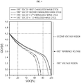
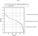
- FIGS. 6 and 7 are graphs related to a process in which the battery SOC estimation apparatus depicted in FIG. 1 sets the first reference voltage, the second reference voltage, the first voltage region and the second voltage region and estimates the first SOC and the second SOC as a SOC of the battery.
- the processor 130 may estimate the SOC of battery B in the first voltage region as the first SOC of the battery B and estimate the SOC of the battery B in the second voltage region as the second SOC of the battery B.
- the processor 130 may estimate the SOC of the battery B in the first voltage region as an initial SOC of the battery B, among the first SOC of the battery B calculated for each charge/discharge cycle through an charge/discharge experiment, namely the first SOC of the battery B calculated at the first charge/discharge cycle.
- the processor 130 may estimate the SOC of the battery B in the second voltage region as the second SOC of the battery B calculated in real time using the equivalent circuit model.
- the processor 130 may calculate a voltage change rate of the battery B changing corresponding to the second SOC of the battery B and set the second reference voltage based on the increase and decrease of the calculated voltage change rate.
- the processor 130 may calculate the voltage change rate of the battery B changing corresponding to the second SOC of the battery B and set the voltage of the battery B, at which the calculated voltage change rate is changed from a positive value to a negative value or from a negative value to a positive value, as the second reference voltage.
- the processor 130 may set the voltage "3.8V" of the battery B, at which the battery change rate of the battery B changes from a negative value to a positive value, as the second reference voltage.
- the processor 130 may set the first voltage region and the second voltage region using the first reference voltage and the second reference voltage. More specifically, the processor 130 may set a voltage region of the battery B equal to or lower than the first reference voltage as the first voltage region, set a voltage region higher than the first reference voltage as the second voltage region, and then further set a voltage region equal to or lower than the second reference voltage and higher than the first reference voltage as the first voltage region.
- the processor 130 may set a voltage region of the battery B equal to or lower than the first reference voltage "3.6V” as the first voltage region, set a voltage region of the battery B higher than the first reference "3.6V” voltage as the second voltage region, and then further set a voltage region equal to or lower than the second reference voltage "3.8V” and higher than the first reference voltage "3.6V” as the first voltage region.
- the processor 130 may estimate the SOC of the battery B in the first voltage region (0V to 3.8V) as an initial first SOC among the first SOCS of the battery B measured for each first charge/discharge cycle through the charge/discharge experiment, namely the first SOC of the battery B calculated at the first charge/discharge cycle.
- the processor 130 may estimate the SOC of the battery B in the second voltage region (higher than 3.8V) as the second SOC of the battery B calculated in real time using the equivalent circuit model.
- the battery SOC estimation apparatus 100 may estimate the SOC with a minimized error by using the characteristics of the first SOC having a small difference between the first SOCs for each charge/discharge cycle in a specific voltage region and the characteristics of the second SOC calculated nonlinearly in a specific voltage region.
- the battery SOC estimation apparatus 100 may estimate the SOC of the battery B in the first voltage region as the first SOC of the battery B by setting a voltage region, in which a difference between the first SOC calculated at the first charge/discharge cycle and the first SOC calculated at another charge/discharge cycle is insignificant among the first SOCs for every charge/discharge cycle, as the first voltage region.
- the battery SOC estimating apparatus 100 may estimate the SOC of the battery B in the second voltage region as the second SOC by setting a voltage region, which is linearly calculated, other than the voltage region where the second SOC is calculated nonlinearly, as the second voltage region.
Landscapes
- General Physics & Mathematics (AREA)
- Physics & Mathematics (AREA)
- Engineering & Computer Science (AREA)
- General Chemical & Material Sciences (AREA)
- Chemical & Material Sciences (AREA)
- Chemical Kinetics & Catalysis (AREA)
- Electrochemistry (AREA)
- Manufacturing & Machinery (AREA)
- Microelectronics & Electronic Packaging (AREA)
- Power Engineering (AREA)
- Secondary Cells (AREA)
- Charge And Discharge Circuits For Batteries Or The Like (AREA)
- Tests Of Electric Status Of Batteries (AREA)
Applications Claiming Priority (2)
| Application Number | Priority Date | Filing Date | Title |
|---|---|---|---|
| KR1020170136781A KR102239365B1 (ko) | 2017-10-20 | 2017-10-20 | 배터리 충전 상태 추정 장치 |
| PCT/KR2018/010005 WO2019078477A1 (fr) | 2017-10-20 | 2018-08-29 | Appareil et procédé d'estimation d'état de charge de batterie |
Publications (3)
| Publication Number | Publication Date |
|---|---|
| EP3637120A1 true EP3637120A1 (fr) | 2020-04-15 |
| EP3637120A4 EP3637120A4 (fr) | 2020-06-03 |
| EP3637120B1 EP3637120B1 (fr) | 2025-03-12 |
Family
ID=66174161
Family Applications (1)
| Application Number | Title | Priority Date | Filing Date |
|---|---|---|---|
| EP18867378.4A Active EP3637120B1 (fr) | 2017-10-20 | 2018-08-29 | Appareil et procédé d'estimation de l'état de charge (soc) d'une batterie |
Country Status (8)
| Country | Link |
|---|---|
| US (1) | US11480615B2 (fr) |
| EP (1) | EP3637120B1 (fr) |
| JP (1) | JP6907449B2 (fr) |
| KR (1) | KR102239365B1 (fr) |
| CN (1) | CN110651194B (fr) |
| ES (1) | ES3021212T3 (fr) |
| HU (1) | HUE070848T2 (fr) |
| WO (1) | WO2019078477A1 (fr) |
Families Citing this family (5)
| Publication number | Priority date | Publication date | Assignee | Title |
|---|---|---|---|---|
| KR102751977B1 (ko) * | 2020-07-10 | 2025-01-07 | 주식회사 엘지에너지솔루션 | 배터리 모니터링 장치 및 방법 |
| KR102869898B1 (ko) * | 2020-09-01 | 2025-10-14 | 삼성전자주식회사 | 배터리 상태 추정 방법 및 장치 |
| KR102875577B1 (ko) * | 2021-01-12 | 2025-10-22 | 주식회사 엘지에너지솔루션 | 배터리 관리 장치 및 방법 |
| JP7375786B2 (ja) * | 2021-03-26 | 2023-11-08 | トヨタ自動車株式会社 | 全固体リチウムイオン電池制御システム |
| CN113484762B (zh) * | 2021-07-16 | 2024-05-14 | 东风柳州汽车有限公司 | 电池健康状态估算方法、装置、设备及存储介质 |
Family Cites Families (31)
| Publication number | Priority date | Publication date | Assignee | Title |
|---|---|---|---|---|
| US7382110B2 (en) | 2004-04-23 | 2008-06-03 | Sony Corporation | Method of charging secondary battery, method of calculating remaining capacity rate of secondary battery, and battery pack |
| JP4086008B2 (ja) | 2004-04-28 | 2008-05-14 | ソニー株式会社 | 二次電池の残容量率算出方法および電池パック |
| SG120181A1 (en) * | 2004-08-18 | 2006-03-28 | Gp Batteries Internat Ltd | Method and system for determining the SOC of a rechargeable battery |
| JP5252875B2 (ja) | 2007-10-17 | 2013-07-31 | 株式会社マキタ | 園芸バリカンとそれに用いるブレードアセンブリ |
| KR100892821B1 (ko) | 2007-11-29 | 2009-04-10 | 현대자동차주식회사 | 배터리 충전상태 산출방법 |
| JP5158195B2 (ja) | 2008-06-06 | 2013-03-06 | 日本電気株式会社 | 回路設計システムおよび回路設計方法 |
| EP2351184A4 (fr) * | 2008-10-10 | 2014-07-09 | Deeya Energy Technologies Inc | Procédé et appareil permettant d établir l état de charge d une batterie |
| DE102009049589A1 (de) | 2009-10-16 | 2011-04-21 | Bayerische Motoren Werke Aktiengesellschaft | Verfahren zur Bestimmung und/oder Vorhersage der maximalen Leistungsfähigkeit einer Batterie |
| US9263773B2 (en) | 2010-01-19 | 2016-02-16 | Gs Yuasa International Ltd. | Secondary battery state of charge determination apparatus, and method of determining state of charge of secondary battery |
| CN102859381A (zh) * | 2010-04-22 | 2013-01-02 | 埃纳德尔公司 | 电池充电状态的监视 |
| JP5786324B2 (ja) | 2010-11-17 | 2015-09-30 | 日産自動車株式会社 | 組電池の制御装置 |
| JP5318128B2 (ja) * | 2011-01-18 | 2013-10-16 | カルソニックカンセイ株式会社 | バッテリの充電率推定装置 |
| JP5589909B2 (ja) | 2011-03-14 | 2014-09-17 | 株式会社リコー | 表示装置、表示装置のイベント切替え制御方法及びプログラム |
| KR101486470B1 (ko) * | 2012-03-16 | 2015-01-26 | 주식회사 엘지화학 | 배터리 상태 추정 장치 및 방법 |
| EP2899834B1 (fr) * | 2012-09-21 | 2021-02-24 | Nissan Motor Co., Ltd | Dispositif de calcul d'état de charge et procédé de calcul d'état de charge |
| US9846200B2 (en) | 2012-09-26 | 2017-12-19 | Sanyo Electric Co., Ltd. | Battery state estimation device and storage battery system |
| KR101983392B1 (ko) * | 2012-11-27 | 2019-05-29 | 에스케이이노베이션 주식회사 | 배터리 충전 상태 추정 장치 및 그 방법 |
| JP6155743B2 (ja) * | 2013-03-26 | 2017-07-05 | 株式会社Gsユアサ | 充電状態検出装置および充電状態検出方法 |
| JP6033155B2 (ja) | 2013-03-29 | 2016-11-30 | 日立オートモティブシステムズ株式会社 | 電池制御装置 |
| KR101708885B1 (ko) * | 2013-10-14 | 2017-02-21 | 주식회사 엘지화학 | 혼합 양극재를 포함하는 이차 전지의 상태 추정 장치 및 그 방법 |
| US10345386B2 (en) * | 2014-03-03 | 2019-07-09 | Panasonic Intellectual Property Management Co., Ltd. | Battery state estimation device and method of estimating battery state |
| KR102314211B1 (ko) | 2014-07-28 | 2021-10-19 | 현대모비스 주식회사 | 친환경차 배터리 관리 시스템의 배터리 잔존 용량 추정방법 |
| KR101655583B1 (ko) | 2014-11-26 | 2016-09-07 | 현대자동차주식회사 | 배터리 상태 추정 장치 및 방법 |
| JP6490414B2 (ja) * | 2014-12-05 | 2019-03-27 | 古河電気工業株式会社 | 二次電池状態検出装置および二次電池状態検出方法 |
| US10386418B2 (en) * | 2015-02-19 | 2019-08-20 | Mitsubishi Electric Corporation | Battery state estimation device |
| JP2016176780A (ja) | 2015-03-19 | 2016-10-06 | エスアイアイ・セミコンダクタ株式会社 | 電池残量予測装置及びバッテリパック |
| CN106324508B (zh) * | 2015-07-02 | 2020-06-02 | 华为技术有限公司 | 电池健康状态的检测装置及方法 |
| KR102032229B1 (ko) | 2015-11-18 | 2019-10-16 | 현대일렉트릭앤에너지시스템(주) | 배터리 수명 상태 추정 시스템 및 그 방법 |
| KR102574083B1 (ko) | 2016-01-12 | 2023-09-04 | 삼성전자주식회사 | 배터리 관리 장치 및 방법 |
| KR102040880B1 (ko) * | 2016-04-11 | 2019-11-05 | 주식회사 엘지화학 | 배터리 상태 추정 장치 및 방법 |
| KR20170136781A (ko) | 2016-06-02 | 2017-12-12 | 오경환 | 화학 첨가물을 함유하지 않는 천연 부추 소시지의 제조방법 |
-
2017
- 2017-10-20 KR KR1020170136781A patent/KR102239365B1/ko active Active
-
2018
- 2018-08-29 WO PCT/KR2018/010005 patent/WO2019078477A1/fr not_active Ceased
- 2018-08-29 US US16/610,204 patent/US11480615B2/en active Active
- 2018-08-29 CN CN201880031696.0A patent/CN110651194B/zh active Active
- 2018-08-29 HU HUE18867378A patent/HUE070848T2/hu unknown
- 2018-08-29 ES ES18867378T patent/ES3021212T3/es active Active
- 2018-08-29 EP EP18867378.4A patent/EP3637120B1/fr active Active
- 2018-08-29 JP JP2019561991A patent/JP6907449B2/ja active Active
Also Published As
| Publication number | Publication date |
|---|---|
| JP2021500528A (ja) | 2021-01-07 |
| ES3021212T3 (en) | 2025-05-26 |
| CN110651194A (zh) | 2020-01-03 |
| HUE070848T2 (hu) | 2025-07-28 |
| US11480615B2 (en) | 2022-10-25 |
| KR102239365B1 (ko) | 2021-04-09 |
| EP3637120B1 (fr) | 2025-03-12 |
| JP6907449B2 (ja) | 2021-07-21 |
| US20210190865A1 (en) | 2021-06-24 |
| CN110651194B (zh) | 2022-07-26 |
| EP3637120A4 (fr) | 2020-06-03 |
| WO2019078477A1 (fr) | 2019-04-25 |
| KR20190044398A (ko) | 2019-04-30 |
Similar Documents
| Publication | Publication Date | Title |
|---|---|---|
| US11372050B2 (en) | Apparatus and method for estimating state of charge of secondary battery | |
| US11150307B2 (en) | Apparatus and method for diagnosing battery | |
| KR101903225B1 (ko) | 이차 전지의 퇴화도 추정 장치 및 방법 | |
| US11391780B2 (en) | Battery diagnostic device and method | |
| EP3611525B1 (fr) | Dispositif d'estimation de la capacité libre d'une batterie | |
| EP3637120B1 (fr) | Appareil et procédé d'estimation de l'état de charge (soc) d'une batterie | |
| US20210156923A1 (en) | Apparatus and method for testing performance of battery cell | |
| US11422196B2 (en) | Device for estimating state of charge of battery | |
| EP3165934A1 (fr) | Appareil servant à estimer l'état de charge d'une batterie rechargeable et procédé associé | |
| US20210249885A1 (en) | Battery management device, battery management method, and battery pack | |
| EP4198536A1 (fr) | Appareil et procédé de gestion de batterie | |
| CN115398259B (zh) | 诊断电池状态的装置和方法 | |
| US20210167616A1 (en) | Battery management apparatus, battery management method and battery pack | |
| CN115516326A (zh) | 电池诊断设备和方法 | |
| US11581590B2 (en) | Apparatus and method for diagnosing insulation condition between battery pack and ground, and battery pack including the apparatus | |
| US11493557B2 (en) | Battery management apparatus, battery management method, and battery pack | |
| CN115667957B (zh) | 电池管理设备、电池检测装置及电池管理方法 | |
| US20260110752A1 (en) | Battery SOH Estimating Apparatus and Method | |
| KR102960363B1 (ko) | 배터리 soh 추정 장치 및 방법 | |
| EP4571336A1 (fr) | Appareil et procédé d'estimation de soh de batterie | |
| US20250327873A1 (en) | Apparatus and method for diagnosing battery |
Legal Events
| Date | Code | Title | Description |
|---|---|---|---|
| STAA | Information on the status of an ep patent application or granted ep patent |
Free format text: STATUS: THE INTERNATIONAL PUBLICATION HAS BEEN MADE |
|
| PUAI | Public reference made under article 153(3) epc to a published international application that has entered the european phase |
Free format text: ORIGINAL CODE: 0009012 |
|
| STAA | Information on the status of an ep patent application or granted ep patent |
Free format text: STATUS: REQUEST FOR EXAMINATION WAS MADE |
|
| 17P | Request for examination filed |
Effective date: 20191209 |
|
| AK | Designated contracting states |
Kind code of ref document: A1 Designated state(s): AL AT BE BG CH CY CZ DE DK EE ES FI FR GB GR HR HU IE IS IT LI LT LU LV MC MK MT NL NO PL PT RO RS SE SI SK SM TR |
|
| AX | Request for extension of the european patent |
Extension state: BA ME |
|
| A4 | Supplementary search report drawn up and despatched |
Effective date: 20200504 |
|
| RIC1 | Information provided on ipc code assigned before grant |
Ipc: H01M 10/48 20060101ALI20200427BHEP Ipc: G01R 31/36 20200101AFI20200427BHEP Ipc: G01R 31/382 20190101ALI20200427BHEP Ipc: H01M 10/42 20060101ALI20200427BHEP Ipc: G01R 31/3842 20190101ALI20200427BHEP |
|
| DAV | Request for validation of the european patent (deleted) | ||
| DAX | Request for extension of the european patent (deleted) | ||
| RAP1 | Party data changed (applicant data changed or rights of an application transferred) |
Owner name: LG ENERGY SOLUTION LTD. |
|
| RAP3 | Party data changed (applicant data changed or rights of an application transferred) |
Owner name: LG ENERGY SOLUTION, LTD. |
|
| STAA | Information on the status of an ep patent application or granted ep patent |
Free format text: STATUS: EXAMINATION IS IN PROGRESS |
|
| 17Q | First examination report despatched |
Effective date: 20221109 |
|
| GRAP | Despatch of communication of intention to grant a patent |
Free format text: ORIGINAL CODE: EPIDOSNIGR1 |
|
| STAA | Information on the status of an ep patent application or granted ep patent |
Free format text: STATUS: GRANT OF PATENT IS INTENDED |
|
| RIC1 | Information provided on ipc code assigned before grant |
Ipc: G01R 31/382 20190101ALI20240816BHEP Ipc: G01R 31/3842 20190101ALI20240816BHEP Ipc: H01M 50/569 20210101ALI20240816BHEP Ipc: H01M 10/48 20060101ALI20240816BHEP Ipc: H01M 10/42 20060101ALI20240816BHEP Ipc: G01R 31/36 20200101AFI20240816BHEP |
|
| INTG | Intention to grant announced |
Effective date: 20240830 |
|
| P01 | Opt-out of the competence of the unified patent court (upc) registered |
Free format text: CASE NUMBER: APP_49808/2024 Effective date: 20240903 |
|
| GRAJ | Information related to disapproval of communication of intention to grant by the applicant or resumption of examination proceedings by the epo deleted |
Free format text: ORIGINAL CODE: EPIDOSDIGR1 |
|
| STAA | Information on the status of an ep patent application or granted ep patent |
Free format text: STATUS: EXAMINATION IS IN PROGRESS |
|
| GRAP | Despatch of communication of intention to grant a patent |
Free format text: ORIGINAL CODE: EPIDOSNIGR1 |
|
| STAA | Information on the status of an ep patent application or granted ep patent |
Free format text: STATUS: GRANT OF PATENT IS INTENDED |
|
| INTC | Intention to grant announced (deleted) | ||
| INTG | Intention to grant announced |
Effective date: 20241216 |
|
| GRAS | Grant fee paid |
Free format text: ORIGINAL CODE: EPIDOSNIGR3 |
|
| GRAA | (expected) grant |
Free format text: ORIGINAL CODE: 0009210 |
|
| STAA | Information on the status of an ep patent application or granted ep patent |
Free format text: STATUS: THE PATENT HAS BEEN GRANTED |
|
| AK | Designated contracting states |
Kind code of ref document: B1 Designated state(s): AL AT BE BG CH CY CZ DE DK EE ES FI FR GB GR HR HU IE IS IT LI LT LU LV MC MK MT NL NO PL PT RO RS SE SI SK SM TR |
|
| REG | Reference to a national code |
Ref country code: GB Ref legal event code: FG4D |
|
| REG | Reference to a national code |
Ref country code: CH Ref legal event code: EP |
|
| REG | Reference to a national code |
Ref country code: DE Ref legal event code: R096 Ref document number: 602018080120 Country of ref document: DE |
|
| REG | Reference to a national code |
Ref country code: IE Ref legal event code: FG4D |
|
| REG | Reference to a national code |
Ref country code: ES Ref legal event code: FG2A Ref document number: 3021212 Country of ref document: ES Kind code of ref document: T3 Effective date: 20250526 |
|
| PG25 | Lapsed in a contracting state [announced via postgrant information from national office to epo] |
Ref country code: RS Free format text: LAPSE BECAUSE OF FAILURE TO SUBMIT A TRANSLATION OF THE DESCRIPTION OR TO PAY THE FEE WITHIN THE PRESCRIBED TIME-LIMIT Effective date: 20250612 |
|
| PG25 | Lapsed in a contracting state [announced via postgrant information from national office to epo] |
Ref country code: FI Free format text: LAPSE BECAUSE OF FAILURE TO SUBMIT A TRANSLATION OF THE DESCRIPTION OR TO PAY THE FEE WITHIN THE PRESCRIBED TIME-LIMIT Effective date: 20250312 |
|
| REG | Reference to a national code |
Ref country code: LT Ref legal event code: MG9D |
|
| PG25 | Lapsed in a contracting state [announced via postgrant information from national office to epo] |
Ref country code: NO Free format text: LAPSE BECAUSE OF FAILURE TO SUBMIT A TRANSLATION OF THE DESCRIPTION OR TO PAY THE FEE WITHIN THE PRESCRIBED TIME-LIMIT Effective date: 20250612 |
|
| PG25 | Lapsed in a contracting state [announced via postgrant information from national office to epo] |
Ref country code: HR Free format text: LAPSE BECAUSE OF FAILURE TO SUBMIT A TRANSLATION OF THE DESCRIPTION OR TO PAY THE FEE WITHIN THE PRESCRIBED TIME-LIMIT Effective date: 20250312 |
|
| REG | Reference to a national code |
Ref country code: NL Ref legal event code: MP Effective date: 20250312 |
|
| PG25 | Lapsed in a contracting state [announced via postgrant information from national office to epo] |
Ref country code: LV Free format text: LAPSE BECAUSE OF FAILURE TO SUBMIT A TRANSLATION OF THE DESCRIPTION OR TO PAY THE FEE WITHIN THE PRESCRIBED TIME-LIMIT Effective date: 20250312 |
|
| PG25 | Lapsed in a contracting state [announced via postgrant information from national office to epo] |
Ref country code: GR Free format text: LAPSE BECAUSE OF FAILURE TO SUBMIT A TRANSLATION OF THE DESCRIPTION OR TO PAY THE FEE WITHIN THE PRESCRIBED TIME-LIMIT Effective date: 20250613 Ref country code: BG Free format text: LAPSE BECAUSE OF FAILURE TO SUBMIT A TRANSLATION OF THE DESCRIPTION OR TO PAY THE FEE WITHIN THE PRESCRIBED TIME-LIMIT Effective date: 20250312 |
|
| REG | Reference to a national code |
Ref country code: HU Ref legal event code: AG4A Ref document number: E070848 Country of ref document: HU |
|
| REG | Reference to a national code |
Ref country code: AT Ref legal event code: MK05 Ref document number: 1775413 Country of ref document: AT Kind code of ref document: T Effective date: 20250312 |
|
| PG25 | Lapsed in a contracting state [announced via postgrant information from national office to epo] |
Ref country code: NL Free format text: LAPSE BECAUSE OF FAILURE TO SUBMIT A TRANSLATION OF THE DESCRIPTION OR TO PAY THE FEE WITHIN THE PRESCRIBED TIME-LIMIT Effective date: 20250312 |
|
| PG25 | Lapsed in a contracting state [announced via postgrant information from national office to epo] |
Ref country code: SE Free format text: LAPSE BECAUSE OF FAILURE TO SUBMIT A TRANSLATION OF THE DESCRIPTION OR TO PAY THE FEE WITHIN THE PRESCRIBED TIME-LIMIT Effective date: 20250312 |
|
| PGFP | Annual fee paid to national office [announced via postgrant information from national office to epo] |
Ref country code: HU Payment date: 20250827 Year of fee payment: 8 |
|
| PG25 | Lapsed in a contracting state [announced via postgrant information from national office to epo] |
Ref country code: SM Free format text: LAPSE BECAUSE OF FAILURE TO SUBMIT A TRANSLATION OF THE DESCRIPTION OR TO PAY THE FEE WITHIN THE PRESCRIBED TIME-LIMIT Effective date: 20250312 |
|
| PG25 | Lapsed in a contracting state [announced via postgrant information from national office to epo] |
Ref country code: PT Free format text: LAPSE BECAUSE OF FAILURE TO SUBMIT A TRANSLATION OF THE DESCRIPTION OR TO PAY THE FEE WITHIN THE PRESCRIBED TIME-LIMIT Effective date: 20250714 |
|
| PGFP | Annual fee paid to national office [announced via postgrant information from national office to epo] |
Ref country code: ES Payment date: 20250911 Year of fee payment: 8 |
|
| PGFP | Annual fee paid to national office [announced via postgrant information from national office to epo] |
Ref country code: DE Payment date: 20250721 Year of fee payment: 8 |
|
| PG25 | Lapsed in a contracting state [announced via postgrant information from national office to epo] |
Ref country code: PL Free format text: LAPSE BECAUSE OF FAILURE TO SUBMIT A TRANSLATION OF THE DESCRIPTION OR TO PAY THE FEE WITHIN THE PRESCRIBED TIME-LIMIT Effective date: 20250312 Ref country code: IT Free format text: LAPSE BECAUSE OF FAILURE TO SUBMIT A TRANSLATION OF THE DESCRIPTION OR TO PAY THE FEE WITHIN THE PRESCRIBED TIME-LIMIT Effective date: 20250312 |
|
| PGFP | Annual fee paid to national office [announced via postgrant information from national office to epo] |
Ref country code: BE Payment date: 20250722 Year of fee payment: 8 Ref country code: GB Payment date: 20250722 Year of fee payment: 8 |
|
| PG25 | Lapsed in a contracting state [announced via postgrant information from national office to epo] |
Ref country code: AT Free format text: LAPSE BECAUSE OF FAILURE TO SUBMIT A TRANSLATION OF THE DESCRIPTION OR TO PAY THE FEE WITHIN THE PRESCRIBED TIME-LIMIT Effective date: 20250312 |
|
| PGFP | Annual fee paid to national office [announced via postgrant information from national office to epo] |
Ref country code: FR Payment date: 20250725 Year of fee payment: 8 |
|
| PG25 | Lapsed in a contracting state [announced via postgrant information from national office to epo] |
Ref country code: EE Free format text: LAPSE BECAUSE OF FAILURE TO SUBMIT A TRANSLATION OF THE DESCRIPTION OR TO PAY THE FEE WITHIN THE PRESCRIBED TIME-LIMIT Effective date: 20250312 Ref country code: CZ Free format text: LAPSE BECAUSE OF FAILURE TO SUBMIT A TRANSLATION OF THE DESCRIPTION OR TO PAY THE FEE WITHIN THE PRESCRIBED TIME-LIMIT Effective date: 20250312 |
|
| PG25 | Lapsed in a contracting state [announced via postgrant information from national office to epo] |
Ref country code: RO Free format text: LAPSE BECAUSE OF FAILURE TO SUBMIT A TRANSLATION OF THE DESCRIPTION OR TO PAY THE FEE WITHIN THE PRESCRIBED TIME-LIMIT Effective date: 20250312 |
|
| PG25 | Lapsed in a contracting state [announced via postgrant information from national office to epo] |
Ref country code: SK Free format text: LAPSE BECAUSE OF FAILURE TO SUBMIT A TRANSLATION OF THE DESCRIPTION OR TO PAY THE FEE WITHIN THE PRESCRIBED TIME-LIMIT Effective date: 20250312 |
|
| PG25 | Lapsed in a contracting state [announced via postgrant information from national office to epo] |
Ref country code: IS Free format text: LAPSE BECAUSE OF FAILURE TO SUBMIT A TRANSLATION OF THE DESCRIPTION OR TO PAY THE FEE WITHIN THE PRESCRIBED TIME-LIMIT Effective date: 20250712 |
|
| REG | Reference to a national code |
Ref country code: DE Ref legal event code: R097 Ref document number: 602018080120 Country of ref document: DE |
|
| PG25 | Lapsed in a contracting state [announced via postgrant information from national office to epo] |
Ref country code: DK Free format text: LAPSE BECAUSE OF FAILURE TO SUBMIT A TRANSLATION OF THE DESCRIPTION OR TO PAY THE FEE WITHIN THE PRESCRIBED TIME-LIMIT Effective date: 20250312 |
|
| PLBE | No opposition filed within time limit |
Free format text: ORIGINAL CODE: 0009261 |
|
| STAA | Information on the status of an ep patent application or granted ep patent |
Free format text: STATUS: NO OPPOSITION FILED WITHIN TIME LIMIT |
|
| REG | Reference to a national code |
Ref country code: CH Ref legal event code: L10 Free format text: ST27 STATUS EVENT CODE: U-0-0-L10-L00 (AS PROVIDED BY THE NATIONAL OFFICE) Effective date: 20260121 |
|
| 26N | No opposition filed |
Effective date: 20251215 |
|
| REG | Reference to a national code |
Ref country code: CH Ref legal event code: H13 Free format text: ST27 STATUS EVENT CODE: U-0-0-H10-H13 (AS PROVIDED BY THE NATIONAL OFFICE) Effective date: 20260324 |
|
| PG25 | Lapsed in a contracting state [announced via postgrant information from national office to epo] |
Ref country code: MC Free format text: LAPSE BECAUSE OF FAILURE TO SUBMIT A TRANSLATION OF THE DESCRIPTION OR TO PAY THE FEE WITHIN THE PRESCRIBED TIME-LIMIT Effective date: 20250312 |
|
| PG25 | Lapsed in a contracting state [announced via postgrant information from national office to epo] |
Ref country code: LU Free format text: LAPSE BECAUSE OF NON-PAYMENT OF DUE FEES Effective date: 20250829 |
|
| PG25 | Lapsed in a contracting state [announced via postgrant information from national office to epo] |
Ref country code: CH Free format text: LAPSE BECAUSE OF NON-PAYMENT OF DUE FEES Effective date: 20250831 |