EP3637151A1 - Systèmes de dosimètre actifs pour des mesures de dose de rayonnement en temps réel - Google Patents
Systèmes de dosimètre actifs pour des mesures de dose de rayonnement en temps réel Download PDFInfo
- Publication number
- EP3637151A1 EP3637151A1 EP19197047.4A EP19197047A EP3637151A1 EP 3637151 A1 EP3637151 A1 EP 3637151A1 EP 19197047 A EP19197047 A EP 19197047A EP 3637151 A1 EP3637151 A1 EP 3637151A1
- Authority
- EP
- European Patent Office
- Prior art keywords
- user
- clause
- radiation
- ionizing radiation
- receiver
- Prior art date
- Legal status (The legal status is an assumption and is not a legal conclusion. Google has not performed a legal analysis and makes no representation as to the accuracy of the status listed.)
- Granted
Links
Images

Classifications
-
- G—PHYSICS
- G01—MEASURING; TESTING
- G01T—MEASUREMENT OF NUCLEAR OR X-RADIATION
- G01T1/00—Measuring X-radiation, gamma radiation, corpuscular radiation, or cosmic radiation
- G01T1/02—Dosimeters
-
- G—PHYSICS
- G01—MEASURING; TESTING
- G01T—MEASUREMENT OF NUCLEAR OR X-RADIATION
- G01T1/00—Measuring X-radiation, gamma radiation, corpuscular radiation, or cosmic radiation
- G01T1/02—Dosimeters
- G01T1/026—Semiconductor dose-rate meters
-
- G—PHYSICS
- G01—MEASURING; TESTING
- G01T—MEASUREMENT OF NUCLEAR OR X-RADIATION
- G01T7/00—Details of radiation-measuring instruments
Definitions
- the invention relates to active radiation dosimeters and methods for their use.
- Radiation dosimeters generally refer to devices that measure exposure to ionizing radiation and play vital role for workers in certain industries where there is routine radiation exposure. It is important for these workers to monitor the cumulative dose over time to ensure that their exposure does not exceed safe levels.
- the second class of dosimeter is referred to as an "active" dosimeter, which provides a communication reporting of the dose value to the user.
- active dosimeter typically include an alarm function that provides the user with an audible and/or visual indication that a threshold dose value has been reached.
- a personal dose equivalent As used herein generally refers to a quantity of ionizing radiation representing a safety threshold for exposure recommended by the International Commission on Radiation Units and Measurements (ICRU) for the dose equivalent in tissue at depth ( d ) below a specified point on the body.
- ICRU International Commission on Radiation Units and Measurements
- Examples of personal dose equivalents include a deep dose equivalent safety threshold value of about H p (10) (e.g. for thoracic exposure) and a surface dose equivalent safety threshold value of about H p (0.07) (e.g. for skin exposure).
- thermoluminescent dosimeters TLD
- integrating dosimeters Passive dosimetry devices, such as thermoluminescent dosimeters (TLD) or what are referred to as "integrating dosimeters", have been used to monitor extremity exposure to radiation.
- Some embodiments of integrating dosimeter may be able to communicate a reading to the user, however such devices do not provide real-time notification to users when they are receiving potentially damaging radiation exposure. Rather, embodiments of integrating dosimeter devices provide a one-time cumulative reading of exposure that occurs over an extended period of time, where the exposure reading is typically provided when it is too late to take action during the period of actual exposure to the ionizing radiation.
- True active dosimetry provides a significant benefit over passive dosimetry because users can be informed in "real-time" when they have entered a radiation field that poses a short or long term danger, and providing the users with the opportunity to remove themselves from harm's way.
- the term "real-time” as used herein typically refers to reporting, depicting, or reacting to events at the same rate and sometimes at the same time as they unfold, rather than delaying a report or action.
- a light and compact active dosimetry device that is comfortably wearable on or near the extremities, including fingers, hands, wrists, legs, ankles, feet, brain, uterus (e.g. for measuring fetal exposure), and eyes.
- An embodiment of an active dosimeter system for detecting and communicating a radiation dose in real time comprises a peripheral detector configured to be worn on an extremity or a head region of a user that includes a radiation sensor to detect ionizing radiation; a processor to determine a level of the ionizing radiation; and a wireless device to send a transmission comprising the detected level of the ionizing radiation; where the determination of the level of ionizing radiation and the transmission occur in real-time; and a receiver located in close proximity to the user that receives the transmission, and comprises an interface that informs the user of the detected level of the ionizing radiation.
- the peripheral detector communicates with the receiver which is itself a whole-body dosimeter or another piece of personal protective equipment (PPE) that comprises a user interface.
- Informing the user may comprise notification (visual, auditory, or tactile alerts related to specific thresholds), and may comprise quantification (visual, auditory, or tactile representation proportional to the detected level).
- embodiments of the described invention include an active dosimeter system configured as a peripheral detector wearable on the extremities or head region of a user that provides real-time communication to a receiver device located in close proximity to the user.
- some embodiments include a wearable peripheral detector that comprises a radiation sensor and a wear sensor configured to detect one more signals from the user indicating that the peripheral detector is being worn on the user's body.
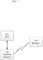
- Figure 1 provides a simplified illustrative example of peripheral detector 110 that is worn in close proximity to an extremity or head area by user 101.
- the extremity may be a finger, hand, wrist, arm, ankle, leg, or any other area of the body that might need to be separately monitored for radiation dose.
- the peripheral monitoring function might also be applied to supplemental fetal exposure monitoring for a declared pregnant worker.
- Figure 1 also illustrates receiver 130 that receives one or more wireless communications from peripheral detector 110 and provides user 101 with real-time information on radiation dose detected by peripheral detector 110 based on the communications received.
- receiver 130 is located in close proximity to user 101 and may include a device such as a piece of personal protective equipment (e.g.
- a whole-body dosimeter or another detector worn by user 101 that comprises a processor, data storage element and a user interface such as a display (e.g. graphical user interface (GUI) or other type of interface) and/or speaker interface for audible communication (e.g. an alert message or alarm).
- GUI graphical user interface
- the processor in the whole body dosimeter may combine the level of ionizing radiation detected by peripheral detector 110 with a level of ionizing radiation detected by the whole-body dosimeter.
- the combined levels of ionizing radiation from peripheral detector and whole-body dosimeter may be configured as multiple dose variables in a user's dose record that is stored in the whole-body dosimeter (at least for an interim period) and communicated to a centralized data repository.
- receiver 130 may include a smart phone, tablet, or other general purpose wireless-capable device. Further, receiver 130 may include a wearable device, such as a ring or bracelet that is specifically intended to provide notifications to the wearer. Such a wearable device may comprise an interface that informs the user of radiation events.
- the term "close proximity" as used herein in reference to the spatial relationship between receiver 130 and user 101 generally refers to a location within a range where user 101 can unambiguously identify a signal from receiver 130 and respond accordingly. For example, an acceptable range may depend on the type and/or intensity of signal or combination of signals provided by receiver 130 such as audible, visual, or mechanical (e.g. vibration) signals.
- some or all embodiments of receiver 130 may include a processor or microprocessor as well as data storage elements.
- peripheral detector 110 and/or receiver 130 may additionally provide electronic access control and/or tracking capabilities to allow and/or track when user 101 is at particular locations such as where security permissions are required.
- peripheral detector 110 and/or receiver 130 may include some form of what is referred to as Radio-frequency identification (RFID) or other suitable technology that is recognizable by security devices controlling access to locations where access is limited and/or is tracked.
- RFID Radio-frequency identification
- the RFID element in peripheral detector 110 and/or receiver 130 identifies user 101 to the security device, and if appropriate permissions have been granted will allow user 101 access to the location.
- peripheral detector 110 and/or receiver 130 can record data that identifies when user 101 is at the location.
- peripheral detector 110 and/or receiver 130 may be configured to engage with a central base station either while in use or when not in use by user 101.
- Embodiments of the central base station may provide charging capability for peripheral detector 110 and/or receiver 130 as well as a network connection that provides the capability for peripheral detector 110 and/or receiver 130 to transmit data (e.g. via a wireless or direct connection) to other computing devices via the network and/or receive information such as software updates, detection parameters, security identifiers, etc.
- a central base station may include a processor or microprocessor as well as data storage elements that may be particularly useful if a consistent network connection is not available.
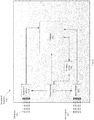
- Figure 2 provides an illustrative example of peripheral detector 110 that is physically compact and light weight so that it can be comfortably worn by user 101 for an extended period of time and allowing full freedom of movement.
- the physically compact nature enables peripheral detector 110 to be discreetly worn by user 101 and in some cases is not readily recognizable as a radiation dosimeter device.
- peripheral detector 110 is designed to be inconspicuous when worn by user 101 that enables use in covert applications.
- Embodiments of peripheral detector 110 may include a wearable design that comfortably fits in close proximity to an extremity or head region for which radiation measurement is desired.
- wearable design include designs such as rings, necklaces, pendants, bracelets, ear pieces, glasses, or other type of accessory wearable in close proximity to an extremity or head region.
- other examples of wearable design may include clothing designs such as gloves, hats, shoes, or other type of clothing design.
- housing or packaging elements of peripheral detector 110 may be constructed of any suitable lightweight material such as a rubber, natural fiber, plastic, polymer, metal, glass, or other suitable material or combinations of materials.
- embodiments of the described invention include radiation sensor 215 that generates signals proportional to a dose exposure of radiation 205 experienced at the extremity and/or head region of user 101.
- radiation 205 may include ionizing radiation such as X-rays, gamma-rays, beta particles and neutrons.
- wear sensor 225 that detects wear signal 207 and generates signals that indicates that peripheral detector 110 is being worn by user 101, and in some embodiments worn in the proper proximity to the extremity or head region for which radiation dose measurements are desired (e.g. to indicate that peripheral detector 110 is in use as a radiation sensor).
- wear signal 207 may include one or more biological criteria such as temperature (e.g.
- wear signal 207 may also include activity based signals detectable by elements such as an accelerometer (e.g. detect the motion of an extremity when worn by user 101) or pressure switch (e.g. detects pressure needed for user 101 to wear peripheral detector 110 such as with a bracelet).
- an accelerometer e.g. detect the motion of an extremity when worn by user 101
- pressure switch e.g. detects pressure needed for user 101 to wear peripheral detector 110 such as with a bracelet.
- wear signal 207 may also include accurate position-based information such as information that may include what is referred to as "received signal strength indication” (RSSI) technology.
- RSSI is a technology utilized in the telecommunications industry that typically includes a measurement of the power present in a received radio signal that may be expressed in decibels (dB) or decibels per milliwatt (dBm).
- the RSSI measurement make include a range from 0 (zero) to -120db and the closer it is to zero, the stronger the signal is.
- RSSI may be used to accurately identify the position of peripheral detector 110 relative to one or more other devices (e.g. that may include receiver 130) carried or worn by the user 101 using the measurements of the relative strength of wear signal 207.
- peripheral detector 110 may include a wearable glasses format using RSSI or gravitational acceleration to accurately identify that the glasses are being worn and positioned over the eyes of user 101 rather than pushed to the top of the head, hanging from a pocket, or some other position on the body of user 101 that is not the intended position for detection of ionizing radiation exposure.
- the strength of wear signal 207 from one or more other devices may be detected by wear sensor 225 and processed by processor 245 to identify the specific position of peripheral detector 110 on the body of user 101 based on the measured strength of wear signal 207 and a known correlation of detected strength and position on the body relative to the one or more devices emitting wear signal 207.
- peripheral detector 110 may include a variety of wearable formats and thus the presently described example should not be limiting.
- the signal emitted by wireless device 255 of peripheral detector 110 may be used by receiver 130 to compute the specific position on the body of user 101 using RSSI technology. For example, if the correlation between position of peripheral detector 110 on the body of user 101 and measured power detected by receiver 130 is known, then the specific position of peripheral detector 110 on the body of user 101 can be easily computed.
- peripheral detector 110 may limit the amount of power that can be stored in power source 210. Further, peripheral detector 110 may be required to operate over extended periods of time where very efficient power usage over time is advantageous. Therefore, it is highly desirable that all components of peripheral detector 110 consume as little power as possible during operation.
- processor 245 may include any type of suitable processor/microprocessor, controller/microcontroller, or other type information processing device known in the related art or combinations thereof. Also, embodiments of processor 245 may include any of a variety of known memory storage devices that may include one or more library files stored thereon. Further, the memory storage devices may have control logic (computer software program, including program code) stored therein that, when executed by processor 245, causes processor 245 to perform functions described herein.
- control logic computer software program, including program code
- embodiments of radiation sensor 215 typically comprise a detector 310, an amplifier 320, a signal processor 330, and one or more event counters 340.
- the detector 310 may include a semiconductor crystal, a PiN diode, a MOSFET (e.g. a metal-oxide-semiconductor field-effect transistor), a scintillating crystal with a photomultiplier, or other type of radiation sensor known in the relevant art.
- processor 245 includes some of these components such as the amplification and signal processor that converts analog signals corresponding to a degree of radiation 205 detected by radiation detector 310 to digital signals.
- the amplification and signal processor converts analog signals that correspond to wear signal 207 detected by wear sensor 225 to digital signals.
- some embodiments may also include one or more event counters 340 that record details from sensors 215 and/or 225 such as the number of detected radiation dose events and in some implementations whether the detected events occur when peripheral detector 110 is in close proximity to the extremity or head region of interest.
- processor 245 correlate data from radiation sensor 215 to data from wear sensor 225 to generate an accurate assessment of actual radiation exposure to user 101. Further, processor 245 may also correlate data from radiation sensor 215 and/or data from wear sensor 225 with data associated with security access as described above in order to correlate radiation exposure received by user 101 with specific locations. In some or all of the described embodiments processor 245 and/or a processing element of receiver 130 may integrate data received over a period of time for storage and later reporting (e.g. via receiver 130 or through the central base station to one or more computing devices as described above). For example, processor 245 may report the radiation exposure experienced by user 101 for an entire period that user 101 spends at a particular location.
- processor 245 may only include measurements from radiation sensor 215 captured during periods when wear sensor 225 indicates that peripheral detector 110 is being worn by user 101.
- processor 245 may only include measurements from radiation sensor 215 captured during periods when wear sensor 225 indicates that peripheral detector 110 is being worn by user 101.
- user 101 fails to wear the device during a shift where they might receive radiation exposure, it is possible to detect non-compliance both through the wear sensor 225 and the receiver 130, with the possibility to restrict access or use of the radiation source(s) to prevent unmonitored exposure.
- radiation sensor 215 may record a radiation exposure level that may be reportable based on safety criteria, the event may not be considered significant for the calculation of radiation exposure for user 101 if peripheral detector 110 was not being worn or not being worn correctly (e.g. not in the correct position on the body of user 101) at the time of radiation exposure.
- processor 245 may include one or more software elements that provide processing capabilities for the features described above as well as other features such as generating communication packets of information for transmission via wireless device 255.
- amplifier 320 and signal processor 330 may include one or more hardware elements and/or software elements or any combination of the two that provide the features described above.
- FIG. 2 further illustrates an embodiment of wireless device 255 that may include a radio element and wireless antenna.
- Wireless device 255 may communicate with receiver 130 via any wireless technology known to those of ordinary skill in the related art and may depend, at least in part, on various criteria.
- the criteria may include, but is not limited to, range of transmission, data security, power requirements, physical dimension of radio and/or antenna, 1-way or 2-way communication, or other criteria.
- direct device to device communication can be achieved using what is generally referred to as "Bluetooth" technology that has become a standard for exchanging data over short distances using short-wavelength UHF radio waves.
- wireless device 255 may communicate with receiver 130 via an intermediate.
- Some examples of communication intermediate using intermediate devices include what is referred to as Wi-Fi that communicates via wireless router devices and cellular based communications that utilize cellular communication points supported by a telecommunications provider.
- wireless device 255 may use a text based communication (also referred to as "short message service” (SMS)) with receiver 130 or other communication protocol known in the art.
- SMS short message service
- processor 245 and wireless device 255 have low power requirements.
- processor 245 may utilize what is referred to as “solid state” components that typically have low power utilization characteristics.
- wireless device 255 may utilize what is referred to as a "low power” or “ultra-low power” wireless transmitters known to those of ordinary skill in the related art.
- embodiments of the presently described invention include power source 210 that is compact and meets the power requirements of peripheral detector 110 for use over prolonged periods of time in various environmental conditions (e.g. hot, cold, etc.). Also in some embodiments power source 210 may be easily replaceable or alternatively may be permanently built into the structure of peripheral detector 110.
- power source 210 may include a rechargeable battery that uses a NiMH or Li-based chemistry.
- power source 210 may include a replaceable primary battery that may or may not be rechargeable such as standard alkaline batteries or what may be referred to as a "high value capacitor” or "electric double-layer capacitor".
- Power source 210 may also include a combination of these elements, such as a primary battery plus a capacitor, or a primary battery plus a rechargeable battery, or other combinations known to those of ordinary skill in the related art.
- peripheral detector 110 is in regular communication with receiver 130 to provide user 101 with real-time information on radiation exposure.
- regular communication refers to substantially constant communication or communication at short interval periods such as, for example, sending a communication at a period of about every 1 to 10 seconds.
- the regular communication only occurs while peripheral detector 110 is worn by user 101 (e.g. as detected by wear sensor 225).
- radiation sensor 215 and the communications via wireless device 255 may be placed in a standby mode or shut off completely to conserve power during periods when peripheral detector 110 is not being worn or carried by user 101.
Landscapes
- Physics & Mathematics (AREA)
- Health & Medical Sciences (AREA)
- Life Sciences & Earth Sciences (AREA)
- General Physics & Mathematics (AREA)
- High Energy & Nuclear Physics (AREA)
- Molecular Biology (AREA)
- Spectroscopy & Molecular Physics (AREA)
- Measurement Of Radiation (AREA)
Applications Claiming Priority (2)
| Application Number | Priority Date | Filing Date | Title |
|---|---|---|---|
| US201662301005P | 2016-02-29 | 2016-02-29 | |
| EP17157983.2A EP3220166B1 (fr) | 2016-02-29 | 2017-02-24 | Systèmes de dosimètre actifs pour l'enregistrement de dose en temps réel |
Related Parent Applications (2)
| Application Number | Title | Priority Date | Filing Date |
|---|---|---|---|
| EP17157983.2A Division EP3220166B1 (fr) | 2016-02-29 | 2017-02-24 | Systèmes de dosimètre actifs pour l'enregistrement de dose en temps réel |
| EP17157983.2A Division-Into EP3220166B1 (fr) | 2016-02-29 | 2017-02-24 | Systèmes de dosimètre actifs pour l'enregistrement de dose en temps réel |
Publications (2)
| Publication Number | Publication Date |
|---|---|
| EP3637151A1 true EP3637151A1 (fr) | 2020-04-15 |
| EP3637151B1 EP3637151B1 (fr) | 2025-12-10 |
Family
ID=58162494
Family Applications (2)
| Application Number | Title | Priority Date | Filing Date |
|---|---|---|---|
| EP19197047.4A Active EP3637151B1 (fr) | 2016-02-29 | 2017-02-24 | Systèmes de dosimètre actifs pour des mesures de dose de rayonnement en temps réel |
| EP17157983.2A Active EP3220166B1 (fr) | 2016-02-29 | 2017-02-24 | Systèmes de dosimètre actifs pour l'enregistrement de dose en temps réel |
Family Applications After (1)
| Application Number | Title | Priority Date | Filing Date |
|---|---|---|---|
| EP17157983.2A Active EP3220166B1 (fr) | 2016-02-29 | 2017-02-24 | Systèmes de dosimètre actifs pour l'enregistrement de dose en temps réel |
Country Status (3)
| Country | Link |
|---|---|
| US (1) | US10365378B2 (fr) |
| EP (2) | EP3637151B1 (fr) |
| CN (1) | CN107132566B (fr) |
Families Citing this family (6)
| Publication number | Priority date | Publication date | Assignee | Title |
|---|---|---|---|---|
| CN109839653B (zh) * | 2017-11-29 | 2023-06-23 | 中国辐射防护研究院 | 一种个人眼晶体剂量测量装置及测量方法 |
| CN112601983B (zh) * | 2018-08-21 | 2025-04-25 | 赛默飞世尔科学测量技术有限公司 | 用于在脉冲式辐射场中产生警报的电子剂量计 |
| EP3969940A1 (fr) | 2019-05-16 | 2022-03-23 | Friedrich-Alexander-Universität Erlangen-Nürnberg | Dispositif permettant de détecter une dose de rayonnement frappant un cristallin |
| US11977093B2 (en) | 2021-10-12 | 2024-05-07 | Thermo Scientific Portable Analytical Instruments Inc. | Personal radiation dosimeter and density meter system and methods of use |
| EP4481443A4 (fr) * | 2022-02-14 | 2026-01-21 | Chiyoda Technol Corp | Dosimètre électronique |
| CN119548121A (zh) * | 2024-10-23 | 2025-03-04 | 华中科技大学同济医学院附属同济医院 | 淋巴水肿居家监管方法及相关设备 |
Citations (8)
| Publication number | Priority date | Publication date | Assignee | Title |
|---|---|---|---|---|
| US5235318A (en) * | 1990-11-21 | 1993-08-10 | Merlin Gerin | Individual electronic dosimetry installation |
| JP2001281339A (ja) * | 2000-03-29 | 2001-10-10 | Toshiba Corp | 放射線管理システム |
| US20050230596A1 (en) * | 2004-04-15 | 2005-10-20 | Howell Thomas A | Radiation monitoring system |
| US20140312242A1 (en) * | 2012-06-01 | 2014-10-23 | Landauer, Inc. | System for Wireless, Motion and Position-Sensing, Integrating Radiation Sensor and Energy Harvester for Occupational and Environmental Dosimetry |
| WO2014191957A1 (fr) * | 2013-05-31 | 2014-12-04 | Landauer, Inc. | Algorithme pour détection de position et de mouvement sans fil intégrant un capteur de rayonnement pour dosimètrie environnementale et occupationnelle |
| JP2014235037A (ja) * | 2013-05-31 | 2014-12-15 | 株式会社日立製作所 | 放射線管理区域管理システム |
| CN105054507A (zh) * | 2015-08-25 | 2015-11-18 | 江苏超敏仪器有限公司 | 一种电离辐射实时检测手环及其与手机数据交互的方法 |
| KR101574076B1 (ko) * | 2015-05-19 | 2015-12-03 | 서울검사 주식회사 | 방사선 작업자의 안전 및 피폭 관리 시스템 |
Family Cites Families (19)
| Publication number | Priority date | Publication date | Assignee | Title |
|---|---|---|---|---|
| JPS6188175A (ja) * | 1984-09-17 | 1986-05-06 | Power Reactor & Nuclear Fuel Dev Corp | 放射線用局部被曝警報装置 |
| US5151600A (en) * | 1992-04-13 | 1992-09-29 | Reliant Laser Corporation | Noseshade for monitoring exposure to ultraviolet radiation |
| BRPI0414359A (pt) * | 2000-06-16 | 2006-11-14 | Bodymedia Inc | sistema para a monitoração e gerenciamento do peso corpóreo e demais condições psicológicas que abrangem um planejamento interativo e personalizado, intervenção e capacidade de formular relatórios |
| WO2003051016A1 (fr) * | 2001-12-11 | 2003-06-19 | Koninklijke Philips Electronics N.V. | Systeme d'emission d'informations supplementaires via un reseau |
| WO2005008286A2 (fr) * | 2003-07-12 | 2005-01-27 | Radiation Watch Limited | Detecteur de rayonnement ionisant |
| KR101320020B1 (ko) * | 2005-07-09 | 2013-10-29 | 삼성디스플레이 주식회사 | 액정 표시 장치 |
| JP2007139435A (ja) | 2005-11-15 | 2007-06-07 | Mitsubishi Electric Corp | 放射線モニタ |
| EP2186045A1 (fr) * | 2007-08-31 | 2010-05-19 | 3M Innovative Properties Company | Suivi de la conformité d'articles de protection personnelle |
| US7826222B2 (en) * | 2008-07-03 | 2010-11-02 | Juniper Networks, Inc. | Front-to-back cooling system for modular systems with orthogonal midplane configuration |
| JP5356273B2 (ja) * | 2010-02-05 | 2013-12-04 | シャープ株式会社 | 照明デバイスおよび該照明デバイスを備えた照明装置 |
| US20120268279A1 (en) | 2011-04-21 | 2012-10-25 | Charles Terrance Hatch | Methods and systems for use in monitoring radiation |
| US20130033700A1 (en) * | 2011-08-05 | 2013-02-07 | Abdelbasset Hallil | Radiation dosimeter with localization means and methods |
| CN202837555U (zh) | 2012-02-07 | 2013-03-27 | 北京瑞迪泰克技术有限公司 | 腕表式个人剂量仪 |
| US8822924B2 (en) | 2012-06-01 | 2014-09-02 | Landauer, Inc. | Wireless, motion and position-sensing, integrating radiation occupational and environmental dosimetry |
| US20140031224A1 (en) * | 2012-07-24 | 2014-01-30 | Dow Agrosciences Llc | Safened herbicidal compositions including 4-amino-3-chloro-5-fluoro-6-(4-chloro-2-fluoro-3-methoxyphenyl)pyridine-2-carboxylic acid or a derivative thereof for use in rice |
| CN102866414A (zh) * | 2012-08-28 | 2013-01-09 | 中核能源科技有限公司 | 基于无线网络的核电站实时个人核辐射剂量控制系统 |
| CN102901978A (zh) | 2012-09-17 | 2013-01-30 | 浙江核芯监测科技有限公司 | 辐射剂量监测器 |
| CN102966414B (zh) | 2012-11-21 | 2015-12-23 | 南阳防爆电气研究所有限公司 | 一种火星熄灭器 |
| US20160097868A1 (en) | 2014-10-02 | 2016-04-07 | Source Production & Equipment Co., Inc. | Radiation surveying |
-
2017
- 2017-02-13 US US15/430,867 patent/US10365378B2/en active Active
- 2017-02-24 EP EP19197047.4A patent/EP3637151B1/fr active Active
- 2017-02-24 EP EP17157983.2A patent/EP3220166B1/fr active Active
- 2017-02-27 CN CN201710108276.5A patent/CN107132566B/zh active Active
Patent Citations (8)
| Publication number | Priority date | Publication date | Assignee | Title |
|---|---|---|---|---|
| US5235318A (en) * | 1990-11-21 | 1993-08-10 | Merlin Gerin | Individual electronic dosimetry installation |
| JP2001281339A (ja) * | 2000-03-29 | 2001-10-10 | Toshiba Corp | 放射線管理システム |
| US20050230596A1 (en) * | 2004-04-15 | 2005-10-20 | Howell Thomas A | Radiation monitoring system |
| US20140312242A1 (en) * | 2012-06-01 | 2014-10-23 | Landauer, Inc. | System for Wireless, Motion and Position-Sensing, Integrating Radiation Sensor and Energy Harvester for Occupational and Environmental Dosimetry |
| WO2014191957A1 (fr) * | 2013-05-31 | 2014-12-04 | Landauer, Inc. | Algorithme pour détection de position et de mouvement sans fil intégrant un capteur de rayonnement pour dosimètrie environnementale et occupationnelle |
| JP2014235037A (ja) * | 2013-05-31 | 2014-12-15 | 株式会社日立製作所 | 放射線管理区域管理システム |
| KR101574076B1 (ko) * | 2015-05-19 | 2015-12-03 | 서울검사 주식회사 | 방사선 작업자의 안전 및 피폭 관리 시스템 |
| CN105054507A (zh) * | 2015-08-25 | 2015-11-18 | 江苏超敏仪器有限公司 | 一种电离辐射实时检测手环及其与手机数据交互的方法 |
Also Published As
| Publication number | Publication date |
|---|---|
| US20170248703A1 (en) | 2017-08-31 |
| US10365378B2 (en) | 2019-07-30 |
| EP3220166A2 (fr) | 2017-09-20 |
| CN107132566B (zh) | 2020-11-06 |
| EP3637151B1 (fr) | 2025-12-10 |
| EP3220166B1 (fr) | 2019-10-23 |
| CN107132566A (zh) | 2017-09-05 |
| EP3220166A3 (fr) | 2018-02-07 |
Similar Documents
| Publication | Publication Date | Title |
|---|---|---|
| US10365378B2 (en) | Active dosimeter systems for real-time radiation dose measurements | |
| US11954991B2 (en) | Impact detection | |
| US20180211345A1 (en) | Automated system and process for providing personal safety | |
| US20190180594A1 (en) | Integrated thermophysiological stress warning device | |
| JP2018531443A6 (ja) | 個人の安全を確保するためのシステムとプロセスの自動化 | |
| JP2003528287A (ja) | 静電荷警告装置 | |
| KR101920537B1 (ko) | 위급환자 발생 감지용 스마트밴드 시스템을 이용한 위급환자정보 제공방법 | |
| US20210375121A1 (en) | Safety monitoring system | |
| Kostopoulos et al. | F2D: a location aware fall detection system tested with real data from daily life of elderly people | |
| US11361175B2 (en) | Systems, methods, and apparatuses, for monitoring personal protection equipment compliance | |
| US10782420B2 (en) | Range-extended dosimeter | |
| JP7206369B2 (ja) | パルス放射線場における警報発生のための電子線量計 | |
| KR101844495B1 (ko) | 모션 센서값을 이용하여 착용자의 활동을 인식할 수 있도록 하는 개인용 방사능 선량계의 데이터 처리 방법 | |
| JP5313843B2 (ja) | 生体情報検出システム及び方法 | |
| KR20250154667A (ko) | 현장근로자 안전장치 시스템 | |
| GB2630096A (en) | Wearable and hub communication system | |
| GB2535984A (en) | Healthcare monitoring and alarm system |
Legal Events
| Date | Code | Title | Description |
|---|---|---|---|
| PUAI | Public reference made under article 153(3) epc to a published international application that has entered the european phase |
Free format text: ORIGINAL CODE: 0009012 |
|
| STAA | Information on the status of an ep patent application or granted ep patent |
Free format text: STATUS: THE APPLICATION HAS BEEN PUBLISHED |
|
| AC | Divisional application: reference to earlier application |
Ref document number: 3220166 Country of ref document: EP Kind code of ref document: P |
|
| AK | Designated contracting states |
Kind code of ref document: A1 Designated state(s): AL AT BE BG CH CY CZ DE DK EE ES FI FR GB GR HR HU IE IS IT LI LT LU LV MC MK MT NL NO PL PT RO RS SE SI SK SM TR |
|
| STAA | Information on the status of an ep patent application or granted ep patent |
Free format text: STATUS: REQUEST FOR EXAMINATION WAS MADE |
|
| 17P | Request for examination filed |
Effective date: 20201015 |
|
| RBV | Designated contracting states (corrected) |
Designated state(s): AL AT BE BG CH CY CZ DE DK EE ES FI FR GB GR HR HU IE IS IT LI LT LU LV MC MK MT NL NO PL PT RO RS SE SI SK SM TR |
|
| STAA | Information on the status of an ep patent application or granted ep patent |
Free format text: STATUS: EXAMINATION IS IN PROGRESS |
|
| 17Q | First examination report despatched |
Effective date: 20221209 |
|
| GRAP | Despatch of communication of intention to grant a patent |
Free format text: ORIGINAL CODE: EPIDOSNIGR1 |
|
| STAA | Information on the status of an ep patent application or granted ep patent |
Free format text: STATUS: GRANT OF PATENT IS INTENDED |
|
| INTG | Intention to grant announced |
Effective date: 20250701 |
|
| GRAS | Grant fee paid |
Free format text: ORIGINAL CODE: EPIDOSNIGR3 |
|
| GRAA | (expected) grant |
Free format text: ORIGINAL CODE: 0009210 |
|
| STAA | Information on the status of an ep patent application or granted ep patent |
Free format text: STATUS: THE PATENT HAS BEEN GRANTED |
|
| AC | Divisional application: reference to earlier application |
Ref document number: 3220166 Country of ref document: EP Kind code of ref document: P |
|
| AK | Designated contracting states |
Kind code of ref document: B1 Designated state(s): AL AT BE BG CH CY CZ DE DK EE ES FI FR GB GR HR HU IE IS IT LI LT LU LV MC MK MT NL NO PL PT RO RS SE SI SK SM TR |
|
| P01 | Opt-out of the competence of the unified patent court (upc) registered |
Free format text: CASE NUMBER: UPC_APP_0011949_3637151/2025 Effective date: 20251103 |
|
| REG | Reference to a national code |
Ref country code: CH Ref legal event code: F10 Free format text: ST27 STATUS EVENT CODE: U-0-0-F10-F00 (AS PROVIDED BY THE NATIONAL OFFICE) Effective date: 20251210 Ref country code: GB Ref legal event code: FG4D |
|
| RIN1 | Information on inventor provided before grant (corrected) |
Inventor name: NELSON, GREG HOLGER |
|
| REG | Reference to a national code |
Ref country code: DE Ref legal event code: R096 Ref document number: 602017093134 Country of ref document: DE |
|
| REG | Reference to a national code |
Ref country code: IE Ref legal event code: FG4D |
|
| PGFP | Annual fee paid to national office [announced via postgrant information from national office to epo] |
Ref country code: GB Payment date: 20260210 Year of fee payment: 10 |
|
| PG25 | Lapsed in a contracting state [announced via postgrant information from national office to epo] |
Ref country code: ES Free format text: LAPSE BECAUSE OF FAILURE TO SUBMIT A TRANSLATION OF THE DESCRIPTION OR TO PAY THE FEE WITHIN THE PRESCRIBED TIME-LIMIT Effective date: 20251210 |
|
| REG | Reference to a national code |
Ref country code: LT Ref legal event code: MG9D |
|
| PG25 | Lapsed in a contracting state [announced via postgrant information from national office to epo] |
Ref country code: NO Free format text: LAPSE BECAUSE OF FAILURE TO SUBMIT A TRANSLATION OF THE DESCRIPTION OR TO PAY THE FEE WITHIN THE PRESCRIBED TIME-LIMIT Effective date: 20260310 |
|
| PGFP | Annual fee paid to national office [announced via postgrant information from national office to epo] |
Ref country code: DE Payment date: 20260129 Year of fee payment: 10 |
|
| PG25 | Lapsed in a contracting state [announced via postgrant information from national office to epo] |
Ref country code: FI Free format text: LAPSE BECAUSE OF FAILURE TO SUBMIT A TRANSLATION OF THE DESCRIPTION OR TO PAY THE FEE WITHIN THE PRESCRIBED TIME-LIMIT Effective date: 20251210 Ref country code: HR Free format text: LAPSE BECAUSE OF FAILURE TO SUBMIT A TRANSLATION OF THE DESCRIPTION OR TO PAY THE FEE WITHIN THE PRESCRIBED TIME-LIMIT Effective date: 20251210 |
|
| REG | Reference to a national code |
Ref country code: NL Ref legal event code: MP Effective date: 20251210 |
|
| PG25 | Lapsed in a contracting state [announced via postgrant information from national office to epo] |
Ref country code: RS Free format text: LAPSE BECAUSE OF FAILURE TO SUBMIT A TRANSLATION OF THE DESCRIPTION OR TO PAY THE FEE WITHIN THE PRESCRIBED TIME-LIMIT Effective date: 20260310 |
|
| PGFP | Annual fee paid to national office [announced via postgrant information from national office to epo] |
Ref country code: FR Payment date: 20260209 Year of fee payment: 10 |
|
| PG25 | Lapsed in a contracting state [announced via postgrant information from national office to epo] |
Ref country code: LV Free format text: LAPSE BECAUSE OF FAILURE TO SUBMIT A TRANSLATION OF THE DESCRIPTION OR TO PAY THE FEE WITHIN THE PRESCRIBED TIME-LIMIT Effective date: 20251210 |