EP3637214A1 - Procédé de commande de véhicule aérien sans pilote et véhicule aérien sans pilote - Google Patents
Procédé de commande de véhicule aérien sans pilote et véhicule aérien sans pilote Download PDFInfo
- Publication number
- EP3637214A1 EP3637214A1 EP17935486.5A EP17935486A EP3637214A1 EP 3637214 A1 EP3637214 A1 EP 3637214A1 EP 17935486 A EP17935486 A EP 17935486A EP 3637214 A1 EP3637214 A1 EP 3637214A1
- Authority
- EP
- European Patent Office
- Prior art keywords
- height
- relative height
- uav
- estimated
- determining
- Prior art date
- Legal status (The legal status is an assumption and is not a legal conclusion. Google has not performed a legal analysis and makes no representation as to the accuracy of the status listed.)
- Withdrawn
Links
Images



Classifications
-
- G—PHYSICS
- G05—CONTROLLING; REGULATING
- G05D—SYSTEMS FOR CONTROLLING OR REGULATING NON-ELECTRIC VARIABLES
- G05D1/00—Control of position, course, altitude or attitude of land, water, air or space vehicles, e.g. using automatic pilots
- G05D1/04—Control of altitude or depth
- G05D1/06—Rate of change of altitude or depth
- G05D1/0607—Rate of change of altitude or depth specially adapted for aircraft
- G05D1/0646—Rate of change of altitude or depth specially adapted for aircraft to follow the profile of undulating ground
-
- G—PHYSICS
- G05—CONTROLLING; REGULATING
- G05D—SYSTEMS FOR CONTROLLING OR REGULATING NON-ELECTRIC VARIABLES
- G05D1/00—Control of position, course, altitude or attitude of land, water, air or space vehicles, e.g. using automatic pilots
- G05D1/08—Control of attitude, i.e. control of roll, pitch, or yaw
- G05D1/0808—Control of attitude, i.e. control of roll, pitch, or yaw specially adapted for aircraft
-
- G—PHYSICS
- G05—CONTROLLING; REGULATING
- G05D—SYSTEMS FOR CONTROLLING OR REGULATING NON-ELECTRIC VARIABLES
- G05D1/00—Control of position, course, altitude or attitude of land, water, air or space vehicles, e.g. using automatic pilots
- G05D1/10—Simultaneous control of position or course in three dimensions
- G05D1/101—Simultaneous control of position or course in three dimensions specially adapted for aircraft
-
- B—PERFORMING OPERATIONS; TRANSPORTING
- B64—AIRCRAFT; AVIATION; COSMONAUTICS
- B64U—UNMANNED AERIAL VEHICLES [UAV]; EQUIPMENT THEREFOR
- B64U10/00—Type of UAV
- B64U10/10—Rotorcrafts
- B64U10/13—Flying platforms
-
- G—PHYSICS
- G01—MEASURING; TESTING
- G01S—RADIO DIRECTION-FINDING; RADIO NAVIGATION; DETERMINING DISTANCE OR VELOCITY BY USE OF RADIO WAVES; LOCATING OR PRESENCE-DETECTING BY USE OF THE REFLECTION OR RERADIATION OF RADIO WAVES; ANALOGOUS ARRANGEMENTS USING OTHER WAVES
- G01S13/00—Systems using the reflection or reradiation of radio waves, e.g. radar systems; Analogous systems using reflection or reradiation of waves whose nature or wavelength is irrelevant or unspecified
- G01S13/87—Combinations of radar systems, e.g. primary radar and secondary radar
-
- G—PHYSICS
- G01—MEASURING; TESTING
- G01S—RADIO DIRECTION-FINDING; RADIO NAVIGATION; DETERMINING DISTANCE OR VELOCITY BY USE OF RADIO WAVES; LOCATING OR PRESENCE-DETECTING BY USE OF THE REFLECTION OR RERADIATION OF RADIO WAVES; ANALOGOUS ARRANGEMENTS USING OTHER WAVES
- G01S13/00—Systems using the reflection or reradiation of radio waves, e.g. radar systems; Analogous systems using reflection or reradiation of waves whose nature or wavelength is irrelevant or unspecified
- G01S13/88—Radar or analogous systems specially adapted for specific applications
- G01S13/93—Radar or analogous systems specially adapted for specific applications for anti-collision purposes
- G01S13/933—Radar or analogous systems specially adapted for specific applications for anti-collision purposes of aircraft or spacecraft
- G01S13/935—Radar or analogous systems specially adapted for specific applications for anti-collision purposes of aircraft or spacecraft for terrain-avoidance
-
- G—PHYSICS
- G05—CONTROLLING; REGULATING
- G05D—SYSTEMS FOR CONTROLLING OR REGULATING NON-ELECTRIC VARIABLES
- G05D1/00—Control of position, course, altitude or attitude of land, water, air or space vehicles, e.g. using automatic pilots
- G05D1/0011—Control of position, course, altitude or attitude of land, water, air or space vehicles, e.g. using automatic pilots associated with a remote control arrangement
- G05D1/0022—Control of position, course, altitude or attitude of land, water, air or space vehicles, e.g. using automatic pilots associated with a remote control arrangement characterised by the communication link
-
- G—PHYSICS
- G05—CONTROLLING; REGULATING
- G05D—SYSTEMS FOR CONTROLLING OR REGULATING NON-ELECTRIC VARIABLES
- G05D1/00—Control of position, course, altitude or attitude of land, water, air or space vehicles, e.g. using automatic pilots
- G05D1/04—Control of altitude or depth
- G05D1/042—Control of altitude or depth specially adapted for aircraft
-
- G—PHYSICS
- G05—CONTROLLING; REGULATING
- G05D—SYSTEMS FOR CONTROLLING OR REGULATING NON-ELECTRIC VARIABLES
- G05D1/00—Control of position, course, altitude or attitude of land, water, air or space vehicles, e.g. using automatic pilots
- G05D1/10—Simultaneous control of position or course in three dimensions
- G05D1/101—Simultaneous control of position or course in three dimensions specially adapted for aircraft
- G05D1/106—Change initiated in response to external conditions, e.g. avoidance of elevated terrain or of no-fly zones
-
- G—PHYSICS
- G08—SIGNALLING
- G08G—TRAFFIC CONTROL SYSTEMS
- G08G5/00—Traffic control systems for aircraft
- G08G5/20—Arrangements for acquiring, generating, sharing or displaying traffic information
- G08G5/21—Arrangements for acquiring, generating, sharing or displaying traffic information located onboard the aircraft
-
- G—PHYSICS
- G08—SIGNALLING
- G08G—TRAFFIC CONTROL SYSTEMS
- G08G5/00—Traffic control systems for aircraft
- G08G5/50—Navigation or guidance aids
- G08G5/53—Navigation or guidance aids for cruising
-
- G—PHYSICS
- G08—SIGNALLING
- G08G—TRAFFIC CONTROL SYSTEMS
- G08G5/00—Traffic control systems for aircraft
- G08G5/50—Navigation or guidance aids
- G08G5/55—Navigation or guidance aids for a single aircraft
-
- G—PHYSICS
- G08—SIGNALLING
- G08G—TRAFFIC CONTROL SYSTEMS
- G08G5/00—Traffic control systems for aircraft
- G08G5/70—Arrangements for monitoring traffic-related situations or conditions
- G08G5/74—Arrangements for monitoring traffic-related situations or conditions for monitoring terrain
-
- B—PERFORMING OPERATIONS; TRANSPORTING
- B64—AIRCRAFT; AVIATION; COSMONAUTICS
- B64U—UNMANNED AERIAL VEHICLES [UAV]; EQUIPMENT THEREFOR
- B64U2101/00—UAVs specially adapted for particular uses or applications
- B64U2101/40—UAVs specially adapted for particular uses or applications for agriculture or forestry operations
-
- G—PHYSICS
- G08—SIGNALLING
- G08G—TRAFFIC CONTROL SYSTEMS
- G08G5/00—Traffic control systems for aircraft
- G08G5/50—Navigation or guidance aids
- G08G5/57—Navigation or guidance aids for unmanned aircraft
Definitions
- the present disclosure relates to the field of flight technology and, more particularly, to a method for controlling an unmanned aerial vehicle and an unmanned aerial vehicle thereof.
- UAVs unmanned aerial vehicles
- UAVs may rely on radar to provide reliable ground height and other data, and maintain the distance from ground reflectors through the data processing and control by a flight controller.
- the radar of a UAV is usually mounted directly below the UAV to conveniently determine the relative distance between the UAV and the ground reflectors directly below it, so as to achieve a flight with a fixed height.
- a UAV is in the process of automatic height processing, if the flight speed is slow or the terrain is relatively flat, the terrain following function may complete well.
- the height cannot be controlled in real time according to the relative distance measured by the radar. This causes the fixed height effects to always lag behind, and thus the terrain following function cannot complete well.
- the present disclosure provides a method for controlling a UAV and a UAV thereof, which is applied to solve the problem in the existing technologies that, when the flying speed is too fast or the terrain is quite undulating, it cannot be ensured that a UAV can complete the terrain following function well.
- the present disclosure provides a method for controlling a UAV.
- the method includes:
- the present disclosure provides a UAV.
- the UAV includes a controller.
- the controller is configured to:
- a combined relative height for reflecting a front terrain change is determined according to at least the first relative height and the second relative height.
- the flight attitude of the UAV is then controlled according to the combined relative height, thereby accomplishing the control of the flight attitude of the UAV according to the combined relative height reflecting the front terrain change. This then allows the UAV to be able to complete the terrain following function well, even if the flight speed is too fast or the terrain is quite undulating.
- the present disclosure is applied to a UAV, which may implement an automatic fixed height adjustment to solve the problem in the existing technologies, that is, when the flying speed is too fast or the terrain is quite undulating, because the propulsion system has a hysteresis effect, the fixed height effects always lag behind, and thus the terrain following function cannot complete well.
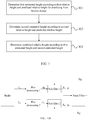
- FIG. 1 is a flowchart of a method for controlling an unmanned aerial vehicle according to one embodiment of the present disclosure.
- the execution entity of the disclosed embodiments may be a controller of a UAV.
- the method in the disclosed embodiment may include:
- Step 101 Determine a first relative height between a UAV and a ground reflector directly below the UAV and a second relative height between the UAV and a ground reflector ahead the UAV.
- the UAV may detect the first relative height and the second relative height by a radar mounted on the UAV. It is to be understood that the UAV may also use other devices, such as an ultrasonic detector or a laser radar, to achieve the goal of detecting the relative heights, which are not limited herein.
- the radar may specifically refer to a radar whose antenna is a directional antenna, or may refer to a radar whose antenna is a rotating antenna (i.e., a rotating radar). If the radar specifically refers to a radar whose antenna is a directional antenna, the disclosed radar may include a first radar and a second radar. The first radar vertically emits a radar wave downward, and the first relative height may be determined through the first radar.
- the second radar tilts forward and downward to emit a radar wave, and the second relative height may be determined by the second radar. If the disclosed radar specifically refers to a rotating radar whose antenna is a rotating antenna, when the rotating radar vertically emits a radar wave downward, the first relative height may be determined by the rotating radar. When the rotating radar tilts forward and downward to emit a radar wave, the second relative height may be determined by the rotating radar.
- the first radar may be mounted under the rack of an agricultural UAV or under the load of the rack.
- the second radar may be mounted on the rack of the UAV or the load of the rack in a tilted manner relative to the heading axis of the UAV. Specifically, when a UAV is flying forward, the second radar may be specifically mounted obliquely on the front of the rack or the load. When a UAV is flying backward, the second radar may be specifically mounted obliquely on the back of the rack or the load.
- the rotating radar may be mounted under the rack of an agricultural UAV or under the load of the rack, where the load of the rack may be, for example, a water tank.
- Step 101 may specifically include: acquiring a first distance between the UAV and a ground reflector directly below the UAV, and determining the first distance as the first relative height; acquiring, by using the radar on the UAV, a second distance between the UAV and a ground reflector ahead the UAV, and determining the second relative height according to the second distance.
- determining the second relative height according to the second distance may specifically include determining the second relative height according to the second distance and the angle of the emission direction of the radar wave emitted obliquely and downward by the radar with respect to the horizontal direction. As shown in FIG.
- A represents a UAV
- B represents the ground reflector ahead the UAV A
- L represents the distance, between the UAV A and the ground reflector B ahead the UAV A, measured by the radar
- ⁇ represents the angle of the emission direction of the radar wave, emitted obliquely and downward by the radar, with respect to the horizontal direction.
- H 2 L ⁇ sin ⁇ ⁇
- the aforementioned radar on a UAV may be understood as a radar that is a part of the UAV or as a radar mounted on the UAV.
- Step 102 Determine, according to at least the first relative height and the second relative height, a combined relative height for reflecting a front terrain change.
- the combined relative height may reflect a front terrain change other than the terrain directly below the UAV.
- the present disclosure does not limit the specific implementations for determining the combined relative height reflecting the front terrain change based on at least the first relative height and the second relative height. Any implementations for determining the combined relative height of the first relative height and the second relative height based on the first relative height and the second relative height shall fall within the protection scope of the present disclosure.
- the combined relative height may be determined based on the first relative height and the second relative height by using a weighted summation method.
- Step 103 Control a flight attitude of the UAV according to the combined relative height.
- the flight attitude may include dive, climb, acceleration, deceleration, and the like.
- controlling the flight attitude of a UAV according to the combined relative height may allow the UAV to be able to perform a predictive terrain following function.
- the flight attitude when the combined relative height is relatively large, the flight attitude may be a dive; when the combined relative height is small, the flight attitude may be a climb.
- the flight attitude when the combined relative height is relatively large and the difference between the combined relative height and the first relative height is large, the flight attitude may be a dive and acceleration.
- the flight attitude may be a climb and acceleration.
- the flight attitude may be a climb and deceleration.
- the above specific implementations for controlling the flight attitude of a UAV are only for illustrative purposes. Any specific implementation that controls the flight attitude of a UAV according to the combined relative height to allow the UAV to achieve the terrain following function shall fall within the protection scope of the present disclosure.
- a first relative height between a UAV and a ground reflector directly below the UAV and a second relative height between the UAV and a ground reflector ahead the UAV are determined.
- a combined relative height reflecting a front terrain change is determined based on at least the first relative height and the second relative height.
- a flight attitude of the UAV is then controlled according to the combined relative height. In this way, the flight attitude of a UAV is controlled according to the combined relative height reflecting the front terrain change. This allows the UAV to be able to complete the terrain following function well, when the flying speed is too fast or the terrain is quite undulating.
- FIG. 3 is a flowchart of a method for controlling a UAV according to another embodiment of the present disclosure.
- the present embodiment mainly describes, based on the embodiments shown in FIG. 1 , a specific implementation for determining a combined relative height reflecting the front terrain change based on at least the first relative height and the second relative height.
- the method in the disclosed embodiments may include:
- Step 301 Determine a first estimated height according to the first relative height and a predicted relative height for predicting a front terrain change.
- the predicted relative height may be a relative height predicted by any method for reflecting the front terrain change.
- the predicted relative height may be determined according to the combined relative height of a previous moment, where the combined relative height of the previous moment may be one combined relative height of a previous moment, or a plurality of combined relative heights of previous moments.
- the predicted relative height may be the combined relative height of the previous moment.
- the predicted relative height may be determined by averaging, weighted averaging, or other similar processing of the plurality of combined relative heights.
- Step 301 may specifically include: using a Kalman filtering algorithm to determining the first estimated height according to the first relative height and the predicted relative height.
- the first relative height is used as a measured value in the Kalman filtering algorithm
- the predicted relative height is used as a predicted value in the Kalman filtering algorithm
- the estimated value calculated by the Kalman filtering algorithm is the first estimated height.
- Step 302 Determine a second estimated height according to the second relative height and the predicted relative height.
- the second estimated height is specifically determined, according to the second relative height and the predicted relative height, by using a Kalman filtering algorithm. It should be noted that Step 302 is similar to Step 301, details of which will not be further described herein.
- Step 303 Determine the combined relative height according to the first estimated height and the second estimated height.
- Step 303 may specifically include: determining the combined relative height according to the first estimated height, a first weight corresponding to the first estimated height, the second estimated height, and a second weight corresponding to the second estimated height.
- the combined relative height may be determined according to the first estimated height, the first weight, the second estimated height, and the second weight by using a weighted summation or a weighted averaging method.
- the first weight and the second weight may be predefined or may be dynamically determined, and the present disclosure is not limited thereto.
- the first weight and the second weight may be dynamically determined as follows: determining a first innovation according to the first estimated height and the first relative height; determining a second innovation according to the second estimated height and the second relative height; determining, the first weight and the second weight according to the first innovation and the second innovation, where the larger the first innovation is, the smaller the first weight is and the larger the second weight is, the larger the second innovation is, the larger the first weight is and the smaller the second weight is.
- the sum of the first weight and the second weight may equal to 1.
- the first innovation may refer to a difference between the first estimated height and the first relative height
- the second innovation may refer to a difference between the second estimated height and the second relative height.
- the present disclosure does not limit the specific implementations for determining the first weight and the second weight according to the first innovation and the second innovation. Any specific implementations that satisfy the conditions for determining "the larger the first innovation is, the smaller the first weight is and the larger the second weight is, the larger the second innovation is, the larger the first weight is and the smaller the second weight is" shall fall within the protection scope of the present disclosure.
- the first weight w 1 may be determined by the following Formula (2)
- the second weight w 2 may be determined by the following Formula (3).
- w 1 g 1 ⁇ 1 ⁇ g 1 ⁇ 1 + g 2 ⁇ 1
- w 2 g 2 ⁇ 1 ⁇ g 1 ⁇ 1 + g 2 ⁇ 1
- the combined relative height X g may be determined according to the first estimated height X 1 , the first weight w 1 , the second estimated height X 2 , and the second weight w 2 by using the following Formula (4).
- X g w 1 ⁇ X 1 + w 2 ⁇ X 2
- a method for controlling a UAV in the present disclosure may be, for example, as shown in FIG. 4A .
- L 1 represents the first distance
- L 2 represents the second distance
- pre-processing 1 is used to determine the first relative height H 1 according to the first distance
- pre-processing 2 is used to determine the second relative height H 2 according to the second distance L 2
- sub-filter 1 is used to determine the first estimated height X 1 and the first innovation g 1 according to the first relative height H 1 and the combined relative height X g of a previous moment
- the sub-filter 2 is used to determine the second estimated height X 2 and the second innovation g 2 according to the second relative height H 2 and the combined relative height X g of the previous moment
- the main filter is used to determine the combined relative height X g according to the first estimated height X 1 , the second estimated height X 2 , the first innovation g 1 , and the second innovation g 2 .
- the relationship between the first relative height, the second relative height, and the combined relative height may be as shown in FIG. 4B .
- the changing trend of the combined relative height determined based on the first relative height and the second relative height may optimally reflect the front terrain change (i.e., the change of the second relative height) and also reflect the trend of the terrain below (i.e., the trend of the first relative height). This will help prevent instable flights due to the abrupt changes.
- the first estimated height is determined according to the first relative height and the predicted relative height for predicting the front terrain change
- the second estimated height is determined according to the second relative height and the predicted relative height.
- the combined relative height is determined according to the first estimated height and the second estimated height. This then allows the combined relative height to be determined according to the first relative height and the second relative height.
- FIG. 5 is a flowchart of a method for controlling a UAV according to yet another embodiment of the present disclosure. Based on the embodiment shown in FIG. 1 , this embodiment mainly describes an optional implementation for determining the combined relative height for reflecting the front terrain change based on at least the first relative height and the second relative height. As shown in FIG. 5 , the method in the disclosed embodiments may include:
- Step 501 Determine a first relative height between the UAV and a ground reflector directly below the UAV, a second relative height between the UAV and a ground reflector ahead the UAV, and a third relative height between the UAV and a ground reflector behind the UAV.
- the UAV may detect the first relative height, the second relative height, and the third relative height.
- the radar may specifically refer to a radar whose antenna is a directional antenna, or a rotating radar whose antenna is a rotating antenna. If the radar specifically refers to a radar whose antenna is a directional antenna, the radar may include a first radar, a second radar, and a third radar.
- the first radar vertically emits a radar wave downward, through which the first relative height may be determined.
- the second radar tilts forward and downward to emit a radar wave, through which the second relative height may be determined.
- the third radar tilts backward and downward to emit a radar wave, through which the third relative height between the UAV and a ground reflector behind the UAV may be determined.
- the radar is specifically a rotating radar
- the rotating radar when the rotating radar vertically emits a radar wave downward, the first relative height may be determined through the rotating radar.
- the rotating radar tilts forward and downward to emit a radar wave the second relative height may be determined through the rotating radar.
- the third relative height may be determined through the rotating radar.
- the first radar may be mounted under the rack of an agricultural UAV or under the load of the rack.
- the second radar and the third radar may be mounted on the rack of the UAV or on the load of the rack in obliquely relative to the heading axis of the UAV.
- the second radar when the UAV is flying forward, the second radar may be specifically mounted obliquely on the front of the rack or the load, and the third radar may be specifically mounted obliquely on the back of the rack or the load.
- the second radar When the UAV is flying backward, the second radar may be specifically mounted obliquely on the back of the rack or the load, and the third radar may be obliquely mounted on the front of the rack or the load.
- the rotating radar may be mounted under the rack of the agricultural UAV or under the load of the rack.
- the load of the rack may be, for example, a water tank.
- the rotating radar may be mounted under the rack of the UAV or on the stand of the UAV.
- Step 501 may specifically include: acquiring, by using the radar on the UAV, a first distance between the UAV and a ground reflector directly below the UAV, and determining the first distance as the first relative height; acquiring, by using the radar on the UAV, a second distance between the UAV and a ground reflector ahead the UAV, and determining the second relative height according to the second distance; acquiring, by the radar on the UAV, a third distance between the UAV and a ground reflector behind the UAV, and determining the third relative height according to the third distance.
- the specific ways for determining the third relative height according to the third distance are similar to the specific ways of determining the second relative height according to the second distance shown in FIG. 2 , details of which are not described herein again.
- the foregoing radar on a UAV can be a radar as a part of the UAV, or a radar that is mounted on the UAV.
- Step 502 Determine the combined relative height according to the first relative height, the second relative height, and the third relative height.
- the third relative height between a UAV and the ground reflector behind the UAV may also be considered. Even for a scene with a sudden change in terrain, the accuracy of determining the combined relative height with the consideration of the third relative height may be ensured by adjusting the importance of the third relative height in determining the combined relative height. For example, for a scene with sudden changes in terrain, the third relative height is less important in determining the combined relative height. For a scene without sudden changes in terrain, the third relative height is more important in determining the combined relative height.
- the present disclosure does not limit the specific implementations for determining the combined relative height reflecting the front terrain change according to the first relative height, the second relative height, and the third relative height. Any implementations for determining the combined relative height of the first relative height, the second relative height, and the third relative height according to the first relative height, the second relative height, and the third relative height are within the protection scope of the present disclosure.
- the combined relative height may be determined according to the first relative height, the second relative height, and the third relative height by using a weighted summation method.
- Step 502 may specifically include: determining a first estimated height according to the first relative height and the predicted relative height for predicting a front terrain change; determining a second estimated height according to the second relative height and the predicted relative height; determining a third estimated height according to the third relative height and the predicted relative height; and determining the combined relative height according to the first estimated height, the second estimated height, and the third estimated height.
- the present disclosure does not limit the specific implementations for determining the combined relative height according to the first estimated height, the second estimated height, and the third estimated height.
- an average of the first estimated height, the second estimated height, and the third estimated height may be as the combined relative height.
- the combined relative height may be specifically determined based on the first estimated height, a first weight corresponding to the first estimated height, the second estimated height, a second weight corresponding to the second estimated height, the third estimated height and a third weight corresponding to the third estimated height.
- a weighted summation or a weighted averaging may be used to determine the combined relative height according to the first estimated height, the first weight, the second estimated height, the second weight, the third estimated height, and the third weight.
- the first weight, the second weight, and the third weight may be predefined or may be dynamically determined, and the present disclosure is not limited thereto.
- the first weight, the second weight, and the third weight may be dynamically determined as follows: determining a first innovation according to the first estimated height and the first relative height; determining a second innovation according to the second estimated height and the second relative height; determining a third innovation according to the third estimated height and the third relative height; determining the first weight, the second weight, and the third weight according to the first innovation, the second innovation, and the third innovation; where the larger the first innovation is, the smaller the first weight is and the larger the sum of the second weight and the third weight is, the larger the second innovation is, the smaller the second weight is and the larger the sum of the first weight and the third weight is, and the larger the third innovation is, the smaller the third weight is and the larger the sum of the first weight and the second weight is.
- the sum of the first weight, the second weight, and the third weight may equal to 1.
- the present disclosure does not limit the specific implementations for determining the first weight, the second weight, and the third weight according to the first innovation, the second innovation, and the third innovation. Any specific implementations that satisfy the conditions for determining "the larger the first innovation is, the smaller the first weight is and the larger the sum of the second weight and the third weight is, the larger the second innovation is, the smaller the second weight is and the larger the sum of the first weight and the third weight is, and the larger the third innovation is, the smaller the third weight is and the larger the sum of the first weight and the second weight is" shall fall within the protection scope of the present disclosure.
- the first weight w 1 may be determined according to the following Formula (5)
- the second weight w 2 may be determined according to the following Formula (6)
- the third weight w 3 may be determined according to the following Formula (7).
- w 1 g 1 ⁇ 1 ⁇ g 1 ⁇ 1 + g 2 ⁇ 1 + g 3 ⁇ 1
- w 2 g 2 ⁇ 1 ⁇ g 1 ⁇ 1 + g 2 ⁇ 1 + g 3 ⁇ 1
- w 3 g 3 ⁇ 1 ⁇ g 1 ⁇ 1 + g 2 ⁇ 1 + g 3 ⁇ 1
- the combined relative height X g may be determined according to the first estimated height X 1 , the first weight w 1 , the second estimated height X 2 , the second weight w 2 , the third estimated height X 3 , and the third weight w 3 by using the following Formula (8).
- X g w 1 ⁇ X 1 + w 2 ⁇ X 2 + w 3 ⁇ X 3
- a UAV control method of the present disclosure may be, for example, as shown in FIG. 6 .
- L 1 represents the first distance
- L 2 represents the second distance
- L 3 represents the third distance
- the pre-processing 1 is used to determine the first relative height H 1 according to the first distance
- the pre-processing 2 is used to determine the second relative height H 2 according to the second distance L 2
- the pre-processing 3 is to determine the third relative height H 3 according to the third distance L 3
- the sub-filter 1 is for determining the first estimated height X 1 and the first innovation g 1 according to the first relative height H 1 and the combined relative height X g of a previous moment
- the sub-filter 2 is for determining the second estimated height X 2 and the second innovation g 2 according to the second relative height H 2 and the combined relative height X g of the previous moment
- the sub-filter 3 is for determining the third estimated height X 3 and the third innovation g 3 according to the third relative height H 3 and the combined relative height X
- Step 503 Control a flight attitude of the UAV according to the combined relative height.
- Step 503 is similar to Step 103, details of which are not described herein again.
- the first relative height between the UAV and the ground reflector directly below the UAV, the second relative height between the UAV and the ground reflector ahead the UAV, and the third relative height between the UAV and the ground reflector behind the UAV are determined.
- the combined relative height for reflecting the front terrain change is determined, and the flight attitude of the UAV is controlled according to the combined relative height.
- the flight attitude of the UAV may be controlled according to the combined relative height reflecting the front terrain change. This allows the UAV to perform the terrain following function well when the flying speed is too fast or the terrain is quite undulating.
- the tilt angle of the obliquely emitted radar wave may be dynamically adjusted according to the time delay of the propulsion system hysteresis effect.
- the method may further include: determining a tilt angle of the radar wave according to the time delay of the propulsion system hysteresis effect of the UAV; and adjusting the emission direction of the radar wave according to the tilt angle.
- the time delay of the propulsion system hysteresis effect when the time delay of the propulsion system hysteresis effect is long, it may indicate that the propulsion system reacts slowly. In order to ensure sufficient reaction time for the propulsion system, it is necessary to know the terrain change of a far distance range ahead.
- the time delay of the propulsion system hysteresis effect When the time delay of the propulsion system hysteresis effect is short, it may indicate that the propulsion system reacts quickly and the reaction time reserved for the propulsion system may be short, and thus it is only necessary to know the terrain change of a short distance range ahead. Therefore, when the tilt angle of a radar wave is an angle of the emission direction of the radar wave with respect to the horizontal direction, the relationship between the time delay and the tilt angle may be specifically: the longer the time delay is, the smaller the tilt angle is; and the shorter the time delay is, the larger the tilt angle is.
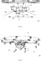
- FIG. 7 is a schematic diagram of a UAV according to one embodiment of the present disclosure.
- FIG. 8 is a schematic structural diagram of a UAV according to one embodiment of the present disclosure.
- FIG. 9 is a schematic structural diagram of a UAV according to another embodiment of the present disclosure.
- the UAV 700 of the disclosed embodiments may include: a controller 707, which is configured to:
- determining, by the controller 701, the combined relative height for reflecting the front terrain change according to at least the first relative height and the second relative height specifically includes:
- determining, by the controller 701, the combined relative height according to at least the first estimated height and the second estimated height specifically includes: determining the combined relative height according to the first estimated height, a first weight corresponding to the first estimated height, the second estimated height, and a second weight corresponding to the second estimated height.
- determining, by the controller 701, the combined relative height according to the first estimated height, the first weight corresponding to the first estimated height, the second estimated height, and the second weight corresponding to the second estimated height specifically includes: using a weighted summation method to determine the combined relative height according to the first estimated height, the first weight corresponding to the first estimated height, the second estimated height, and the second weight corresponding to the second estimated height.
- controller 701 is further configured to:
- a sum of the first weight and the second weight is equal to one.
- the controller 701 is further configured to determine a third relative height between the UAV and a ground reflector behind the UAV; and where determining, by the controller, the combined relative height for reflecting the front terrain change according to at least the first relative height and the second relative height specifically includes: determining the combined relative height according to the first relative height, the second relative height, and the third relative height.
- determining, by the controller 701, the combined relative height according to the first relative height, the second relative height, and the third relative height specifically includes:
- determining, by the controller 701, the combined relative height according to the first estimated height, the second estimated height, and the third estimated height specifically includes: determining the combined relative height according to the first estimated height, a first weight corresponding to the first estimated height, the second estimated height, a second weight corresponding to the second estimated height, the third estimated height, and a third weight corresponding to the third estimated height.
- determining, by the controller 701, the combined relative height according to the first estimated height, the first weight corresponding to the first estimated height, the second estimated height, the second weight corresponding to the second estimated height, the third estimated height, and the third weight corresponding to the third estimated height specifically includes:
- controller 701 is further configured to:
- a sum of the first weight, the second weight, and the third weight is equal to one.
- the predicted relative height is determined according to the combined relative height of a previous moment.
- the predicted relative height is the combined relative height of a previous moment.
- determining, by the controller 701, the first estimated height according to the first relative height and the predicted relative height for predicting the front terrain change specifically includes:
- the UAV 700 of the disclosed embodiments further includes radars 702.
- the controller 701 is communicationally connected to the radars 702, and determining, by the controller 701, the first relative height between the UAV and the ground reflector directly below the UAV and the second relative height between the UAV and the ground reflector ahead the UAV specifically includes: using the radars 702 to determine the first relative height between the UAV and the ground reflector directly below the UAV and the second relative height between the UAV and the ground reflector ahead the UAV.
- the radars 702 include a first radar 7021 and a second radar 7022.
- the first relative height between the UAV and the ground reflector directly below the UAV is determined through the first radar 7021, and the first radar 7021 vertically emits a radar wave downward.
- the second relative height between the UAV and the ground reflector ahead the UAV is determined through the second radar 7022, and the second radar 7022 tilts forward and downward to emit a radar wave.
- the radars 702 further includes a third radar 7023.
- the controller 701 is further configured to determine the third relative height between the UAV and a ground reflector behind the UAV through the third radar 7023.
- the third radar 7023 tilts backward and downward to emit a radar wave
- a radar 702 is a rotating radar.
- the rotating radar vertically emits a radar wave downward, through the rotating radar, the first relative height between the UAV and the ground reflector directly below the UAV is determined.
- the rotating radar tilts forward and downward to emit a radar wave, through the rotating radar, the second relative height between the UAV and the ground reflector ahead the UAV is determined.
- the controller 701 is further configured to determine the third relative height between the UAV and the ground reflector object behind the UAV through the rotating radar when the rotating radar tilts backward and downward to emit a radar wave.
- the controller 701 is further configured to determine a tilt angle of a radar wave according to a time delay of a propulsion system hysteresis effect of the UAV, and adjust an emission direction of the radar wave according to the tilt angle.
- the tilt angle of a radar wave is an angle of an emission direction of the radar wave with respect to a horizontal direction.
- a radar 702 is installed on a rack 703, a stand 704, or a load 705 of the rack 703 of the UAV 700.
- determining, by the controller 701, the first relative height between the UAV and the ground reflector directly below the UAV and the second relative height between the UAV and the ground reflector ahead the UAV specifically includes:
- the UAV in the present disclosure may specifically be a multi-rotor UAV, such as a quadrotor UAV.
- the radar is mounted on the load 705 as an example
- the radar is mounted on the stand 704 as an example.
- the first radar 7021 vertically emits a radar wave downward
- the radar wave emitted by the first radar 7021 may be represented by a broken line extending from the first radar 7021 in FIG. 8 .
- the second radar 7022 tilts forward and downward to emit a radar wave.
- the radar wave emitted by the second radar wave may be represented by a dotted line extending from the second radar 7022 in FIG. 8 .
- the third radar 7023 tilts forward and downward to emit a radar wave, and the radar wave emitted by the third radar may be represented by a dotted line extending from the third radar 7023 in FIG. 8 .
- FIG. 8 and FIG. 9 are merely schematic diagrams showing a physical structure of a UAV, and are not intended to limit the structure of a UAV. The present disclosure does not specifically limit the structure of a UAV.
- the first radar, the second radar, and the third radar may be a directional radar or phased array radar.
- the first radar, the second radar, and the third radar are independently configured directional radars.
- the first radar, the second radar, and the third radar are integrated together to form a phased array radar.
- the controller 701 of a UAV in the disclosed embodiments may be configured to implement the technical solutions of the method embodiments described in FIG. 1 , FIG. 3 , or FIG. 5 .
- the implementation principles and technical effects are similar, details of which are not described herein again.
- the program may be stored in a computer readable storage medium.
- the program when executed, performs the steps including the foregoing method embodiments.
- the storage medium includes various media that may store program code, such as a ROM (read-only memory), a RAM (random-access memory), a magnetic disk, or an optical disk.
Landscapes
- Engineering & Computer Science (AREA)
- Remote Sensing (AREA)
- Aviation & Aerospace Engineering (AREA)
- Physics & Mathematics (AREA)
- Radar, Positioning & Navigation (AREA)
- General Physics & Mathematics (AREA)
- Automation & Control Theory (AREA)
- Mechanical Engineering (AREA)
- Computer Networks & Wireless Communication (AREA)
- Electromagnetism (AREA)
- Traffic Control Systems (AREA)
- Control Of Position, Course, Altitude, Or Attitude Of Moving Bodies (AREA)
Applications Claiming Priority (1)
| Application Number | Priority Date | Filing Date | Title |
|---|---|---|---|
| PCT/CN2017/117036 WO2019119240A1 (fr) | 2017-12-18 | 2017-12-18 | Procédé de commande de véhicule aérien sans pilote et véhicule aérien sans pilote |
Publications (2)
| Publication Number | Publication Date |
|---|---|
| EP3637214A1 true EP3637214A1 (fr) | 2020-04-15 |
| EP3637214A4 EP3637214A4 (fr) | 2020-12-23 |
Family
ID=64803840
Family Applications (1)
| Application Number | Title | Priority Date | Filing Date |
|---|---|---|---|
| EP17935486.5A Withdrawn EP3637214A4 (fr) | 2017-12-18 | 2017-12-18 | Procédé de commande de véhicule aérien sans pilote et véhicule aérien sans pilote |
Country Status (4)
| Country | Link |
|---|---|
| US (1) | US20200110425A1 (fr) |
| EP (1) | EP3637214A4 (fr) |
| CN (1) | CN109154830A (fr) |
| WO (1) | WO2019119240A1 (fr) |
Families Citing this family (5)
| Publication number | Priority date | Publication date | Assignee | Title |
|---|---|---|---|---|
| CN111638514B (zh) * | 2020-06-19 | 2023-08-04 | 四川陆垚控制技术有限公司 | 无人机测高方法及无人机导航滤波器 |
| CN111776221B (zh) * | 2020-07-28 | 2025-02-18 | 南京森林警察学院 | 一种演示式自动化打击类警用智能化旋翼无人机 |
| CN117368871A (zh) * | 2022-07-01 | 2024-01-09 | 深圳市道通智能航空技术股份有限公司 | 高度信息修正方法、其装置、电子设备及无人机 |
| CN117370626A (zh) * | 2022-07-01 | 2024-01-09 | 深圳市道通智能航空技术股份有限公司 | 雷达数据筛选方法、高度检测方法、其装置、电子设备及无人机 |
| CN115047899A (zh) * | 2022-07-01 | 2022-09-13 | 海南飞行者科技有限公司 | 基于启发式集群协同控制的视觉引导精准降落的无人机 |
Family Cites Families (16)
| Publication number | Priority date | Publication date | Assignee | Title |
|---|---|---|---|---|
| US6082666A (en) * | 1997-12-03 | 2000-07-04 | Raytheon Company | System for accurately determining missile vertical velocity and altitude |
| US8332083B1 (en) * | 2008-07-03 | 2012-12-11 | Rockwell Collins, Inc. | System and method for generating a missed approach path |
| FR2978589B1 (fr) * | 2011-07-29 | 2013-08-23 | Airbus Operations Sas | Procede et dispositif de gestion optimisee de la trajectoire verticale d'un aeronef |
| JP2014121927A (ja) * | 2012-12-20 | 2014-07-03 | Mitsubishi Heavy Ind Ltd | 水中機 |
| CN104808674A (zh) * | 2015-03-03 | 2015-07-29 | 广州亿航智能技术有限公司 | 多旋翼飞行器的控制系统、终端及机载飞控系统 |
| US9969492B2 (en) * | 2015-09-04 | 2018-05-15 | Nutech Ventures | Crop height estimation with unmanned aerial vehicles |
| CN105843246A (zh) * | 2015-11-27 | 2016-08-10 | 深圳市星图智控科技有限公司 | 无人机跟踪方法、系统及无人机 |
| JP6419986B2 (ja) * | 2016-03-25 | 2018-11-07 | 深▲せん▼前海達闥雲端智能科技有限公司Cloudminds (Shenzhen) Robotics Systems Co., Ltd. | 航空機の制御方法及び装置 |
| CN105857590B (zh) * | 2016-04-28 | 2018-09-18 | 东北大学 | 一种四旋翼飞行器的飞行控制方法 |
| CN105824322A (zh) * | 2016-05-11 | 2016-08-03 | 飞智控(天津)科技有限公司 | 基于激光雷达的无人机地形跟随系统及方法 |
| CN107466384A (zh) * | 2016-05-25 | 2017-12-12 | 深圳市大疆创新科技有限公司 | 一种追踪目标的方法及装置 |
| US10059446B2 (en) * | 2016-06-06 | 2018-08-28 | Traxxas Lp | Ground vehicle-like control for remote control aircraft |
| CN106716285A (zh) * | 2016-06-30 | 2017-05-24 | 深圳市大疆创新科技有限公司 | 农业无人机作业方法、系统及农业无人机 |
| CN106292699B (zh) * | 2016-08-03 | 2017-12-12 | 广州极飞科技有限公司 | 无人机仿地飞行的方法、装置和无人机 |
| WO2018094576A1 (fr) * | 2016-11-22 | 2018-05-31 | 深圳市大疆创新科技有限公司 | Procédé de commande de véhicule aérien sans pilote, contrôleur de vol, et véhicule aérien sans pilote |
| CN106950976B (zh) * | 2017-02-28 | 2020-04-03 | 北京天恒长鹰科技股份有限公司 | 基于卡尔曼和粒子滤波的室内飞艇三维定位装置及方法 |
-
2017
- 2017-12-18 EP EP17935486.5A patent/EP3637214A4/fr not_active Withdrawn
- 2017-12-18 CN CN201780025876.3A patent/CN109154830A/zh active Pending
- 2017-12-18 WO PCT/CN2017/117036 patent/WO2019119240A1/fr not_active Ceased
-
2019
- 2019-12-04 US US16/703,565 patent/US20200110425A1/en not_active Abandoned
Also Published As
| Publication number | Publication date |
|---|---|
| US20200110425A1 (en) | 2020-04-09 |
| WO2019119240A1 (fr) | 2019-06-27 |
| CN109154830A (zh) | 2019-01-04 |
| EP3637214A4 (fr) | 2020-12-23 |
Similar Documents
| Publication | Publication Date | Title |
|---|---|---|
| US20200110425A1 (en) | Unmanned aerial vehicle control method and unmanned aerial vehicle | |
| US10656661B2 (en) | Methods and apparatus of tracking moving targets from air vehicles | |
| CN107077148B (zh) | 无人机避障控制方法、飞行控制器及无人飞行器 | |
| US8228227B2 (en) | Systems and methods for improving relevant weather determination | |
| US10685469B1 (en) | Aviation display depiction of weather threats | |
| US10126722B2 (en) | System and method of dynamically controlling parameters for processing sensor output data for collision avoidance and path planning | |
| US11783716B2 (en) | Return flight control method and device for unmanned aerial vehicle, and unmanned aerial vehicle | |
| EP2293101B1 (fr) | Dispositif radar aeroporté multifonction à large bande de large couverture angulaire permettant la détection et le pistage | |
| US6201494B1 (en) | Automatic storm finding weather radar | |
| US20190278303A1 (en) | Method of controlling obstacle avoidance for unmanned aerial vehicle and unmanned aerial vehicle | |
| CN205787903U (zh) | 农业无人机 | |
| WO2020143576A1 (fr) | Procédé et appareil de réglage de la direction de détection principale d'un radar aéroporté et véhicule aérien sans pilote | |
| JP2021504790A (ja) | 無人機又は農業用無人機の制御方法、及び無人機の制御装置 | |
| CN109032157A (zh) | 无人机仿地作业方法、装置、设备及存储介质 | |
| FR3087915A1 (fr) | Dispositif anticollision, systeme avionique de protection, procede d'anticollision et programme d'ordinateur associes | |
| WO2018094576A1 (fr) | Procédé de commande de véhicule aérien sans pilote, contrôleur de vol, et véhicule aérien sans pilote | |
| CN116529630A (zh) | 探测方法、装置、可移动平台及存储介质 | |
| CN117370626A (zh) | 雷达数据筛选方法、高度检测方法、其装置、电子设备及无人机 | |
| KR101980978B1 (ko) | 복수의 uwb 레이더를 이용한 드론 착륙 영역의 안전성 판단 장치 및 방법 | |
| WO2021087643A1 (fr) | Procédé d'estimation de terrain et de suppression d'échos de sol, véhicule aérien sans pilote, radar rotatif et support de stockage | |
| CN110058605A (zh) | 无人机电力巡线控制方法 | |
| CN111580538A (zh) | 一种无人平台障碍避障系统及方法 | |
| US20210096232A1 (en) | Distance measurement methods and apparatuses, and unmanned aerial vehicles | |
| WO2023082282A1 (fr) | Procédé de commande, dispositif de commande et engin volant sans pilote embarqué | |
| CN114265422B (zh) | 雷达探测角度控制方法、装置、电子设备及可读存储介质 |
Legal Events
| Date | Code | Title | Description |
|---|---|---|---|
| STAA | Information on the status of an ep patent application or granted ep patent |
Free format text: STATUS: THE INTERNATIONAL PUBLICATION HAS BEEN MADE |
|
| PUAI | Public reference made under article 153(3) epc to a published international application that has entered the european phase |
Free format text: ORIGINAL CODE: 0009012 |
|
| STAA | Information on the status of an ep patent application or granted ep patent |
Free format text: STATUS: REQUEST FOR EXAMINATION WAS MADE |
|
| 17P | Request for examination filed |
Effective date: 20200107 |
|
| AK | Designated contracting states |
Kind code of ref document: A1 Designated state(s): AL AT BE BG CH CY CZ DE DK EE ES FI FR GB GR HR HU IE IS IT LI LT LU LV MC MK MT NL NO PL PT RO RS SE SI SK SM TR |
|
| AX | Request for extension of the european patent |
Extension state: BA ME |
|
| A4 | Supplementary search report drawn up and despatched |
Effective date: 20201123 |
|
| RIC1 | Information provided on ipc code assigned before grant |
Ipc: G01S 13/935 20200101ALI20201117BHEP Ipc: G08G 5/00 20060101ALI20201117BHEP Ipc: G05D 1/06 20060101AFI20201117BHEP |
|
| DAV | Request for validation of the european patent (deleted) | ||
| DAX | Request for extension of the european patent (deleted) | ||
| STAA | Information on the status of an ep patent application or granted ep patent |
Free format text: STATUS: EXAMINATION IS IN PROGRESS |
|
| 17Q | First examination report despatched |
Effective date: 20210802 |
|
| STAA | Information on the status of an ep patent application or granted ep patent |
Free format text: STATUS: THE APPLICATION IS DEEMED TO BE WITHDRAWN |
|
| 18D | Application deemed to be withdrawn |
Effective date: 20220608 |