EP3637503B1 - Batteriemodul mit busschienenanordnung - Google Patents
Batteriemodul mit busschienenanordnung Download PDFInfo
- Publication number
- EP3637503B1 EP3637503B1 EP18889754.0A EP18889754A EP3637503B1 EP 3637503 B1 EP3637503 B1 EP 3637503B1 EP 18889754 A EP18889754 A EP 18889754A EP 3637503 B1 EP3637503 B1 EP 3637503B1
- Authority
- EP
- European Patent Office
- Prior art keywords
- bus bar
- battery module
- left direction
- bus
- present disclosure
- Prior art date
- Legal status (The legal status is an assumption and is not a legal conclusion. Google has not performed a legal analysis and makes no representation as to the accuracy of the status listed.)
- Active
Links
Images





Classifications
-
- H—ELECTRICITY
- H01—ELECTRIC ELEMENTS
- H01M—PROCESSES OR MEANS, e.g. BATTERIES, FOR THE DIRECT CONVERSION OF CHEMICAL ENERGY INTO ELECTRICAL ENERGY
- H01M50/00—Constructional details or processes of manufacture of the non-active parts of electrochemical cells other than fuel cells, e.g. hybrid cells
- H01M50/50—Current conducting connections for cells or batteries
- H01M50/502—Interconnectors for connecting terminals of adjacent batteries; Interconnectors for connecting cells outside a battery casing
-
- H—ELECTRICITY
- H01—ELECTRIC ELEMENTS
- H01M—PROCESSES OR MEANS, e.g. BATTERIES, FOR THE DIRECT CONVERSION OF CHEMICAL ENERGY INTO ELECTRICAL ENERGY
- H01M10/00—Secondary cells; Manufacture thereof
- H01M10/42—Methods or arrangements for servicing or maintenance of secondary cells or secondary half-cells
- H01M10/425—Structural combination with electronic components, e.g. electronic circuits integrated to the outside of the casing
- H01M10/4257—Smart batteries, e.g. electronic circuits inside the housing of the cells or batteries
-
- H—ELECTRICITY
- H01—ELECTRIC ELEMENTS
- H01M—PROCESSES OR MEANS, e.g. BATTERIES, FOR THE DIRECT CONVERSION OF CHEMICAL ENERGY INTO ELECTRICAL ENERGY
- H01M50/00—Constructional details or processes of manufacture of the non-active parts of electrochemical cells other than fuel cells, e.g. hybrid cells
- H01M50/20—Mountings; Secondary casings or frames; Racks, modules or packs; Suspension devices; Shock absorbers; Transport or carrying devices; Holders
-
- H—ELECTRICITY
- H01—ELECTRIC ELEMENTS
- H01M—PROCESSES OR MEANS, e.g. BATTERIES, FOR THE DIRECT CONVERSION OF CHEMICAL ENERGY INTO ELECTRICAL ENERGY
- H01M50/00—Constructional details or processes of manufacture of the non-active parts of electrochemical cells other than fuel cells, e.g. hybrid cells
- H01M50/20—Mountings; Secondary casings or frames; Racks, modules or packs; Suspension devices; Shock absorbers; Transport or carrying devices; Holders
- H01M50/204—Racks, modules or packs for multiple batteries or multiple cells
- H01M50/207—Racks, modules or packs for multiple batteries or multiple cells characterised by their shape
- H01M50/211—Racks, modules or packs for multiple batteries or multiple cells characterised by their shape adapted for pouch cells
-
- H—ELECTRICITY
- H01—ELECTRIC ELEMENTS
- H01M—PROCESSES OR MEANS, e.g. BATTERIES, FOR THE DIRECT CONVERSION OF CHEMICAL ENERGY INTO ELECTRICAL ENERGY
- H01M50/00—Constructional details or processes of manufacture of the non-active parts of electrochemical cells other than fuel cells, e.g. hybrid cells
- H01M50/50—Current conducting connections for cells or batteries
- H01M50/502—Interconnectors for connecting terminals of adjacent batteries; Interconnectors for connecting cells outside a battery casing
- H01M50/507—Interconnectors for connecting terminals of adjacent batteries; Interconnectors for connecting cells outside a battery casing comprising an arrangement of two or more busbars within a container structure, e.g. busbar modules
-
- H—ELECTRICITY
- H01—ELECTRIC ELEMENTS
- H01M—PROCESSES OR MEANS, e.g. BATTERIES, FOR THE DIRECT CONVERSION OF CHEMICAL ENERGY INTO ELECTRICAL ENERGY
- H01M50/00—Constructional details or processes of manufacture of the non-active parts of electrochemical cells other than fuel cells, e.g. hybrid cells
- H01M50/50—Current conducting connections for cells or batteries
- H01M50/502—Interconnectors for connecting terminals of adjacent batteries; Interconnectors for connecting cells outside a battery casing
- H01M50/521—Interconnectors for connecting terminals of adjacent batteries; Interconnectors for connecting cells outside a battery casing characterised by the material
- H01M50/522—Inorganic material
-
- H—ELECTRICITY
- H01—ELECTRIC ELEMENTS
- H01M—PROCESSES OR MEANS, e.g. BATTERIES, FOR THE DIRECT CONVERSION OF CHEMICAL ENERGY INTO ELECTRICAL ENERGY
- H01M2220/00—Batteries for particular applications
- H01M2220/20—Batteries in motive systems, e.g. vehicle, ship, plane
-
- Y—GENERAL TAGGING OF NEW TECHNOLOGICAL DEVELOPMENTS; GENERAL TAGGING OF CROSS-SECTIONAL TECHNOLOGIES SPANNING OVER SEVERAL SECTIONS OF THE IPC; TECHNICAL SUBJECTS COVERED BY FORMER USPC CROSS-REFERENCE ART COLLECTIONS [XRACs] AND DIGESTS
- Y02—TECHNOLOGIES OR APPLICATIONS FOR MITIGATION OR ADAPTATION AGAINST CLIMATE CHANGE
- Y02E—REDUCTION OF GREENHOUSE GAS [GHG] EMISSIONS, RELATED TO ENERGY GENERATION, TRANSMISSION OR DISTRIBUTION
- Y02E60/00—Enabling technologies; Technologies with a potential or indirect contribution to GHG emissions mitigation
- Y02E60/10—Energy storage using batteries
Definitions
- the present disclosure relates to a battery module including a bus bar assembly, and more particularly, to a battery module having a reduced product manufacturing cost through a design change of an inner configuration.
- Secondary batteries currently commercialized include nickel cadmium batteries, nickel hydrogen batteries, nickel zinc batteries, lithium secondary batteries and so on.
- the lithium secondary batteries are more highlighted in comparison to nickel-based secondary batteries due to advantages such as free charging and discharging, caused by substantially no memory effect, very low self-discharge rate, and high energy density.
- the lithium secondary battery mainly uses lithium-based oxides and carbonaceous materials as a positive electrode active material and a negative electrode active material, respectively.
- the lithium secondary battery includes an electrode assembly in which a positive electrode plate coated with the positive electrode active material and a negative electrode plate coated with the negative electrode active material are disposed with a separator being interposed therebetween, and an exterior, namely a pouch exterior, sealably containing the electrode assembly together with an electrolyte.
- the lithium secondary battery may be classified into a can-type secondary battery in which an electrode assembly is included in a metal can and a pouch-type secondary battery in which an electrode assembly is included in a pouch made of an aluminum sheet, depending on the shape of the exterior.
- secondary batteries have been widely used not only in small-sized devices such as portable electronic devices but also in medium-sized or large-sized devices such as vehicles and power storage devices.
- the secondary batteries are used in the middle-sized or large-sized devices, a large number of secondary batteries are electrically connected to increase capacity and power.
- pouch-type secondary batteries are widely used for the middle-sized or large-sized devices since they may be easily stacked.
- the electrode leads are connected to each other, and the connection portions are welded to maintain the connection.
- the battery module may have parallel and/or serial electrical connections between the secondary batteries, and for this, one end of the electrode lead is fixed by welding or the like in contact with a bus bar for electrical connection between the secondary batteries.
- the electrical connection between the secondary batteries is frequently performed by bonding the electrode leads to the bus bar.
- electrode leads of the same polarity are connected to each other.
- electrode leads of different polarities are connected to each other.
- the battery module includes a bus bar frame made of an insulating material on which the bus bars may be mounted.
- the bus bar frames respectively applied to the front portion and the rear side should be designed to have different shapes depending on whether the module bus bar for mounting the module terminal is applied or not. Accordingly, it is necessary to fabricate two types of bus bar frames at one battery module, thereby causing an increase in the manufacturing cost.
- the present disclosure is designed to solve the problems of the related art, and therefore the present disclosure is directed to providing a battery module, which may have a reduced manufacturing cost of a product through a design change of the inner configuration.
- a battery module comprising:
- the bus bar has a plate shape, and a perforation hole perforated in the front and rear direction is formed in the plate shape of the bus bar.
- the bus bar fixing portion may have a hook structure whose hook shape is elongated in the right and left direction to press at least one of the top end and the bottom end of the bus bar in the inward direction.
- the bus bar fixing portion has an insert groove into which at least one of the top end and the bottom end of the bus bar is inserted, the insert groove having an upward or downward recess elongated in the right and left direction.
- a plurality of fixing protrusions protruding toward the bus bar is formed at predetermined intervals on an inner surface of the insert groove.
- a fitting groove having an upward recess is formed at an end of the bus bar so that the fixing protrusion is inserted therein.
- a distance adjusting rod disposed between the plurality of bus bars and elongated in the right and left direction may be inserted into the insert groove.
- a compressing protrusion configured to press the bottom end of the bus bar in the outward direction may be formed at an inner surface of the insert groove.
- the open portion of the bus bar may be opened in a length greater than the length of the bus bar in the right and left direction.
- the open portion of the bus bar may have a single opening so that a rear surface of the plurality of bus bars mounted to the outer side surface is partially exposed inwards.
- a battery pack comprising the battery module as above.
- a vehicle comprising the battery pack as above.
- the battery module since the battery module includes a bus bar fixing portion so that the position of the bus bar in the right and left direction may be freely set at the bus bar frame, a bus bar open portion is provided to form an opening through which the perforation hole of the bus bar is exposed inwards by changing the position of the bus bar in the right and left direction, without any influence due to the change of position of the bus bar caused by a design change. Therefore, it is possible to reset the position of the bus bar in the right and left direction without changing the design of the bus bar frame.
- the bus bar fixing portion has a hook structure and an insert groove extending in the right and left direction so that the position to which the bus bar is fixed may be freely set, even though the size or position of the bus bar is changed due to a design change of the battery module, it is possible to use the existing bus bar frame without designing or manufacturing the bus bar frame newly, thereby greatly reducing the production cost of the battery module.
- the bus bar frame since the bus bar frame has a separate hook structure to fix the module bus bar, even though the module bus bar is not applied to the bus bar frame, it is possible to use the existing bus bar frame, without change the design of the bus bar frame. Accordingly, the bus bar frame may be applied to both front and rear sides of the battery module, thereby effectively reducing the design cost and manufacturing cost of the bus bar frame.
- the present disclosure since by using the coupling structure between a fixing protrusion formed in the insert groove provided at the bus bar fixing portion and a fitting groove formed at the bus bar, the present disclosure is possible to prevent the bus bar from moving in the right and left direction at the set position.
- the insert groove may guide the rotational movement so that a top end of the bus bar may be inserted into the hook structure after the bus bar is inserted into the insert groove, thereby improving the manufacturing efficiency of the bus bar assembly.
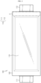
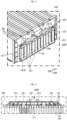
- FIG. 1 is a perspective view schematically showing a battery module according to an embodiment of the present disclosure.
- FIG. 2 is a side view schematically showing a secondary battery employed at the battery module according to an embodiment of the present disclosure.
- a battery module 200 includes a cell assembly 210 and a bus bar assembly 220.
- the cell assembly 210 may include a plurality of secondary batteries 100 arranged in the right and left direction.
- the secondary battery 100 may be a pouch-type secondary battery 100.
- the pouch-type secondary battery 100 may include an electrode assembly, an electrolyte, and a pouch 120.
- the pouch 120 may have an accommodation portion 115 of a concave shape.
- the accommodation assembly 115 may accommodate the electrode assembly (not shown) and the electrolyte (not shown).
- the pouch includes an outer insulation layer, a metal layer and an inner adhesive layer, and the inner adhesive layers are adhered to each other at a rim portion of the pouch 120 to form a sealing portion.
- terrace portions S may be respectively formed at both ends of the pouch 120 where a positive electrode lead 111 and a negative electrode lead 112 are formed.
- the electrode assembly is an assembly of an electrode and a separator, and at least one positive electrode plate and at least one negative electrode plate may disposed with a separator interposed therebetween.
- the positive electrode plate of the electrode assembly includes a positive electrode tab, and at least one positive electrode tab may be connected to the positive electrode lead 111.
- one end of the positive electrode lead 111 is connected to the positive electrode tab and the other end thereof is exposed out of the pouch 120.
- the exposed portion may function as an electrode terminal of the secondary battery 100, for example a positive electrode terminal of the secondary battery 100.
- the negative electrode plate of the electrode assembly includes a negative electrode tab, and at least one negative electrode tab may be connected to the negative electrode lead 112. Also, one end of the negative electrode lead 112 is connected to the negative electrode tab and the other end thereof is exposed out of the pouch 120. The exposed portion may serve as an electrode terminal of the secondary battery 100, for example a negative electrode terminal of the secondary battery 100.
- the positive electrode lead 111 and the negative electrode lead 112 may be formed at both ends opposite to each other based on the center of the secondary battery 100. That is, the positive electrode lead 111 may be provided at one end portion with respect to the center of the secondary battery 100. In addition, the negative electrode lead 112 may be provided at the other end portion with respect to the center of the secondary battery 100.
- each secondary battery 100 may be respectively configured so that the positive electrode lead 111 and the negative electrode lead 112 protrude forward and backward, respectively.
- the positive electrode lead 111 and the negative electrode lead 112 may be configured to have a plate form.
- the positive electrode lead 111 and the negative electrode lead 112 may protrude horizontally in a standing state so that their broad surfaces face left and right.
- the secondary battery 100 may be provided in plural in the battery module 200, and the plurality of secondary batteries 100 may be arranged to be stacked in at least one direction.
- a plurality of pouch-type secondary batteries 100 may be stacked one on another in parallel in the right and left direction.
- each pouch-type secondary battery 100 may be disposed to stand approximately perpendicular to the ground so that two broad surfaces positioned are respectively located at left and right and the sealing portions are located at upper, lower, front and rear portions, when viewed in the direction F (shown in FIG. 1 ).
- each secondary battery 100 may be configured in a vertically standing form.
- the upper, lower, front, rear, right and left directions are set based on the direction F, unless otherwise specified.
- the battery module 200 according to the present disclosure is not limited to the pouch-type secondary battery 100 described above, and various kinds of secondary batteries 100 known at the time of filing of this application may be employed.
- FIG. 3 is a partially enlarged perspective view showing a portion C' of the battery module of FIG. 1 .
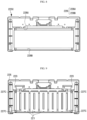
- FIG. 4 is a horizontally sectioned view schematically showing the battery module, taken along the line A-A' of FIG. 1 .
- the bus bar assembly 220 may be located at the front or rear of the cell assembly 210.
- the bus bar assembly 220 includes a plurality of bus bars 221 and a bus bar frame 225.
- the bus bar 221 may have a conductive material to electrically connect the plurality of secondary batteries 100. That is, the bus bar 221 may have a conductive material with relatively high electrical conductivity at a region that is in contact with the electrode lead 111 provided at each of the plurality of secondary batteries 100.
- the bus bar may have a copper alloy, or an aluminum alloy.
- the bus bar 221 may contact a plurality of electrode leads 111 of the same polarity or a plurality of electrode leads 112 of different polarities to electrically connect the plurality of secondary batteries 100.
- the bus bar 221 may have a metal plate shape.
- the metal plate shape may have a bar shape elongated in one direction.
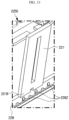
- bus bar frame 225 may have a bus bar fixing portion 226 configured to fix a top end 221U and a bottom end 221B of the bus bar 221.
- an insert groove 228U having an upward recess elongated in the right and left direction and into which the top end 221U of the bus bar 221 is inserted and an insert groove 228B having a downward recess elongated in the right and left direction into which the bottom end 221B of the bus bar 221 is inserted may be formed at the outer side surface of the bus bar frame 225C.
- the battery pack according to the present disclosure may be applied to a vehicle such as an electric vehicle.
- the vehicle according to the present disclosure may include the above battery pack.
- Reference Signs 200 battery module 210: cell assembly 100: secondary battery 220: bus bar assembly 221: bus bar 225: bus bar frame 223: module bus bar 240: module terminal 226: bus bar fixing portion 229: bus bar open portion H1: opening H2: perforation hole 227: hook structure 228: insert groove 228P: fixing protrusion 221G: fitting groove 224: distance adjusting rod 228Z: compressing protrusion
Landscapes
- Chemical & Material Sciences (AREA)
- Chemical Kinetics & Catalysis (AREA)
- Electrochemistry (AREA)
- General Chemical & Material Sciences (AREA)
- Engineering & Computer Science (AREA)
- Microelectronics & Electronic Packaging (AREA)
- Manufacturing & Machinery (AREA)
- Inorganic Chemistry (AREA)
- Connection Of Batteries Or Terminals (AREA)
- Battery Mounting, Suspending (AREA)
Claims (8)
- Batteriemodul (200), umfassend:eine Zellenanordnung (210), welche eine Mehrzahl von Sekundärbatterien (100) umfasst, welche jeweils eine Mehrzahl von Elektrodenleitungen (111) aufweisen und dazu angeordnet sind, in wenigstens einer Richtung gestapelt zu sein; undeine Sammelschienen-Anordnung (220), welche eine Mehrzahl von Sammelschienen (221), welche dazu eingerichtet sind, die Mehrzahl von Sekundärbatterien (100) elektrisch zu verbinden, und wenigstens ein Perforationsloch (H2) aufweisen, in welche die Elektrodenleitungen (111) eingesetzt sind, sowie einen Sammelschienen-Rahmen (225) umfasst, welcher derart eingerichtet ist, dass die Mehrzahl von Sammelschienen (221) an einer äußeren Seitenfläche davon montiert sind,wobei der Sammelschienen-Rahmen (225) umfasst:einen Sammelschienen-Befestigungsabschnitt (226), welcher einen Einsatzraum aufweist, welcher in der rechten und linken Richtung länglich ist, so dass eine Position der Sammelschiene (221) in der rechten und linken Richtung frei gesetzt wird, wobei der Sammelschienen-Befestigungsabschnitt dazu eingerichtet ist, ein oberes Ende (221U) und ein unteres Ende (221B) der Sammelschiene (221) zu befestigen; undeinen Sammelschienen-Öffnungsabschnitt (229), welcher derart geöffnet ist, dass das Perforationsloch (H2) der Sammelschiene nach innen freigelegt ist, wenn die Position der Sammelschiene (221) in der rechten und linken Richtung geändert wird, und wobei die Sammelschiene (221) eine Plattenform aufweist, undwobei ein Perforationsloch (H2), welches in der vorderen und hinteren Richtung perforiert ist, in der Plattenform der Sammelschiene (221) gebildet ist, undwobei der Sammelschienen-Befestigungsabschnitt (226) eine Einsetznut (228) aufweist, in welche wenigstens eines aus dem oberen Ende (221U) und dem unteren Ende (221B) der Sammelschiene (221) eingesetzt ist, wobei die Einsetznut (228) eine Ausnehmung nach oben oder unten aufweist, welche in der rechten und linken Richtung länglich ist, undwobei eine Mehrzahl von Befestigungsvorsprüngen (228P), welche in Richtung der Sammelschiene (221) vorstehen, bei vorbestimmten Intervallen an einer inneren Fläche der Einsetznut (228) gebildet sind, und eine Passnut (221G), welche eine Ausnehmung nach oben aufweist, an einem Ende der Sammelschiene (221) gebildet ist, so dass der Befestigungsvorsprung (228P) darin eingesetzt ist.
- Batteriemodul (200) nach Anspruch 1,
wobei der Sammelschienen-Befestigungsabschnitt (226) eine Hakenstruktur (227) aufweist, deren Hakenform in der rechten und linken Richtung länglich ist, um wenigstens eines aus dem oberen Ende (221U) und dem unteren Ende (221B) der Sammelschiene (221) in die Richtung nach innen zu pressen. - Batteriemodul (200) nach Anspruch 1,
wobei ein Distanz-Einstellstab (224), welcher zwischen der Mehrzahl von Sammelschienen (221) angeordnet und in der rechten und linken Richtung länglich ist, in die Einsetznut (228) eingesetzt ist. - Batteriemodul (200) nach Anspruch 1,
wobei ein Kompressionsvorsprung (228Z), welcher dazu eingerichtet ist, das untere Ende der Sammelschiene (221) in die Richtung nach außen zu pressen, an einer inneren Fläche der Einsetznut (228) gebildet ist. - Batteriemodul (200) nach Anspruch 1,
wobei der Sammelschienen-Öffnungsabschnitt (229) in einer Länge größer als die Länge der Sammelschiene (221) in der rechten und linken Richtung geöffnet ist. - Batteriemodul (200) nach Anspruch 5,
wobei der Sammelschienen-Öffnungsabschnitt (229) eine einzelne Öffnung aufweist, so dass eine hintere Fläche der Mehrzahl von Sammelschienen (221), welche an der äußeren Seitenfläche montiert sind, teilweise nach innen freigelegt ist. - Batteriepack, umfassend wenigstens ein Batteriemodul (200), welches in einem der Ansprüche 1 bis 6 definiert ist.
- Fahrzeug, umfassend den Batteriepack, welcher in Anspruch 7 definiert ist.
Applications Claiming Priority (2)
| Application Number | Priority Date | Filing Date | Title |
|---|---|---|---|
| KR1020170172515A KR102259416B1 (ko) | 2017-12-14 | 2017-12-14 | 버스바 어셈블리를 포함하는 배터리 모듈 |
| PCT/KR2018/015010 WO2019117514A1 (ko) | 2017-12-14 | 2018-11-29 | 버스바 어셈블리를 포함하는 배터리 모듈 |
Publications (3)
| Publication Number | Publication Date |
|---|---|
| EP3637503A1 EP3637503A1 (de) | 2020-04-15 |
| EP3637503A4 EP3637503A4 (de) | 2020-12-02 |
| EP3637503B1 true EP3637503B1 (de) | 2025-03-26 |
Family
ID=66820536
Family Applications (1)
| Application Number | Title | Priority Date | Filing Date |
|---|---|---|---|
| EP18889754.0A Active EP3637503B1 (de) | 2017-12-14 | 2018-11-29 | Batteriemodul mit busschienenanordnung |
Country Status (9)
| Country | Link |
|---|---|
| US (1) | US11223093B2 (de) |
| EP (1) | EP3637503B1 (de) |
| JP (1) | JP7045588B2 (de) |
| KR (1) | KR102259416B1 (de) |
| CN (1) | CN110915024B (de) |
| ES (1) | ES3021240T3 (de) |
| HU (1) | HUE071177T2 (de) |
| PL (1) | PL3637503T3 (de) |
| WO (1) | WO2019117514A1 (de) |
Families Citing this family (50)
| Publication number | Priority date | Publication date | Assignee | Title |
|---|---|---|---|---|
| KR102532699B1 (ko) * | 2019-06-25 | 2023-05-12 | 주식회사 엘지에너지솔루션 | 전지 모듈 및 이를 포함하는 전지팩 |
| KR102541537B1 (ko) * | 2019-06-25 | 2023-06-08 | 주식회사 엘지에너지솔루션 | 전지 모듈 및 이를 포함하는 전지팩 |
| KR102583650B1 (ko) * | 2019-07-01 | 2023-09-26 | 주식회사 엘지에너지솔루션 | 전지 모듈 및 이를 포함하는 전지팩 |
| KR102785549B1 (ko) * | 2019-08-02 | 2025-03-26 | 주식회사 엘지에너지솔루션 | 이동 가능한 버스바 조립체를 구비한 배터리 팩 및 이를 포함하는 이차전지 |
| KR102860575B1 (ko) * | 2019-08-23 | 2025-09-15 | 주식회사 엘지에너지솔루션 | 전지 모듈 및 이를 포함하는 전지 팩 |
| KR102792208B1 (ko) * | 2019-09-11 | 2025-04-04 | 주식회사 엘지에너지솔루션 | 전지 모듈 및 이를 포함하는 전지 팩 |
| CN112582719B (zh) * | 2019-09-29 | 2022-04-29 | 东莞新能源科技有限公司 | 电池模组单元、电池模组、储能系统及电动车辆 |
| KR102795269B1 (ko) * | 2019-10-07 | 2025-04-15 | 주식회사 엘지에너지솔루션 | 전지셀의 리드와 버스바의 기계적 연결구조를 갖는 전지모듈 |
| KR102473336B1 (ko) | 2019-10-07 | 2022-12-01 | 주식회사 엘지에너지솔루션 | 전지 모듈 및 이를 포함하는 전지팩 |
| KR102772767B1 (ko) | 2020-01-03 | 2025-02-24 | 주식회사 엘지에너지솔루션 | 전지 모듈 및 이를 포함하는 전지팩 |
| KR102862762B1 (ko) * | 2020-02-13 | 2025-09-19 | 주식회사 엘지에너지솔루션 | 배터리 모듈, 이러한 배터리 모듈을 포함하는 배터리 팩 및 자동차 |
| KR102862773B1 (ko) * | 2020-02-17 | 2025-09-19 | 주식회사 엘지에너지솔루션 | 배터리 모듈, 이러한 배터리 모듈을 포함하는 배터리 팩 및 자동차 |
| WO2021206350A1 (ko) * | 2020-04-09 | 2021-10-14 | 주식회사 엘지에너지솔루션 | 전지 모듈 및 이를 포함하는 전지팩 |
| KR20210132397A (ko) | 2020-04-27 | 2021-11-04 | 주식회사 엘지에너지솔루션 | 전지 모듈 및 이를 포함하는 전지팩 |
| CN111554848A (zh) * | 2020-05-18 | 2020-08-18 | 桑顿新能源科技(长沙)有限公司 | 模组箱体、软包锂电池模组 |
| KR102802982B1 (ko) * | 2020-07-06 | 2025-04-30 | 주식회사 엘지에너지솔루션 | 전지 모듈 및 이를 포함하는 전지팩 |
| KR102892920B1 (ko) | 2020-07-14 | 2025-11-28 | 주식회사 엘지에너지솔루션 | 전지 팩 및 이를 포함하는 디바이스 |
| JP7590130B2 (ja) | 2020-07-17 | 2024-11-26 | 株式会社オートネットワーク技術研究所 | 配線モジュール |
| KR102861724B1 (ko) * | 2020-07-21 | 2025-09-17 | 주식회사 엘지에너지솔루션 | 개선된 전극 리드 연결 구조를 갖는 배터리 모듈, 그리고 이를 포함하는 배터리 팩 및 자동차 |
| KR102842539B1 (ko) * | 2020-07-21 | 2025-08-04 | 주식회사 엘지에너지솔루션 | 전지 모듈 및 이를 포함하는 전지팩 |
| KR102951291B1 (ko) | 2020-07-22 | 2026-04-09 | 주식회사 엘지에너지솔루션 | 전극 리드와 전압 센싱부재 간의 연결을 단순화한 배터리 모듈 및 이를 포함하는 배터리 팩 |
| KR102821825B1 (ko) | 2020-07-22 | 2025-06-16 | 주식회사 엘지에너지솔루션 | 전극 리드와 전압 센싱부재 간의 연결을 단순화한 배터리 모듈 및 이를 포함하는 배터리 팩 |
| KR20220040869A (ko) * | 2020-09-24 | 2022-03-31 | 현대자동차주식회사 | 배터리 모듈 및 이를 포함하는 배터리 팩 |
| KR102848526B1 (ko) * | 2020-10-26 | 2025-08-21 | 주식회사 엘지에너지솔루션 | 배터리 모듈 센싱 유닛, 배터리 모듈, 배터리 팩 및 배터리 모듈 센싱 유닛의 제조방법 |
| KR102567485B1 (ko) * | 2020-11-03 | 2023-08-17 | 한국단자공업 주식회사 | 배터리용 전기적 연결장치 및 그 제조방법 |
| KR102917117B1 (ko) * | 2020-11-05 | 2026-01-22 | 주식회사 엘지에너지솔루션 | 전지 모듈 및 이를 포함하는 전지팩 |
| KR102866659B1 (ko) * | 2020-11-10 | 2025-09-29 | 주식회사 엘지에너지솔루션 | 전압 센싱 부품들의 조립 구조를 개선한 배터리 모듈 및 이를 포함하는 배터리 팩 |
| KR102875637B1 (ko) * | 2020-11-27 | 2025-10-22 | 주식회사 엘지에너지솔루션 | 배터리 모듈, 배터리 팩, 및 전력 저장 장치 |
| KR102929086B1 (ko) * | 2020-12-29 | 2026-02-23 | 에스케이온 주식회사 | 배터리모듈 |
| CN116075974B (zh) * | 2021-01-19 | 2026-03-06 | 株式会社Lg新能源 | 电池模块和包括该电池模块的电池组 |
| JP7459012B2 (ja) * | 2021-04-23 | 2024-04-01 | プライムプラネットエナジー&ソリューションズ株式会社 | ラミネートセルの接続構造、組電池およびラミネートセルの接続方法 |
| EP4203171B1 (de) * | 2021-05-03 | 2025-10-15 | LG Energy Solution, Ltd. | Batteriemodul und batteriepack damit |
| US11973205B2 (en) | 2021-09-16 | 2024-04-30 | Lunar Energy, Inc. | Cell temperature regulation |
| KR102637525B1 (ko) | 2021-10-26 | 2024-02-19 | 주식회사 엘지에너지솔루션 | 배터리 모듈 및 이를 포함한 배터리 팩 |
| KR102872638B1 (ko) | 2021-11-08 | 2025-10-16 | 주식회사 엘지에너지솔루션 | 배터리 모듈 및 이를 포함한 배터리 팩 |
| KR102734328B1 (ko) | 2021-11-12 | 2024-11-27 | 주식회사 엘지에너지솔루션 | 배터리 모듈 및 이를 포함한 배터리 팩 |
| KR102886196B1 (ko) | 2021-11-12 | 2025-11-13 | 주식회사 엘지에너지솔루션 | 배터리 모듈 및 이를 포함한 배터리 팩 |
| KR102656950B1 (ko) | 2021-11-12 | 2024-04-16 | 주식회사 엘지에너지솔루션 | 배터리 모듈 및 이를 포함한 배터리 팩 |
| CN216413212U (zh) * | 2021-12-01 | 2022-04-29 | 宁德时代新能源科技股份有限公司 | 汇流排组件、电池及用电装置 |
| KR102927974B1 (ko) * | 2021-12-17 | 2026-02-20 | 주식회사 엘지에너지솔루션 | 전해액 누액 검출기능이 구비된 전지 모듈 및 이를 포함하는 전지 팩 |
| CN116565430A (zh) * | 2022-01-27 | 2023-08-08 | 本田技研工业株式会社 | 电池组及单体集合体 |
| CN116742290A (zh) * | 2022-03-04 | 2023-09-12 | 比亚迪股份有限公司 | 一种电芯组件、电池包及车辆 |
| KR102952040B1 (ko) * | 2022-04-22 | 2026-04-14 | 현대모비스 주식회사 | 배터리 모듈 어셈블리 및 그 배터리 모듈 어셈블리의 제조 방법 |
| KR102832837B1 (ko) * | 2022-05-16 | 2025-07-09 | 주식회사 엘지에너지솔루션 | 배터리 팩 및 이를 포함하는 자동차 |
| KR102452156B1 (ko) * | 2022-06-16 | 2022-10-12 | 덕양산업 주식회사 | 배터리팩용 버스바 고정브라켓 |
| KR102915631B1 (ko) * | 2022-11-17 | 2026-01-21 | 주식회사 엘지에너지솔루션 | 상하단 분리형 버스바프레임을 포함하는 배터리 모듈 및 이를 조립하는 방법 |
| KR102817210B1 (ko) * | 2023-07-27 | 2025-06-09 | 주식회사 카펙발레오 | 버스바 지지 브라켓과 이를 적용한 배터리 팩, 및 이를 탑재한 차량 |
| EP4601089A1 (de) * | 2024-02-06 | 2025-08-13 | LG Energy Solution, Ltd. | Batteriezellenanordnung, batteriepack und transportvorrichtung damit |
| KR20260004016A (ko) * | 2024-07-01 | 2026-01-08 | 주식회사 엘지에너지솔루션 | 버스바 프레임 어셈블리 및 이를 포함하는 전지 모듈 |
| KR20260046649A (ko) * | 2024-09-30 | 2026-04-07 | 주식회사 엘지에너지솔루션 | 배터리 모듈, 이를 포함하는 배터리 팩 및 자동차 |
Family Cites Families (35)
| Publication number | Priority date | Publication date | Assignee | Title |
|---|---|---|---|---|
| JP5449814B2 (ja) | 2009-03-25 | 2014-03-19 | 三洋電機株式会社 | 組電池 |
| US8580423B2 (en) | 2009-10-22 | 2013-11-12 | Samsung Sdi Co., Ltd. | Bus bar holder and battery pack including the same |
| KR101201747B1 (ko) | 2010-05-24 | 2012-11-15 | 에스비리모티브 주식회사 | 전지 모듈 |
| KR101217564B1 (ko) | 2010-08-16 | 2013-01-02 | 주식회사 엘지화학 | 전압 검출 어셈블리 및 이를 포함하는 전지모듈 |
| KR102024002B1 (ko) * | 2012-07-05 | 2019-09-23 | 에스케이이노베이션 주식회사 | 전지팩 |
| JP2014032949A (ja) * | 2012-07-13 | 2014-02-20 | Toyota Motor Corp | 蓄電装置の収容庫及びバスバーユニット |
| JP6234929B2 (ja) | 2012-08-30 | 2017-11-22 | 三洋電機株式会社 | 電源装置及び電源装置を備える車両並びに蓄電装置、電源装置の製造方 |
| KR101732285B1 (ko) | 2012-11-09 | 2017-05-02 | 닛산 지도우샤 가부시키가이샤 | 조전지 및 조전지의 제조 방법 |
| KR20140060633A (ko) * | 2012-11-12 | 2014-05-21 | 주식회사 엘지화학 | 버스 바 어셈블리를 포함하는 전지모듈 및 이를 포함하는 전지팩 |
| JP6107091B2 (ja) | 2012-12-04 | 2017-04-05 | 日産自動車株式会社 | 組電池および組電池の製造方法 |
| JP2014116160A (ja) | 2012-12-07 | 2014-06-26 | Yazaki Corp | 電源装置 |
| KR102046122B1 (ko) * | 2013-05-21 | 2019-11-19 | 에스케이이노베이션 주식회사 | Pcb접속유닛 및 이를 이용한 전지모듈제작방법과 상기 방법에 의해 제작된 전지모듈 |
| JP6145314B2 (ja) * | 2013-05-29 | 2017-06-07 | 矢崎総業株式会社 | バスバモジュール及び電源装置 |
| JP6016737B2 (ja) | 2013-08-29 | 2016-10-26 | 古河電気工業株式会社 | 電池パックの電池内配線モジュール |
| JP6011876B2 (ja) | 2013-09-13 | 2016-10-19 | 株式会社オートネットワーク技術研究所 | 蓄電モジュール |
| KR101632339B1 (ko) | 2013-10-31 | 2016-06-21 | 주식회사 엘지화학 | 외부 충격을 흡수할 수 있는 배터리 팩 조립체 |
| KR102263304B1 (ko) | 2013-11-05 | 2021-06-15 | 타이코에이엠피 주식회사 | 배터리 셀 연결보드 |
| KR101667519B1 (ko) * | 2013-12-17 | 2016-10-28 | 주식회사 엘지화학 | 외부 입출력 단자를 형성하는 버스 바를 포함하는 전지모듈 |
| WO2015152527A1 (ko) * | 2014-03-31 | 2015-10-08 | 주식회사 엘지화학 | 배터리 모듈 및 이를 포함하는 배터리 팩 |
| JP2015230892A (ja) * | 2014-06-09 | 2015-12-21 | ソニー株式会社 | 電池モジュール、蓄電装置、蓄電システム、電子機器、電動車両および電力システム |
| KR101640100B1 (ko) | 2014-11-10 | 2016-07-18 | 한국단자공업 주식회사 | 배터리모듈용 직렬연결장치 |
| US9755212B2 (en) | 2014-11-11 | 2017-09-05 | Ford Global Technologies, Llc | Traction battery busbar carriers for pouch battery cells |
| KR101797687B1 (ko) | 2014-12-22 | 2017-11-15 | 주식회사 엘지화학 | 외부 이물질의 유입을 방지하는 유입방지 부재를 포함하는 전지셀 상호 연결 보드 |
| KR102381777B1 (ko) * | 2015-02-25 | 2022-04-01 | 삼성에스디아이 주식회사 | 배터리 팩 |
| DE102015217644A1 (de) * | 2015-09-15 | 2017-03-16 | Robert Bosch Gmbh | Deckelelement eines Batteriemodulgehäuses, Batteriemodul mit einem solchen Deckelelement und Verfahren zu dessen Herstellung sowie Batterie |
| JP6309499B2 (ja) | 2015-09-18 | 2018-04-11 | 矢崎総業株式会社 | バスバモジュール及び電池パック |
| JP6717581B2 (ja) | 2015-10-22 | 2020-07-01 | 株式会社エンビジョンAescジャパン | 組電池および組電池用のスペーサ |
| KR102047482B1 (ko) * | 2015-10-30 | 2019-12-02 | 주식회사 엘지화학 | 배터리 모듈 및 이를 포함하는 배터리 팩 |
| KR200491844Y1 (ko) | 2015-11-12 | 2020-06-16 | 한국단자공업 주식회사 | 배터리모듈용 직렬연결장치 |
| KR102032356B1 (ko) | 2015-12-07 | 2019-11-08 | 주식회사 엘지화학 | 전지모듈용 전압 센싱 블록 |
| KR200485016Y1 (ko) | 2015-12-11 | 2017-12-12 | 한국단자공업 주식회사 | 배터리모듈용 직렬연결장치 |
| KR102093943B1 (ko) | 2016-02-12 | 2020-03-26 | 주식회사 엘지화학 | 배터리 모듈, 이러한 배터리 모듈을 포함하는 배터리 팩 및 이러한 배터리 팩을 포함하는 자동차 |
| KR102093944B1 (ko) | 2016-02-12 | 2020-03-26 | 주식회사 엘지화학 | 배터리 모듈, 이러한 배터리 모듈을 포함하는 배터리 팩 및 이러한 배터리 팩을 포함하는 자동차 |
| KR102034208B1 (ko) * | 2016-03-03 | 2019-10-18 | 주식회사 엘지화학 | 배터리 모듈, 이러한 배터리 모듈을 포함하는 배터리 팩 및 이러한 배터리 팩을 포함하는 자동차 |
| JP6650326B2 (ja) | 2016-04-01 | 2020-02-19 | 株式会社エンビジョンAescジャパン | 組電池および組電池の製造方法 |
-
2017
- 2017-12-14 KR KR1020170172515A patent/KR102259416B1/ko active Active
-
2018
- 2018-11-29 CN CN201880036425.4A patent/CN110915024B/zh active Active
- 2018-11-29 PL PL18889754.0T patent/PL3637503T3/pl unknown
- 2018-11-29 HU HUE18889754A patent/HUE071177T2/hu unknown
- 2018-11-29 ES ES18889754T patent/ES3021240T3/es active Active
- 2018-11-29 JP JP2019560340A patent/JP7045588B2/ja active Active
- 2018-11-29 US US16/611,353 patent/US11223093B2/en active Active
- 2018-11-29 EP EP18889754.0A patent/EP3637503B1/de active Active
- 2018-11-29 WO PCT/KR2018/015010 patent/WO2019117514A1/ko not_active Ceased
Also Published As
| Publication number | Publication date |
|---|---|
| ES3021240T3 (en) | 2025-05-26 |
| EP3637503A4 (de) | 2020-12-02 |
| US11223093B2 (en) | 2022-01-11 |
| JP7045588B2 (ja) | 2022-04-01 |
| US20200144580A1 (en) | 2020-05-07 |
| KR102259416B1 (ko) | 2021-06-01 |
| PL3637503T3 (pl) | 2025-06-09 |
| EP3637503A1 (de) | 2020-04-15 |
| KR20190071454A (ko) | 2019-06-24 |
| CN110915024A (zh) | 2020-03-24 |
| WO2019117514A1 (ko) | 2019-06-20 |
| HUE071177T2 (hu) | 2025-08-28 |
| CN110915024B (zh) | 2022-06-10 |
| JP2020518988A (ja) | 2020-06-25 |
Similar Documents
| Publication | Publication Date | Title |
|---|---|---|
| EP3637503B1 (de) | Batteriemodul mit busschienenanordnung | |
| KR102392767B1 (ko) | 내측 커버를 포함하는 배터리 모듈 | |
| CN110710051B (zh) | 电池组 | |
| US10096867B2 (en) | Compact secondary battery module integrated with BMS | |
| EP2282363B1 (de) | Batteriepack mit Einzelzellen in einem Abstandshalter | |
| EP3937299A1 (de) | Batteriemodul und batteriesatz | |
| KR102792413B1 (ko) | 버스바를 구비한 배터리 모듈, 및 배터리 팩, 및 자동차 | |
| CN110770946A (zh) | 易于组装的包括汇流条框架的电池模块 | |
| EP3035434A1 (de) | Batteriemodul | |
| US11205817B2 (en) | Battery pack | |
| EP2849262A1 (de) | Batteriezelle mit amorpher struktur und batteriemodul damit | |
| US20130045401A1 (en) | Battery pack and battery module comprising the same | |
| CN109891626A (zh) | 电池组 | |
| US11984612B2 (en) | Battery module comprising module housing | |
| JP6594455B2 (ja) | ワイヤー固定リブを備えている電池モジュール | |
| KR102937187B1 (ko) | 배터리 모듈, 이를 포함하는 배터리 팩, 및 자동차 | |
| KR102809421B1 (ko) | 배터리 모듈, 그것을 포함하는 배터리 팩, 및 자동차 | |
| JP4744096B2 (ja) | パック電池 | |
| CN108023042A (zh) | 用于接收袋装电池的电池框架 | |
| JP6338905B2 (ja) | バッテリシステム | |
| KR101839653B1 (ko) | 컴팩트 이차전지 모듈 | |
| KR101658587B1 (ko) | 리튬 이차전지 및 이를 포함하는 전지팩 | |
| JP7566029B2 (ja) | バッテリーモジュール、それを含むバッテリーパック及び自動車 | |
| EP4175036A1 (de) | Batteriemodul, batteriepack und energiespeichervorrichtung | |
| KR20260056765A (ko) | 터미널 버스바 및 배터리 팩 |
Legal Events
| Date | Code | Title | Description |
|---|---|---|---|
| STAA | Information on the status of an ep patent application or granted ep patent |
Free format text: STATUS: THE INTERNATIONAL PUBLICATION HAS BEEN MADE |
|
| PUAI | Public reference made under article 153(3) epc to a published international application that has entered the european phase |
Free format text: ORIGINAL CODE: 0009012 |
|
| STAA | Information on the status of an ep patent application or granted ep patent |
Free format text: STATUS: REQUEST FOR EXAMINATION WAS MADE |
|
| 17P | Request for examination filed |
Effective date: 20200108 |
|
| AK | Designated contracting states |
Kind code of ref document: A1 Designated state(s): AL AT BE BG CH CY CZ DE DK EE ES FI FR GB GR HR HU IE IS IT LI LT LU LV MC MK MT NL NO PL PT RO RS SE SI SK SM TR |
|
| AX | Request for extension of the european patent |
Extension state: BA ME |
|
| A4 | Supplementary search report drawn up and despatched |
Effective date: 20201029 |
|
| RIC1 | Information provided on ipc code assigned before grant |
Ipc: H01M 2/10 20060101ALI20201023BHEP Ipc: H01M 2/20 20060101AFI20201023BHEP |
|
| DAV | Request for validation of the european patent (deleted) | ||
| DAX | Request for extension of the european patent (deleted) | ||
| RAP1 | Party data changed (applicant data changed or rights of an application transferred) |
Owner name: LG ENERGY SOLUTION LTD. |
|
| RAP3 | Party data changed (applicant data changed or rights of an application transferred) |
Owner name: LG ENERGY SOLUTION, LTD. |
|
| STAA | Information on the status of an ep patent application or granted ep patent |
Free format text: STATUS: EXAMINATION IS IN PROGRESS |
|
| 17Q | First examination report despatched |
Effective date: 20230621 |
|
| REG | Reference to a national code |
Ref country code: DE Ref legal event code: R079 Free format text: PREVIOUS MAIN CLASS: H01M0002200000 Ipc: H01M0050211000 Ref document number: 602018080583 Country of ref document: DE |
|
| GRAP | Despatch of communication of intention to grant a patent |
Free format text: ORIGINAL CODE: EPIDOSNIGR1 |
|
| STAA | Information on the status of an ep patent application or granted ep patent |
Free format text: STATUS: GRANT OF PATENT IS INTENDED |
|
| RIC1 | Information provided on ipc code assigned before grant |
Ipc: H01M 50/507 20210101ALI20241108BHEP Ipc: H01M 50/211 20210101AFI20241108BHEP |
|
| INTG | Intention to grant announced |
Effective date: 20241120 |
|
| P01 | Opt-out of the competence of the unified patent court (upc) registered |
Free format text: CASE NUMBER: APP_65640/2024 Effective date: 20241212 |
|
| GRAS | Grant fee paid |
Free format text: ORIGINAL CODE: EPIDOSNIGR3 |
|
| GRAA | (expected) grant |
Free format text: ORIGINAL CODE: 0009210 |
|
| STAA | Information on the status of an ep patent application or granted ep patent |
Free format text: STATUS: THE PATENT HAS BEEN GRANTED |
|
| AK | Designated contracting states |
Kind code of ref document: B1 Designated state(s): AL AT BE BG CH CY CZ DE DK EE ES FI FR GB GR HR HU IE IS IT LI LT LU LV MC MK MT NL NO PL PT RO RS SE SI SK SM TR |
|
| REG | Reference to a national code |
Ref country code: GB Ref legal event code: FG4D |
|
| REG | Reference to a national code |
Ref country code: CH Ref legal event code: EP |
|
| REG | Reference to a national code |
Ref country code: DE Ref legal event code: R096 Ref document number: 602018080583 Country of ref document: DE |
|
| REG | Reference to a national code |
Ref country code: IE Ref legal event code: FG4D |
|
| REG | Reference to a national code |
Ref country code: SE Ref legal event code: TRGR |
|
| REG | Reference to a national code |
Ref country code: ES Ref legal event code: FG2A Ref document number: 3021240 Country of ref document: ES Kind code of ref document: T3 Effective date: 20250526 |
|
| PG25 | Lapsed in a contracting state [announced via postgrant information from national office to epo] |
Ref country code: RS Free format text: LAPSE BECAUSE OF FAILURE TO SUBMIT A TRANSLATION OF THE DESCRIPTION OR TO PAY THE FEE WITHIN THE PRESCRIBED TIME-LIMIT Effective date: 20250626 |
|
| PG25 | Lapsed in a contracting state [announced via postgrant information from national office to epo] |
Ref country code: FI Free format text: LAPSE BECAUSE OF FAILURE TO SUBMIT A TRANSLATION OF THE DESCRIPTION OR TO PAY THE FEE WITHIN THE PRESCRIBED TIME-LIMIT Effective date: 20250326 |
|
| REG | Reference to a national code |
Ref country code: LT Ref legal event code: MG9D |
|
| PG25 | Lapsed in a contracting state [announced via postgrant information from national office to epo] |
Ref country code: NO Free format text: LAPSE BECAUSE OF FAILURE TO SUBMIT A TRANSLATION OF THE DESCRIPTION OR TO PAY THE FEE WITHIN THE PRESCRIBED TIME-LIMIT Effective date: 20250626 |
|
| PG25 | Lapsed in a contracting state [announced via postgrant information from national office to epo] |
Ref country code: HR Free format text: LAPSE BECAUSE OF FAILURE TO SUBMIT A TRANSLATION OF THE DESCRIPTION OR TO PAY THE FEE WITHIN THE PRESCRIBED TIME-LIMIT Effective date: 20250326 |
|
| PG25 | Lapsed in a contracting state [announced via postgrant information from national office to epo] |
Ref country code: LV Free format text: LAPSE BECAUSE OF FAILURE TO SUBMIT A TRANSLATION OF THE DESCRIPTION OR TO PAY THE FEE WITHIN THE PRESCRIBED TIME-LIMIT Effective date: 20250326 |
|
| PG25 | Lapsed in a contracting state [announced via postgrant information from national office to epo] |
Ref country code: GR Free format text: LAPSE BECAUSE OF FAILURE TO SUBMIT A TRANSLATION OF THE DESCRIPTION OR TO PAY THE FEE WITHIN THE PRESCRIBED TIME-LIMIT Effective date: 20250627 Ref country code: BG Free format text: LAPSE BECAUSE OF FAILURE TO SUBMIT A TRANSLATION OF THE DESCRIPTION OR TO PAY THE FEE WITHIN THE PRESCRIBED TIME-LIMIT Effective date: 20250326 |
|
| REG | Reference to a national code |
Ref country code: NL Ref legal event code: MP Effective date: 20250326 |
|
| PG25 | Lapsed in a contracting state [announced via postgrant information from national office to epo] |
Ref country code: NL Free format text: LAPSE BECAUSE OF FAILURE TO SUBMIT A TRANSLATION OF THE DESCRIPTION OR TO PAY THE FEE WITHIN THE PRESCRIBED TIME-LIMIT Effective date: 20250326 |
|
| REG | Reference to a national code |
Ref country code: HU Ref legal event code: AG4A Ref document number: E071177 Country of ref document: HU |
|
| REG | Reference to a national code |
Ref country code: AT Ref legal event code: MK05 Ref document number: 1779883 Country of ref document: AT Kind code of ref document: T Effective date: 20250326 |
|
| PG25 | Lapsed in a contracting state [announced via postgrant information from national office to epo] |
Ref country code: SM Free format text: LAPSE BECAUSE OF FAILURE TO SUBMIT A TRANSLATION OF THE DESCRIPTION OR TO PAY THE FEE WITHIN THE PRESCRIBED TIME-LIMIT Effective date: 20250326 |
|
| PG25 | Lapsed in a contracting state [announced via postgrant information from national office to epo] |
Ref country code: PT Free format text: LAPSE BECAUSE OF FAILURE TO SUBMIT A TRANSLATION OF THE DESCRIPTION OR TO PAY THE FEE WITHIN THE PRESCRIBED TIME-LIMIT Effective date: 20250728 |
|
| PG25 | Lapsed in a contracting state [announced via postgrant information from national office to epo] |
Ref country code: IT Free format text: LAPSE BECAUSE OF FAILURE TO SUBMIT A TRANSLATION OF THE DESCRIPTION OR TO PAY THE FEE WITHIN THE PRESCRIBED TIME-LIMIT Effective date: 20250326 |
|
| PG25 | Lapsed in a contracting state [announced via postgrant information from national office to epo] |
Ref country code: AT Free format text: LAPSE BECAUSE OF FAILURE TO SUBMIT A TRANSLATION OF THE DESCRIPTION OR TO PAY THE FEE WITHIN THE PRESCRIBED TIME-LIMIT Effective date: 20250326 |
|
| PG25 | Lapsed in a contracting state [announced via postgrant information from national office to epo] |
Ref country code: EE Free format text: LAPSE BECAUSE OF FAILURE TO SUBMIT A TRANSLATION OF THE DESCRIPTION OR TO PAY THE FEE WITHIN THE PRESCRIBED TIME-LIMIT Effective date: 20250326 |
|
| PG25 | Lapsed in a contracting state [announced via postgrant information from national office to epo] |
Ref country code: RO Free format text: LAPSE BECAUSE OF FAILURE TO SUBMIT A TRANSLATION OF THE DESCRIPTION OR TO PAY THE FEE WITHIN THE PRESCRIBED TIME-LIMIT Effective date: 20250326 |
|
| PG25 | Lapsed in a contracting state [announced via postgrant information from national office to epo] |
Ref country code: SK Free format text: LAPSE BECAUSE OF FAILURE TO SUBMIT A TRANSLATION OF THE DESCRIPTION OR TO PAY THE FEE WITHIN THE PRESCRIBED TIME-LIMIT Effective date: 20250326 |
|
| PG25 | Lapsed in a contracting state [announced via postgrant information from national office to epo] |
Ref country code: IS Free format text: LAPSE BECAUSE OF FAILURE TO SUBMIT A TRANSLATION OF THE DESCRIPTION OR TO PAY THE FEE WITHIN THE PRESCRIBED TIME-LIMIT Effective date: 20250726 |
|
| PGFP | Annual fee paid to national office [announced via postgrant information from national office to epo] |
Ref country code: HU Payment date: 20251127 Year of fee payment: 8 |
|
| REG | Reference to a national code |
Ref country code: DE Ref legal event code: R097 Ref document number: 602018080583 Country of ref document: DE |
|
| PGFP | Annual fee paid to national office [announced via postgrant information from national office to epo] |
Ref country code: DE Payment date: 20251020 Year of fee payment: 8 |
|
| PGFP | Annual fee paid to national office [announced via postgrant information from national office to epo] |
Ref country code: GB Payment date: 20251023 Year of fee payment: 8 |
|
| PG25 | Lapsed in a contracting state [announced via postgrant information from national office to epo] |
Ref country code: DK Free format text: LAPSE BECAUSE OF FAILURE TO SUBMIT A TRANSLATION OF THE DESCRIPTION OR TO PAY THE FEE WITHIN THE PRESCRIBED TIME-LIMIT Effective date: 20250326 |
|
| PGFP | Annual fee paid to national office [announced via postgrant information from national office to epo] |
Ref country code: FR Payment date: 20251021 Year of fee payment: 8 |
|
| PGFP | Annual fee paid to national office [announced via postgrant information from national office to epo] |
Ref country code: BE Payment date: 20251020 Year of fee payment: 8 |
|
| PGFP | Annual fee paid to national office [announced via postgrant information from national office to epo] |
Ref country code: SE Payment date: 20251021 Year of fee payment: 8 |
|
| PG25 | Lapsed in a contracting state [announced via postgrant information from national office to epo] |
Ref country code: CZ Free format text: LAPSE BECAUSE OF FAILURE TO SUBMIT A TRANSLATION OF THE DESCRIPTION OR TO PAY THE FEE WITHIN THE PRESCRIBED TIME-LIMIT Effective date: 20250326 |
|
| PGFP | Annual fee paid to national office [announced via postgrant information from national office to epo] |
Ref country code: PL Payment date: 20251020 Year of fee payment: 8 |
|
| PGFP | Annual fee paid to national office [announced via postgrant information from national office to epo] |
Ref country code: ES Payment date: 20251215 Year of fee payment: 8 |
|
| PLBE | No opposition filed within time limit |
Free format text: ORIGINAL CODE: 0009261 |
|
| STAA | Information on the status of an ep patent application or granted ep patent |
Free format text: STATUS: NO OPPOSITION FILED WITHIN TIME LIMIT |
|
| REG | Reference to a national code |
Ref country code: CH Ref legal event code: L10 Free format text: ST27 STATUS EVENT CODE: U-0-0-L10-L00 (AS PROVIDED BY THE NATIONAL OFFICE) Effective date: 20260211 |
|
| 26N | No opposition filed |
Effective date: 20260105 |