EP3637794B1 - Équipement portable sur la tête comportant un dispositif acoustique à conduction osseuse réglable - Google Patents
Équipement portable sur la tête comportant un dispositif acoustique à conduction osseuse réglable Download PDFInfo
- Publication number
- EP3637794B1 EP3637794B1 EP19172012.7A EP19172012A EP3637794B1 EP 3637794 B1 EP3637794 B1 EP 3637794B1 EP 19172012 A EP19172012 A EP 19172012A EP 3637794 B1 EP3637794 B1 EP 3637794B1
- Authority
- EP
- European Patent Office
- Prior art keywords
- rotating shaft
- housing
- bone
- conductive
- connection
- Prior art date
- Legal status (The legal status is an assumption and is not a legal conclusion. Google has not performed a legal analysis and makes no representation as to the accuracy of the status listed.)
- Active
Links
Images



Classifications
-
- H—ELECTRICITY
- H04—ELECTRIC COMMUNICATION TECHNIQUE
- H04R—LOUDSPEAKERS, MICROPHONES, GRAMOPHONE PICK-UPS OR LIKE ACOUSTIC ELECTROMECHANICAL TRANSDUCERS; ELECTRIC HEARING AIDS; PUBLIC ADDRESS SYSTEMS
- H04R5/00—Stereophonic arrangements
- H04R5/033—Headphones for stereophonic communication
- H04R5/0335—Earpiece support, e.g. headbands or neckrests
-
- H—ELECTRICITY
- H04—ELECTRIC COMMUNICATION TECHNIQUE
- H04R—LOUDSPEAKERS, MICROPHONES, GRAMOPHONE PICK-UPS OR LIKE ACOUSTIC ELECTROMECHANICAL TRANSDUCERS; ELECTRIC HEARING AIDS; PUBLIC ADDRESS SYSTEMS
- H04R9/00—Transducers of moving-coil, moving-strip, or moving-wire type
- H04R9/02—Details
- H04R9/04—Construction, mounting, or centering of coil
- H04R9/045—Mounting
-
- G—PHYSICS
- G06—COMPUTING OR CALCULATING; COUNTING
- G06F—ELECTRIC DIGITAL DATA PROCESSING
- G06F3/00—Input arrangements for transferring data to be processed into a form capable of being handled by the computer; Output arrangements for transferring data from processing unit to output unit, e.g. interface arrangements
- G06F3/01—Input arrangements or combined input and output arrangements for interaction between user and computer
- G06F3/011—Arrangements for interaction with the human body, e.g. for user immersion in virtual reality
- G06F3/012—Head tracking input arrangements
-
- G—PHYSICS
- G06—COMPUTING OR CALCULATING; COUNTING
- G06F—ELECTRIC DIGITAL DATA PROCESSING
- G06F3/00—Input arrangements for transferring data to be processed into a form capable of being handled by the computer; Output arrangements for transferring data from processing unit to output unit, e.g. interface arrangements
- G06F3/01—Input arrangements or combined input and output arrangements for interaction between user and computer
- G06F3/011—Arrangements for interaction with the human body, e.g. for user immersion in virtual reality
- G06F3/013—Eye tracking input arrangements
-
- H—ELECTRICITY
- H04—ELECTRIC COMMUNICATION TECHNIQUE
- H04R—LOUDSPEAKERS, MICROPHONES, GRAMOPHONE PICK-UPS OR LIKE ACOUSTIC ELECTROMECHANICAL TRANSDUCERS; ELECTRIC HEARING AIDS; PUBLIC ADDRESS SYSTEMS
- H04R31/00—Apparatus or processes specially adapted for the manufacture of transducers or diaphragms therefor
-
- G—PHYSICS
- G02—OPTICS
- G02B—OPTICAL ELEMENTS, SYSTEMS OR APPARATUS
- G02B27/00—Optical systems or apparatus not provided for by any of the groups G02B1/00 - G02B26/00, G02B30/00
- G02B27/01—Head-up displays
- G02B27/017—Head mounted
- G02B2027/0178—Eyeglass type
-
- G—PHYSICS
- G02—OPTICS
- G02B—OPTICAL ELEMENTS, SYSTEMS OR APPARATUS
- G02B27/00—Optical systems or apparatus not provided for by any of the groups G02B1/00 - G02B26/00, G02B30/00
- G02B27/01—Head-up displays
- G02B27/017—Head mounted
- G02B27/0176—Head mounted characterised by mechanical features
-
- H—ELECTRICITY
- H04—ELECTRIC COMMUNICATION TECHNIQUE
- H04R—LOUDSPEAKERS, MICROPHONES, GRAMOPHONE PICK-UPS OR LIKE ACOUSTIC ELECTROMECHANICAL TRANSDUCERS; ELECTRIC HEARING AIDS; PUBLIC ADDRESS SYSTEMS
- H04R2460/00—Details of hearing devices, i.e. of ear- or headphones covered by H04R1/10 or H04R5/033 but not provided for in any of their subgroups, or of hearing aids covered by H04R25/00 but not provided for in any of its subgroups
- H04R2460/13—Hearing devices using bone conduction transducers
Definitions
- the present disclosure relates to the field of wearable equipment, and more particularly to a head wearable equipment with an adjustable bone-conductive acoustic device.
- Bone-conduction is one kind of sound conduction, which converts the sound into mechanical vibration of different frequencies, and transmits sound waves through human skull, bone labyrinth, inner ear lymphatic transmission, auger, auditory nerve, and auditory center. Compared to the classical sound transmission method that produces sound waves through the diaphragm, bone-conduction cancels many steps of sound wave transmission, enabling clear sound reproduction in noisy environments, and sound waves will not influence other people on account of spreading in the air.
- the original acoustic device utilizing bone-conduction mainly includes a bone-conductive earphone and a bone-conductive microphone.
- the main structure of most of the current bone-conductive earphones includes two earphone portions and a rear connection rod connecting the earphone portions (as disclosed in US2014/0185837A1 or CN205179304U ), and usually the earphone portions are fixed.
- the adaption of the bone-conductive earphone to the wearer's head form or facial form is adjusted mainly by adjusting the rear connection rod.
- the bone-conductive earphone is integrated into other types of head wearable equipment (such as eyeglass, helmets, etc.), other methods are needed to adjust the wearing adaptability of the bone-conductive earphone since there is no component of rear connection rod any more.
- the connecting component of the earphone and the wearing device or a component of the wearing device is made of resilient material.
- the adaptability of a bone-conductive earphone disposed on the eyeglasses is improved by providing a housing including the bone-conductive earphone body and a corresponding clamping portion, and using an elastic material such as rubber, silicone or the like to produce the clamping portion.
- the adaptability of the bone-conductive earphones to different facial forms is realized mainly through elasticity by encapsulating the outer layer of the leg of eyeglasses with silicone.
- the disadvantages of this solution are apparent, including a small adjustable range, severe discomfort in clamping, and decreased adaptability due to aging of the elastic component after prolonged use.
- CN107797308A discloses sunglasses that can adjust the position of a conduction earphone, wherein the bone-conductive earphone is connected to the leg of the sunglasses through a connection structure comprising a connecting plate which is fixed to the bone-conductive earphone and has a guide hole, a connecting groove which is located on the leg and into which the connecting plate extends, and a protruding rod which is located in the connecting groove and extends into the guiding hole, and the protruding rod is located in different positions of the guide hole by pushing or pulling the bone-conductive earphone to adjust the length of the bone-conductive earphone extending out of the connecting groove, thereby adjusting the bone-conductive earphone to fit different parts of the user's cheek.
- the structure only allows the bone-conductive earphone to translate in the direction of the leg of the eyeglass, and cannot move in other directions. That is, only the length of the bone-conductive earphone extending the leg of the eyeglasses can be adjusted.
- the adjustment range is very small.
- the adjustment structure such as guiding rod, etc. is easy to expose, which is not beautiful.
- due to the groove and push-pull guiding rod structure it is easy to pinch the user's hair, resulting in discomfort.
- EP 3 329 792A1 discloses a cycling helmet capable of switching a sound production guidance mode based on a bone conduction earphone 200.
- the cycling helmet includes a helmet body and the bone conduction earphone disposed on the helmet body, wherein the bone conduction earphone is rotatably connected with the helmet body.
- KR 100 865 959 B1 discloses an earphone device for attaching to glasses.
- a hanger protrudes toward the rear outer end of the frame of the glasses, and a shaft protrudes from one side thereof.
- the earphone device is rotatably assembled to the hanger of the frame.
- US 2012/082333 A1 discloses a behind-the-head mounted personal audio set that allows a mono-aural personal audio device to be worn in either a wearer's left or right ear without the need to remove or detach individual components of the person audio set.
- a resilient O-ring is positioned between a recess and a protrusion of the headset mount to create frictional holding force.
- US 2011/051960 A1 discloses an acoustic headset, in which the half shells of the housings of the acoustic member are, for example, of plastics material and injection-moulded.
- a head mounted bone-conductive acoustic device comprising a head wearable equipment and a bone-conductive acoustic member, wherein the bone-conductive acoustic member is one of or a combination of several of a bone-conductive earphone, a speaker or a microphone, and wherein the bone-conductive acoustic member is at least rotatably connected to the head wearable equipment by a connection structure.
- a head wearable equipment in the head mounted bone-conductive acoustic device of the present disclosure includes, but is not limited to, eyeglasses, a mask, a helmet, a cap, a head mounted display, a head mounted light, a virtual reality equipment, a head mounted fan, a head mounted gaming equipment, a head mounted medical equipment, a head mounted control device, and a head mounted intercommunication device.
- the eyeglasses include, but are not limited to, ordinary optical eyeglasses or smart eyeglasses having computing or communication function;
- the head mounted medical equipment includes, but is not limited to, a head mounted blood pressure measuring device;
- the head mounted control device includes, but is not limited to, a voice control device.
- the bone-conductive acoustic member in the head mounted bone-conductive acoustic device of the present disclosure is a bone-conductive earphone or a bone-conductive microphone or a combination of both.
- the head wearable equipment in the head mounted bone-conductive acoustic device of the present disclosure is eyeglasses, including ordinary optical eyeglasses or smart eyeglasses having computing function or communication function.
- the eyeglasses include a leg to which the bone-conductive acoustic member is connected by a rotation structure including a rotating shaft bracket and a connecting member, wherein the rotating shaft bracket is connected to the leg and is provided with a hole.
- the rotating shaft bracket is fixedly connected to the leg by snapping, riveting, screwing, spiral connection, or integral molding.
- the bone-conductive acoustic member at least includes two housings, respectively a first housing and a second housing;
- the connecting member of the rotation structure includes a rotating shaft, which is connected to the inner side of the first housing at one end and is connected to the inner side of the second housing after passing through the hole in the rotating shaft bracket.
- a gasket is arranged between the first or the second housing and the rotating shaft bracket to increase damping, and the gasket can increase the friction between the inner wall of the housing and the rotating shaft bracket, preventing the bone-conductive acoustic device from sliding freely on the rotating shaft, thereby locking the bone-conductive acoustic device to a specified position by friction.
- connection manner of the rotating shaft to the inner side of the first housing is selected from one of the following first connection manner or second connection manner:
- the first connection manner is configured as follows: the one end of the rotating shaft and the first housing are respectively provided with texturing structure at the portions where they are connected, and the first housing is provided with a mounting groove, the texturing structure of the rotating shaft is engaged with the texturing structure of the first housing, and the rotating shaft is inserted in the mounting groove of the first housing, the texturing structures providing an engaging force to prevent slippage between the rotating shaft and the housing;
- the second connection manner is configured as follows: one end of the rotating shaft is integrally formed on and connected to the inner side of the first housing.
- the above gasket includes a metal gasket, a silicone gasket, and a rubber gasket.
- the rotating shaft is connected to the inner side of the second housing after passing through the hole in the rotating shaft bracket, and the rotating shaft is connected to the second housing by a fixing member.
- the fixing member includes a screw, a bolt, and a connector with an extending end, and the connection includes inserting connection, snapping connection, plugging-in connection, threaded connection, welding, riveting, screw fixing; a gasket is optionally provided between the fixing member and the second housing.
- Advantageous effects of the present disclosure include: a solution for a rotatable bone-conductive earphone that can be adaptively adjusted according to a wearer's head form or facial form is provided, wherein the bone-conductive acoustic device can be rotatably moved relative to the rotatable bone-conductive headphone in accordance with the head form or facial form of different wearers, so that the solution has a large adjustable range, strong adaptability, high comfort and a wide application range.
- Reference numbers in the drawings are: 10-rotating shaft bracket, 11-mounting hole with internal thread, 12-hole, 21- second housing of bone-conductive earphone, 22- first housing of bone-conductive earphone, 221-mounting groove, 31-rotating shaft, 32-screw, 40-leg, 41-mounting hole, and 50-gasket.
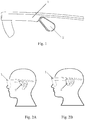
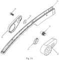
- This embodiment provides eyeglasses 1 with a bone sensing earphone 2, the overall appearance of which is shown in Figs. 1 and 2.
- Fig. 1 is a side view of the eyeglasses 1
- Fig. 2 is a side view of the eyeglasses 1 with the earphone 2 in the retracted state ( Fig. 2A ) and in the rotated state ( Fig. 2B ).
- the eyeglasses 1 include lenses, a frame, and a leg.
- the structures of the lenses and frame are structures of the conventional eyeglasses in the art. According to the different types of eyeglasses, those skilled in the art can select lenses or frame of suitable structures.
- the eyeglasses according to the present embodiment are ordinary eyeglasses or smart eyeglasses, and those skilled in the art can select corresponding structures of lenses and frame.
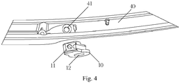
- the bone-conductive earphone 2 described above is rotatably connected to the leg 40 of eyeglasses by a connecting structure which comprises a rotating shaft bracket 10 and a connecting member.
- the bone-conductive earphone comprises a first housing 22 and a second housing 21 of bone-conductive earphone, and the connecting member comprises a rotating shaft 31 and a screw 32 (also referred to as fixing member).
- the leg 40 of eyeglasses has a connection point to the rotating shaft bracket 10.
- the connection between the rotating shaft bracket 10 and the leg 40 is configured as conventional connection in the art, such as screwing, snapping connection, plugging-in connection, inserting connection and the like.
- the connection point is located at a mounting hole 41.
- a mounting hole 11 having an internal thread is provided in the rotating shaft bracket. The screw is screwed into the mounting hole 11 through the mounting hole 41, thereby fixing the rotating shaft bracket 10 onto the leg 40.
- the rotating shaft bracket 10 is also provided with a hole 12 through which the rotating shaft 31 can pass.
- the inner side of the first housing 22 of bone-conductive earphone is provided at one end with a mounting groove 221 having a texturing structure.
- the rotating shaft 31 is also provided with a texturing structure at one end, and is inserted in the mounting groove 221 to connect the rotating shaft 31 with the first housing 22 of the bone-conductive earphone.
- the texturing structure can be formed as follows: placing the rotating shaft in a mold for injecting the housing; forming the housing by means of injection molding, wherein after the injection molding, a housing to which the rotating shaft is connected is formed, and wherein in the process of injection molding, a structure engaged with the textures of the rotating shaft end is correspondingly formed in the inner wall of the mounting groove of the housing.
- the other end of the rotating shaft 31 is passed through the hole 12 in the shaft bracket 10; on the other side, a screw 32 passes through the hole in the second housing 21 from the outer side of the second housing 21 to the inner side of the second housing 21 and is screwed into the rotating shaft 31 having internal thread, so that the second housing 21 of the bone-conductive earphone could be connected to the rotating shaft bracket.
- a washer may be provided between the screw 32 and the second housing 21 to avoid causing wear to the housing during the screwing-in of the screw.
- a gasket 50 is further disposed between the first housing 22 or the second housing 21 of the bone-conductive earphone and the rotating shaft bracket 10, and the gasket may be a metal gasket, a silicone gasket, or a rubber gasket.
- the gasket 50 may be disposed between the second housing 21 and the rotating shaft bracket 10 (as shown in Fig. 3A ); for example, the gasket 50 is disposed between the first housing 22 and the rotating shaft bracket 10, and specifically, may be disposed between the rotating shaft 31 and the first housing 22 (as shown in Fig. 5B ), and alternatively, may be disposed between the rotating shaft 31 and the rotating shaft bracket 10.
- the gasket 50 can increase the friction between the inner wall of the housing and the rotating shaft bracket, that is, increase the damping, thereby preventing the bone-conductive earphone from sliding freely on the rotating shaft.
- an adjustment by means of rotation is needed, the rotation is possible only when an external force (such as pushing by hand) is applied. In this way, the bone-conductive earphone is locked in a designated position.
- the present embodiment provides a pair of eyeglasses with a bone sensing earphone, which has a structure substantially identical to the eyeglasses of the first embodiment.
- the difference only lies in the connection between the rotating shaft 31 and the first housing 22.
- the texturing structure in the first embodiment is replaced by an integrally formed connection between the rotating shaft 31 and the first housing 22, which will not slide relative to each other. This kind of connection can be simultaneously formed by means of injection molding when the first housing 22 is injection molded.
Landscapes
- Engineering & Computer Science (AREA)
- Physics & Mathematics (AREA)
- General Engineering & Computer Science (AREA)
- Theoretical Computer Science (AREA)
- Acoustics & Sound (AREA)
- Signal Processing (AREA)
- Human Computer Interaction (AREA)
- General Physics & Mathematics (AREA)
- Manufacturing & Machinery (AREA)
- Details Of Audible-Bandwidth Transducers (AREA)
- Headphones And Earphones (AREA)
Claims (8)
- Dispositif acoustique à conduction osseuse pouvant être porté sur la tête, comprenant :un équipement pouvant être porté sur la tête qui est représenté par des lunettes (1) comprenant une branche (40),un élément acoustique à conduction osseuse, etune structure de raccordement, par le biais de laquelle l'élément acoustique à conduction osseuse est au moins raccordé en rotation à la branche de l'équipement pouvant être porté sur la tête,la structure de raccordement comprend un support d'arbre rotatif (10) et un élément de raccordement, le support d'arbre rotatif (10) étant raccordé à la branche (40),caractérisé en ce que :le support d'arbre rotatif (10) est prévu avec un trou (12) destiné à être traversé par l'élément de raccordement, etl'élément acoustique à conduction osseuse comprend au moins deux boîtiers, respectivement un premier boîtier (22) et un second boîtier (21), et l'élément de raccordement comprend un arbre rotatif (31) qui est raccordé à un côté interne du premier boîtier (22) au niveau d'une extrémité et raccordé à un côté interne du second boîtier (21) après avoir traversé le trou (12) dans le support d'arbre rotatif (10).
- Dispositif acoustique à conduction osseuse pouvant être porté sur la tête selon la revendication 1, dans lequel :
les lunettes (1) comprennent des lunettes optiques ordinaires ou des lunettes intelligentes ayant une fonction de calcul ou de communication, et dans lequel l'élément acoustique à conduction osseuse est un écouteur à conduction osseuse (2) ou un microphone à conduction osseuse ou une combinaison des deux. - Dispositif acoustique à conduction osseuse pouvant être porté sur la tête selon la revendication 2,
dans lequel le support d'arbre rotatif (10) est raccordé de manière fixe à la branche (40) au moyen d'encliquetage, rivetage, vissage, raccordement à spirale ou moulage solidaire. - Dispositif acoustique à conduction osseuse pouvant être porté sur la tête selon l'une quelconque des revendications 2 ou 3, dans lequel un joint (50) est prévu entre le premier (22) ou le second boîtier (21) et le support d'arbre rotatif (10) pour augmenter l'amortissement.
- Dispositif acoustique à conduction osseuse pouvant être porté sur la tête selon la revendication 1, dans lequel :le raccordement de l'arbre rotatif (31) au côté interne du premier boîtier (22) est sélectionné parmi une d'une première façon de raccordement ou d'une seconde façon de raccordement,dans lequel la première façon de raccordement est configurée de sorte que la une extrémité de l'arbre rotatif (31) est prévue avec une structure de texturation, le côté interne du premier boîtier (22) comprend un trou de montage (221) prévu avec une structure de texturation, et la structure de texturation de l'arbre rotatif (31) est en mise en prise avec la structure de texturation du trou de montage (221) lorsque l'arbre rotatif (31) est inséré dans le trou de montage (221) du premier boîtier (22) ; etdans lequel la seconde façon de raccordement est configurée de sorte qu'une extrémité de l'arbre rotatif (31) est formée de manière solidaire sur et raccordée au côté interne du premier boîtier (22).
- Dispositif acoustique à conduction osseuse pouvant être porté sur la tête selon la revendication 5, dans lequel :
l'arbre rotatif (31) est raccordé au côté interne du second boîtier (21) après avoir traversé le trou (12) dans le support d'arbre rotatif (10), et l'arbre rotatif (31) est raccordé au second boîtier (21) à l'aide d'un élément de fixation comprenant une vis, un boulon, et un connecteur avec une extrémité d'expansion, le raccordement comprenant le raccordement par insertion, le raccordement par encliquetage, le raccordement par enfichage, le raccordement fileté, le soudage et le rivetage ; dans lequel l'élément de fixation passe à travers le second boîtier (21) de l'extérieur vers l'intérieur et est raccordé à l'arbre de rotation (31), et une rondelle est facultativement prévue entre l'élément de fixation et le second boîtier (21). - Dispositif acoustique à conduction osseuse pouvant être porté sur la tête selon la revendication 4, dans lequel :
le joint (50) comprend un joint métallique, un joint en silicone ou un joint en caoutchouc. - Dispositif acoustique à conduction osseuse pouvant être porté sur la tête selon l'une quelconque des revendications 5 à 7, dans lequel la structure de texturation du premier boîtier mis en prise avec la structure de texturation de la une extrémité de l'arbre rotatif (31) est formée dans la paroi interne du trou de montage (221) du premier boîtier (22) en plaçant la une extrémité de l'arbre rotatif (31) dans un moule pour injecter le premier boîtier (22) et former le premier boîtier (22) au moyen du moulage par injection.
Applications Claiming Priority (1)
| Application Number | Priority Date | Filing Date | Title |
|---|---|---|---|
| CN201811105366.XA CN110944272A (zh) | 2018-09-21 | 2018-09-21 | 具有可调节骨传导声学装置的头部穿戴设备 |
Publications (2)
| Publication Number | Publication Date |
|---|---|
| EP3637794A1 EP3637794A1 (fr) | 2020-04-15 |
| EP3637794B1 true EP3637794B1 (fr) | 2020-12-02 |
Family
ID=66349388
Family Applications (1)
| Application Number | Title | Priority Date | Filing Date |
|---|---|---|---|
| EP19172012.7A Active EP3637794B1 (fr) | 2018-09-21 | 2019-04-30 | Équipement portable sur la tête comportant un dispositif acoustique à conduction osseuse réglable |
Country Status (4)
| Country | Link |
|---|---|
| EP (1) | EP3637794B1 (fr) |
| JP (1) | JP6630930B1 (fr) |
| CN (1) | CN110944272A (fr) |
| WO (1) | WO2020057111A1 (fr) |
Families Citing this family (7)
| Publication number | Priority date | Publication date | Assignee | Title |
|---|---|---|---|---|
| US12302505B2 (en) | 2019-12-10 | 2025-05-13 | Singapore University Of Technology And Design | Thin film-based microfluidic electronic device, method of forming thereof, and skin and tissue adhesive applications |
| TWI709848B (zh) * | 2020-04-28 | 2020-11-11 | 和碩聯合科技股份有限公司 | 虛擬實境頭戴式顯示裝置 |
| CN112055281B (zh) * | 2020-09-19 | 2022-10-04 | 深圳市三德大康电子有限公司 | 一种骨传导发声装置 |
| CN113986184A (zh) * | 2021-09-30 | 2022-01-28 | 歌尔光学科技有限公司 | 眼镜、眼镜的控制方法及计算机可读存储介质 |
| CN113917706B (zh) * | 2021-10-12 | 2024-04-30 | 歌尔科技有限公司 | 头戴设备 |
| CN116546356B (zh) * | 2022-01-26 | 2026-04-07 | 北京字跳网络技术有限公司 | 头戴设备的绑带组件、头戴设备 |
| CN115933199A (zh) * | 2022-12-27 | 2023-04-07 | 维沃移动通信有限公司 | 可穿戴设备 |
Family Cites Families (22)
| Publication number | Priority date | Publication date | Assignee | Title |
|---|---|---|---|---|
| WO2006089250A2 (fr) * | 2005-02-16 | 2006-08-24 | Logitech Europe S.A. | Ensemble audio personnel reversible monte derriere la tete a ecouteur pivotant |
| JP4072864B2 (ja) * | 2005-09-05 | 2008-04-09 | アイテック株式会社 | 眼鏡フレーム用モダン |
| CN1984505A (zh) * | 2005-12-16 | 2007-06-20 | 株式会社坦姆科日本 | 骨传导受话装置 |
| JP2007312050A (ja) * | 2006-05-18 | 2007-11-29 | Keiichi Uchiyama | 骨伝導ユニット装着具 |
| JP2008118401A (ja) * | 2006-11-02 | 2008-05-22 | Keiichi Uchiyama | ヘッドホン |
| KR100865959B1 (ko) * | 2007-06-18 | 2008-10-30 | 지디텍 주식회사 | 안경 부착용 이어폰장치 |
| JP5055530B2 (ja) * | 2007-09-10 | 2012-10-24 | 株式会社ビジョン・ホールディングス | 骨伝導スピーカ付き先セル及び眼鏡フレーム |
| FR2922075B1 (fr) * | 2007-10-09 | 2011-07-22 | Elno Soc Nouvelle | Casque acoustique |
| JPWO2014097744A1 (ja) * | 2012-12-17 | 2017-01-12 | 株式会社テムコジャパン | 骨導レシーバ |
| US10469935B2 (en) | 2012-12-28 | 2019-11-05 | Panasonic Intellectual Property Management Co., Ltd. | Bone conduction speaker and bone conduction headphone device |
| JP2016036094A (ja) * | 2014-08-04 | 2016-03-17 | ひかり 西河 | アイウェア用アタッチメント及びアイウェア |
| KR102174752B1 (ko) * | 2014-08-26 | 2020-11-05 | 삼성전자주식회사 | 회전장치 및 이를 포함하는 전자장치 |
| CN105011455B (zh) * | 2015-07-29 | 2018-07-31 | 广东远峰电子科技股份有限公司 | 一种基于骨传导耳机的可切换发声导向方式的骑行头盔 |
| CN205179304U (zh) | 2015-11-04 | 2016-04-20 | 东莞泉声电子有限公司 | 自由调节的人体工学骨导耳机架及其骨导耳机 |
| JP3202255U (ja) * | 2015-11-10 | 2016-01-28 | 文澤 黄 | メガネ付きイヤホン |
| CN106785344B (zh) * | 2017-01-20 | 2019-05-03 | Oppo广东移动通信有限公司 | 壳体制造方法、壳体及移动终端 |
| CN206684411U (zh) | 2017-03-14 | 2017-11-28 | 厦门金大合眼镜有限公司 | 一种骨传导眼镜 |
| CN206807709U (zh) * | 2017-05-24 | 2017-12-26 | 潍坊歌尔电子有限公司 | 一种骨传导耳机 |
| KR101853248B1 (ko) * | 2017-06-19 | 2018-04-30 | (주)시선 | 사운드 입출력 기능을 갖는 안경 |
| CN207184774U (zh) | 2017-09-28 | 2018-04-03 | 上海传英信息技术有限公司 | 骨传导耳机组件及眼镜 |
| CN107797308B (zh) | 2017-11-28 | 2019-06-14 | 苏州佑克骨传导科技有限公司 | 一种可灵活调节骨传导耳机位置的太阳眼镜 |
| CN208783085U (zh) * | 2018-09-21 | 2019-04-23 | 上海肇观电子科技有限公司 | 头戴式骨传导声学装置 |
-
2018
- 2018-09-21 CN CN201811105366.XA patent/CN110944272A/zh active Pending
-
2019
- 2019-04-11 WO PCT/CN2019/082237 patent/WO2020057111A1/fr not_active Ceased
- 2019-04-26 JP JP2019085126A patent/JP6630930B1/ja active Active
- 2019-04-30 EP EP19172012.7A patent/EP3637794B1/fr active Active
Non-Patent Citations (1)
| Title |
|---|
| None * |
Also Published As
| Publication number | Publication date |
|---|---|
| JP2020053957A (ja) | 2020-04-02 |
| JP6630930B1 (ja) | 2020-01-15 |
| CN110944272A (zh) | 2020-03-31 |
| EP3637794A1 (fr) | 2020-04-15 |
| WO2020057111A1 (fr) | 2020-03-26 |
Similar Documents
| Publication | Publication Date | Title |
|---|---|---|
| EP3637794B1 (fr) | Équipement portable sur la tête comportant un dispositif acoustique à conduction osseuse réglable | |
| US10609467B1 (en) | Head wearable equipment with adjustable bone-conductive acoustic device | |
| KR100865959B1 (ko) | 안경 부착용 이어폰장치 | |
| CN205408118U (zh) | 一种头戴显示器 | |
| US5988812A (en) | Headphone eyeglasses | |
| US8411893B2 (en) | Headphone | |
| EP2081404B1 (fr) | Écouteur | |
| JP4740317B2 (ja) | 骨伝導デバイスのメガネへの取付構造 | |
| WO2020038487A1 (fr) | Lunettes | |
| KR102358064B1 (ko) | 골전도 발성 장치 | |
| CN102428712A (zh) | 骨传导耳机 | |
| CA3183704C (fr) | Structure de retenue d'ecouteur intra-auriculaire | |
| CN208783085U (zh) | 头戴式骨传导声学装置 | |
| CN211061803U (zh) | 智能眼镜 | |
| JP2010252132A (ja) | ステレオイヤホン | |
| CN210579163U (zh) | 一种头戴耳机 | |
| CN110018579A (zh) | 骨传导眼镜 | |
| CN218068483U (zh) | 耳机组件、眼镜架及眼镜 | |
| CN207340129U (zh) | 一种vr头戴设备 | |
| CN219087272U (zh) | 一种耳机 | |
| US20250024190A1 (en) | Earphones | |
| CN222706607U (zh) | 耳机 | |
| CN111083594B (zh) | 一种头戴耳机 | |
| CN207074316U (zh) | 具有蓝牙耳机的眼镜 | |
| JPH04177997A (ja) | 耳装着型送受話器 |
Legal Events
| Date | Code | Title | Description |
|---|---|---|---|
| STAA | Information on the status of an ep patent application or granted ep patent |
Free format text: STATUS: EXAMINATION IS IN PROGRESS |
|
| PUAI | Public reference made under article 153(3) epc to a published international application that has entered the european phase |
Free format text: ORIGINAL CODE: 0009012 |
|
| 17P | Request for examination filed |
Effective date: 20190430 |
|
| AK | Designated contracting states |
Kind code of ref document: A1 Designated state(s): AL AT BE BG CH CY CZ DE DK EE ES FI FR GB GR HR HU IE IS IT LI LT LU LV MC MK MT NL NO PL PT RO RS SE SI SK SM TR |
|
| AX | Request for extension of the european patent |
Extension state: BA ME |
|
| GRAP | Despatch of communication of intention to grant a patent |
Free format text: ORIGINAL CODE: EPIDOSNIGR1 |
|
| STAA | Information on the status of an ep patent application or granted ep patent |
Free format text: STATUS: GRANT OF PATENT IS INTENDED |
|
| RIC1 | Information provided on ipc code assigned before grant |
Ipc: H04R 5/033 20060101AFI20200612BHEP Ipc: G02B 27/01 20060101ALN20200612BHEP |
|
| INTG | Intention to grant announced |
Effective date: 20200630 |
|
| GRAS | Grant fee paid |
Free format text: ORIGINAL CODE: EPIDOSNIGR3 |
|
| GRAA | (expected) grant |
Free format text: ORIGINAL CODE: 0009210 |
|
| STAA | Information on the status of an ep patent application or granted ep patent |
Free format text: STATUS: THE PATENT HAS BEEN GRANTED |
|
| AK | Designated contracting states |
Kind code of ref document: B1 Designated state(s): AL AT BE BG CH CY CZ DE DK EE ES FI FR GB GR HR HU IE IS IT LI LT LU LV MC MK MT NL NO PL PT RO RS SE SI SK SM TR |
|
| REG | Reference to a national code |
Ref country code: GB Ref legal event code: FG4D |
|
| REG | Reference to a national code |
Ref country code: CH Ref legal event code: EP Ref country code: AT Ref legal event code: REF Ref document number: 1342259 Country of ref document: AT Kind code of ref document: T Effective date: 20201215 |
|
| REG | Reference to a national code |
Ref country code: IE Ref legal event code: FG4D |
|
| REG | Reference to a national code |
Ref country code: DE Ref legal event code: R096 Ref document number: 602019001551 Country of ref document: DE |
|
| PG25 | Lapsed in a contracting state [announced via postgrant information from national office to epo] |
Ref country code: RS Free format text: LAPSE BECAUSE OF FAILURE TO SUBMIT A TRANSLATION OF THE DESCRIPTION OR TO PAY THE FEE WITHIN THE PRESCRIBED TIME-LIMIT Effective date: 20201202 Ref country code: FI Free format text: LAPSE BECAUSE OF FAILURE TO SUBMIT A TRANSLATION OF THE DESCRIPTION OR TO PAY THE FEE WITHIN THE PRESCRIBED TIME-LIMIT Effective date: 20201202 Ref country code: GR Free format text: LAPSE BECAUSE OF FAILURE TO SUBMIT A TRANSLATION OF THE DESCRIPTION OR TO PAY THE FEE WITHIN THE PRESCRIBED TIME-LIMIT Effective date: 20210303 Ref country code: NO Free format text: LAPSE BECAUSE OF FAILURE TO SUBMIT A TRANSLATION OF THE DESCRIPTION OR TO PAY THE FEE WITHIN THE PRESCRIBED TIME-LIMIT Effective date: 20210302 |
|
| REG | Reference to a national code |
Ref country code: NL Ref legal event code: MP Effective date: 20201202 |
|
| REG | Reference to a national code |
Ref country code: AT Ref legal event code: MK05 Ref document number: 1342259 Country of ref document: AT Kind code of ref document: T Effective date: 20201202 |
|
| PG25 | Lapsed in a contracting state [announced via postgrant information from national office to epo] |
Ref country code: SE Free format text: LAPSE BECAUSE OF FAILURE TO SUBMIT A TRANSLATION OF THE DESCRIPTION OR TO PAY THE FEE WITHIN THE PRESCRIBED TIME-LIMIT Effective date: 20201202 Ref country code: PL Free format text: LAPSE BECAUSE OF FAILURE TO SUBMIT A TRANSLATION OF THE DESCRIPTION OR TO PAY THE FEE WITHIN THE PRESCRIBED TIME-LIMIT Effective date: 20201202 Ref country code: LV Free format text: LAPSE BECAUSE OF FAILURE TO SUBMIT A TRANSLATION OF THE DESCRIPTION OR TO PAY THE FEE WITHIN THE PRESCRIBED TIME-LIMIT Effective date: 20201202 Ref country code: BG Free format text: LAPSE BECAUSE OF FAILURE TO SUBMIT A TRANSLATION OF THE DESCRIPTION OR TO PAY THE FEE WITHIN THE PRESCRIBED TIME-LIMIT Effective date: 20210302 |
|
| PG25 | Lapsed in a contracting state [announced via postgrant information from national office to epo] |
Ref country code: HR Free format text: LAPSE BECAUSE OF FAILURE TO SUBMIT A TRANSLATION OF THE DESCRIPTION OR TO PAY THE FEE WITHIN THE PRESCRIBED TIME-LIMIT Effective date: 20201202 Ref country code: NL Free format text: LAPSE BECAUSE OF FAILURE TO SUBMIT A TRANSLATION OF THE DESCRIPTION OR TO PAY THE FEE WITHIN THE PRESCRIBED TIME-LIMIT Effective date: 20201202 |
|
| REG | Reference to a national code |
Ref country code: LT Ref legal event code: MG9D |
|
| PG25 | Lapsed in a contracting state [announced via postgrant information from national office to epo] |
Ref country code: CZ Free format text: LAPSE BECAUSE OF FAILURE TO SUBMIT A TRANSLATION OF THE DESCRIPTION OR TO PAY THE FEE WITHIN THE PRESCRIBED TIME-LIMIT Effective date: 20201202 Ref country code: SK Free format text: LAPSE BECAUSE OF FAILURE TO SUBMIT A TRANSLATION OF THE DESCRIPTION OR TO PAY THE FEE WITHIN THE PRESCRIBED TIME-LIMIT Effective date: 20201202 Ref country code: SM Free format text: LAPSE BECAUSE OF FAILURE TO SUBMIT A TRANSLATION OF THE DESCRIPTION OR TO PAY THE FEE WITHIN THE PRESCRIBED TIME-LIMIT Effective date: 20201202 Ref country code: EE Free format text: LAPSE BECAUSE OF FAILURE TO SUBMIT A TRANSLATION OF THE DESCRIPTION OR TO PAY THE FEE WITHIN THE PRESCRIBED TIME-LIMIT Effective date: 20201202 Ref country code: PT Free format text: LAPSE BECAUSE OF FAILURE TO SUBMIT A TRANSLATION OF THE DESCRIPTION OR TO PAY THE FEE WITHIN THE PRESCRIBED TIME-LIMIT Effective date: 20210405 Ref country code: RO Free format text: LAPSE BECAUSE OF FAILURE TO SUBMIT A TRANSLATION OF THE DESCRIPTION OR TO PAY THE FEE WITHIN THE PRESCRIBED TIME-LIMIT Effective date: 20201202 Ref country code: LT Free format text: LAPSE BECAUSE OF FAILURE TO SUBMIT A TRANSLATION OF THE DESCRIPTION OR TO PAY THE FEE WITHIN THE PRESCRIBED TIME-LIMIT Effective date: 20201202 |
|
| PG25 | Lapsed in a contracting state [announced via postgrant information from national office to epo] |
Ref country code: AT Free format text: LAPSE BECAUSE OF FAILURE TO SUBMIT A TRANSLATION OF THE DESCRIPTION OR TO PAY THE FEE WITHIN THE PRESCRIBED TIME-LIMIT Effective date: 20201202 |
|
| REG | Reference to a national code |
Ref country code: DE Ref legal event code: R097 Ref document number: 602019001551 Country of ref document: DE |
|
| PG25 | Lapsed in a contracting state [announced via postgrant information from national office to epo] |
Ref country code: IS Free format text: LAPSE BECAUSE OF FAILURE TO SUBMIT A TRANSLATION OF THE DESCRIPTION OR TO PAY THE FEE WITHIN THE PRESCRIBED TIME-LIMIT Effective date: 20210402 |
|
| PLBE | No opposition filed within time limit |
Free format text: ORIGINAL CODE: 0009261 |
|
| STAA | Information on the status of an ep patent application or granted ep patent |
Free format text: STATUS: NO OPPOSITION FILED WITHIN TIME LIMIT |
|
| PG25 | Lapsed in a contracting state [announced via postgrant information from national office to epo] |
Ref country code: IT Free format text: LAPSE BECAUSE OF FAILURE TO SUBMIT A TRANSLATION OF THE DESCRIPTION OR TO PAY THE FEE WITHIN THE PRESCRIBED TIME-LIMIT Effective date: 20201202 Ref country code: AL Free format text: LAPSE BECAUSE OF FAILURE TO SUBMIT A TRANSLATION OF THE DESCRIPTION OR TO PAY THE FEE WITHIN THE PRESCRIBED TIME-LIMIT Effective date: 20201202 |
|
| 26N | No opposition filed |
Effective date: 20210903 |
|
| PG25 | Lapsed in a contracting state [announced via postgrant information from national office to epo] |
Ref country code: MC Free format text: LAPSE BECAUSE OF FAILURE TO SUBMIT A TRANSLATION OF THE DESCRIPTION OR TO PAY THE FEE WITHIN THE PRESCRIBED TIME-LIMIT Effective date: 20201202 Ref country code: DK Free format text: LAPSE BECAUSE OF FAILURE TO SUBMIT A TRANSLATION OF THE DESCRIPTION OR TO PAY THE FEE WITHIN THE PRESCRIBED TIME-LIMIT Effective date: 20201202 Ref country code: SI Free format text: LAPSE BECAUSE OF FAILURE TO SUBMIT A TRANSLATION OF THE DESCRIPTION OR TO PAY THE FEE WITHIN THE PRESCRIBED TIME-LIMIT Effective date: 20201202 |
|
| PG25 | Lapsed in a contracting state [announced via postgrant information from national office to epo] |
Ref country code: LU Free format text: LAPSE BECAUSE OF NON-PAYMENT OF DUE FEES Effective date: 20210430 |
|
| REG | Reference to a national code |
Ref country code: BE Ref legal event code: MM Effective date: 20210430 |
|
| PG25 | Lapsed in a contracting state [announced via postgrant information from national office to epo] |
Ref country code: ES Free format text: LAPSE BECAUSE OF FAILURE TO SUBMIT A TRANSLATION OF THE DESCRIPTION OR TO PAY THE FEE WITHIN THE PRESCRIBED TIME-LIMIT Effective date: 20201202 |
|
| PG25 | Lapsed in a contracting state [announced via postgrant information from national office to epo] |
Ref country code: IE Free format text: LAPSE BECAUSE OF NON-PAYMENT OF DUE FEES Effective date: 20210430 |
|
| PG25 | Lapsed in a contracting state [announced via postgrant information from national office to epo] |
Ref country code: IS Free format text: LAPSE BECAUSE OF FAILURE TO SUBMIT A TRANSLATION OF THE DESCRIPTION OR TO PAY THE FEE WITHIN THE PRESCRIBED TIME-LIMIT Effective date: 20210402 |
|
| PG25 | Lapsed in a contracting state [announced via postgrant information from national office to epo] |
Ref country code: BE Free format text: LAPSE BECAUSE OF NON-PAYMENT OF DUE FEES Effective date: 20210430 |
|
| REG | Reference to a national code |
Ref country code: CH Ref legal event code: PL |
|
| PG25 | Lapsed in a contracting state [announced via postgrant information from national office to epo] |
Ref country code: LI Free format text: LAPSE BECAUSE OF NON-PAYMENT OF DUE FEES Effective date: 20220430 Ref country code: CH Free format text: LAPSE BECAUSE OF NON-PAYMENT OF DUE FEES Effective date: 20220430 |
|
| PG25 | Lapsed in a contracting state [announced via postgrant information from national office to epo] |
Ref country code: CY Free format text: LAPSE BECAUSE OF FAILURE TO SUBMIT A TRANSLATION OF THE DESCRIPTION OR TO PAY THE FEE WITHIN THE PRESCRIBED TIME-LIMIT Effective date: 20201202 |
|
| PG25 | Lapsed in a contracting state [announced via postgrant information from national office to epo] |
Ref country code: HU Free format text: LAPSE BECAUSE OF FAILURE TO SUBMIT A TRANSLATION OF THE DESCRIPTION OR TO PAY THE FEE WITHIN THE PRESCRIBED TIME-LIMIT; INVALID AB INITIO Effective date: 20190430 |
|
| PG25 | Lapsed in a contracting state [announced via postgrant information from national office to epo] |
Ref country code: MK Free format text: LAPSE BECAUSE OF FAILURE TO SUBMIT A TRANSLATION OF THE DESCRIPTION OR TO PAY THE FEE WITHIN THE PRESCRIBED TIME-LIMIT Effective date: 20201202 |
|
| PG25 | Lapsed in a contracting state [announced via postgrant information from national office to epo] |
Ref country code: TR Free format text: LAPSE BECAUSE OF FAILURE TO SUBMIT A TRANSLATION OF THE DESCRIPTION OR TO PAY THE FEE WITHIN THE PRESCRIBED TIME-LIMIT Effective date: 20201202 |
|
| PG25 | Lapsed in a contracting state [announced via postgrant information from national office to epo] |
Ref country code: MT Free format text: LAPSE BECAUSE OF FAILURE TO SUBMIT A TRANSLATION OF THE DESCRIPTION OR TO PAY THE FEE WITHIN THE PRESCRIBED TIME-LIMIT Effective date: 20201202 |
|
| PGFP | Annual fee paid to national office [announced via postgrant information from national office to epo] |
Ref country code: DE Payment date: 20250428 Year of fee payment: 7 |
|
| PGFP | Annual fee paid to national office [announced via postgrant information from national office to epo] |
Ref country code: GB Payment date: 20260326 Year of fee payment: 8 |
|
| PGFP | Annual fee paid to national office [announced via postgrant information from national office to epo] |
Ref country code: FR Payment date: 20260331 Year of fee payment: 8 |