EP3637934B1 - Procédé et appareil à utiliser dans une configuration de ressources - Google Patents
Procédé et appareil à utiliser dans une configuration de ressources Download PDFInfo
- Publication number
- EP3637934B1 EP3637934B1 EP18795263.5A EP18795263A EP3637934B1 EP 3637934 B1 EP3637934 B1 EP 3637934B1 EP 18795263 A EP18795263 A EP 18795263A EP 3637934 B1 EP3637934 B1 EP 3637934B1
- Authority
- EP
- European Patent Office
- Prior art keywords
- random access
- downlink signal
- configuration information
- downlink
- resource
- Prior art date
- Legal status (The legal status is an assumption and is not a legal conclusion. Google has not performed a legal analysis and makes no representation as to the accuracy of the status listed.)
- Active
Links
Images






Classifications
-
- H—ELECTRICITY
- H04—ELECTRIC COMMUNICATION TECHNIQUE
- H04L—TRANSMISSION OF DIGITAL INFORMATION, e.g. TELEGRAPHIC COMMUNICATION
- H04L5/00—Arrangements affording multiple use of the transmission path
- H04L5/0001—Arrangements for dividing the transmission path
- H04L5/0003—Two-dimensional division
- H04L5/0005—Time-frequency
- H04L5/0007—Time-frequency the frequencies being orthogonal, e.g. OFDM(A) or DMT
-
- H—ELECTRICITY
- H04—ELECTRIC COMMUNICATION TECHNIQUE
- H04W—WIRELESS COMMUNICATION NETWORKS
- H04W74/00—Wireless channel access
- H04W74/002—Transmission of channel access control information
-
- H—ELECTRICITY
- H04—ELECTRIC COMMUNICATION TECHNIQUE
- H04L—TRANSMISSION OF DIGITAL INFORMATION, e.g. TELEGRAPHIC COMMUNICATION
- H04L47/00—Traffic control in data switching networks
- H04L47/70—Admission control; Resource allocation
- H04L47/72—Admission control; Resource allocation using reservation actions during connection setup
- H04L47/726—Reserving resources in multiple paths to be used simultaneously
-
- H—ELECTRICITY
- H04—ELECTRIC COMMUNICATION TECHNIQUE
- H04L—TRANSMISSION OF DIGITAL INFORMATION, e.g. TELEGRAPHIC COMMUNICATION
- H04L47/00—Traffic control in data switching networks
- H04L47/70—Admission control; Resource allocation
- H04L47/82—Miscellaneous aspects
- H04L47/824—Applicable to portable or mobile terminals
-
- H—ELECTRICITY
- H04—ELECTRIC COMMUNICATION TECHNIQUE
- H04L—TRANSMISSION OF DIGITAL INFORMATION, e.g. TELEGRAPHIC COMMUNICATION
- H04L5/00—Arrangements affording multiple use of the transmission path
- H04L5/003—Arrangements for allocating sub-channels of the transmission path
- H04L5/0048—Allocation of pilot signals, i.e. of signals known to the receiver
-
- H—ELECTRICITY
- H04—ELECTRIC COMMUNICATION TECHNIQUE
- H04L—TRANSMISSION OF DIGITAL INFORMATION, e.g. TELEGRAPHIC COMMUNICATION
- H04L5/00—Arrangements affording multiple use of the transmission path
- H04L5/003—Arrangements for allocating sub-channels of the transmission path
- H04L5/0048—Allocation of pilot signals, i.e. of signals known to the receiver
- H04L5/005—Allocation of pilot signals, i.e. of signals known to the receiver of common pilots, i.e. pilots destined for multiple users or terminals
-
- H—ELECTRICITY
- H04—ELECTRIC COMMUNICATION TECHNIQUE
- H04L—TRANSMISSION OF DIGITAL INFORMATION, e.g. TELEGRAPHIC COMMUNICATION
- H04L5/00—Arrangements affording multiple use of the transmission path
- H04L5/003—Arrangements for allocating sub-channels of the transmission path
- H04L5/0053—Allocation of signalling, i.e. of overhead other than pilot signals
-
- H—ELECTRICITY
- H04—ELECTRIC COMMUNICATION TECHNIQUE
- H04L—TRANSMISSION OF DIGITAL INFORMATION, e.g. TELEGRAPHIC COMMUNICATION
- H04L5/00—Arrangements affording multiple use of the transmission path
- H04L5/003—Arrangements for allocating sub-channels of the transmission path
- H04L5/0078—Timing of allocation
- H04L5/0082—Timing of allocation at predetermined intervals
-
- H—ELECTRICITY
- H04—ELECTRIC COMMUNICATION TECHNIQUE
- H04W—WIRELESS COMMUNICATION NETWORKS
- H04W56/00—Synchronisation arrangements
- H04W56/004—Synchronisation arrangements compensating for timing error of reception due to propagation delay
- H04W56/0045—Synchronisation arrangements compensating for timing error of reception due to propagation delay compensating for timing error by altering transmission time
-
- H—ELECTRICITY
- H04—ELECTRIC COMMUNICATION TECHNIQUE
- H04W—WIRELESS COMMUNICATION NETWORKS
- H04W72/00—Local resource management
- H04W72/04—Wireless resource allocation
-
- H—ELECTRICITY
- H04—ELECTRIC COMMUNICATION TECHNIQUE
- H04W—WIRELESS COMMUNICATION NETWORKS
- H04W72/00—Local resource management
- H04W72/04—Wireless resource allocation
- H04W72/044—Wireless resource allocation based on the type of the allocated resource
- H04W72/046—Wireless resource allocation based on the type of the allocated resource the resource being in the space domain, e.g. beams
-
- H—ELECTRICITY
- H04—ELECTRIC COMMUNICATION TECHNIQUE
- H04W—WIRELESS COMMUNICATION NETWORKS
- H04W74/00—Wireless channel access
- H04W74/002—Transmission of channel access control information
- H04W74/006—Transmission of channel access control information in the downlink, i.e. towards the terminal
-
- H—ELECTRICITY
- H04—ELECTRIC COMMUNICATION TECHNIQUE
- H04W—WIRELESS COMMUNICATION NETWORKS
- H04W74/00—Wireless channel access
- H04W74/08—Non-scheduled access, e.g. ALOHA
-
- H—ELECTRICITY
- H04—ELECTRIC COMMUNICATION TECHNIQUE
- H04W—WIRELESS COMMUNICATION NETWORKS
- H04W74/00—Wireless channel access
- H04W74/08—Non-scheduled access, e.g. ALOHA
- H04W74/0833—Random access procedures, e.g. with 4-step access
Definitions
- the present invention relates to the field of communications technologies, and in particular, to a resource configuration method and an apparatus.
- downlink synchronization and uplink synchronization need to be performed before a network device and a terminal device communicate with each other.
- the network device sends a downlink synchronization signal using a plurality of transmit beams, and the terminal device receives and detects the downlink synchronization signal using one or more receive beams, to obtain an optimum downlink transmit beam and receive beam pair, a time, and system information.
- Uplink synchronization is implemented by using a random access process. The terminal device first sends a random access signal. Then the network device detects the random access signal to obtain an optimum uplink transmit beam and receive beam pair, an uplink time, and the like. Finally, uplink synchronization between the network device and the terminal device is implemented.
- LTE long term evolution
- a network device uses a same beam to perform sending and receiving with a terminal device within a coverage area of the network device.
- a random access resource configuration method for LTE is inapplicable to the multi-beam network.
- EP 3 131 343 A1 discloses a random access device and method in which a user equipment determines a PRACH resource based on a configuration parameter in a notification message received from a base station.
- US 2016/183225 A1 and WO 2007052971 A1 likewise disclose solutions for performing a random access procedure with a device based on information received form a base station or network.
- WO 2016/195346 A1 discloses a terminal comprising: a reception unit for receiving pilot signals; a processor for measuring reception strength of the pilot signals, determining beam-based random access participation on the basis of the measured reception strength, and controlling for an attempt for a beam-based random access if a random access is beam-based random access participation and an attempt for normal random access if not; and a transmission unit for transmitting a random access signal on the basis of the random access attempt.
- FIG. 1 is a schematic architectural diagram of a communications system according to an embodiment of the present invention.
- the communications system includes a base station and a terminal device.
- the communications system may be a global system for mobile communications (GSM), a code division multiple access (CDMA) system, a wideband code division multiple access (WCDMA) system, a worldwide interoperability for microwave access (WiMAX) system, a long term evolution (LTE) system, a 5G communications system (for example, a new radio (NR) system, a communications system integrating a plurality of communications technologies (for example, a communications system integrating an LTE technology and an NR technology), or a subsequent evolved communications system.
- GSM global system for mobile communications
- CDMA code division multiple access
- WCDMA wideband code division multiple access
- WiMAX worldwide interoperability for microwave access
- LTE long term evolution
- 5G communications system for example, a new radio (NR) system
- a communications system integrating a plurality of communications technologies for
- a terminal device in this application is a device with a wireless communication function, and may be a handheld device, an in-vehicle device, a wearable device, or a computing device with a wireless communication function, or another processing device connected to a wireless modem.
- the terminal device may have different names.
- the terminal device may be user equipment (UE), an access terminal, a subscriber unit, a subscriber station, a mobile station, a mobile console, a remote station, a remote terminal, a mobile device, a user terminal, a terminal, a wireless communications device, a user agent or a user apparatus, a cellular phone, a cordless phone, a session initiation protocol (SIP) phone, a wireless local loop (WLL) station, a personal digital assistant (PDA), or a terminal device in a 5G network or a future evolved network.
- UE user equipment
- an access terminal UE
- UE user equipment
- UE access terminal
- a subscriber unit a subscriber station
- a mobile station a mobile console
- a remote station a remote terminal
- a mobile device a user terminal, a terminal, a wireless communications device, a user agent or a user apparatus, a cellular phone, a cordless phone, a session initiation protocol (SIP) phone, a wireless local
- a network device in this application is a device deployed in a wireless access network to provide a wireless communications function.
- the network device includes but is not limited to a base station (for example, a BTS (BTS), a NodeB (NB), an evolved NodeB (eNB or eNodeB), a transmission reception point or transmission point (TRP, or TP) or a next generation NodeB (gNB) in an NR system, or a base station or a network device in a future communications network), a relay node, an access point, an in-vehicle device, a wearable device, a wireless fidelity (Wi-Fi) station, a wireless backhaul node, a small cell, or a micro base station.
- a base station for example, a BTS (BTS), a NodeB (NB), an evolved NodeB (eNB or eNodeB), a transmission reception point or transmission point (TRP, or TP) or a next generation NodeB (gNB) in
- a base station 102 may include a plurality of antenna groups.
- Each antenna group may include one or more antennas.
- one antenna group may include an antenna 104 and an antenna 106, and another antenna group may include an antenna 108 and an antenna 110.
- an additional group may be further included, and the additional group may include an antenna 112 and an antenna 114.
- different antenna groups may be combined to form different antenna panels (panel). For example, one of the antenna groups forms one beam pointing to one direction; and another antenna group forms another beam pointing to another direction.
- more antennas may be required. Therefore, different quantities of antennas may be configured for the additional group according to different device capabilities. For example, in FIG.
- the base station 102 may additionally include a transmitter chain and a receiver chain.
- a transmitter chain and a receiver chain A person of ordinary skill in the art may understand that both the transmitter chain and the receiver chain may include a plurality of components related to signal sending and receiving, for example, a processor, a modulator, a multiplexer, a demodulator, a demultiplexer, or an antenna.
- the base station 102 may communicate with one or more terminal devices, for example, communicating with a terminal device 116 and a terminal device 122. However, it may be understood that the base station 102 may communicate with any quantity of terminal devices similar to the terminal device 116 or 122. As shown in FIG. 1 , the terminal device 116 communicates with the antenna 112 and the antenna 114. The antenna 112 and the antenna 114 send information to the terminal device 116 through a forward link 118, and receive information from the terminal device 116 through a reverse link 120. In addition, the terminal device 122 communicates with the antenna 104 and the antenna 106.
- the antenna 104 and the antenna 106 send information to the terminal device 122 through a forward link 124, and receive information from the terminal device 122 through a reverse link 126.
- a frequency division duplex (FDD) system for example, a frequency band different from that used for the reverse link 120 may be used for the forward link 118, and a frequency band different from that used for the reverse link 126 may be used for the forward link 124.
- FDD frequency division duplex
- TDD time division duplex
- the forward link 118 and the reverse link 120 may share a frequency band
- the forward link 124 and the reverse link 126 may share a frequency band.
- An area covered by each group of antennas designed for communication and/or an area covered by transmission of each group of antennas are/is referred to as a sector of the base station 102.
- an antenna group may be designed to communicate with a terminal device in a sector of an area covered by the base station 102.
- signal-to-noise ratios of the forward link 118 and the forward link 124 may be increased through beamforming on transmit antennas of the base station 102.
- the base station 102, and the terminal device 116 or the terminal device 122 each may be a wireless communications sending apparatus and/or a wireless communications receiving apparatus.
- the wireless communication sending apparatus may encode the data for transmission.
- the wireless communication sending apparatus may obtain (for example, generating, receiving from another communications apparatus, or storing in a memory), a specific quantity of data bits that are to be sent to the wireless communication receiving apparatus through a channel.
- Such data bits may be included in a transport block or a plurality of transport blocks of the data, and the transport block may be segmented to generate a plurality of code blocks.
- a next generation mobile communications system for example, a new radio (NR) communications system
- the network device uses a plurality of transmit beams to implement full coverage of downlink data transmission.
- the network device uses a plurality of receive beams to implement full coverage of uplink data transmission.
- an uplink/downlink signal may be a synchronization signal block (SS block).
- SS block synchronization signal block
- One downlink signal corresponds to one transmit beam.
- the network device associates each downlink signal with an independent random access resource and an independent random access preamble.
- a plurality of uplink/downlink signals form one uplink/downlink signal group, or referred to as an uplink/downlink signal burst (in a specific example, the uplink/downlink signal burst may be an SS burst).
- a plurality of uplink/downlink signal groups implementing full coverage are referred to as one uplink/downlink signal burst set (in a specific example, the uplink/downlink signal burst set may be an SS burst set).
- FIG. 3 is a schematic diagram of loads on different transmit beams and different receive beams. There are a larger quantity of users on some beams (for example, a transmit beam 1 and a receive beam 1 in FIG. 3 ), and there are a smaller quantity of users on some beams (for example, a transmit beam 2 and a receive beam 2 in FIG. 3 ). Therefore, different quantities of random access resources need to be associated with different loads on the beams.
- transmit beams and receive beams of the network device do not exactly correspond to each other.
- a coverage area of one transmit beam of the network device may be covered by a plurality of receive beams. Therefore, flexible resource configuration is required to efficiently support random access.
- the embodiments of the present invention provide a specific solution.
- the embodiments of the present invention provide a resource configuration method and an apparatus, to provide a simple resource configuration solution for a multi-beam network, thereby implementing random access associated with a downlink signal in the multi-beam network.
- FIG. 5 is a schematic interactive diagram of a resource configuration method according to an embodiment of the present invention. The method includes the following steps.
- a terminal device obtains configuration information, where the configuration information includes at least one piece of the following information: random access configuration information and downlink signal parameter information.
- the terminal device accesses a network device based on the configuration information.
- the network device receives an access request of the terminal device.
- the configuration information may be sent using system information (SI).
- SI system information
- S102 includes:
- the network device receives an access request of the terminal device specifically includes the following: The network device receives the random access preamble that is sent by the terminal device on the random access resource associated with the downlink signal.
- the random access configuration information is specifically a configuration of random access resources.
- the random access resource may also be understood as a random access occasion (RACH occasion/RACH transmission occasion/RACH opportunity RACH chance) of one or more random access channels (RACH).
- RACH occasion/RACH transmission occasion/RACH opportunity RACH chance of one or more random access channels (RACH).
- One random access preamble format may be sent on one random access occasion, one random access burst RACH burst may include at least one random access occasion, and one random access burst set RACH burst set may include at least one random access burst.
- One downlink signal burst set is associated with one random access burst set, one downlink signal burst is associated with one random access burst, and the random access burst set is a random access time period. Detailed descriptions are provided below.
- the configuration information may be prestored in the terminal device or a third-party storage device (the third-party storage device is a device other than the terminal device and the network device).
- the terminal device obtains the configuration information from a memory of the terminal device or the third-party storage device; or the terminal device may receive the configuration information sent from the network device.
- the network device sends a plurality of downlink signals to perform downlink synchronization, and each downlink signal is associated with an independent random access resource. Therefore, the configuration information may further include parameter information of the plurality of downlink signals. Detailed descriptions are also provided below.
- a structure of a random access resource may be as follows.
- FIG. 6 is a schematic diagram of a frame structure.
- a frame has a length of 10 ms, one subframe has a time length of 1 ms, and one subframe may include at least two slots (slot).
- FIG. 7 is a schematic structural diagram of random access resources.
- M contiguous time units which may be subframes, slots, mini-slots (mini slot), or orthogonal frequency division multiplexing (OFDM) symbols
- K random access resources there are K random access resources, and each random access resource (or RACH occasion) may be used by the terminal device to initiate one time of random access.
- Quantities of random access resources may be the same at different frequencies (in FIG. 7 , there are K random access resources at each of frequencies 1 to F).
- quantities of random access resources may be different at different frequencies. For example, if correspondingly used random access preamble formats are different, corresponding resource time lengths are different, and therefore different quantities of random access resources are accommodated in a same time.
- FIG. 8a is a schematic structural diagram of random access preambles on a single random access resource.
- a slot or subframe includes downlink data, uplink data, a guard time, and a random access resource.
- the random access resource further includes K random access preambles (or random access preamble formats).
- the downlink data and the uplink data each may include 0 to 12 OFDM symbols.
- a time length of a guard time 1 may be 0.
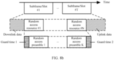
- FIG. 8b is a schematic structural diagram of random access preambles on N random access resources.
- the N random access resources include K random access preambles, and downlink data and uplink data each may include 0 to 12 OFDM symbols.
- a time length of a guard time 1 may be 0.
- T 1 to 64
- N 1 to 64
- K N*(1 to 14)
- a length of a cyclic prefix of the random access preamble is 32*(1 to 512) sampling Ts.
- the random access configuration (RACH configuration/allocation) information includes a start time, duration, and an end time of random access.
- a time unit may be at least one of the following: a subframe, a slot, a mini-slot, an OFDM symbol, or and a random access resource index.
- the start time represents a start location of one or more random access resources in a time period.
- the duration represents a time in which one or more random access resources are located, and the end time represents an end location of one or more random access resources a time period.
- a slot number may be taken from 1 to K, and K is an integer.
- K represents a total quantity of slots in one subframe, and a value of K is 2 to 64.
- a quantity of contiguous subframes on a physical random access channel (PRACH) may be 1 to 4.
- PRACH physical random access channel
- this parameter may be obtained based on a preamble format without being indicated.
- a quantity of contiguous slots on the PRACH may be 1 to K, and K is an integer.
- K represents a total quantity of slots in one subframe, and a value of K is 2 to 64.
- This parameter may also be obtained based on a preamble format without being indicated; or this parameter may be fixedly any one of 2, 4, 8, 16, and 32.
- the random access configuration information includes at least one of the following: a PRACH configuration index, a preamble format, a system frame number (SFN), a subframe number, a quantity of random access resources, a frequency quantity, a frequency start location, a frequency offset, a timing advance, random access preamble grouping information, and a subcarrier spacing.
- the system frame number may be a value that makes Mod(SFN, N) a constant.
- N is 2, and an odd-numbered frame and an even-numbered frame may be indicated.
- N is 4 to 16, and N system frame locations may be specified.
- the quantity of random access resources is a quantity of random access resources included in a subframe or a slot. This parameter may not need to be indicated, for example, the quantity is fixed; or this parameter is obtained based on a preamble format, a quantity of contiguous subframes, or a quantity of contiguous slots.
- This parameter may not need to be indicated, either.
- the parameter is fixedly 1.
- the frequency start location may be any nonnegative integer, and represents a frequency location of the first resource block in which a random access resource is located at a frequency.
- the frequency offset may be any nonnegative integer, and a specific frequency location of the random access resource may be determined based on the frequency offset and the frequency start location. This parameter may not need to be indicated, either.
- the offset is fixedly 0.
- the timing advance may be any nonnegative integer, and represents an advance of time relative to a subframe, a slot, a mini-slot, or an OFDM symbol during random access transmission. This parameter may not need to be indicated, either. For example, the timing advance is fixedly 0.
- the timing advance is fixedly 0.
- the random access configuration information may further include at least one of the following: a quantity of downlink data symbols and a quantity of uplink data symbols.
- a quantity of downlink data symbols and a quantity of uplink data symbols on a PRACH resource each may be 0 to 13 OFDM symbols. This parameter may not need to be indicated, either. For example, the quantity is fixed, or this parameter is obtained based on a preamble format, a quantity of contiguous subframes, or a quantity of contiguous slots.
- the random access configuration information may include the following possible cases, as shown in Table 1 to Table 3.
- indexes of a subframe, a slot, a mini-slot, an OFDM symbol, and a random access resource may be respectively numbers of the subframe, the slot, the mini-slot, the OFDM symbol, and the random access resource.
- the random access configuration information may include the information in at least one of Table 1 to Table 3.
- the quantity of random access resources may be obtained based on a preamble format, the quantity of contiguous subframes, the quantity of contiguous slots, a quantity of contiguous mini-slots, and the quantity of contiguous OFDM symbols. Therefore, the information, namely, the quantity of random access resources, may not be mandatory.
- the subframe number and the quantity of contiguous subframes, a slot number and the quantity of contiguous slots, a mini-slot number and a quantity of contiguous mini-slots, and the OFDM symbol and the quantity of contiguous OFDM symbols may be respectively represented by a subframe number set, a slot number set, a mini-slot number set, and an OFDM symbol number set.
- an uplink/downlink configuration index parameter may be further added to the random access configuration information, and a subframe number-related configuration parameter is a tuple.
- the terminal device needs to determine a location of an uplink subframe in a system frame and a specific subframe number based on an uplink/downlink configuration and a subframe number-related configuration. The reason for using such a configuration is that the location of the uplink subframe may change, and therefore it is only feasible to use a parameter to indicate a relative location of the uplink subframe during random access, and a specific subframe number is determined based on the uplink subframe configuration and the relative location.
- the downlink signal parameter information includes at least one piece of the following information: a quantity of downlink signal bursts in a downlink signal burst set and a quantity of downlink signals in each downlink signal burst, as described in Table 4.
- a total quantity of downlink signals in the downlink signal burst set may be obtained based on the quantity of downlink signals in each downlink signal burst.
- the random access configuration information further includes at least one piece of the following information: an association relationship between downlink signals and random access resources, and a quantity of random access resources associated with each downlink signal burst.
- the configuration information further includes at least one piece of the following information: an association relationship between downlink signals and random access resources, and a quantity of random access resources associated with each downlink signal burst.
- the downlink signal parameter information further includes at least one piece of the following information: the association relationship between downlink signals and random access resources, and a quantity of random access resources associated with each downlink signal burst.
- a quantity of downlink signals in another downlink signal burst is configured by using the downlink signal parameter information.
- the table may be searched, based on the downlink signal parameter information configuration, for the quantity of downlink signal bursts in the downlink signal burst set and the quantity of downlink signals included in each downlink signal burst.
- a quantity of random access resources associated with another downlink signal burst is configured by using the downlink signal parameter information.
- the table may be searched, based on the downlink signal parameter information configuration, for the quantity of random access resources associated with each downlink signal burst.
- a total time length T RA of the random access resources associated with the downlink signal burst set may also be obtained ( T RA is a time period corresponding to the associated random access resources).
- a start location of random access resources is the m th random access resource in a system frame SFN by default, and m is indicated using system information.
- m does not need to be indicated.
- the network side sends, to the terminal device, the quantity of downlink signal groups, the quantity of downlink signals in each downlink signal group, the quantity of random access resources associated with each downlink signal group (or the total quantity of downlink signal in the downlink signal burst set), the start location of the random access resources, and a method for associating a random access resource with a downlink signal.
- the terminal device side obtains the total quantity of random access resources associated with the downlink signal burst set and the specific location corresponding to each random access resource, based on the quantity of downlink signal bursts, the quantity of downlink signals in each downlink signal burst, the quantity of random access resources associated with each downlink signal burst (and/or the total quantity of downlink signals in the downlink signal burst set), and the random access configuration information.
- the terminal device may further determine a period T RA corresponding to the random access resource, and specific time and frequency locations of each random access resource in the time period; and then obtain, according to the method for associating random access resources and based on an index of a downlink signal, time and frequency locations and a preamble of a random access resource associated with the downlink signal.
- FIG. 9a is a schematic structural diagram of random access resources in an example random access configuration.
- Subframes 1, 4, and 7 in a system frame each include four random access resources.
- a random access burst set of a network includes eight downlink signals. The eight downlink signals are divided into two downlink signal bursts, and each downlink signal burst includes four downlink signals. Each random downlink signal in a first downlink signal burst is associated with two random access resources, and each random downlink signal in a second downlink signal burst is associated with one random access resource.
- a start location of the random access resources is 0, and a correspondence between logical indexes is described in Formula (1).
- the association relationship between downlink signals and random access resources is determined based on the following parameters: offsets ⁇ k,j of indexes of random access resources j associated with each downlink signal burst k, and the quantity of random access resources associated with each downlink signal burst.
- the association relationship between downlink signals and random access resources is determined based on the following parameters: offsets ⁇ k,j of indexes of random access resources j associated with each downlink signal burst k, and the quantity of random access resources associated with each downlink signal burst.
- FIG. 12a shows a random access resource in an example random access configuration.
- Subframes 1 and 6 in a system frame each include eight random access resources.
- a random access burst set of a network includes eight downlink signals, which are included in one downlink signal burst. In other words, one downlink signal burst includes eight downlink signals.
- Each downlink signal in the downlink signal burst is associated with two random access resources, and a start location of the random access resources is 0.
- ⁇ k,j is an offset. The offset may be designated using system information, or may be fixedly a value (which does not need to be designated using system information).
- ⁇ k , j 1 in FIG. 12 .
- a time period T RA 10ms of random access resources associated with a downlink signal burst set may be obtained based on the foregoing configuration, and locations of random access resources associated with the downlink signals are shown in FIG. 12b .
- an index i of a downlink signal may be represented as a combination of an index k of a downlink signal burst, and an index m of the downlink signal in the downlink signal burst k.
- downlink signal indexes may be numbers of all downlink signals in the downlink signal burst set, or a downlink signal index may be represented by two levels of indexes: and index of a downlink signal burst and an index of a downlink signal in the downlink signal burst.
- the offset may be a fixed value. In this case, the offset does not need to be indicated using system information.
- a total time length T RA of the random access resources associated with the downlink signal burst set may be obtained ( T RA is a time period corresponding to the associated random access resources).
- a total quantity of random access resources within 10 ms or 5 ms is an integral multiple of the total quantity of random access resources associated with the downlink signal burst set.
- a start location of random access resources is the m th random access resource in a system frame SFN by default, and m is indicated using system information.
- m does not need to be indicated.
- the network device side sends the total quantity of downlink signals in the downlink signal burst set, the downlink signal indexes, and the indexes of random access resources corresponding to downlink signals, and the start location of random access resources.
- the terminal device side receives the total quantity of random access resources associated with the downlink signal burst set and the random access configuration information, and determines the period T RA corresponding to the random access resources, and specific time and the frequency locations of each random access resource in the time period. Then the terminal device obtains time and frequency locations and a preamble of a random access resource associated with a downlink signal, based on an index of the downlink signal, an index of the random access resource corresponding to the downlink signal, and the start location of random access resources.
- the random access configuration information includes the downlink signal parameter information and/or an association between downlink signals and random access resources.
- the system information includes the downlink signal parameter information and/or an association between downlink signals and random access resources.
- the method further includes the following: The terminal device receives at least one piece of the following information from the network device: an index of the random access preamble, an index of the downlink signal, random access resources associated with downlink signals in a downlink signal burst set, a random access time period (for example, the N th period T RA ), and a total quantity of random access resources associated with downlink signals in a downlink signal burst set (this is described from a perspective of a quantity of discrete random access resources, can achieve same effects as the T RA method).
- This implementation is a resource configuration manner in a non-contention mode, and the network device directly designates a random access resource associated with a downlink signal.
- the downlink signal may be a synchronization signal block (SS block).
- the index of the downlink signal may be an index of the synchronization signal block.
- a transmit power for sending the random access preamble by the terminal device is related to at least one of the following parameters: a maximum quantity of tried beams, a quantity of times of sending the random access preamble by the terminal device, and a maximum quantity of transmissions allowable within a time of random access resources associated with a downlink signal burst set, where the quantity of times of sending the random access preamble is less than or equal to a maximum quantity of preamble transmissions.
- the PREAMBLE_TRANSMISSION_COUNTER is related only to T RA .
- the PREAMBLE _TRANSMISSION_COUNTER is 1 in the first T RA in which the random access preamble is sent
- the PREAMBLE_TRANSMISSION_COUNTER is 2 in the second T RA in which the random access preamble is sent
- PREAMBLE_TRANSMISSION_COUNTER is k in the k th T RA in which the random access preamble is sent.
- the terminal device side does not know that a transmit beam differs relatively greatly from a receive beam, and therefore the terminal device needs to try a plurality of different transmit beams.
- the preamble transmit power is related to at least one of the preamble transmission counter PREAMBLE_TRANSMISSION_COUNTER, the maximum quantity of transmissions preambleSetMax allowable within the total time length of the random access resources associated with the downlink signal burst set, and the UEbeamMax.
- the preamble transmit power may be: preambleInitialReceivedTargetPower+DELTA _PREAMBLE+(floor(PRE AMBLE_TRANSMISSION_COUNTER/preambleSetMax/UEbeamMax)- 1)*powerRampingStep.
- the terminal device tries N different transmit beams, and N ⁇ 2.
- the terminal device first tries one transmit beam, and then changes to another transmit beam.
- the network device may also designate a weighting coefficient powerRampingScale(i) of a power ramping factor corresponding to a transmit beam i, to accelerate power ramping when there are a relatively large quantity of beams, where powerRampingScale(i) may be a nonnegative real number.
- the preamble transmit power corresponding to the transmit beam i is related to the preamble transmission counter PREAMBLE_TRANSMISSION_COUNTER(i) and the weighting coefficient powerRampingScale(i) of the power ramping factor.
- the terminal device has two transmit beams, and the network device designates a weighting coefficient powerRampingScale(2) of a power ramping factor for the second beam.
- a transmit power on the first beam is: preambleInitialReceivedTargetPower+DELTA _PREAMBLE+(PREAMBL E_TRANSMISSION_COUNTER-1)* powerRampingStep.
- Transmit power on the second transmit beam is: preambleInitialReceivedTargetPower+DELTA _PREAMBLE+((PREAMB LE_TRANSMISSION_COUNTER-1)* powerRampingScale(2)*powerRampingStep.
- the transmit beam may be used to send a downlink signal, for example, send a reference signal.
- the reference signal is a channel state information-reference signal (CSI-RS), a demodulation reference signal (DMRS), or a phase-tracking reference signal (PTRS).
- CSI-RS channel state information-reference signal
- DMRS demodulation reference signal
- PTRS phase-tracking reference signal
- a simple resource configuration solution is provided for a multi-beam network, thereby implementing random access associated with a downlink signal in the multi-beam network.
- FIG. 14 is a schematic modular diagram of a network device according to an embodiment of the present invention.
- the network device 2000 may include a sending unit 21 and a receiving unit 22.
- the sending unit 21 is configured to perform a downlink operation with a terminal device, for example, sending configuration information to the terminal device, to correspond to S101.
- the receiving unit 22 is configured to perform an uplink operation with the terminal device, for example, receiving an access request of the terminal device, to correspond to S102.
- An embodiment of the present invention further provides a terminal device.
- the terminal device may be the terminal device in the foregoing communications system, and the terminal device may have a hardware architecture shown in FIG. 15 .
- the terminal device may include a receiver, a transmitter, a memory, and a processor.
- the receiver, the transmitter, the memory, and the processor are connected to each other through a bus.
- the transmitter may be used to implement related functions implemented by the access unit 12 or the obtaining unit in FIG. 13 or a sending unit, and the receiver may be used to implement related functions implemented by a receiving unit.
- the memory includes but is not limited to a random access memory (RAM), a read-only memory (ROM), an erasable programmable read only memory (EPROM), or a compact disc read-only memory (CD-ROM).
- RAM random access memory
- ROM read-only memory
- EPROM erasable programmable read only memory
- CD-ROM compact disc read-only memory
- the processor may include one or more processors, for example, include one or more central processing units (CPU).
- CPU central processing units
- the processor may be a single-core CPU or a multi-core CPU.
- the memory is configured to store program code and data of the terminal device, and may be an independent component or may be integrated into the processor.
- FIG. 15 shows merely a simplified design of the terminal device.
- the terminal device may further include another necessary element, including but not limited to any quantity of transceivers, processors, controllers, and memories. All terminal devices that can implement the embodiments of the present invention fall within the protection scope of the present invention.
- a simple resource configuration solution is provided for a multi-beam network, thereby implementing random access associated with a downlink signal in the multi-beam network.
- the memory includes but is not limited to a RAM, a ROM, an EPROM, or a CD-ROM.
- the memory is configured to store a related instruction and data.
- the receiver is configured to receive data and/or a signal
- the transmitter is configured to send data and/or a signal.
- the transmitter and the receiver may be independent components, or may be an integrated component, for example, a transceiver.
- the processor may include one or more processors, for example, include one or more CPUs.
- the processor may be one CPU, the CPU may be a single-core CPU or a multi-core CPU.
- FIG. 15 shows merely a simplified design of the network device.
- the network device may further include another necessary element, including but not limited to any quantity of transceivers, processors, controllers, and memories. All network devices that can implement the present invention fall within the protection scope of the present invention.
- All or some of the foregoing embodiments may be implemented by using software, hardware, firmware, or any combination thereof.
- the embodiments may be implemented completely or partially in a form of a computer program product.
- the computer program product includes one or more computer instructions.
- the computer program instructions When the computer program instructions are loaded and executed on a computer, the procedures or functions according to the embodiments of the present invention are all or partially generated.
- the computer may be a general purpose computer, a dedicated computer, a computer network, or another programmable apparatus.
- the computer instructions may be stored in a computer-readable storage medium, or may be transmitted by using a computer-readable storage medium.
- the computer instructions may be transmitted from a website, computer, server, or data center to another website, computer, server, or data center in a wired (for example, a coaxial cable, an optical fiber, or a digital subscriber line (DSL)) or wireless (for example, infrared, radio, or microwave) manner.
- the computer-readable storage medium may be any usable medium accessible by a computer, or a data storage device, such as a server or a data center, integrating one or more usable media.
- the usable medium may be a magnetic medium (for example, a floppy disk, a hard disk, or a magnetic tape), an optical medium (for example, a DVD), a semiconductor medium (for example, a solid state drive (, SSD)), or the like.
- a person of ordinary skill in the art may understand that all or some of the processes of the methods in the embodiments may be implemented by a computer program instructing related hardware.
- the program may be stored in a computer-readable storage medium. When the program is run, the processes of the methods in the embodiments are performed.
- the foregoing storage medium includes any medium that can store program code, such as a ROM, a random access memory RAM, a magnetic disk, or an optical disc.
- At least one means one or more, and "a plurality of " means two or more.
- And/or describes an association relationship between associated objects, and indicates that three relationships may exist. For example, A and/or B may indicate the following three cases: A exists alone, both A and B exist, and B exists alone, where A and B may be singular or plural.
- the character “/” usually indicates an "or” relationship between the associated objects.
- At least one of the following or an expression similar to this indicate any combination of the following, including any combination of one or more of the following.
- At least one of a, b, or c may indicate: a, b, c, a-b, a-c, b-c, or a-b-c, where a, b, and c may be singular or plural.
Landscapes
- Engineering & Computer Science (AREA)
- Signal Processing (AREA)
- Computer Networks & Wireless Communication (AREA)
- Mobile Radio Communication Systems (AREA)
Claims (17)
- Procédé de configuration de ressources, réalisé par un dispositif terminal (116, 122) ou une puce pour le dispositif terminal, comprenant :l'obtention (S101) d'informations de configuration d'un dispositif réseau (102), dans lequel les informations de configuration comprennent des informations de configuration d'accès aléatoire et des informations de paramètres d'une pluralité de signaux de liaison descendante, dans lequel chaque signal de liaison descendante est un bloc de signal de synchronisation, SS, dans lequel les informations de configuration d'accès aléatoire sont une configuration de ressources d'accès aléatoire ;la détermination, sur la base des informations de configuration d'accès aléatoire, d'une durée d'une période de temps, TRA, pour associer la pluralité de signaux de liaison descendante aux ressources d'accès aléatoire ;la détermination, sur la base des informations de configuration, d'une ressource d'accès aléatoire et d'un préambule d'accès aléatoire qui sont associés à un signal de liaison descendante, dans lequel une période de temps correspondant à la ressource d'accès aléatoire associée au signal de liaison descendante est la TRA ; etl'envoi du préambule d'accès aléatoire au dispositif réseau sur la ressource d'accès aléatoire.
- Procédé de configuration de ressources, réalisé par un dispositif de réseau (102) ou une puce pour le dispositif de réseau, comprenant :l'envoi (S101) d'informations de configuration à un dispositif terminal (116, 122), dans lequel les informations de configuration comprennent des informations de configuration d'accès aléatoire et des informations de paramètres d'une pluralité de signaux de liaison descendante, dans lequel chaque signal de liaison descendante est un bloc de signal de synchronisation, SS, dans lequel les informations de configuration d'accès aléatoire sont une configuration de ressources d'accès aléatoire ;la détermination, sur la base des informations de configuration d'accès aléatoire, d'une durée d'une période de temps, TRA, pour associer la pluralité de signaux de liaison descendante aux ressources d'accès aléatoire ;la réception d'un préambule d'accès aléatoire du dispositif terminal (116, 122) sur une ressource d'accès aléatoire, dans lequel le préambule d'accès aléatoire et la ressource d'accès aléatoire sont associés à un signal de liaison descendante, dans lequel une période de temps correspondant à la ressource d'accès aléatoire associée au signal de liaison descendante est la TRA.
- Procédé selon la revendication 1 ou 2, dans lequel les informations de configuration d'accès aléatoire comprennent un ou plusieurs éléments des informations suivantes :
un format de préambule, un numéro de trame système, SFN, d'une ressource d'accès aléatoire, un numéro de sous-trame d'une ressource d'accès aléatoire, un symbole de multiplexage par répartition orthogonale de la fréquence, OFDM, de départ pour une ressource d'accès aléatoire, des informations de regroupement de préambules d'accès aléatoire, un espacement de sous-porteuse, une position de démarrage d'une fréquence où se trouve une ressource d'accès aléatoire, une avance temporelle, TA. - Procédé selon l'une quelconque des revendications 1 à 3, dans lequel les informations de configuration d'accès aléatoire comprennent également :a) une quantité de ressources d'accès aléatoire associées au signal de liaison descendante, ou des indices de ressources d'accès aléatoire associés au signal de liaison descendante ; oub) dans lequel les informations de paramètres d'une pluralité de signaux de liaison descendante comprennent :une quantité de ressources d'accès aléatoire associées au signal de liaison descendante, ou des indices de ressources d'accès aléatoire associés au signal de liaison descendante ;dans lequel dans a) ou b) la ressource d'accès aléatoire est une occasion de canal d'accès aléatoire, RACH.
- Procédé selon l'une quelconque des revendications 1 à 4, dans lequel une valeur de la durée de la période de temps TRA est un 2n multiple de 5 millisecondes, ms, n est un nombre entier compris entre 0 et 9.
- Procédé selon l'une quelconque des revendications 1 à 5, dans lequel une valeur de la durée de la période de temps TRA est l'une ou plusieurs des valeurs suivantes :
10 ms, 20 ms, 40 ms, 80 ms, 160 ms. - Procédé selon l'une quelconque des revendications 1 à 6, dans lequel un numéro de trame système, SFN, où se trouve un emplacement de départ de la ressource d'accès aléatoire associée au signal de liaison descendante satisfait à la formule suivante :
Mod (SFN, TRA/10 ms) = N, N est un entier non négatif inférieur à TRA/10 ms, Mod est une opération modulo. - Procédé selon la revendication 7, dans lequel le SFN où se trouve l'emplacement de départ de la ressource d'accès aléatoire associée au signal de liaison descendante est le numéro de trame système 0.
- Procédé selon l'une quelconque des revendications 1 à 8, dans lequel une puissance d'émission du préambule d'accès aléatoire est liée à au moins un des paramètres suivants :
une quantité maximale de faisceaux essayés qui peut être autorisée, une quantité de fois d'envoi du préambule d'accès aléatoire, et une quantité maximale de transmissions pouvant être autorisée dans un temps de ressources d'accès aléatoire associé à un ensemble de rafales de signaux de liaison descendante, dans lequel la quantité de fois d'envoi du préambule d'accès aléatoire est inférieure ou égale à une quantité maximale de transmissions de préambule. - Procédé selon l'une quelconque des revendications 1 à 9, dans lequel les informations de configuration d'accès aléatoire sont des informations de configuration d'accès aléatoire en mode non conflictuel, et les informations de configuration d'accès aléatoire en mode non conflictuel comportent au moins un des paramètres suivants :
un indice d'un signal de liaison descendante, une ressource d'accès aléatoire associée au signal de liaison descendante, et la période de temps TRA de la ressource d'accès aléatoire associée au signal de liaison descendante. - Procédé selon l'une quelconque des revendications 1 à 10, dans lequel les informations de paramètres de la pluralité de signaux de liaison descendante comportent au moins un élément des informations suivantes : une quantité de groupes de signaux de liaison descendante dans un ensemble de rafales de signaux de liaison descendante, et une quantité de signaux de liaison descendante dans chaque groupe de signaux de liaison descendante.
- Procédé selon l'une quelconque des revendications 1 à 11, dans lequel les informations de configuration d'accès aléatoire comportent également au moins un élément des informations suivantes : une relation d'association entre la pluralité de signaux de liaison descendante et les ressources d'accès aléatoire, et une quantité de ressources d'accès aléatoire associées à chaque groupe de signaux de liaison descendante.
- Procédé selon l'une quelconque des revendications 1 à 12, dans lequel la pluralité de signaux de liaison descendante sont inclus dans un ensemble de rafales de signaux de liaison descendante.
- Procédé selon l'une quelconque des revendications 1 à 13, dans lequel les informations de configuration sont envoyées en utilisant des informations système.
- Appareil de configuration de ressources, comprenant des unités permettant de réaliser des étapes du procédé selon l'une quelconque des revendications 1 à 14.
- Produit-programme informatique, comprenant des instructions exécutables par ordinateur qui, lorsqu'elles sont exécutées par un processeur, amènent le processeur à mettre en œuvre le procédé selon l'une quelconque des revendications 1 à 14.
- Support de stockage lisible par ordinateur comprenant le produit-programme informatique selon la revendication 16.
Priority Applications (1)
| Application Number | Priority Date | Filing Date | Title |
|---|---|---|---|
| EP25154127.2A EP4607885A3 (fr) | 2017-05-05 | 2018-05-04 | Procédé et appareil de configuration de ressources |
Applications Claiming Priority (2)
| Application Number | Priority Date | Filing Date | Title |
|---|---|---|---|
| CN201710313436.XA CN108811165B (zh) | 2017-05-05 | 2017-05-05 | 资源配置的方法及装置 |
| PCT/CN2018/085738 WO2018202182A1 (fr) | 2017-05-05 | 2018-05-04 | Procédé et appareil à utiliser dans une configuration de ressources |
Related Child Applications (1)
| Application Number | Title | Priority Date | Filing Date |
|---|---|---|---|
| EP25154127.2A Division EP4607885A3 (fr) | 2017-05-05 | 2018-05-04 | Procédé et appareil de configuration de ressources |
Publications (4)
| Publication Number | Publication Date |
|---|---|
| EP3637934A1 EP3637934A1 (fr) | 2020-04-15 |
| EP3637934A4 EP3637934A4 (fr) | 2021-03-03 |
| EP3637934C0 EP3637934C0 (fr) | 2025-02-26 |
| EP3637934B1 true EP3637934B1 (fr) | 2025-02-26 |
Family
ID=64015904
Family Applications (2)
| Application Number | Title | Priority Date | Filing Date |
|---|---|---|---|
| EP25154127.2A Pending EP4607885A3 (fr) | 2017-05-05 | 2018-05-04 | Procédé et appareil de configuration de ressources |
| EP18795263.5A Active EP3637934B1 (fr) | 2017-05-05 | 2018-05-04 | Procédé et appareil à utiliser dans une configuration de ressources |
Family Applications Before (1)
| Application Number | Title | Priority Date | Filing Date |
|---|---|---|---|
| EP25154127.2A Pending EP4607885A3 (fr) | 2017-05-05 | 2018-05-04 | Procédé et appareil de configuration de ressources |
Country Status (6)
| Country | Link |
|---|---|
| US (2) | US11291054B2 (fr) |
| EP (2) | EP4607885A3 (fr) |
| JP (1) | JP6947846B2 (fr) |
| CN (3) | CN110087327A (fr) |
| BR (1) | BR112019023159A2 (fr) |
| WO (1) | WO2018202182A1 (fr) |
Families Citing this family (10)
| Publication number | Priority date | Publication date | Assignee | Title |
|---|---|---|---|---|
| KR102078735B1 (ko) | 2017-01-26 | 2020-02-19 | 엘지전자 주식회사 | 시스템 정보를 요청하는 방법 및 장치 |
| CN109600859B (zh) | 2017-09-30 | 2022-12-13 | 华为技术有限公司 | 随机接入方法及装置 |
| US12022529B2 (en) * | 2018-12-21 | 2024-06-25 | Telefonaktiebolaget Lm Ericsson (Publ) | Random access in a wireless communication system |
| CN111757503B (zh) * | 2019-03-28 | 2025-10-28 | 北京三星通信技术研究有限公司 | 一种资源确定方法和装置 |
| CN111601386B (zh) * | 2020-05-12 | 2022-11-22 | RealMe重庆移动通信有限公司 | 资源配置方法及相关设备 |
| CN114080856B (zh) * | 2020-06-15 | 2024-03-01 | 北京小米移动软件有限公司 | 一种随机接入方法、随机接入装置及存储介质 |
| WO2022073490A1 (fr) * | 2020-10-09 | 2022-04-14 | 上海朗帛通信技术有限公司 | Procédé et dispositif utilisés dans un nœud pour une communication sans fil |
| CN112888070B (zh) * | 2021-01-13 | 2022-11-11 | 中国信息通信研究院 | 一种随机接入资源配置方法和设备 |
| KR20240069882A (ko) * | 2022-11-11 | 2024-05-21 | 삼성전자주식회사 | 무선 통신 시스템에서 핸드오버 시 랜덤 액세스를 위한 프리앰블을 송수신하는 방법 및 장치 |
| CN121751382A (zh) * | 2024-09-27 | 2026-03-27 | 维沃移动通信有限公司 | 信号处理方法、装置、终端及网络侧设备 |
Family Cites Families (43)
| Publication number | Priority date | Publication date | Assignee | Title |
|---|---|---|---|---|
| WO2007052971A1 (fr) * | 2005-11-04 | 2007-05-10 | Lg Electronics Inc. | Procedes de dimensionnement d'acces aleatoire et procedures pour systemes d'acces multiplex par repartition en frequence |
| WO2010087570A1 (fr) * | 2009-02-02 | 2010-08-05 | Lg Electronics Inc. | Allocation de ressources de canal avec accès aléatoire |
| CN102215598B (zh) * | 2010-04-02 | 2016-03-30 | 中兴通讯股份有限公司 | 一种随机接入方法和装置 |
| KR101550126B1 (ko) * | 2011-06-15 | 2015-09-11 | 엘지전자 주식회사 | 랜덤 액세스 수행 방법 및 장치 |
| US8395985B2 (en) * | 2011-07-25 | 2013-03-12 | Ofinno Technologies, Llc | Time alignment in multicarrier OFDM network |
| KR101776799B1 (ko) * | 2013-01-17 | 2017-09-08 | 인텔 아이피 코포레이션 | 무선 네트워크에서 디바이스내 공존 간섭을 취급하는 방법, 장치 및 시스템 |
| CN110380980A (zh) * | 2013-02-22 | 2019-10-25 | 英特尔Ip公司 | 用于接入网络选择和流量路由的系统和方法 |
| US10172121B2 (en) * | 2013-07-12 | 2019-01-01 | Sharp Kabushiki Kaisha | Terminal device, method, and integrated circuit |
| WO2015020308A1 (fr) * | 2013-08-08 | 2015-02-12 | Samsung Electronics Co., Ltd. | Procédé et appareil de renvoi de csi apériodiques dans un système de reconfiguration tdd flexible |
| CN110312319A (zh) * | 2014-01-24 | 2019-10-08 | 华为技术有限公司 | 一种随机接入的方法及装置 |
| WO2015165031A1 (fr) * | 2014-04-29 | 2015-11-05 | 华为技术有限公司 | Dispositif et procédé d'accès aléatoire |
| US10080253B2 (en) * | 2014-07-09 | 2018-09-18 | Telefonaktiebolaget Lm Ericsson (Publ) | Methods and apparatus for keep-alive signaling |
| JP6937685B2 (ja) * | 2014-08-15 | 2021-09-22 | インターデイジタル パテント ホールディングス インコーポレイテッド | Lteシステムにおける低減能力wtruのためのランダムアクセスおよびページングの手順のサポート |
| US9769699B2 (en) * | 2014-09-17 | 2017-09-19 | Innovative Sonic Corporation | Method and apparatus for performing device to device (D2D) content estimation and triggering of buffer status reporting (BSR) in a wireless communication system |
| US10568114B2 (en) * | 2014-09-17 | 2020-02-18 | Innovative Sonic Corporation | Method and apparatus for requesting resources in a wireless communication system |
| EP3225070A1 (fr) * | 2014-11-26 | 2017-10-04 | IDAC Holdings, Inc. | Accès initial dans des systèmes sans fil haute fréquence |
| KR102318225B1 (ko) * | 2015-06-02 | 2021-10-27 | 삼성전자주식회사 | 랜덤 액세스 처리 방법 및 그 장치 |
| US9743425B2 (en) * | 2015-06-05 | 2017-08-22 | Nokia Technologies Oy | Methods and apparatus for scheduling assignment design for device to device communications |
| ES2857104T3 (es) * | 2015-09-18 | 2021-09-28 | Ericsson Telefon Ab L M | Procedimiento de acceso aleatorio para reducción de latencia |
| US10206229B2 (en) * | 2015-10-16 | 2019-02-12 | Htc Corporation | Device and method of handling random access procedure |
| CN105682232B (zh) * | 2016-01-08 | 2018-03-16 | 宇龙计算机通信科技(深圳)有限公司 | 资源配置方法、资源配置装置和基站 |
| US10575338B2 (en) * | 2016-02-04 | 2020-02-25 | Samsung Electronics Co., Ltd. | Method and apparatus for UE signal transmission in 5G cellular communications |
| US11057925B2 (en) * | 2016-08-07 | 2021-07-06 | Comcast Cable Communications, Llc | Deactivation timer in a wireless device and wireless network |
| CN107734632B (zh) * | 2016-08-12 | 2019-11-22 | 电信科学技术研究院 | 一种随机接入的方法、网络侧设备及终端 |
| US10225867B2 (en) * | 2016-09-02 | 2019-03-05 | Qualcomm Incorporated | Transmission configuration and format for random access messages |
| KR102625132B1 (ko) * | 2016-11-03 | 2024-01-16 | 삼성전자 주식회사 | 밀리미터 웨이브 시스템에서 랜덤 액세스를 위한 방법 및 장치 |
| CN108260223B (zh) | 2016-12-28 | 2020-07-03 | 中国移动通信有限公司研究院 | 一种随机接入控制方法及装置 |
| CN116017697A (zh) * | 2017-02-03 | 2023-04-25 | 中兴通讯股份有限公司 | 一种随机接入资源的指示方法、基站及终端 |
| CN114786269B (zh) * | 2017-03-27 | 2026-03-20 | 中兴通讯股份有限公司 | 一种随机接入物理资源的指示方法及装置 |
| US10568050B2 (en) * | 2017-05-04 | 2020-02-18 | Ofinno, Llc | RACH power adjustment |
| WO2019096295A1 (fr) * | 2017-11-17 | 2019-05-23 | 华为技术有限公司 | Procédé et appareil permettant de déterminer une ressource de domaine temporel utilisée pour une transmission sans autorisation |
| WO2020159179A1 (fr) * | 2019-01-30 | 2020-08-06 | Lg Electronics Inc. | Désactivation d'autorisation configurée sur la base du nombre de retransmissions |
| US11219065B2 (en) * | 2019-02-14 | 2022-01-04 | Lg Electronics Inc. | Method and apparatus for random access procedure based on a channel access priority class in a wireless communication system |
| WO2020167065A1 (fr) * | 2019-02-15 | 2020-08-20 | 엘지전자 주식회사 | Procédé, équipement utilisateur et support de stockage pour une transmission de liaison montante, et procédé et station de base pour une réception de liaison montante |
| WO2020197333A1 (fr) * | 2019-03-28 | 2020-10-01 | 엘지전자 주식회사 | Procédé, équipement utilisateur, dispositif et support de stockage permettant d'exécuter une transmission de liaison montante, et procédé et station de base permettant d'exécuter une réception de liaison montante |
| WO2020204526A1 (fr) * | 2019-03-30 | 2020-10-08 | 엘지전자 주식회사 | Procédé de transmission de livre de codes harq-ack, équipement utilisateur, dispositif et support de stockage, procédé de réception de livre de codes harq-ack et station de base |
| US11552741B2 (en) * | 2019-05-02 | 2023-01-10 | Lg Electronics Inc. | Method and apparatus for combining UL data with a feedback of DL data in a wireless communication system |
| BR112022002752A2 (pt) * | 2019-08-15 | 2022-08-09 | Beijing Xiaomi Mobile Software Co Ltd | Recepção de resposta de acesso randômico |
| US12245088B2 (en) * | 2019-10-03 | 2025-03-04 | Lg Electronics Inc. | Method and apparatus for applying target network configuration by user equipment in wireless communication system |
| KR20230048060A (ko) * | 2020-08-04 | 2023-04-10 | 엘지전자 주식회사 | 무선 통신 시스템에서 ntn이 편파 정보에 기반하여 다운링크 신호를 전송하는 방법 및 이를 위한 장치 |
| US20240008089A1 (en) * | 2020-11-30 | 2024-01-04 | Lg Electronics Inc. | Method and apparatus for managing random access procedure for short data transmission based on discard timer in wireless communication system |
| WO2022177174A1 (fr) * | 2021-02-19 | 2022-08-25 | Lg Electronics Inc. | Procédé et appareil conçus pour exécuter une procédure d'accès aléatoire permettant une transmission de données dans un système de communication sans fil |
| US12563546B2 (en) * | 2022-02-09 | 2026-02-24 | Qualcomm Incorporated | Uplink and/or downlink scheduling alignment for periodic multimedia traffic |
-
2017
- 2017-05-05 CN CN201910344033.0A patent/CN110087327A/zh active Pending
- 2017-05-05 CN CN202210510448.2A patent/CN114867125B/zh active Active
- 2017-05-05 CN CN201710313436.XA patent/CN108811165B/zh active Active
-
2018
- 2018-05-04 JP JP2019560671A patent/JP6947846B2/ja active Active
- 2018-05-04 EP EP25154127.2A patent/EP4607885A3/fr active Pending
- 2018-05-04 WO PCT/CN2018/085738 patent/WO2018202182A1/fr not_active Ceased
- 2018-05-04 BR BR112019023159-5A patent/BR112019023159A2/pt unknown
- 2018-05-04 EP EP18795263.5A patent/EP3637934B1/fr active Active
-
2019
- 2019-11-05 US US16/674,591 patent/US11291054B2/en active Active
-
2022
- 2022-02-18 US US17/675,676 patent/US12438656B2/en active Active
Also Published As
| Publication number | Publication date |
|---|---|
| CN114867125A (zh) | 2022-08-05 |
| BR112019023159A2 (pt) | 2020-06-02 |
| EP3637934A1 (fr) | 2020-04-15 |
| EP3637934C0 (fr) | 2025-02-26 |
| EP4607885A2 (fr) | 2025-08-27 |
| CN108811165B (zh) | 2023-11-03 |
| CN110087327A (zh) | 2019-08-02 |
| EP3637934A4 (fr) | 2021-03-03 |
| JP2020519184A (ja) | 2020-06-25 |
| CN108811165A (zh) | 2018-11-13 |
| US20220256615A1 (en) | 2022-08-11 |
| JP6947846B2 (ja) | 2021-10-13 |
| WO2018202182A1 (fr) | 2018-11-08 |
| US11291054B2 (en) | 2022-03-29 |
| US20200068623A1 (en) | 2020-02-27 |
| US12438656B2 (en) | 2025-10-07 |
| CN114867125B (zh) | 2026-03-06 |
| EP4607885A3 (fr) | 2025-10-22 |
Similar Documents
| Publication | Publication Date | Title |
|---|---|---|
| EP3637934B1 (fr) | Procédé et appareil à utiliser dans une configuration de ressources | |
| EP3994945B1 (fr) | Procédé et appareil de configuration prach de bande passante pour un nr sans licence | |
| US11497026B2 (en) | Channel reception or transmission in a coreset based on an RSRP threshold | |
| EP3681218B1 (fr) | Procédés de communication, appareils, système, produits informatiques et supports d'enregistrement informatiques | |
| EP3471496B1 (fr) | Procédé de transmission/réception de canal d'accès aléatoire et dispositif associé | |
| EP3471363B1 (fr) | Procédé et équipement d'utilisateur pour transmettre un préambule d'accès aléatoire, et procédé et station de base pour recevoir un préambule d'accès aléatoire | |
| KR102044782B1 (ko) | 사용자 장비에 대한 물리적 랜덤 액세스 채널 및 랜덤 액세스 응답 검출 | |
| KR102546164B1 (ko) | 무선 통신 시스템에서 빔 실패 복구를 위한 장치 및 방법 | |
| EP3691168B1 (fr) | Procédé permettant de transmettre et recevoir un srs et dispositif de communication associé | |
| EP3285533B1 (fr) | Terminal, station de base et procédé de configuration et d'émission pour un signal de référence de sondage | |
| EP3895362B1 (fr) | Procédé et appareil d'amélioration csi-rs d'un spectre sans licence nr | |
| EP3605929B1 (fr) | Procédés d'accès aléatoire, dispositif terminal, dispositif réseau, support de stockage lisible par ordinateur et dispositif de communication | |
| EP3565162B1 (fr) | Procédé de transmission de srs utilisé pour une correction de faisceau de liaison montante, et terminal associé | |
| CN108886393B (zh) | 用于广播解码的波束参考信号 | |
| EP3562252B1 (fr) | Procédé de transmission de préambule d'accès aléatoire, et dispositif associé | |
| EP3373494B1 (fr) | Procédés d'émission et de réception de signal de référence de sondage et dispositifs l'utilisant | |
| CN109152080B (zh) | 随机接入响应方法及网络设备、终端设备 | |
| EP3437416B1 (fr) | Transmission de message d'accès aléatoire à l'aide d'une pluralité de symboles | |
| US10356823B2 (en) | Random access message transmission using multiple symbols | |
| US20210144728A1 (en) | Radio communication method, terminal device, and network device | |
| EP4311333A1 (fr) | Procédé de détermination de ressources d'un canal de commande de liaison montante physique, terminal et dispositif côté réseau | |
| WO2023276933A1 (fr) | Dispositif terminal, dispositif de station de base et procédé de communication |
Legal Events
| Date | Code | Title | Description |
|---|---|---|---|
| STAA | Information on the status of an ep patent application or granted ep patent |
Free format text: STATUS: THE INTERNATIONAL PUBLICATION HAS BEEN MADE |
|
| PUAI | Public reference made under article 153(3) epc to a published international application that has entered the european phase |
Free format text: ORIGINAL CODE: 0009012 |
|
| STAA | Information on the status of an ep patent application or granted ep patent |
Free format text: STATUS: REQUEST FOR EXAMINATION WAS MADE |
|
| 17P | Request for examination filed |
Effective date: 20191205 |
|
| AK | Designated contracting states |
Kind code of ref document: A1 Designated state(s): AL AT BE BG CH CY CZ DE DK EE ES FI FR GB GR HR HU IE IS IT LI LT LU LV MC MK MT NL NO PL PT RO RS SE SI SK SM TR |
|
| AX | Request for extension of the european patent |
Extension state: BA ME |
|
| DAV | Request for validation of the european patent (deleted) | ||
| DAX | Request for extension of the european patent (deleted) | ||
| A4 | Supplementary search report drawn up and despatched |
Effective date: 20210202 |
|
| RIC1 | Information provided on ipc code assigned before grant |
Ipc: H04W 74/08 20090101AFI20210127BHEP Ipc: H04W 72/04 20090101ALI20210127BHEP Ipc: H04L 5/00 20060101ALI20210127BHEP Ipc: H04W 74/00 20090101ALI20210127BHEP Ipc: H04W 56/00 20090101ALI20210127BHEP Ipc: H04L 12/911 20130101ALI20210127BHEP Ipc: H04W 28/00 20090101ALI20210127BHEP |
|
| STAA | Information on the status of an ep patent application or granted ep patent |
Free format text: STATUS: EXAMINATION IS IN PROGRESS |
|
| 17Q | First examination report despatched |
Effective date: 20220512 |
|
| REG | Reference to a national code |
Ref country code: DE Ref legal event code: R079 Free format text: PREVIOUS MAIN CLASS: H04W0074080000 Ipc: H04L0005000000 Ref document number: 602018079630 Country of ref document: DE |
|
| GRAP | Despatch of communication of intention to grant a patent |
Free format text: ORIGINAL CODE: EPIDOSNIGR1 |
|
| STAA | Information on the status of an ep patent application or granted ep patent |
Free format text: STATUS: GRANT OF PATENT IS INTENDED |
|
| RIC1 | Information provided on ipc code assigned before grant |
Ipc: H04L 47/70 20220101ALI20240219BHEP Ipc: H04W 74/00 20090101ALI20240219BHEP Ipc: H04W 56/00 20090101ALI20240219BHEP Ipc: H04L 47/726 20220101ALI20240219BHEP Ipc: H04L 5/00 20060101AFI20240219BHEP |
|
| INTG | Intention to grant announced |
Effective date: 20240319 |
|
| GRAJ | Information related to disapproval of communication of intention to grant by the applicant or resumption of examination proceedings by the epo deleted |
Free format text: ORIGINAL CODE: EPIDOSDIGR1 |
|
| STAA | Information on the status of an ep patent application or granted ep patent |
Free format text: STATUS: EXAMINATION IS IN PROGRESS |
|
| INTC | Intention to grant announced (deleted) | ||
| GRAP | Despatch of communication of intention to grant a patent |
Free format text: ORIGINAL CODE: EPIDOSNIGR1 |
|
| STAA | Information on the status of an ep patent application or granted ep patent |
Free format text: STATUS: GRANT OF PATENT IS INTENDED |
|
| GRAJ | Information related to disapproval of communication of intention to grant by the applicant or resumption of examination proceedings by the epo deleted |
Free format text: ORIGINAL CODE: EPIDOSDIGR1 |
|
| STAA | Information on the status of an ep patent application or granted ep patent |
Free format text: STATUS: EXAMINATION IS IN PROGRESS |
|
| GRAP | Despatch of communication of intention to grant a patent |
Free format text: ORIGINAL CODE: EPIDOSNIGR1 |
|
| STAA | Information on the status of an ep patent application or granted ep patent |
Free format text: STATUS: GRANT OF PATENT IS INTENDED |
|
| INTG | Intention to grant announced |
Effective date: 20240830 |
|
| INTC | Intention to grant announced (deleted) | ||
| INTG | Intention to grant announced |
Effective date: 20240927 |
|
| GRAS | Grant fee paid |
Free format text: ORIGINAL CODE: EPIDOSNIGR3 |
|
| GRAA | (expected) grant |
Free format text: ORIGINAL CODE: 0009210 |
|
| STAA | Information on the status of an ep patent application or granted ep patent |
Free format text: STATUS: THE PATENT HAS BEEN GRANTED |
|
| AK | Designated contracting states |
Kind code of ref document: B1 Designated state(s): AL AT BE BG CH CY CZ DE DK EE ES FI FR GB GR HR HU IE IS IT LI LT LU LV MC MK MT NL NO PL PT RO RS SE SI SK SM TR |
|
| REG | Reference to a national code |
Ref country code: GB Ref legal event code: FG4D |
|
| REG | Reference to a national code |
Ref country code: CH Ref legal event code: EP |
|
| REG | Reference to a national code |
Ref country code: DE Ref legal event code: R096 Ref document number: 602018079630 Country of ref document: DE |
|
| REG | Reference to a national code |
Ref country code: IE Ref legal event code: FG4D |
|
| U01 | Request for unitary effect filed |
Effective date: 20250226 |
|
| U07 | Unitary effect registered |
Designated state(s): AT BE BG DE DK EE FI FR IT LT LU LV MT NL PT RO SE SI Effective date: 20250305 |
|
| PG25 | Lapsed in a contracting state [announced via postgrant information from national office to epo] |
Ref country code: RS Free format text: LAPSE BECAUSE OF FAILURE TO SUBMIT A TRANSLATION OF THE DESCRIPTION OR TO PAY THE FEE WITHIN THE PRESCRIBED TIME-LIMIT Effective date: 20250526 |
|
| PG25 | Lapsed in a contracting state [announced via postgrant information from national office to epo] |
Ref country code: PL Free format text: LAPSE BECAUSE OF FAILURE TO SUBMIT A TRANSLATION OF THE DESCRIPTION OR TO PAY THE FEE WITHIN THE PRESCRIBED TIME-LIMIT Effective date: 20250226 |
|
| PG25 | Lapsed in a contracting state [announced via postgrant information from national office to epo] |
Ref country code: ES Free format text: LAPSE BECAUSE OF FAILURE TO SUBMIT A TRANSLATION OF THE DESCRIPTION OR TO PAY THE FEE WITHIN THE PRESCRIBED TIME-LIMIT Effective date: 20250226 |
|
| PG25 | Lapsed in a contracting state [announced via postgrant information from national office to epo] |
Ref country code: IS Free format text: LAPSE BECAUSE OF FAILURE TO SUBMIT A TRANSLATION OF THE DESCRIPTION OR TO PAY THE FEE WITHIN THE PRESCRIBED TIME-LIMIT Effective date: 20250626 Ref country code: NO Free format text: LAPSE BECAUSE OF FAILURE TO SUBMIT A TRANSLATION OF THE DESCRIPTION OR TO PAY THE FEE WITHIN THE PRESCRIBED TIME-LIMIT Effective date: 20250526 |
|
| PG25 | Lapsed in a contracting state [announced via postgrant information from national office to epo] |
Ref country code: HR Free format text: LAPSE BECAUSE OF FAILURE TO SUBMIT A TRANSLATION OF THE DESCRIPTION OR TO PAY THE FEE WITHIN THE PRESCRIBED TIME-LIMIT Effective date: 20250226 |
|
| U20 | Renewal fee for the european patent with unitary effect paid |
Year of fee payment: 8 Effective date: 20250605 |
|
| PG25 | Lapsed in a contracting state [announced via postgrant information from national office to epo] |
Ref country code: GR Free format text: LAPSE BECAUSE OF FAILURE TO SUBMIT A TRANSLATION OF THE DESCRIPTION OR TO PAY THE FEE WITHIN THE PRESCRIBED TIME-LIMIT Effective date: 20250527 |
|
| PG25 | Lapsed in a contracting state [announced via postgrant information from national office to epo] |
Ref country code: SM Free format text: LAPSE BECAUSE OF FAILURE TO SUBMIT A TRANSLATION OF THE DESCRIPTION OR TO PAY THE FEE WITHIN THE PRESCRIBED TIME-LIMIT Effective date: 20250226 |
|
| PG25 | Lapsed in a contracting state [announced via postgrant information from national office to epo] |
Ref country code: CZ Free format text: LAPSE BECAUSE OF FAILURE TO SUBMIT A TRANSLATION OF THE DESCRIPTION OR TO PAY THE FEE WITHIN THE PRESCRIBED TIME-LIMIT Effective date: 20250226 |
|
| PG25 | Lapsed in a contracting state [announced via postgrant information from national office to epo] |
Ref country code: SK Free format text: LAPSE BECAUSE OF FAILURE TO SUBMIT A TRANSLATION OF THE DESCRIPTION OR TO PAY THE FEE WITHIN THE PRESCRIBED TIME-LIMIT Effective date: 20250226 |
|
| REG | Reference to a national code |
Ref country code: CH Ref legal event code: H13 Free format text: ST27 STATUS EVENT CODE: U-0-0-H10-H13 (AS PROVIDED BY THE NATIONAL OFFICE) Effective date: 20251223 |
|
| PLBE | No opposition filed within time limit |
Free format text: ORIGINAL CODE: 0009261 |
|
| STAA | Information on the status of an ep patent application or granted ep patent |
Free format text: STATUS: NO OPPOSITION FILED WITHIN TIME LIMIT |
|
| PG25 | Lapsed in a contracting state [announced via postgrant information from national office to epo] |
Ref country code: CH Free format text: LAPSE BECAUSE OF NON-PAYMENT OF DUE FEES Effective date: 20250531 |
|
| PG25 | Lapsed in a contracting state [announced via postgrant information from national office to epo] |
Ref country code: MC Free format text: LAPSE BECAUSE OF FAILURE TO SUBMIT A TRANSLATION OF THE DESCRIPTION OR TO PAY THE FEE WITHIN THE PRESCRIBED TIME-LIMIT Effective date: 20250226 |
|
| 26N | No opposition filed |
Effective date: 20251127 |
|
| PGFP | Annual fee paid to national office [announced via postgrant information from national office to epo] |
Ref country code: GB Payment date: 20260325 Year of fee payment: 9 |
|
| PG25 | Lapsed in a contracting state [announced via postgrant information from national office to epo] |
Ref country code: IE Free format text: LAPSE BECAUSE OF NON-PAYMENT OF DUE FEES Effective date: 20250504 |