EP3638128B1 - Dispositif de connexion de feuillet de valve - Google Patents
Dispositif de connexion de feuillet de valve Download PDFInfo
- Publication number
- EP3638128B1 EP3638128B1 EP18742891.7A EP18742891A EP3638128B1 EP 3638128 B1 EP3638128 B1 EP 3638128B1 EP 18742891 A EP18742891 A EP 18742891A EP 3638128 B1 EP3638128 B1 EP 3638128B1
- Authority
- EP
- European Patent Office
- Prior art keywords
- followers
- follower
- arm
- base
- fastener
- Prior art date
- Legal status (The legal status is an assumption and is not a legal conclusion. Google has not performed a legal analysis and makes no representation as to the accuracy of the status listed.)
- Active
Links
Images





Classifications
-
- A—HUMAN NECESSITIES
- A61—MEDICAL OR VETERINARY SCIENCE; HYGIENE
- A61B—DIAGNOSIS; SURGERY; IDENTIFICATION
- A61B17/00—Surgical instruments, devices or methods
- A61B17/12—Surgical instruments, devices or methods for ligaturing or otherwise compressing tubular parts of the body, e.g. blood vessels or umbilical cord
- A61B17/128—Surgical instruments, devices or methods for ligaturing or otherwise compressing tubular parts of the body, e.g. blood vessels or umbilical cord for applying or removing clamps or clips
- A61B17/1285—Surgical instruments, devices or methods for ligaturing or otherwise compressing tubular parts of the body, e.g. blood vessels or umbilical cord for applying or removing clamps or clips for minimally invasive surgery
-
- A—HUMAN NECESSITIES
- A61—MEDICAL OR VETERINARY SCIENCE; HYGIENE
- A61F—FILTERS IMPLANTABLE INTO BLOOD VESSELS; PROSTHESES; DEVICES PROVIDING PATENCY TO, OR PREVENTING COLLAPSING OF, TUBULAR STRUCTURES OF THE BODY, e.g. STENTS; ORTHOPAEDIC, NURSING OR CONTRACEPTIVE DEVICES; FOMENTATION; TREATMENT OR PROTECTION OF EYES OR EARS; BANDAGES, DRESSINGS OR ABSORBENT PADS; FIRST-AID KITS
- A61F2/00—Filters implantable into blood vessels; Prostheses, i.e. artificial substitutes or replacements for parts of the body; Appliances for connecting them with the body; Devices providing patency to, or preventing collapsing of, tubular structures of the body, e.g. stents
- A61F2/02—Prostheses implantable into the body
- A61F2/24—Heart valves ; Vascular valves, e.g. venous valves; Heart implants, e.g. passive devices for improving the function of the native valve or the heart muscle; Transmyocardial revascularisation [TMR] devices; Valves implantable in the body
- A61F2/2442—Annuloplasty rings or inserts for correcting the valve shape; Implants for improving the function of a native heart valve
- A61F2/2463—Implants forming part of the valve leaflets
-
- A—HUMAN NECESSITIES
- A61—MEDICAL OR VETERINARY SCIENCE; HYGIENE
- A61B—DIAGNOSIS; SURGERY; IDENTIFICATION
- A61B17/00—Surgical instruments, devices or methods
- A61B17/00234—Surgical instruments, devices or methods for minimally invasive surgery
-
- A—HUMAN NECESSITIES
- A61—MEDICAL OR VETERINARY SCIENCE; HYGIENE
- A61B—DIAGNOSIS; SURGERY; IDENTIFICATION
- A61B17/00—Surgical instruments, devices or methods
- A61B17/068—Surgical staplers, e.g. containing multiple staples or clamps
-
- A—HUMAN NECESSITIES
- A61—MEDICAL OR VETERINARY SCIENCE; HYGIENE
- A61B—DIAGNOSIS; SURGERY; IDENTIFICATION
- A61B17/00—Surgical instruments, devices or methods
- A61B17/068—Surgical staplers, e.g. containing multiple staples or clamps
- A61B17/0682—Surgical staplers, e.g. containing multiple staples or clamps for applying U-shaped staples or clamps, e.g. without a forming anvil
-
- A—HUMAN NECESSITIES
- A61—MEDICAL OR VETERINARY SCIENCE; HYGIENE
- A61B—DIAGNOSIS; SURGERY; IDENTIFICATION
- A61B17/00—Surgical instruments, devices or methods
- A61B17/08—Wound clamps or clips, i.e. not or only partly penetrating the tissue ; Devices for bringing together the edges of a wound
-
- A—HUMAN NECESSITIES
- A61—MEDICAL OR VETERINARY SCIENCE; HYGIENE
- A61B—DIAGNOSIS; SURGERY; IDENTIFICATION
- A61B17/00—Surgical instruments, devices or methods
- A61B17/10—Surgical instruments, devices or methods for applying or removing wound clamps, e.g. containing only one clamp or staple; Wound clamp magazines
-
- A—HUMAN NECESSITIES
- A61—MEDICAL OR VETERINARY SCIENCE; HYGIENE
- A61F—FILTERS IMPLANTABLE INTO BLOOD VESSELS; PROSTHESES; DEVICES PROVIDING PATENCY TO, OR PREVENTING COLLAPSING OF, TUBULAR STRUCTURES OF THE BODY, e.g. STENTS; ORTHOPAEDIC, NURSING OR CONTRACEPTIVE DEVICES; FOMENTATION; TREATMENT OR PROTECTION OF EYES OR EARS; BANDAGES, DRESSINGS OR ABSORBENT PADS; FIRST-AID KITS
- A61F2/00—Filters implantable into blood vessels; Prostheses, i.e. artificial substitutes or replacements for parts of the body; Appliances for connecting them with the body; Devices providing patency to, or preventing collapsing of, tubular structures of the body, e.g. stents
- A61F2/02—Prostheses implantable into the body
- A61F2/24—Heart valves ; Vascular valves, e.g. venous valves; Heart implants, e.g. passive devices for improving the function of the native valve or the heart muscle; Transmyocardial revascularisation [TMR] devices; Valves implantable in the body
- A61F2/2442—Annuloplasty rings or inserts for correcting the valve shape; Implants for improving the function of a native heart valve
-
- A—HUMAN NECESSITIES
- A61—MEDICAL OR VETERINARY SCIENCE; HYGIENE
- A61F—FILTERS IMPLANTABLE INTO BLOOD VESSELS; PROSTHESES; DEVICES PROVIDING PATENCY TO, OR PREVENTING COLLAPSING OF, TUBULAR STRUCTURES OF THE BODY, e.g. STENTS; ORTHOPAEDIC, NURSING OR CONTRACEPTIVE DEVICES; FOMENTATION; TREATMENT OR PROTECTION OF EYES OR EARS; BANDAGES, DRESSINGS OR ABSORBENT PADS; FIRST-AID KITS
- A61F2/00—Filters implantable into blood vessels; Prostheses, i.e. artificial substitutes or replacements for parts of the body; Appliances for connecting them with the body; Devices providing patency to, or preventing collapsing of, tubular structures of the body, e.g. stents
- A61F2/02—Prostheses implantable into the body
- A61F2/24—Heart valves ; Vascular valves, e.g. venous valves; Heart implants, e.g. passive devices for improving the function of the native valve or the heart muscle; Transmyocardial revascularisation [TMR] devices; Valves implantable in the body
- A61F2/2442—Annuloplasty rings or inserts for correcting the valve shape; Implants for improving the function of a native heart valve
- A61F2/246—Devices for obstructing a leak through a native valve in a closed condition
-
- A—HUMAN NECESSITIES
- A61—MEDICAL OR VETERINARY SCIENCE; HYGIENE
- A61F—FILTERS IMPLANTABLE INTO BLOOD VESSELS; PROSTHESES; DEVICES PROVIDING PATENCY TO, OR PREVENTING COLLAPSING OF, TUBULAR STRUCTURES OF THE BODY, e.g. STENTS; ORTHOPAEDIC, NURSING OR CONTRACEPTIVE DEVICES; FOMENTATION; TREATMENT OR PROTECTION OF EYES OR EARS; BANDAGES, DRESSINGS OR ABSORBENT PADS; FIRST-AID KITS
- A61F2/00—Filters implantable into blood vessels; Prostheses, i.e. artificial substitutes or replacements for parts of the body; Appliances for connecting them with the body; Devices providing patency to, or preventing collapsing of, tubular structures of the body, e.g. stents
- A61F2/02—Prostheses implantable into the body
- A61F2/24—Heart valves ; Vascular valves, e.g. venous valves; Heart implants, e.g. passive devices for improving the function of the native valve or the heart muscle; Transmyocardial revascularisation [TMR] devices; Valves implantable in the body
- A61F2/2442—Annuloplasty rings or inserts for correcting the valve shape; Implants for improving the function of a native heart valve
- A61F2/2466—Delivery devices therefor
-
- A—HUMAN NECESSITIES
- A61—MEDICAL OR VETERINARY SCIENCE; HYGIENE
- A61B—DIAGNOSIS; SURGERY; IDENTIFICATION
- A61B17/00—Surgical instruments, devices or methods
- A61B17/064—Surgical staples, i.e. penetrating the tissue
- A61B17/0643—Surgical staples, i.e. penetrating the tissue with separate closing member, e.g. for interlocking with staple
-
- A—HUMAN NECESSITIES
- A61—MEDICAL OR VETERINARY SCIENCE; HYGIENE
- A61B—DIAGNOSIS; SURGERY; IDENTIFICATION
- A61B17/00—Surgical instruments, devices or methods
- A61B17/12—Surgical instruments, devices or methods for ligaturing or otherwise compressing tubular parts of the body, e.g. blood vessels or umbilical cord
- A61B17/122—Clamps or clips, e.g. for the umbilical cord
- A61B17/1227—Spring clips
-
- A—HUMAN NECESSITIES
- A61—MEDICAL OR VETERINARY SCIENCE; HYGIENE
- A61B—DIAGNOSIS; SURGERY; IDENTIFICATION
- A61B17/00—Surgical instruments, devices or methods
- A61B17/00234—Surgical instruments, devices or methods for minimally invasive surgery
- A61B2017/00238—Type of minimally invasive operation
- A61B2017/00243—Type of minimally invasive operation cardiac
-
- A—HUMAN NECESSITIES
- A61—MEDICAL OR VETERINARY SCIENCE; HYGIENE
- A61B—DIAGNOSIS; SURGERY; IDENTIFICATION
- A61B17/00—Surgical instruments, devices or methods
- A61B17/00234—Surgical instruments, devices or methods for minimally invasive surgery
- A61B2017/00292—Surgical instruments, devices or methods for minimally invasive surgery mounted on or guided by flexible, e.g. catheter-like, means
-
- A—HUMAN NECESSITIES
- A61—MEDICAL OR VETERINARY SCIENCE; HYGIENE
- A61B—DIAGNOSIS; SURGERY; IDENTIFICATION
- A61B17/00—Surgical instruments, devices or methods
- A61B2017/00681—Aspects not otherwise provided for
- A61B2017/00694—Aspects not otherwise provided for with means correcting for movement of or for synchronisation with the body
-
- A—HUMAN NECESSITIES
- A61—MEDICAL OR VETERINARY SCIENCE; HYGIENE
- A61B—DIAGNOSIS; SURGERY; IDENTIFICATION
- A61B17/00—Surgical instruments, devices or methods
- A61B2017/00743—Type of operation; Specification of treatment sites
- A61B2017/00778—Operations on blood vessels
- A61B2017/00783—Valvuloplasty
-
- A—HUMAN NECESSITIES
- A61—MEDICAL OR VETERINARY SCIENCE; HYGIENE
- A61B—DIAGNOSIS; SURGERY; IDENTIFICATION
- A61B17/00—Surgical instruments, devices or methods
- A61B17/08—Wound clamps or clips, i.e. not or only partly penetrating the tissue ; Devices for bringing together the edges of a wound
- A61B2017/081—Tissue approximator
-
- A—HUMAN NECESSITIES
- A61—MEDICAL OR VETERINARY SCIENCE; HYGIENE
- A61F—FILTERS IMPLANTABLE INTO BLOOD VESSELS; PROSTHESES; DEVICES PROVIDING PATENCY TO, OR PREVENTING COLLAPSING OF, TUBULAR STRUCTURES OF THE BODY, e.g. STENTS; ORTHOPAEDIC, NURSING OR CONTRACEPTIVE DEVICES; FOMENTATION; TREATMENT OR PROTECTION OF EYES OR EARS; BANDAGES, DRESSINGS OR ABSORBENT PADS; FIRST-AID KITS
- A61F2210/00—Particular material properties of prostheses classified in groups A61F2/00 - A61F2/26 or A61F2/82 or A61F9/00 or A61F11/00 or subgroups thereof
- A61F2210/0014—Particular material properties of prostheses classified in groups A61F2/00 - A61F2/26 or A61F2/82 or A61F9/00 or A61F11/00 or subgroups thereof using shape memory or superelastic materials, e.g. nitinol
-
- A—HUMAN NECESSITIES
- A61—MEDICAL OR VETERINARY SCIENCE; HYGIENE
- A61F—FILTERS IMPLANTABLE INTO BLOOD VESSELS; PROSTHESES; DEVICES PROVIDING PATENCY TO, OR PREVENTING COLLAPSING OF, TUBULAR STRUCTURES OF THE BODY, e.g. STENTS; ORTHOPAEDIC, NURSING OR CONTRACEPTIVE DEVICES; FOMENTATION; TREATMENT OR PROTECTION OF EYES OR EARS; BANDAGES, DRESSINGS OR ABSORBENT PADS; FIRST-AID KITS
- A61F2230/00—Geometry of prostheses classified in groups A61F2/00 - A61F2/26 or A61F2/82 or A61F9/00 or A61F11/00 or subgroups thereof
- A61F2230/0002—Two-dimensional shapes, e.g. cross-sections
- A61F2230/0004—Rounded shapes, e.g. with rounded corners
- A61F2230/0006—Rounded shapes, e.g. with rounded corners circular
-
- A—HUMAN NECESSITIES
- A61—MEDICAL OR VETERINARY SCIENCE; HYGIENE
- A61F—FILTERS IMPLANTABLE INTO BLOOD VESSELS; PROSTHESES; DEVICES PROVIDING PATENCY TO, OR PREVENTING COLLAPSING OF, TUBULAR STRUCTURES OF THE BODY, e.g. STENTS; ORTHOPAEDIC, NURSING OR CONTRACEPTIVE DEVICES; FOMENTATION; TREATMENT OR PROTECTION OF EYES OR EARS; BANDAGES, DRESSINGS OR ABSORBENT PADS; FIRST-AID KITS
- A61F2230/00—Geometry of prostheses classified in groups A61F2/00 - A61F2/26 or A61F2/82 or A61F9/00 or A61F11/00 or subgroups thereof
- A61F2230/0002—Two-dimensional shapes, e.g. cross-sections
- A61F2230/0004—Rounded shapes, e.g. with rounded corners
- A61F2230/0008—Rounded shapes, e.g. with rounded corners elliptical or oval
-
- A—HUMAN NECESSITIES
- A61—MEDICAL OR VETERINARY SCIENCE; HYGIENE
- A61F—FILTERS IMPLANTABLE INTO BLOOD VESSELS; PROSTHESES; DEVICES PROVIDING PATENCY TO, OR PREVENTING COLLAPSING OF, TUBULAR STRUCTURES OF THE BODY, e.g. STENTS; ORTHOPAEDIC, NURSING OR CONTRACEPTIVE DEVICES; FOMENTATION; TREATMENT OR PROTECTION OF EYES OR EARS; BANDAGES, DRESSINGS OR ABSORBENT PADS; FIRST-AID KITS
- A61F2230/00—Geometry of prostheses classified in groups A61F2/00 - A61F2/26 or A61F2/82 or A61F9/00 or A61F11/00 or subgroups thereof
- A61F2230/0002—Two-dimensional shapes, e.g. cross-sections
- A61F2230/0017—Angular shapes
- A61F2230/0019—Angular shapes rectangular
Definitions
- the present invention relates to a valve leaflet connecting device. More particularly, the present invention relates to a device for connecting mitral valve leaflets, which device includes:
- US2010/0137887 “Devices, systems and methods for tissue repair” describes a grasper that is resiliently biased towards an open condition, and outer jaws for bearing against and closing the grasper.
- the grasper is movable axially relative to the jaws to retract a body part grasped by the grasper for stapling. It will be appreciated that closure of the jaws causes the grasper to close.
- valve leaflets could not be captured by the connecting device while permitting continued opening and closing of the valve.
- capture of the valve leaflets / body tissue typically resulted in "closing” and clamping of the valve leaflets / body parts.
- a further drawback of prior art connecting devices is that large leaflet capture means are required to capture valve leaflets while the valve opens and closes. Furthermore, a complex control is required to position the leaflet capture means in the correct position to effect satisfactory capture of valve leaflets. In prior art connecting devices, the large capture means resulted in large connecting devices and delivery and access systems
- WO2016/110760 A1 discloses a heart valve leaflet capture device for use in conducting percutaneous mitral valve repair procedures.
- It is an object of the present invention to provide a valve leaflet connecting device that: includes a follower for following valve leaflets as they open and close; captures valve leaflets while continuing to permit the valve leaflets to open and close; and only after properly capturing the valve leaflets in such manner, causes the valve leaflets to move to a closed condition to facilitate connecting of the valve leaflets to each other.
- a valve leaflet connecting device that includes:
- valve leaflet connecting device according to the preferred embodiment of the invention further includes:
- valve leaflet connecting device that includes:
- valve leaflet connecting device according to the alternative embodiment of the invention further includes:
- the first arm extends from the first follower by at least 3mm; and (ii) the second arm extends from the second follower by at least 3mm.
- valve leaflet connecting device further includes a catheter, and wherein the base is disposed at, or defined by a first axial end of the catheter.
- the first and second followers and the positioner : (i) extends from an axially extending lumen defined by the catheter and the base; and (ii) are movable axially along the axially extending lumen defined by the catheter.
- valve leaflet connecting device further includes control means at or near a second axial end of the catheter for:
- the first arm is hingedly connected to the first follower and the second arm is hingedly connected to the second follower.
- first and second arms are movable along the first and second followers, respectively.
- first arm may be movable along the first follower independently of movement of the second arm along the second follower.
- valve leaflet connecting device further includes clamping means for moving the first and second arms from: (i) a receiving condition, in which free ends of the first and second arms are spaced from the first and second followers, respectively, for receiving leaflets there between; and (ii) a clamped condition, in which the first and second arms are biased towards the first and second followers, respectively, for clamping leaflets there between.
- the clamping means may be operable independently or the deforming means.
- each of the first and second followers define: (i) a diverging zone proximal the base, along which diverging zone the first and second followers diverge from each other as they extend from the base; and (ii) a converging zone, along which the first and second followers converge towards each other as they extend from the end of the diverging zone distal the base.
- the diverging zones on the first and second followers extend from the base to the first and second arms, respectively; and (ii) the converging zones on the first and second followers extend from the first and second arms, respectively to free ends of the first and second followers.
- the fastener is aligned with the first and second arms, such that: (i) the first and second arms may be received between the fastener jaws when the fastener jaws are in the splayed condition; and (ii) subsequent movement of the fastener jaws towards the securing condition causes the first and second arms to clamp against the first and second followers, respectively.
- the valve leaflet connecting device may further include hingedly connected stabilising jaws disposed between the first and second followers, the ends of the stabilising jaws distal the hinge being connected to the first and second followers and the hinged connection of the stabilising jaws being:
- valve leaflet connecting device may further include resisting means for resisting displacement of the hinged connection of the stabilising jaws relative to the base, thereby to vary stiffness of the first and second followers.
- the first and second arms may be resilient and may be axially retractable within, and extendable from the first and second followers, respectively.
- each of the first and second followers may be bifurcated towards its free end, for receiving the fastener between the bifurcations.
- a valve leaflet connecting device 10 includes a catheter 11, base 12, first and second followers 14, first and second arms 16, deforming means 18, a positioner 20 and a fastener 22.
- the valve leaflet connecting device 10 can be configured into a crimped condition shown in Figure 2 for insertion of the valve leaflet connecting device 10 into and through a patient's vasculature or anatomy.
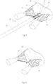
- the valve leaflet connecting device 10 can be configured to the condition shown in Figure 1 to: pull the mitral valve leaflets 24 towards each other (i.e. towards a closed condition); and connect / clip the free ends of the mitral valve leaflets 24 together.
- the catheter 11 comprises a flexible tube sized and shaped to facilitate passage through a patient's vasculature or anatomy.
- the catheter defines a longitudinal axis. Controls (not shown) are disposed at a first axial end of the catheter 11, whereas the base 12, followers 14 (with arms 16), positioner 20 and fastener 22 extend from a second axial end of the catheter 11.
- the base 12 is secured to the second axial end of the catheter 11.
- the base 12 could be made integrally with the second axial end of the catheter 11.
- the base 12 defines a common longitudinal axis (shown as A-A on Figure 1 ) with the catheter 11.
- Each follower 14 comprises a resilient, elongate member.
- Figure 1 shows each follower 14 as a bifurcated member, bifurcating / diverging from the base 12 towards the free end of the follower 14.
- the followers 14 may be movable axially relative to the base 12 and catheter 11.
- the followers 14 are biased to diverge from each other towards the free ends of the followers 14.
- each follower 14 is substantially S-shaped.
- each follower 14 is curved and defines a single inflection point, substantially mid-way along its length. More particularly, each of the first and second followers 14a and 14b defines:
- the followers 14 are made of nitinol. Deformation of the followers 14 could be regulated by variation in cross-sectional geometry (e.g. circular, oval, rectangular) along the length of each follower 14. In addition, living hinges could be incorporated into the followers 14 to facilitate hinged deformation at desired points along the followers 14.
- each arm 16 extends from each follower 14.
- each arm 16 is connected to, and extends from a point on its corresponding follower 14 closer to the free end of the follower than to the base 12 (i.e. within a region from the free end of the follower 14 to a point halfway towards the base 12). More preferably, each arm 16 is connected to the corresponding follower 14 within the region from the free end of the follower 14 to a point a third of the length along the follower 14 (i.e. the end one-third of the follower 14).
- the arms 16 are located at the point of inflection along the followers 14 (i.e. at the junction of the diverging and converging zones of the followers 14).
- the diverging zones on the first and second followers 14a and 14b extend from the base 12 to the first and second arms 16a and 16b, respectively; and (ii) the converging zones on the first and second followers 14a and 14b extend from the first and second arms 16a and 16b, respectively to the free ends of the first and second followers 14a and 14b.
- each arm 16 could be hingedly connected to its corresponding follower 14 to enable the arm 16 to pivot towards its corresponding follower 14, reducing the angle ( ⁇ ) there between.
- each arm 16 could be movable along its corresponding follower 14 using its corresponding arm actuator 25, i.e. towards the free end of the follower 14.
- arms 16a and 16b could be movable along their corresponding followers 14a and 14b using their corresponding arm actuators 25a and 25b independently of one another, i.e. arms 16a and 16b could be movable on their corresponding followers 14a and 14b to different positions along their respective followers 16a and 16b.
- valve leaflet connecting device 10 could further include clamping means (not shown) for moving the first and second arms 16a and 16b from: (i) a receiving condition, in which free ends of the first and second arms 16a and 16b are spaced from the first and second followers 14a and 14b, respectively, for receiving valve leaflets 24 there between; and (ii) a clamped condition, in which the first and second arms 16a and 16b are biased towards the first and second followers 14a and 14b, respectively, for clamping valve leaflets 24 there between.
- clamping means (not shown) for moving the first and second arms 16a and 16b from: (i) a receiving condition, in which free ends of the first and second arms 16a and 16b are spaced from the first and second followers 14a and 14b, respectively, for receiving valve leaflets 24 there between; and (ii) a clamped condition, in which the first and second arms 16a and 16b are biased towards the first and second followers 14a and 14b, respectively, for clamping valve leaflets 24 there between.
- the clamping means and movement of the arms 16 along the followers 14 could be controlled by the controller. It will be appreciated that, if the first and second arms 16a and 16b are hingedly connected to the first and second followers 14a and 14b, respectively, movement of the arms 16 to the clamping condition by the clamping means does not cause the followers 14 to move towards each other.
- Figures 1 to 6 show:
- the first and second followers 14a and 14b are resiliently deformable between:
- spacing in relation to the first and second virtual lines B-B and C-C refers to spacing along a line that extends orthogonally between the first and second virtual lines A-A and B-B.
- the deforming means 18 comprises a tubular collar or sheath located over the second axial end of the catheter 11 / the base 12.
- the deforming means 18 is axially movable relative to the catheter 11 / the base 12 between: (i) a retracted condition, in which the deforming means is wholly located over the base 12 and/or the catheter 11; and (ii) an extended condition, in which the deforming means 18 protrudes at least 15mm axially beyond the axial end of the base 12 distal the catheter 11.
- the deforming means 18 could be moved along the followers 14 to abut the arms 16.
- the deforming means 18 bears against and deforms the followers 14 from the open condition to the closed condition.
- the followers 14 are preferably aligned substantially parallel relative to each other.
- valve leaflet connecting device 10 includes a clamping means
- the clamping means is operable independently or the deforming means 18.
- the positioner 20 is a flexible rod that extends from the centre of the base 12 and that is movable relative to the base 12 along a path that represents an extension of the longitudinal axis of the base 12 / catheter 11.
- the positioner 20 is movable between: (i) a stowed condition, in which the positioner 20 does not protrude more than 5mm axially beyond the axial end of the base 12 distal the catheter 11; and (ii) a locating condition, in which the positioner 20 protrudes at least 15mm axially from the axial end of the base 12 distal the catheter 11.
- the first follower 14a with first arm 16a on the one hand and the second follower 14b with second arm 16b on the other hand are substantially mirrored along a path that represents an extension of the longitudinal axis of the base 12 / catheter 11. Accordingly, the positioner 20 moves along the centre-line between the first follower 14a and the second follower 14b.
- the fastener 22 is disposed on, and releasable secured to the free axial end of the positioner 20.
- the fastener 22 is shown in the form of a clip with pivotally connected first and second fastener 22 jaws that extend from their pivotal connection away from the base 12.
- the fastener 22 jaws are movable between: (i) a splayed condition in which valve leaflets 24 may be received between the first and second fastener 22 jaws; and (ii) a securing condition in which the first and second fastener 22 jaws secure the valve leaflets 24 there between.
- the fastener 22 may be moved to the securing condition by pushing a fastener sheath over the fastener 22 jaws.
- valve leaflet connecting device 10 When the valve leaflet connecting device 10 is in the crimped condition, the followers 14 (with arms 16) and the positioner 20 (with fastener 22) may be fully retracted within the base 12 / lumen defined by the catheter 11, to facilitate movement of the valve leaflet connecting device 10 through a patient's vasculature or anatomy.
- the valve leaflet connecting device 10 further includes hingedly connected stabilising jaws 26 disposed between the first and second followers 14a and 14b.
- the ends of the stabilising jaws 26 distal the hinge connecting the stabilising jaws 26 are connected to the first and second followers 14a and 14b, and the hinged connection of the stabilising jaws 26 are:
- resisting means 28 may vary resistance to displacement of the hinged connection of the stabilising jaws 26 relative to the base 12, thereby to vary stiffness of the first and second followers 14a and 14b. Varying the stiffness of the followers 14 is useful to ensure that the followers 14 remain engaged with the valve leaflets 24 during opening and closing of the valve leaflets 24.
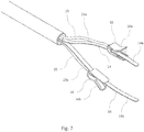
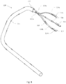
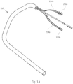
- valve leaflet connecting device 110 A second embodiment of the valve leaflet connecting device 110 is shown in Figures 8 to 12 .
- the second embodiment of the valve leaflet connecting device 110 is similar to the preferred embodiment of the valve leaflet connecting device 10, in that the valve leaflet connecting device 110 includes a similar catheter 111, base 112, controller, positioner 120 and deforming means 118.
- the valve leaflet connecting device 110 includes a similar catheter 111, base 112, controller, positioner 120 and deforming means 118.
- the valve leaflet connecting device 110 includes a similar catheter 111, base 112, controller, positioner 120 and deforming means 118.
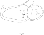
- the followers are not bifurcated and the fastener 122 according to this second embodiment is aligned with the first and second arms 116a and 116b, such that when the follower arms 114 are moved to the closed condition (as shown in Figure 10 ): (i) the first and second arms 116a and 116b may be received between the fastener 122 jaws when the fastener 122 jaws are in the splayed condition; and (ii) subsequent movement of the fastener 122 jaws towards the securing condition causes the first and second arms 116a and 116b to clamp towards the second portions 115 of the first and second followers 114a and 114b, respectively, to capture a valve leaflet 24 between an arm 116 and a second portion 115 of a corresponding follower 114.
- FIG. 11 This is illustrated in Figure 11 .
- the second portions 115 of the followers 114 are disconnected from the first portions of the followers 113 to permit the valve leaflet connecting device 110 (excluding the second portion 115 of the followers 114, the arms 116 and the fastener 122) to be removed from the patient's vasculature or anatomy.
- the first and second arms 216a and 216b are resilient and are axially retractable within, and extendable from the first and second followers 214a and 214b, respectively.
- Such an arrangement is an alternative to the second embodiment of the valve connecting device 110, which requires the second portions 115 of the followers 114 to be dis-connectable from the first portions 113 of the followers 114.
Landscapes
- Health & Medical Sciences (AREA)
- Life Sciences & Earth Sciences (AREA)
- Surgery (AREA)
- Cardiology (AREA)
- General Health & Medical Sciences (AREA)
- Public Health (AREA)
- Heart & Thoracic Surgery (AREA)
- Biomedical Technology (AREA)
- Engineering & Computer Science (AREA)
- Animal Behavior & Ethology (AREA)
- Veterinary Medicine (AREA)
- Nuclear Medicine, Radiotherapy & Molecular Imaging (AREA)
- Medical Informatics (AREA)
- Molecular Biology (AREA)
- Vascular Medicine (AREA)
- Transplantation (AREA)
- Oral & Maxillofacial Surgery (AREA)
- Reproductive Health (AREA)
- Prostheses (AREA)
- Surgical Instruments (AREA)
- Infusion, Injection, And Reservoir Apparatuses (AREA)
- Quick-Acting Or Multi-Walled Pipe Joints (AREA)
Claims (21)
- Dispositif de connexion de feuillet de valve (10) comprenant :une base (12) qui définit un axe longitudinal (A-A) ;des premier et second suiveurs (14) s'étendant depuis la base ;un premier bras (16a) sur le premier suiveur (14a), lequel premier bras s'étend depuis le premier suiveur dans une direction s'éloignant du second suiveur (14b) et s'éloignant de la base pour définir un angle aigu entre le premier suiveur et le premier bras pour capturer un premier feuillet (24) entre eux ;un second bras (16b) sur le second suiveur, lequel second bras s'étend depuis le second suiveur dans une direction s'éloignant du premier suiveur et s'éloignant de la base pour définir un angle aigu entre le second suiveur et le second bras pour capturer un second feuillet entre eux ;caractérisé en ce que les premier et second suiveurs sont déformables élastiquement entre :
une condition ouverte, dans laquelle :une première ligne virtuelle (B-B) qui : coupe le point à partir duquel le premier bras s'étend depuis le premier suiveur ; et est parallèle à l'axe longitudinal de la base ; etune seconde ligne virtuelle (C-C) qui : coupe le point à partir duquel le second bras s'étend depuis le second suiveur ; et est parallèle à l'axe longitudinal de la base,sont espacées de plus de 15 mm ; etune condition fermée, dans laquelle les première et seconde lignes virtuelles sont espacées de moins de 5 mm ; etdes moyens de déformation (18) pour déformer les suiveurs vers la condition fermée, de telle sorte qu'en utilisation :(i) les premier et second suiveurs puissent être : passés axialement à travers une valve, entre des premier et second feuillets de valve ; et déformés élastiquement par ouverture et fermeture des feuillets de valve ;(ii) le premier bras puisse capturer le premier feuillet entre le premier bras et le premier suiveur, et le second bras puisse capturer le second feuillet entre le second bras et le second suiveur, les premier et second suiveurs étant disposés entre les premier et second feuillets ; et(iii) les moyens de déformation puissent déformer les premier et second suiveurs vers la condition fermée, déplaçant ainsi les premier et second feuillets l'un vers l'autre. - Dispositif de connexion de feuillet de valve selon la revendication 1, comprenant en outre :un positionneur (20) s'étendant depuis la base, entre les premier et second suiveurs ; etune attache (22) fixée de manière amovible au positionneur, laquelle attache comprend des première et seconde mâchoires d'attache qui :s'éloignent de la base ; etsont mobiles entre : (i) une condition évasée dans laquelle des feuillets peuvent être reçus entre les première et seconde mâchoires d'attache ; et (ii) une condition de fixation dans laquelle les première et seconde mâchoires d'attache fixent les feuillets entre eux, de telle sorte que, lors de l'utilisation, lorsque les premier et second feuillets sont déplacés l'un vers l'autre :(i) l'attache puisse recevoir les premier et second feuillets entre les mâchoires d'attache lorsque les mâchoires d'attache sont dans la condition évasée ; et(ii) le déplacement des mâchoires d'attache vers la condition de fixation fixe les premier et second feuillets l'un à l'autre.
- Dispositif de connexion de feuillet de valve (110) comprenant :une base (112) qui définit un axe longitudinal (A-A) ;des premier et second suiveurs (114) s'étendant depuis la base ;un premier bras (116a) sur le premier suiveur (114a), lequel premier bras s'étend depuis le premier suiveur dans une direction s'éloignant du second suiveur (114b) et vers la base pour définir un angle aigu entre le premier suiveur et le premier bras pour capturer un premier feuillet (24) entre eux ;un second bras (116b) sur le second suiveur, lequel second bras s'étend depuis le second suiveur dans une direction s'éloignant du premier suiveur et vers la base pour définir un angle aigu entre le second suiveur et le second bras pour capturer un second feuillet entre eux ;caractérisé en ce que les premier et second suiveurs sont déformables élastiquement entre :
une condition ouverte, dans laquelle :une première ligne virtuelle qui : coupe le point à partir duquel le premier bras s'étend depuis le premier suiveur ; et est parallèle à l'axe longitudinal de la base ; etune deuxième ligne virtuelle qui : coupe le point à partir duquel le second bras s'étend depuis le second suiveur ; et est parallèle à l'axe longitudinal de la base,sont espacées de plus de 15 mm ; etune condition fermée, dans laquelle les première et seconde lignes virtuelles sont espacées de moins de 5 mm ; etdes moyens de déformation (118) pour déformer les suiveurs vers la condition fermée, de telle sorte qu'en utilisation :(i) les premier et second suiveurs puissent être : passés axialement à travers une valve, entre des premier et second feuillets de valve ; et déformés élastiquement par ouverture et fermeture des feuillets de valve ;(ii) le premier bras puisse capturer le premier feuillet entre le premier bras et le premier suiveur, et le second bras puisse capturer le second feuillet entre le second bras et le second suiveur, les premier et second suiveurs étant disposés entre les premier et second feuillets ; et(iii) les moyens de déformation puissent déformer les premier et second suiveurs vers la condition fermée, déplaçant ainsi les premier et second feuillets l'un vers l'autre. - Dispositif de connexion de feuillet de valve selon la revendication 3, comprenant en outre :un positionneur (120) s'étendant depuis la base, entre les premier et second suiveurs ; etune attache (122) fixée de manière amovible au positionneur, laquelle attache comprend des première et seconde mâchoires d'attache qui :s'étendent vers la base ; etsont mobiles entre :(i) une condition évasée dans laquelle des feuillets peuvent être reçus entre les première et seconde mâchoires d'attache ; et(ii) une condition de fixation dans laquelle les première et seconde mâchoires d'attache fixent les feuillets entre eux, de telle sorte que, lors de l'utilisation, lorsque les premier et second feuillets sont déplacés l'un vers l'autre :(i) l'attache puisse recevoir les premier et second feuillets entre les mâchoires d'attache lorsque les mâchoires d'attache sont dans la condition évasée ; et(ii) le déplacement des mâchoires d'attache vers la condition de fixation fixe les premier et second feuillets l'un à l'autre.
- Dispositif de connexion de feuillet de valve (10, 110) selon la revendication 2, dans lequel :le premier bras (16a, 116a) s'étend depuis le premier suiveur (14a, 114a) sur au moins 3 mm ; etle second bras (16b, 116b) s'étend depuis le second suiveur (14b, 114b) sur au moins 3 mm.
- Dispositif de connexion de feuillet de valve selon la revendication 5, comprenant en outre un cathéter (11, 111), et dans lequel la base (12, 112) est disposée au niveau de, ou définie par une première extrémité axiale du cathéter.
- Dispositif de connexion de feuillet de valve selon la revendication 6, dans lequel les premier et second suiveurs et le positionneur : (i) s'étendent à partir d'une lumière s'étendant axialement définie par le cathéter et la base ; et (ii) sont mobiles axialement le long de la lumière s'étendant axialement définie par le cathéter.
- Dispositif de connexion de feuillet de valve selon la revendication 7, comprenant en outre des moyens de commande au niveau de ou près d'une seconde extrémité axiale du cathéter pour :commander le mouvement axial relatif du cathéter d'une part et les premier et second suiveurs d'autre part ;commander le mouvement axial relatif du cathéter et du positionneur, pour ainsi faire varier la position de l'attache par rapport aux premier et second bras ; etcommander le mouvement des mâchoires d'attache depuis la condition évasée vers la condition de fixation.
- Dispositif de connexion de feuillet de valve selon la revendication 8, dans lequel le premier bras est connecté de manière articulée au premier suiveur et le second bras est connecté de manière articulée au second suiveur.
- Dispositif de connexion de feuillet de valve selon la revendication 9, dans lequel les premier et second bras sont mobiles le long des premier et second suiveurs, respectivement.
- Dispositif de connexion de feuillet de valve selon la revendication 10, dans lequel le premier bras est mobile le long du premier suiveur indépendamment du mouvement du second bras le long du second suiveur.
- Dispositif de connexion de feuillet de valve selon la revendication 11, comprenant en outre des moyens de serrage pour déplacer les premier et second bras depuis : (i) une condition de réception, dans laquelle les extrémités libres des premier et second bras sont espacées des premier et second suiveurs, respectivement, pour recevoir des feuillets entre eux ; et (ii) une condition serrée, dans laquelle les premier et second bras sont rappelés vers les premier et second suiveurs, respectivement, pour serrer les feuillets entre eux.
- Dispositif de connexion de feuillet de valve selon la revendication 12, dans lequel le moyen de serrage peut fonctionner indépendamment du moyen de déformation.
- Dispositif de connexion de feuillet de valve selon la revendication 13, dans lequel chacun des premier et second suiveurs définissent : (i) une zone divergente à proximité de la base, le long de laquelle zone divergente les premier et second suiveurs divergent l'un de l'autre lorsqu'ils s'étendent depuis la base ; et (ii) une zone convergente, le long de laquelle les premier et second suiveurs convergent l'un vers l'autre lorsqu'ils s'étendent depuis l'extrémité de la zone divergente distale de la base.
- Dispositif de connexion de feuillet de valve selon la revendication 14, dans lequel : (i) les zones divergentes sur les premier et second suiveurs s'étendent depuis la base vers les premier et second bras, respectivement ; et (ii) les zones convergentes sur les premier et second suiveurs s'étendent depuis les premier et second bras, respectivement vers les extrémités libres des premier et second suiveurs.
- Dispositif de connexion de feuillet de valve selon la revendication 4, dans lequel :chacun des premier et second suiveurs (114a et 114b) comprennent : (i) une première partie (113) qui s'étend depuis la base (112) et se termine avant les points au niveau desquels les premier et second bras (116a et 116b) s'étendent depuis les premier et second suiveurs, respectivement ; et (ii) une seconde partie (115) qui s'étend depuis l'extrémité de la première partie vers les extrémités libres des premier et second suiveurs, respectivement ; eten ce qui concerne chacun des premier et second suiveurs, la première partie est fixée de manière amovible à la seconde partie.
- Dispositif de connexion de feuillet de valve selon la revendication 16, dans lequel l'attache est alignée avec les premier et second bras, de telle sorte que : (i) les premier et second bras puissent être reçus entre les mâchoires d'attache lorsque les mâchoires d'attache sont dans la condition évasée ; et (ii) un mouvement ultérieur des mâchoires d'attache vers la condition de fixation amène les premier et second bras à se serrer contre les premier et second suiveurs, respectivement.
- Dispositif de connexion de feuillet de valve selon la revendication 4, dans lequel les premier et second bras sont élastiques et sont axialement rétractables à l'intérieur, et extensibles depuis les premier et second suiveurs, respectivement.
- Dispositif de connexion de feuillet de valve selon la revendication 2, dans lequel chacun des premier et second suiveurs sont bifurqués vers leur extrémité libre, pour recevoir l'attache entre les bifurcations.
- Dispositif de connexion de feuillet de valve selon la revendication 5, comprenant en outre des mâchoires de stabilisation connectées de manière articulée (26) disposées entre les premier et second suiveurs, les extrémités des mâchoires de stabilisation distales de la charnière étant connectées aux premier et second suiveurs et la connexion articulée des mâchoires de stabilisation étant :située entre le premier et le second suiveurs ; etespacée de la base, de sorte que la déformation des premier et second suiveurs entre les conditions ouverte et fermée provoque le déplacement de la connexion articulée des mâchoires de stabilisation par rapport à la base.
- Dispositif de connexion de feuillet de valve selon la revendication 20, comprenant en outre des moyens de résistance (28) pour résister au déplacement de la connexion articulée des mâchoires de stabilisation par rapport à la base, pour ainsi faire varier la rigidité des premier et second suiveurs.
Applications Claiming Priority (2)
| Application Number | Priority Date | Filing Date | Title |
|---|---|---|---|
| GB1709509.2A GB2563420B (en) | 2017-06-15 | 2017-06-15 | Valve leaflet connecting device |
| PCT/ZA2018/050034 WO2018232425A1 (fr) | 2017-06-15 | 2018-06-11 | Dispositif de connexion de feuillet de valve |
Publications (2)
| Publication Number | Publication Date |
|---|---|
| EP3638128A1 EP3638128A1 (fr) | 2020-04-22 |
| EP3638128B1 true EP3638128B1 (fr) | 2021-03-03 |
Family
ID=59462532
Family Applications (1)
| Application Number | Title | Priority Date | Filing Date |
|---|---|---|---|
| EP18742891.7A Active EP3638128B1 (fr) | 2017-06-15 | 2018-06-11 | Dispositif de connexion de feuillet de valve |
Country Status (8)
| Country | Link |
|---|---|
| US (1) | US10925736B2 (fr) |
| EP (1) | EP3638128B1 (fr) |
| CN (1) | CN110891494B (fr) |
| BR (1) | BR112019026318B1 (fr) |
| GB (1) | GB2563420B (fr) |
| RU (1) | RU2755393C2 (fr) |
| WO (1) | WO2018232425A1 (fr) |
| ZA (1) | ZA202000149B (fr) |
Families Citing this family (1)
| Publication number | Priority date | Publication date | Assignee | Title |
|---|---|---|---|---|
| JP7728963B2 (ja) * | 2021-09-01 | 2025-08-25 | ボストン サイエンティフィック サイムド,インコーポレイテッド | 心臓弁の弁尖をクランプするためのデバイス、システム、および方法 |
Family Cites Families (7)
| Publication number | Priority date | Publication date | Assignee | Title |
|---|---|---|---|---|
| EP2078498B1 (fr) | 1999-04-09 | 2010-12-22 | Evalve, Inc. | Appareil pour la réparation de valves cardiaques |
| US8052592B2 (en) * | 2005-09-27 | 2011-11-08 | Evalve, Inc. | Methods and devices for tissue grasping and assessment |
| DE102007005900A1 (de) * | 2007-02-01 | 2008-08-07 | Endosmart Gesellschaft für innovative Medizintechnik mbH | Instrument zum operativen Entfernen einer defekten Herzklappe |
| WO2010041125A1 (fr) * | 2008-10-09 | 2010-04-15 | Peter Paul Zilla | Dispositif de déploiement d'une endoprothèse |
| KR20140029427A (ko) * | 2011-04-04 | 2014-03-10 | 더 메디컬 리서치, 인프라스트럭쳐, 앤드 헬스 서비시즈 펀드 오브 더 텔 아비브 메디컬 센터 | 심장 판막 치료 장치 및 방법 |
| US10524792B2 (en) * | 2014-12-04 | 2020-01-07 | Edwards Lifesciences Corporation | Percutaneous clip for repairing a heart valve |
| WO2016110760A1 (fr) * | 2015-01-05 | 2016-07-14 | Strait Access Technologies Holdings (Pty) Ltd | Dispositif de capture de feuillet de valvule cardiaque |
-
2017
- 2017-06-15 GB GB1709509.2A patent/GB2563420B/en active Active
-
2018
- 2018-06-10 US US16/622,500 patent/US10925736B2/en active Active
- 2018-06-11 EP EP18742891.7A patent/EP3638128B1/fr active Active
- 2018-06-11 RU RU2019143377A patent/RU2755393C2/ru active
- 2018-06-11 WO PCT/ZA2018/050034 patent/WO2018232425A1/fr not_active Ceased
- 2018-06-11 BR BR112019026318-7A patent/BR112019026318B1/pt active IP Right Grant
- 2018-06-11 CN CN201880047388.7A patent/CN110891494B/zh active Active
-
2020
- 2020-01-09 ZA ZA2020/00149A patent/ZA202000149B/en unknown
Non-Patent Citations (1)
| Title |
|---|
| None * |
Also Published As
| Publication number | Publication date |
|---|---|
| RU2755393C2 (ru) | 2021-09-15 |
| BR112019026318B1 (pt) | 2023-11-28 |
| US20200375741A1 (en) | 2020-12-03 |
| BR112019026318A2 (pt) | 2020-06-23 |
| CN110891494A (zh) | 2020-03-17 |
| GB201709509D0 (en) | 2017-08-02 |
| WO2018232425A1 (fr) | 2018-12-20 |
| RU2019143377A3 (fr) | 2021-08-25 |
| US10925736B2 (en) | 2021-02-23 |
| GB2563420A (en) | 2018-12-19 |
| ZA202000149B (en) | 2021-01-27 |
| EP3638128A1 (fr) | 2020-04-22 |
| GB2563420B (en) | 2019-09-18 |
| RU2019143377A (ru) | 2021-06-24 |
| CN110891494B (zh) | 2022-12-13 |
Similar Documents
| Publication | Publication Date | Title |
|---|---|---|
| US9999425B2 (en) | Mitral valve leaflet clip | |
| JP7068161B2 (ja) | 心臓弁尖を固定するためのデバイス | |
| US8974475B2 (en) | Methods and devices for cardiac valve repair or replacement | |
| EP3547962B1 (fr) | Fil de serrage et pilier pour réparation de valve tricuspide | |
| CN107427305B (zh) | 心脏瓣膜小叶捕获装置 | |
| US9254141B2 (en) | Apparatus and method for heart valve repair | |
| US10058348B2 (en) | Apparatus and method for heart valve repair | |
| CN110996851B (zh) | 心脏瓣膜植入物和心脏瓣膜植入物系统 | |
| EP2806805B1 (fr) | Appareil de réparation de valvule cardiaque | |
| EP2670313B1 (fr) | Appareil de réparation de valvules cardiaques | |
| CN212662029U (zh) | 夹持装置及包含其的瓣膜修复器械 | |
| EP3193782B1 (fr) | Système d'annuloplastie | |
| JP2022511805A5 (fr) | ||
| CN107920813A (zh) | 组织夹持装置及相关方法 | |
| EP3410959B1 (fr) | Pince large pour hémostase | |
| AU2005299615B2 (en) | Fixation devices for variation in engagement of tissue | |
| CN112206075A (zh) | 一种经导管植入式心脏瓣膜夹合器 | |
| CN113288516A (zh) | 一种锚定夹及使用其的瓣膜闭合器械 | |
| US10925736B2 (en) | Valve leaflet connecting device | |
| EP4389071A1 (fr) | Système de serrage de tissu | |
| CN113440309A (zh) | 用于紧固推杆的可释放组件 | |
| CN117281663A (zh) | 瓣膜夹合装置及瓣膜修复系统 | |
| CN113440307A (zh) | 夹持装置及包含其的瓣膜修复器械 | |
| CN117045291A (zh) | 瓣环环缩器械 | |
| JP2025538214A (ja) | 調整可能な固定デバイス |
Legal Events
| Date | Code | Title | Description |
|---|---|---|---|
| STAA | Information on the status of an ep patent application or granted ep patent |
Free format text: STATUS: UNKNOWN |
|
| STAA | Information on the status of an ep patent application or granted ep patent |
Free format text: STATUS: THE INTERNATIONAL PUBLICATION HAS BEEN MADE |
|
| PUAI | Public reference made under article 153(3) epc to a published international application that has entered the european phase |
Free format text: ORIGINAL CODE: 0009012 |
|
| STAA | Information on the status of an ep patent application or granted ep patent |
Free format text: STATUS: REQUEST FOR EXAMINATION WAS MADE |
|
| 17P | Request for examination filed |
Effective date: 20200110 |
|
| AK | Designated contracting states |
Kind code of ref document: A1 Designated state(s): AL AT BE BG CH CY CZ DE DK EE ES FI FR GB GR HR HU IE IS IT LI LT LU LV MC MK MT NL NO PL PT RO RS SE SI SK SM TR |
|
| AX | Request for extension of the european patent |
Extension state: BA ME |
|
| DAV | Request for validation of the european patent (deleted) | ||
| DAX | Request for extension of the european patent (deleted) | ||
| GRAP | Despatch of communication of intention to grant a patent |
Free format text: ORIGINAL CODE: EPIDOSNIGR1 |
|
| STAA | Information on the status of an ep patent application or granted ep patent |
Free format text: STATUS: GRANT OF PATENT IS INTENDED |
|
| RIC1 | Information provided on ipc code assigned before grant |
Ipc: A61B 17/122 20060101ALN20201026BHEP Ipc: A61B 17/08 20060101ALN20201026BHEP Ipc: A61B 17/128 20060101ALI20201026BHEP Ipc: A61B 17/00 20060101AFI20201026BHEP |
|
| INTG | Intention to grant announced |
Effective date: 20201113 |
|
| RBV | Designated contracting states (corrected) |
Designated state(s): AL AT BE BG CH CY CZ DE DK EE ES FI FR GR HR HU IE IS IT LI LT LU LV MC MK MT NL NO PL PT RO RS SE SI SK SM TR |
|
| GRAS | Grant fee paid |
Free format text: ORIGINAL CODE: EPIDOSNIGR3 |
|
| GRAA | (expected) grant |
Free format text: ORIGINAL CODE: 0009210 |
|
| STAA | Information on the status of an ep patent application or granted ep patent |
Free format text: STATUS: THE PATENT HAS BEEN GRANTED |
|
| AK | Designated contracting states |
Kind code of ref document: B1 Designated state(s): AL AT BE BG CH CY CZ DE DK EE ES FI FR GR HR HU IE IS IT LI LT LU LV MC MK MT NL NO PL PT RO RS SE SI SK SM TR |
|
| REG | Reference to a national code |
Ref country code: CH Ref legal event code: EP Ref country code: CH Ref legal event code: NV Representative=s name: NOVAGRAAF INTERNATIONAL SA, CH Ref country code: AT Ref legal event code: REF Ref document number: 1366342 Country of ref document: AT Kind code of ref document: T Effective date: 20210315 |
|
| REG | Reference to a national code |
Ref country code: DE Ref legal event code: R096 Ref document number: 602018013480 Country of ref document: DE |
|
| REG | Reference to a national code |
Ref country code: IE Ref legal event code: FG4D |
|
| REG | Reference to a national code |
Ref country code: NL Ref legal event code: FP |
|
| REG | Reference to a national code |
Ref country code: LT Ref legal event code: MG9D |
|
| PG25 | Lapsed in a contracting state [announced via postgrant information from national office to epo] |
Ref country code: GR Free format text: LAPSE BECAUSE OF FAILURE TO SUBMIT A TRANSLATION OF THE DESCRIPTION OR TO PAY THE FEE WITHIN THE PRESCRIBED TIME-LIMIT Effective date: 20210604 Ref country code: FI Free format text: LAPSE BECAUSE OF FAILURE TO SUBMIT A TRANSLATION OF THE DESCRIPTION OR TO PAY THE FEE WITHIN THE PRESCRIBED TIME-LIMIT Effective date: 20210303 Ref country code: HR Free format text: LAPSE BECAUSE OF FAILURE TO SUBMIT A TRANSLATION OF THE DESCRIPTION OR TO PAY THE FEE WITHIN THE PRESCRIBED TIME-LIMIT Effective date: 20210303 Ref country code: BG Free format text: LAPSE BECAUSE OF FAILURE TO SUBMIT A TRANSLATION OF THE DESCRIPTION OR TO PAY THE FEE WITHIN THE PRESCRIBED TIME-LIMIT Effective date: 20210603 Ref country code: LT Free format text: LAPSE BECAUSE OF FAILURE TO SUBMIT A TRANSLATION OF THE DESCRIPTION OR TO PAY THE FEE WITHIN THE PRESCRIBED TIME-LIMIT Effective date: 20210303 Ref country code: NO Free format text: LAPSE BECAUSE OF FAILURE TO SUBMIT A TRANSLATION OF THE DESCRIPTION OR TO PAY THE FEE WITHIN THE PRESCRIBED TIME-LIMIT Effective date: 20210603 |
|
| REG | Reference to a national code |
Ref country code: AT Ref legal event code: MK05 Ref document number: 1366342 Country of ref document: AT Kind code of ref document: T Effective date: 20210303 |
|
| PG25 | Lapsed in a contracting state [announced via postgrant information from national office to epo] |
Ref country code: SE Free format text: LAPSE BECAUSE OF FAILURE TO SUBMIT A TRANSLATION OF THE DESCRIPTION OR TO PAY THE FEE WITHIN THE PRESCRIBED TIME-LIMIT Effective date: 20210303 Ref country code: PL Free format text: LAPSE BECAUSE OF FAILURE TO SUBMIT A TRANSLATION OF THE DESCRIPTION OR TO PAY THE FEE WITHIN THE PRESCRIBED TIME-LIMIT Effective date: 20210303 Ref country code: LV Free format text: LAPSE BECAUSE OF FAILURE TO SUBMIT A TRANSLATION OF THE DESCRIPTION OR TO PAY THE FEE WITHIN THE PRESCRIBED TIME-LIMIT Effective date: 20210303 Ref country code: RS Free format text: LAPSE BECAUSE OF FAILURE TO SUBMIT A TRANSLATION OF THE DESCRIPTION OR TO PAY THE FEE WITHIN THE PRESCRIBED TIME-LIMIT Effective date: 20210303 |
|
| PG25 | Lapsed in a contracting state [announced via postgrant information from national office to epo] |
Ref country code: CZ Free format text: LAPSE BECAUSE OF FAILURE TO SUBMIT A TRANSLATION OF THE DESCRIPTION OR TO PAY THE FEE WITHIN THE PRESCRIBED TIME-LIMIT Effective date: 20210303 Ref country code: EE Free format text: LAPSE BECAUSE OF FAILURE TO SUBMIT A TRANSLATION OF THE DESCRIPTION OR TO PAY THE FEE WITHIN THE PRESCRIBED TIME-LIMIT Effective date: 20210303 Ref country code: SM Free format text: LAPSE BECAUSE OF FAILURE TO SUBMIT A TRANSLATION OF THE DESCRIPTION OR TO PAY THE FEE WITHIN THE PRESCRIBED TIME-LIMIT Effective date: 20210303 Ref country code: AT Free format text: LAPSE BECAUSE OF FAILURE TO SUBMIT A TRANSLATION OF THE DESCRIPTION OR TO PAY THE FEE WITHIN THE PRESCRIBED TIME-LIMIT Effective date: 20210303 |
|
| PG25 | Lapsed in a contracting state [announced via postgrant information from national office to epo] |
Ref country code: SK Free format text: LAPSE BECAUSE OF FAILURE TO SUBMIT A TRANSLATION OF THE DESCRIPTION OR TO PAY THE FEE WITHIN THE PRESCRIBED TIME-LIMIT Effective date: 20210303 Ref country code: PT Free format text: LAPSE BECAUSE OF FAILURE TO SUBMIT A TRANSLATION OF THE DESCRIPTION OR TO PAY THE FEE WITHIN THE PRESCRIBED TIME-LIMIT Effective date: 20210705 Ref country code: RO Free format text: LAPSE BECAUSE OF FAILURE TO SUBMIT A TRANSLATION OF THE DESCRIPTION OR TO PAY THE FEE WITHIN THE PRESCRIBED TIME-LIMIT Effective date: 20210303 Ref country code: IS Free format text: LAPSE BECAUSE OF FAILURE TO SUBMIT A TRANSLATION OF THE DESCRIPTION OR TO PAY THE FEE WITHIN THE PRESCRIBED TIME-LIMIT Effective date: 20210703 |
|
| REG | Reference to a national code |
Ref country code: DE Ref legal event code: R097 Ref document number: 602018013480 Country of ref document: DE |
|
| PLBE | No opposition filed within time limit |
Free format text: ORIGINAL CODE: 0009261 |
|
| STAA | Information on the status of an ep patent application or granted ep patent |
Free format text: STATUS: NO OPPOSITION FILED WITHIN TIME LIMIT |
|
| PG25 | Lapsed in a contracting state [announced via postgrant information from national office to epo] |
Ref country code: MC Free format text: LAPSE BECAUSE OF FAILURE TO SUBMIT A TRANSLATION OF THE DESCRIPTION OR TO PAY THE FEE WITHIN THE PRESCRIBED TIME-LIMIT Effective date: 20210303 Ref country code: AL Free format text: LAPSE BECAUSE OF FAILURE TO SUBMIT A TRANSLATION OF THE DESCRIPTION OR TO PAY THE FEE WITHIN THE PRESCRIBED TIME-LIMIT Effective date: 20210303 Ref country code: DK Free format text: LAPSE BECAUSE OF FAILURE TO SUBMIT A TRANSLATION OF THE DESCRIPTION OR TO PAY THE FEE WITHIN THE PRESCRIBED TIME-LIMIT Effective date: 20210303 Ref country code: ES Free format text: LAPSE BECAUSE OF FAILURE TO SUBMIT A TRANSLATION OF THE DESCRIPTION OR TO PAY THE FEE WITHIN THE PRESCRIBED TIME-LIMIT Effective date: 20210303 |
|
| 26N | No opposition filed |
Effective date: 20211206 |
|
| PG25 | Lapsed in a contracting state [announced via postgrant information from national office to epo] |
Ref country code: SI Free format text: LAPSE BECAUSE OF FAILURE TO SUBMIT A TRANSLATION OF THE DESCRIPTION OR TO PAY THE FEE WITHIN THE PRESCRIBED TIME-LIMIT Effective date: 20210303 |
|
| REG | Reference to a national code |
Ref country code: BE Ref legal event code: MM Effective date: 20210630 |
|
| PG25 | Lapsed in a contracting state [announced via postgrant information from national office to epo] |
Ref country code: LU Free format text: LAPSE BECAUSE OF NON-PAYMENT OF DUE FEES Effective date: 20210611 |
|
| PG25 | Lapsed in a contracting state [announced via postgrant information from national office to epo] |
Ref country code: IT Free format text: LAPSE BECAUSE OF FAILURE TO SUBMIT A TRANSLATION OF THE DESCRIPTION OR TO PAY THE FEE WITHIN THE PRESCRIBED TIME-LIMIT Effective date: 20210303 Ref country code: IE Free format text: LAPSE BECAUSE OF NON-PAYMENT OF DUE FEES Effective date: 20210611 |
|
| PG25 | Lapsed in a contracting state [announced via postgrant information from national office to epo] |
Ref country code: IS Free format text: LAPSE BECAUSE OF FAILURE TO SUBMIT A TRANSLATION OF THE DESCRIPTION OR TO PAY THE FEE WITHIN THE PRESCRIBED TIME-LIMIT Effective date: 20210703 |
|
| PG25 | Lapsed in a contracting state [announced via postgrant information from national office to epo] |
Ref country code: BE Free format text: LAPSE BECAUSE OF NON-PAYMENT OF DUE FEES Effective date: 20210630 |
|
| PG25 | Lapsed in a contracting state [announced via postgrant information from national office to epo] |
Ref country code: CY Free format text: LAPSE BECAUSE OF FAILURE TO SUBMIT A TRANSLATION OF THE DESCRIPTION OR TO PAY THE FEE WITHIN THE PRESCRIBED TIME-LIMIT Effective date: 20210303 |
|
| PG25 | Lapsed in a contracting state [announced via postgrant information from national office to epo] |
Ref country code: HU Free format text: LAPSE BECAUSE OF FAILURE TO SUBMIT A TRANSLATION OF THE DESCRIPTION OR TO PAY THE FEE WITHIN THE PRESCRIBED TIME-LIMIT; INVALID AB INITIO Effective date: 20180611 |
|
| PG25 | Lapsed in a contracting state [announced via postgrant information from national office to epo] |
Ref country code: MK Free format text: LAPSE BECAUSE OF FAILURE TO SUBMIT A TRANSLATION OF THE DESCRIPTION OR TO PAY THE FEE WITHIN THE PRESCRIBED TIME-LIMIT Effective date: 20210303 |
|
| PG25 | Lapsed in a contracting state [announced via postgrant information from national office to epo] |
Ref country code: MT Free format text: LAPSE BECAUSE OF FAILURE TO SUBMIT A TRANSLATION OF THE DESCRIPTION OR TO PAY THE FEE WITHIN THE PRESCRIBED TIME-LIMIT Effective date: 20210303 |
|
| PGFP | Annual fee paid to national office [announced via postgrant information from national office to epo] |
Ref country code: DE Payment date: 20250619 Year of fee payment: 8 |
|
| PGFP | Annual fee paid to national office [announced via postgrant information from national office to epo] |
Ref country code: NL Payment date: 20250619 Year of fee payment: 8 |
|
| PGFP | Annual fee paid to national office [announced via postgrant information from national office to epo] |
Ref country code: FR Payment date: 20250617 Year of fee payment: 8 |
|
| PGFP | Annual fee paid to national office [announced via postgrant information from national office to epo] |
Ref country code: CH Payment date: 20250701 Year of fee payment: 8 |
|
| PG25 | Lapsed in a contracting state [announced via postgrant information from national office to epo] |
Ref country code: TR Free format text: LAPSE BECAUSE OF FAILURE TO SUBMIT A TRANSLATION OF THE DESCRIPTION OR TO PAY THE FEE WITHIN THE PRESCRIBED TIME-LIMIT Effective date: 20210303 |