EP3638423B1 - Broyeur oscillant et procédé de broyage d'un produit à broyer - Google Patents
Broyeur oscillant et procédé de broyage d'un produit à broyer Download PDFInfo
- Publication number
- EP3638423B1 EP3638423B1 EP19725934.4A EP19725934A EP3638423B1 EP 3638423 B1 EP3638423 B1 EP 3638423B1 EP 19725934 A EP19725934 A EP 19725934A EP 3638423 B1 EP3638423 B1 EP 3638423B1
- Authority
- EP
- European Patent Office
- Prior art keywords
- gravity
- centre
- pendulum drive
- motor unit
- eccentric shaft
- Prior art date
- Legal status (The legal status is an assumption and is not a legal conclusion. Google has not performed a legal analysis and makes no representation as to the accuracy of the status listed.)
- Active
Links
Images


Classifications
-
- B—PERFORMING OPERATIONS; TRANSPORTING
- B02—CRUSHING, PULVERISING, OR DISINTEGRATING; PREPARATORY TREATMENT OF GRAIN FOR MILLING
- B02C—CRUSHING, PULVERISING, OR DISINTEGRATING IN GENERAL; MILLING GRAIN
- B02C17/00—Disintegrating by tumbling mills, i.e. mills having a container charged with the material to be disintegrated with or without special disintegrating members such as pebbles or balls
- B02C17/14—Mills in which the charge to be ground is turned over by movements of the container other than by rotating, e.g. by swinging, vibrating, tilting
-
- G—PHYSICS
- G01—MEASURING; TESTING
- G01N—INVESTIGATING OR ANALYSING MATERIALS BY DETERMINING THEIR CHEMICAL OR PHYSICAL PROPERTIES
- G01N1/00—Sampling; Preparing specimens for investigation
- G01N1/28—Preparing specimens for investigation including physical details of (bio-)chemical methods covered elsewhere, e.g. G01N33/50, C12Q
- G01N1/286—Preparing specimens for investigation including physical details of (bio-)chemical methods covered elsewhere, e.g. G01N33/50, C12Q involving mechanical work, e.g. chopping, disintegrating, compacting, homogenising
-
- B—PERFORMING OPERATIONS; TRANSPORTING
- B01—PHYSICAL OR CHEMICAL PROCESSES OR APPARATUS IN GENERAL
- B01L—CHEMICAL OR PHYSICAL LABORATORY APPARATUS FOR GENERAL USE
- B01L9/00—Supporting devices; Holding devices
-
- B—PERFORMING OPERATIONS; TRANSPORTING
- B02—CRUSHING, PULVERISING, OR DISINTEGRATING; PREPARATORY TREATMENT OF GRAIN FOR MILLING
- B02C—CRUSHING, PULVERISING, OR DISINTEGRATING IN GENERAL; MILLING GRAIN
- B02C19/00—Other disintegrating devices or methods
- B02C19/0012—Devices for disintegrating materials by collision of these materials against a breaking surface or breaking body and/or by friction between the material particles (also for grain)
- B02C19/005—Devices for disintegrating materials by collision of these materials against a breaking surface or breaking body and/or by friction between the material particles (also for grain) the materials to be pulverised being disintegrated by collision of, or friction between, the material particles
-
- B—PERFORMING OPERATIONS; TRANSPORTING
- B02—CRUSHING, PULVERISING, OR DISINTEGRATING; PREPARATORY TREATMENT OF GRAIN FOR MILLING
- B02C—CRUSHING, PULVERISING, OR DISINTEGRATING IN GENERAL; MILLING GRAIN
- B02C19/00—Other disintegrating devices or methods
- B02C19/16—Mills provided with vibrators
-
- B—PERFORMING OPERATIONS; TRANSPORTING
- B01—PHYSICAL OR CHEMICAL PROCESSES OR APPARATUS IN GENERAL
- B01L—CHEMICAL OR PHYSICAL LABORATORY APPARATUS FOR GENERAL USE
- B01L2300/00—Additional constructional details
- B01L2300/06—Auxiliary integrated devices, integrated components
-
- B—PERFORMING OPERATIONS; TRANSPORTING
- B01—PHYSICAL OR CHEMICAL PROCESSES OR APPARATUS IN GENERAL
- B01L—CHEMICAL OR PHYSICAL LABORATORY APPARATUS FOR GENERAL USE
- B01L2300/00—Additional constructional details
- B01L2300/06—Auxiliary integrated devices, integrated components
- B01L2300/0609—Holders integrated in container to position an object
-
- B—PERFORMING OPERATIONS; TRANSPORTING
- B01—PHYSICAL OR CHEMICAL PROCESSES OR APPARATUS IN GENERAL
- B01L—CHEMICAL OR PHYSICAL LABORATORY APPARATUS FOR GENERAL USE
- B01L2300/00—Additional constructional details
- B01L2300/08—Geometry, shape and general structure
- B01L2300/0809—Geometry, shape and general structure rectangular shaped
-
- G—PHYSICS
- G01—MEASURING; TESTING
- G01N—INVESTIGATING OR ANALYSING MATERIALS BY DETERMINING THEIR CHEMICAL OR PHYSICAL PROPERTIES
- G01N1/00—Sampling; Preparing specimens for investigation
- G01N1/28—Preparing specimens for investigation including physical details of (bio-)chemical methods covered elsewhere, e.g. G01N33/50, C12Q
- G01N1/286—Preparing specimens for investigation including physical details of (bio-)chemical methods covered elsewhere, e.g. G01N33/50, C12Q involving mechanical work, e.g. chopping, disintegrating, compacting, homogenising
- G01N2001/2866—Grinding or homogeneising
Definitions
- the invention relates to a vibratory mill for at least two grinding jars oscillating in a horizontal position, with a multi-part pendulum drive, wherein the pendulum drive has at least one eccentric shaft rotatably mounted about a vertical eccentric axis, at least two rockers each mounted so as to oscillate about a vertical oscillation axis and connected to the eccentric shaft via couplings for holding the grinding jars, a motor unit coupled to the eccentric shaft as a drive for the eccentric shaft and optionally further components, wherein a rotary movement of the eccentric shaft can be converted into an oscillating movement of the rockers via the couplings and wherein the center of gravity of the pendulum drive is at least substantially equally spaced from both oscillation axes in a horizontal center of gravity plane.
- the present invention relates to a method for grinding a material to be ground using the vibrating mill mentioned above.
- the applicant's "MM 400" vibratory mill is known from the prior art.
- This vibratory mill is a compact tabletop device specially developed for the dry, wet, and cryogenic grinding of small sample quantities.
- the "MM 400” is designed to mix and homogenize powders and suspensions.
- the vibratory mill is suitable for disrupting biological cells for DNA/RNA and protein extraction. Examples of applications for the vibratory mill include the treatment of waste samples, soil, chemical products, drugs, electronic waste, ores, grain, fabric, glass, hair, wood, ceramics, sewage sludge, bone, coal, coke, plastics, alloys, minerals, oilseeds, paper, plant parts, straw, tobacco, tablets, textiles, animal feed, and wool. It is understood that the above list is not exhaustive.
- the well-known "MM 400" mixer mill is characterized by reproducible, efficient comminution, mixing, and homogenization.
- the mixer mill's oscillating drive enables powerful grinding through impact and friction at a frequency of up to 30 Hz and up to 20 samples per run.
- efficient cell disruption for DNA/RNA and Protein extraction is possible.
- Another application example involves bacterial isolation from tissue for accurate diagnosis of infections.
- the grinding bowls of the well-known vibrating mill perform circular oscillations in a horizontal plane. Due to the inertia of the balls, they impact the sample material on the rounded end surfaces of the grinding bowls with high energy, thereby comminuting it. Due to the movement of the bowl and the movement of the balls, intensive mixing takes place simultaneously. The degree of mixing can be further increased by using smaller balls. Using many small balls, such as glass beads, even biological cells can be disrupted. The strong frictional impact between the balls ensures effective cell disruption.
- a vibratory mill for at least two grinding bowls oscillating in a horizontal position which has a multi-part pendulum, wherein the pendulum drive has at least one eccentric shaft rotatably mounted about a vertical eccentric axis, at least two rockers mounted so as to oscillate about a vertical oscillation axis and connected to the eccentric shaft via couplings for holding the grinding bowls, a motor unit coupled to the eccentric shaft as a drive for the eccentric shaft and optionally further components.
- a rotational movement of the eccentric shaft is via the couplings convertible into an oscillating movement of the rockers, wherein the center of gravity of the pendulum drive is at least substantially equally spaced from both oscillation axes in a horizontal center of gravity plane.
- a motor unit is arranged coaxially to the rotational axis of the eccentric shaft.
- the object of the present invention is to provide a vibrating mill of the type mentioned above, which is characterized by a very uniform comminution, mixing and homogenization result in the grinding jars held by different rockers of the pendulum drive, especially with short sample treatment or processing times, especially with grinding jar sizes of more than 50 ml. Due to larger grinding jar volumes, the vibrating mill should also be usable in particular as a competitor to planetary ball mills.
- the center of gravity or center of mass of the pendulum drive is at least substantially equally spaced from both oscillation axes in a horizontal plane passing through the center of gravity, hereinafter referred to as the "center of gravity plane.”
- the invention is based on the basic idea of specifying a specific position of the center of gravity of the pendulum drive by arranging the mass-relevant components of the pendulum drive relative to one another, at which the distance between the center of gravity and the pendulum axes is substantially equal.
- the position of the center of gravity of the pendulum drive, provided according to the invention, with substantially equal distance from the oscillation axes, results in substantially identical oscillation movements, in particular identical frequencies and identical accelerations, of the grinding jars held on different rockers during operation of the vibratory mill.
- very similar to largely identical comminution, mixing and homogenization results can be achieved in the grinding jars held on different vibrators with short grinding times of in particular less than 60 s, and more particularly less than 30 s, for example with grinding times of 10 s.
- a substantially equally broad particle size distribution can be achieved in the grinding jars held on different rockers.
- the particle size distribution in both grinding jars has the same d 90 values, whereby "same d 90 values" within the meaning of the invention can permit a deviation in the widths of two particle size distributions of less than 10%, preferably less than 5%, more preferably less than 2%.
- the particle size distributions can be determined in a manner known per se from the prior art by sieving in accordance with DIN 66165.
- the center of gravity of the pendulum drive of the vibrating mill according to the invention allows grinding by impact and friction even at frequencies higher than 30 Hz, for example at 35 Hz or even at even higher frequencies.
- the center of gravity of the pendulum drive can be "essentially equidistant" from the oscillation axes within the meaning of the invention even if the distance of the center of gravity of the pendulum drive from one oscillation axis is (slightly) greater than the distance to the other oscillation axis.
- the distance of the center of gravity from a slightly more distant oscillation axis can be less than 15%, preferably less than 10%, greater than the distance to the closer oscillation axis, relative to the distance of the center of gravity from the closer oscillation axis.
- the center of gravity of the pendulum drive has an identical distance to both oscillation axes in the center of gravity plane.
- the "pendulum drive” assembly within the meaning of the invention comprises, in addition to the motor unit, at least or only the eccentric shaft and its shaft bearings, the couplings, the rockers and their bearing components. Furthermore, the “pendulum drive” assembly can preferably comprise other mass-relevant components, such as a counterweight, whose relative arrangement has a noticeable influence on the position of the center of gravity.
- the position of the center of gravity of the pendulum drive is fundamentally influenced by the mass and geometry of all mass-relevant components of the pendulum drive as well as their arrangement relative to one another.
- the center of gravity of the pendulum drive can be determined mathematically with essentially exact precision by taking all components of the pendulum drive into account.
- the position of the center of gravity of the pendulum drive can also be determined approximately by taking into account only an arrangement consisting of the motor unit, the eccentric shaft and its shaft bearings, the couplers, the rockers and the bearing components via which the rockers are mounted so that they can rotate or swing.
- the arrangement of the motor unit relative to the other mass-relevant components of the pendulum drive in particular relative to the eccentric shaft and the shaft bearings as well as relative to the rockers and their bearing components connected to the eccentric shaft via the couplers, can be of key importance for the position of the center of gravity.
- the "pendulum drive” assembly within the meaning of the invention comprises a single- or multi-part common base plate on which the motor unit, the eccentric shaft and its shaft bearings, as well as the rockers connected to the eccentric shaft via the couplings and their bearing parts are supported and/or mounted and/or held. Furthermore, other components of the pendulum drive can be supported and/or mounted and/or held on the base plate. The center of gravity of the pendulum drive can then be approximately determined by taking into account only the motor unit, the eccentric shaft and its shaft bearings, the couplings, the rockers and their bearing parts, and the base plate.
- the motor unit, the shaft bearing and the rockers, as well as any other components can be arranged and/or mounted on a common base plate and, together with the base plate, form an oscillating system.
- the motor unit and the eccentric shaft, as well as any other components such as the rockers perform oscillating movements that are transmitted to the base plate.
- Belt vibrations of a toothed belt provided for transmitting torque from a motor shaft to the eccentric shaft can also be transmitted to the base plate.
- the position of the center of gravity is preferably determined by the arrangement of the components of the pendulum drive relative to one another, in particular by the arrangement of the motor unit relative to the eccentric shaft and the rockers, in such a way that vibrations of the base plate are largely compensated.
- a specific position of the center of gravity of the pendulum drive is intended to ensure that vibrations transmitted to the base plate in the area of the motor unit and the eccentric shaft are largely compensated.
- the base plate can be placed or mounted on a floor part of the vibrating mill or another surface using elements with elastic and damping properties (spring/damper elements).
- the grinding jars provided for use with the vibrating mill according to the invention can, for example, have a filling volume of 1.5 ml, 5 ml, 10 ml, 25 ml, or 35 ml. Due to the equal spacing of the center of gravity of the pendulum drive from the oscillation axes of the grinding jars, as provided by the invention, and the resulting equal movements of the grinding jars, grinding jars with a filling volume of more than 30 ml, for example 50 ml, or even 80 ml or more, can also be used in the vibrating mill according to the invention. Filling volumes of 125 ml, 200 ml, or even 500 ml are not excluded in principle. This opens up areas of application for the vibrating mill according to the invention, in particular, in which planetary ball mills have previously been used.
- the method according to the invention provides for changing the position of the center of gravity of the pendulum drive by preferably automatically adjusting the position of the motor unit and/or the position of at least one counterweight of the pendulum drive in such a way that the center of gravity of the pendulum drive is Oscillation axes are again at least substantially equally spaced.
- the motor unit can be moved automatically or manually along and/or transversely to the axis of symmetry on the base plate by means of appropriate guides and/or can be fixed at certain predetermined positions along or transversely to the axis of symmetry on the base plate.
- a measuring device can be provided to automatically record or measure the oscillation path and/or (different) vibrations of the grinding bowls. Depending on the measured values, an automatic correction of the position of the center of gravity can then be provided using a measuring, control and/or regulation device.
- an automatic change in the position of the motor unit and/or a counterweight of the pendulum drive can take place in order to achieve a specific position of the center of gravity of the pendulum drive, at which the vibrations transmitted from the motor unit and the eccentric shaft to the base plate are (again) largely compensated.
- the motor unit (relative to its vertical center of gravity axis), the eccentric shaft (relative to its eccentric axis), and the rockers (relative to their rocker axes) can be arranged symmetrically to each other.
- the center of gravity of the pendulum drive lies in the center of gravity plane on the axis of symmetry.
- the pendulum drive can then have a strictly symmetrical design to achieve a very uniform comminution, mixing, and homogenization result in the grinding jars held by the different rockers of the pendulum drive.
- the center of gravity of the pendulum drive and the oscillation axes in the center of gravity plane form a preferably isosceles triangle.
- the vertical eccentric axis can intersect the median of the side line of the triangle spanned in the center of gravity, passing through the oscillation axes.
- the eccentric axis can intersect the median in the center. The intersection point thus lies within the area of the spanned triangle.
- the oscillation axes can be arranged in the center of gravity plane (relative to the intersection points of the axes with the plane) mirror-symmetrically to the eccentric axis and also form an isosceles triangle with the eccentric axis.
- an arrangement of the components is further preferred in which the oscillation axes and a vertical axis through the center of gravity of the motor unit span an isosceles triangle in the center of gravity plane (relative to the intersection points of the axes with the plane).
- the center of gravity of the pendulum drive can particularly preferably lie on the bisector of the side line of the spanned triangle running through the oscillation axes.
- the bisector connects the vertical axis through the center of gravity of the motor unit and the side line of the spanned triangle running through the oscillation axes in the center of gravity plane.
- the center of gravity of the pendulum drive lies between the vertical center of gravity axis of the motor unit and the eccentric axis.
- the distance of the center of gravity of the pendulum drive to the center of the bisector of the spanned triangle is, for example, less than 20%, preferably less than 15%, more preferably less than 10%, of half the length of the bisector.
- the center of gravity of the pendulum drive can then be offset from the center of the bisector in the direction of the eccentric axis.
- a component arrangement of the pendulum drive is provided in which the center of gravity of the pendulum drive is adjacent to the eccentric axis.
- a design is not excluded in which the oscillation axes and a vertical center of gravity axis of the motor unit form a preferably isosceles triangle in the center of gravity plane (relative to the intersection points of the axes with the plane), but the center of gravity of the pendulum drive is not exactly located on the bisector of the side line of the spanned triangle passing through the oscillation axes.
- the lateral distance between the The center of gravity of the pendulum drive and the side bisector can be less than 20%, preferably less than 15%, more preferably less than 10%, of half the length of the side line passing through the oscillation axes.
- a frame-, grid-, or rack-like bearing structure can be provided for the shaft bearing of the eccentric shaft and for the bearing of the rockers, wherein, preferably, the eccentric shaft is mounted vertically in the area below the couplers via the base plate and vertically in the area above the couplers via a cross member that is firmly connected to the base plate.
- a support wall can be provided laterally, in particular on the side of the eccentric shaft facing the motor unit, which connects the cross member to the base plate.
- a support wall can also be provided on the side of the rockers, likewise for connecting the cross member to the support plate. This allows vibrations of the base plate of the pendulum drive attributable to the bearing of the eccentric shaft and/or the rockers to be largely reduced, which contributes to a more uniform grinding result in the grinding bowls held on different rockers.
- At least one preferably movable and/or adjustable counterweight can be provided. This fundamentally allows for a deviation from a strictly symmetrical design of the pendulum drive.
- the use of at least one counterweight makes it possible to arrange the motor unit symmetrically to the eccentric shaft and the rockers, while still achieving a position of the center of gravity in which the rocking of the base plate is largely compensated.
- a change in the position of the center of gravity of the pendulum drive can be a result, in particular, of the use of differently designed grinding bowl holders.
- Fig. 1 shows a plan view of the pendulum drive 1 of a vibrating mill known from the prior art for two grinding bowls (not shown) that perform circular oscillations in a horizontal position.
- the pendulum drive 1 is designed in several parts with an eccentric shaft 3 mounted for rotation about a vertical eccentric axis 2 and with two rockers 8, 9, each mounted for rotation about a vertical oscillation axis 4, 5 and connected to the eccentric shaft 3 via couplings.
- Grinding bowl holders 8a, 9a for grinding bowls (not shown) are attached to the rockers 8, 9.
- a motor unit 10 coupled to the eccentric shaft 3 via a V-belt (not shown), is provided for torque transmission.
- the eccentric shaft 3 is rotatably mounted on a base plate 11.
- the rockers 8, 9 are arranged mirror-symmetrically to the eccentric shaft 3, the eccentric axis 2 lies on the axis of symmetry.
- the motor unit 10 is located with respect to Fig. 1 below the axis of symmetry. Due to the high weight of the motor unit 10, the center of gravity of the pendulum drive 1 is adjacent to the motor unit 10.
- the motor unit 10 transmits a torque via the V-belt to the eccentric shaft 3.
- a rotary movement of the eccentric shaft 3 is converted into an oscillating movement of the rockers 8, 9 via the couplers.
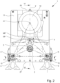
- FIG. 2 to 7 A further developed embodiment of a vibratory mill for at least two grinding jars oscillating in a horizontal position is shown, with grinding jar holders and grinding jars not shown.
- the vibratory mill has a multi-part pendulum drive 1, the basic structure of which is similar to the basic structure of the Fig. 1 shown pendulum drive 1. Components of the same design and/or function as those shown in the Figures 1 to 7 The pendulum drives 1 shown are marked with the same reference numerals.
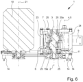
- the pendulum drive 1 of the Figures 2 to 7 The vibratory mill shown also has a vertical eccentric axis 2, around which an eccentric shaft 3 is rotatably mounted. Furthermore, two rockers 8, 9 are provided for holding grinding bowls, wherein the rockers 8, 9 can be connected to grinding bowl holders (not shown). The rockers 8, 9 are connected via ball bearings 17 ( Fig. 5 ) are held on bearing pins 12, 13 so that they can rotate about vertical swing axes 4, 5. In addition, the swing arms 8, 9 are connected via couplers 6, 7 ( Fig. 7 ) with the eccentric shaft 3. The couplers 6, 7 are rotatable or pivotable on bolts 19, 20 ( Fig. 7 ) of the rockers 8, 9 and on eccentrics 19a, 20a of the eccentric shaft 3.
- a motor unit 10 is provided to drive the eccentric shaft 3, wherein a motor shaft 10a is connected via a V-belt 18 ( Fig. 4 ) on the underside of the pendulum drive 1 transmits a torque to the eccentric shaft 3.
- the eccentric shaft 3, the bearing pins 12, 13 with the rockers 8, 9, the motor unit 10, and other components of the pendulum drive 1 are mounted or supported on a base plate 11.
- the base plate 11 rests on a base part (not shown) of the vibratory mill or on a substrate via damping elements 14, for example, rubber/spring elements.
- the pendulum drive 1 thus comprises, in particular, the eccentric shaft 3 and its bearing parts, the rockers 8, 9 and their bearing parts, the couplers 6, 7, the motor unit 10, the base plate 11, and possibly other components.
- the mixing and/or homogenization result of the grinding process in particular with regard to a particle size distribution that is as uniform as possible in grinding jars held on different rockers 8, 9, in particular with short grinding times of less than 120 s, preferably less than 60 s, more preferably less than 30 sec, for example with a grinding time of 10 s, the grinding process described in the Figures 2 to 7 shown vibrating mill, which is schematically shown Fig. 2
- the center of gravity SP of the pendulum drive 1 shown is to be specified by arranging the components of the pendulum drive 1 in such a way that the center of gravity SP is equidistant from both oscillation axes 4, 5.
- the rockers 8, 9 are arranged mirror-symmetrically to the eccentric shaft 3 and the motor unit 10, with the center of gravity SP of the pendulum drive 1 lying on the axis of symmetry Y.
- the eccentric axis 2 and the vertical axis 21 through the center of gravity of the motor unit 10 also lie on the axis of symmetry Y.
- an isosceles triangle is spanned in a horizontal center of gravity plane by the center of gravity SP of the pendulum drive 1 and the oscillation axes 4, 5.
- the eccentric axis 2 intersects the median of the side line passing through the oscillation axes 4, 5 of the triangle spanned in the center of gravity plane by the center of gravity SP of the pendulum drive 1 and the oscillation axes 4, 5, preferably centrally.
- Fig. 2 that - as with the vibrating mill from Fig. 1 - the oscillation axes 4, 5 are arranged mirror-symmetrically to the eccentric axis 2 and their intersection points with the center of gravity plane form an isosceles triangle.
- the center of gravity SP of the pendulum drive 1 resulting from the mass, geometry and arrangement of the components of the pendulum drive 1 can be compared to the Fig. 2 shown position, where the center of gravity SP lies exactly on the symmetry axis Y, can also be shifted laterally relative to the symmetry axis Y in the direction of one of the oscillation axes 4, 5.
- the lateral distance a of the center of gravity SP of the pendulum drive 1 from the symmetry axis Y can be less than 20%, preferably less than 15%, more preferably less than 10%, particularly preferably less than 5%, of half the distance between the oscillation axes 4, 5.
- the center of gravity SP of the pendulum drive 1 can be positioned by arranging the motor unit 10 relative to the other components of the pendulum drive 1 such that vibrations of the base plate 11 are at least substantially compensated at the rear outer edge 26 of the base plate 11 facing the motor unit 10 and at the front outer edge 27 facing the rockers 8, 9.
- the center of gravity SP of the pendulum drive 1 is shifted in the direction of the eccentric axis 2 relative to the center point MP of the median of the triangle formed by the vertical axis 21 and the oscillation axes 4, 5 in the center of gravity plane.
- the distance b of the center of gravity SP of the pendulum drive 1 to the center point MP ( Fig. 2 ) of the side bisector may be less than 20%, preferably less than 15%, more preferably less than 10%, of half the length of the side bisector.
- the center of gravity SP of the pendulum drive 1 can in principle also be shifted relative to the center point MP in the direction of the vertical axis 21 passing through the center of gravity of the motor unit 10.
- the eccentric shaft 3 is mounted or held vertically in the area below and above the couplers 6, 7 via the base plate 11 on the one hand and a cross member 22 on the other hand.
- a rear support wall 23 and a front support wall 24 ( Fig. 6 ) is provided, via which the cross member 22 is connected to the base plate 11.
- the rockers 8, 9 are held and supported in the bearing structure via the bearing pins 12, 13.
- the bearings of the rockers 8, 9 on the bearing pins 12, 13 are preferably carried out via angular contact ball bearings 17 ( Fig. 5 ).
- the bearings of the couplers 6, 7 on the bolts 19, 20 can be carried out via needle bearings.
- the bearings of the couplers 6, 7 on the eccentric shaft 3 and the bearings of the eccentric shaft 3 on the base plate 11 and the cross member 22 are preferably carried out via deep groove ball bearings 25, which in Fig. 6 is shown.
Landscapes
- Food Science & Technology (AREA)
- Engineering & Computer Science (AREA)
- Chemical & Material Sciences (AREA)
- Health & Medical Sciences (AREA)
- Physics & Mathematics (AREA)
- Chemical Kinetics & Catalysis (AREA)
- Clinical Laboratory Science (AREA)
- Life Sciences & Earth Sciences (AREA)
- Analytical Chemistry (AREA)
- Biochemistry (AREA)
- General Health & Medical Sciences (AREA)
- General Physics & Mathematics (AREA)
- Immunology (AREA)
- Pathology (AREA)
- Crushing And Grinding (AREA)
Claims (10)
- Broyeur oscillant pour au moins deux godets de broyage exécutant des oscillations en position horizontale, avec un entraînement pendulaire (1) en plusieurs parties, l'entraînement pendulaire (1) comprenant au moins un arbre excentrique (3) monté à rotation autour d'un axe d'excentrique vertical (2), au moins deux godets de broyage (4, 5, 6, 7) montés chacun autour d'un axe d'oscillation vertical (4, 5) et reliées à l'arbre excentrique (3) par des accouplements (6, 7) pour le maintien des bols de broyage, une unité de moteur (10) couplée à l'arbre excentrique (3) comme entraînement pour l'arbre excentrique (3) et éventuellement d'autres composants, un mouvement de rotation de l'arbre excentrique (3) pouvant être transformé en un mouvement d'oscillation des balanciers (8, 9) par l'intermédiaire des accouplements (6, 7) et le centre de gravité de l'entraînement pendulaire (1) étant situé dans un plan horizontal de centre de gravité à une distance au moins sensiblement égale des deux axes d'oscillation (4, 5), caractérisé en ce que le centre de gravité de l'entraînement pendulaire (1) est situé entre l'axe vertical de centre de gravité de l'unité motrice (10) et l'axe d'excentrique (2).
- Broyeur oscillant selon la revendication 1, caractérisé en ce que l'unité de moteur (10), l'arbre excentrique (3) et les balanciers (8, 9) ainsi que, le cas échéant, d'autres composants de l'entraînement pendulaire (1) sont disposés et/ou montés sur une plaque de base commune (15) et forment, avec la plaque de base (15), un système capable d'osciller.
- Broyeur à balancier selon la revendication 1 ou 2, caractérisé en ce que les balanciers (8, 9) sont disposés de manière symétrique par rapport à l'unité de moteur (10) et/ou à l'arbre excentrique (3) et en ce que, de préférence, le centre de gravité de l'entraînement à balancier (1) se trouve sur l'axe de symétrie.
- Broyeur oscillant selon l'une des revendications précédentes, caractérisé en ce que le centre de gravité de l'entraînement pendulaire (1) et les axes d'oscillation (4, 5) forment un triangle, de préférence isocèle, dans le plan du centre de gravité.
- Broyeur oscillant selon l'une des revendications précédentes, caractérisé en ce que l'axe d'excentrique (2) coupe la bissectrice de la ligne latérale passant par les axes d'oscillation (4, 5) du triangle formé dans le plan du centre de gravité par le centre de gravité de l'entraînement pendulaire (1) et les axes d'oscillation (4, 5).
- Broyeur vibrant selon l'une des revendications précédentes, caractérisé en ce que les axes de vibration (4, 5) et un axe vertical (21) passant par le centre de gravité de l'unité motrice (10) forment un triangle isocèle dans le plan du centre de gravité.
- Broyeur oscillant selon l'une des revendications précédentes, caractérisé en ce que le centre de gravité de l'entraînement pendulaire (1) est situé sur la bissectrice de la ligne latérale passant par les axes d'oscillation (4, 5) du triangle formé dans le plan du centre de gravité par les axes d'oscillation (4, 5) et l'axe vertical (21) passant par le centre de gravité de l'unité motrice (10).
- Broyeur vibrant selon l'une des revendications précédentes, caractérisé en ce qu'une structure de palier en forme de cadre, de grille ou de bâti est prévue pour le montage de l'arbre de l'excentrique (3) et, de préférence, pour le montage des balanciers (8, 9).
- Broyeur vibrant selon l'une des revendications précédentes, caractérisé en ce qu'il est prévu un dispositif de réglage pour le réglage, de préférence automatique, de la position de l'unité motrice (10) et/ou de la position d'au moins un poids d'équilibrage.
- Procédé de broyage d'un produit à broyer avec un broyeur oscillant selon l'une des revendications précédentes, caractérisé en ce que l'unité de moteur (10) et/ou au moins un poids d'équilibrage de l'entraînement pendulaire (1) est déplacé et/ou décalé de telle sorte que le centre de gravité de l'entraînement pendulaire (1) est au moins sensiblement à la même distance des deux axes d'oscillation (4, 5) dans un plan horizontal du centre de gravité.
Applications Claiming Priority (3)
| Application Number | Priority Date | Filing Date | Title |
|---|---|---|---|
| DE102018113139 | 2018-06-01 | ||
| DE102019106915.7A DE102019106915A1 (de) | 2018-06-01 | 2019-03-19 | Schwingmühle und Verfahren zum Vermahlen eines Mahlgutes |
| PCT/EP2019/061622 WO2019228764A1 (fr) | 2018-06-01 | 2019-05-07 | Broyeur oscillant et procédé de broyage d'un produit à broyer |
Publications (3)
| Publication Number | Publication Date |
|---|---|
| EP3638423A1 EP3638423A1 (fr) | 2020-04-22 |
| EP3638423C0 EP3638423C0 (fr) | 2025-06-18 |
| EP3638423B1 true EP3638423B1 (fr) | 2025-06-18 |
Family
ID=66640941
Family Applications (1)
| Application Number | Title | Priority Date | Filing Date |
|---|---|---|---|
| EP19725934.4A Active EP3638423B1 (fr) | 2018-06-01 | 2019-05-07 | Broyeur oscillant et procédé de broyage d'un produit à broyer |
Country Status (5)
| Country | Link |
|---|---|
| US (1) | US11719605B2 (fr) |
| EP (1) | EP3638423B1 (fr) |
| CN (1) | CN212632877U (fr) |
| DE (1) | DE102019106915A1 (fr) |
| WO (1) | WO2019228764A1 (fr) |
Families Citing this family (8)
| Publication number | Priority date | Publication date | Assignee | Title |
|---|---|---|---|---|
| DE202021106883U1 (de) | 2020-12-30 | 2022-03-31 | Retsch Gmbh | Laborschwingmühle, Mahlgefäßhalterung und Mahlgefäß |
| CN113786903B (zh) * | 2021-09-13 | 2022-04-05 | 淮北矿业股份有限公司临涣选煤厂 | 智能化煤炭给料转运机构 |
| WO2023110237A1 (fr) | 2021-12-17 | 2023-06-22 | Retsch Gmbh | Broyeur vibrant de laboratoire, support de cuve de broyage et cuve de broyage |
| CN113952871B (zh) * | 2021-12-22 | 2022-03-22 | 深圳市博为医疗机器人有限公司 | 一种摇匀装置 |
| EP4324563A1 (fr) | 2022-08-18 | 2024-02-21 | Herzog Maschinenfabrik GmbH & Co. KG | Broyeur à boules vibrantes |
| USD1107247S1 (en) * | 2023-09-11 | 2025-12-23 | Retsch Gmbh | Laboratory mill |
| USD1106746S1 (en) | 2023-09-11 | 2025-12-23 | Retsch Gmbh | Homogenizer |
| USD1116149S1 (en) * | 2024-03-08 | 2026-03-03 | Retsch Gmbh | Laboratory mill |
Family Cites Families (2)
| Publication number | Priority date | Publication date | Assignee | Title |
|---|---|---|---|---|
| KR101237040B1 (ko) * | 2004-06-23 | 2013-02-25 | 베르뗑 떼끄놀로지 | 진동 운동하는 샤프트를 가이드하는 장치 |
| CN202447149U (zh) * | 2012-02-28 | 2012-09-26 | 天津天昶科技有限公司 | 一种高通量微量研磨机 |
-
2019
- 2019-03-19 DE DE102019106915.7A patent/DE102019106915A1/de active Pending
- 2019-05-07 EP EP19725934.4A patent/EP3638423B1/fr active Active
- 2019-05-07 CN CN201990000258.8U patent/CN212632877U/zh active Active
- 2019-05-07 WO PCT/EP2019/061622 patent/WO2019228764A1/fr not_active Ceased
- 2019-05-07 US US16/754,336 patent/US11719605B2/en active Active
Also Published As
| Publication number | Publication date |
|---|---|
| US11719605B2 (en) | 2023-08-08 |
| EP3638423A1 (fr) | 2020-04-22 |
| CN212632877U (zh) | 2021-03-02 |
| EP3638423C0 (fr) | 2025-06-18 |
| WO2019228764A1 (fr) | 2019-12-05 |
| DE102019106915A1 (de) | 2019-12-05 |
| US20200333219A1 (en) | 2020-10-22 |
Similar Documents
| Publication | Publication Date | Title |
|---|---|---|
| EP3638423B1 (fr) | Broyeur oscillant et procédé de broyage d'un produit à broyer | |
| EP1959244B1 (fr) | Dispositif de dosage doté d'une sonnette | |
| DE2003201C3 (de) | Aufbereitungs- und Mischmaschine | |
| EP0155527A2 (fr) | Dispositif pour le nettoyage des semoules | |
| EP2910312A1 (fr) | Agencement oscillatoire pour une table vibrante ou un dispositif de tamisage | |
| CH706410A1 (de) | Vorrichtung zur Extraktion von Analyten mit Mahlkugeln. | |
| DE102012009982A1 (de) | Laborkugelmühle | |
| DE202022003064U1 (de) | Planetenmühle | |
| DE3928872A1 (de) | Analysensiebgeraet | |
| DE102018103014B4 (de) | Vibrationsmühle und Mahlaufsatz für eine solche | |
| DE102018103013B4 (de) | Vibrationsmühle, Mahlgarnitur und Mahlkörper für solche | |
| DE202019101537U1 (de) | Schwingmühle | |
| EP2063993B1 (fr) | Broyeur oscillant avec rail de guidage | |
| DE102017111018B4 (de) | Streuanlage | |
| DE102014019139A1 (de) | Tiefenrüttler mit veränderbarer Unwucht | |
| DE2108181B2 (de) | Vorrichtung zum Aufbereiten, Mischen, Auflockern, Zerteilen oder Kühlen von körnigem Material, insbesondere Gießsand | |
| DE102023120599A1 (de) | Labormühle und Kalibriernormal für eine Labormühle | |
| DE102019134920B4 (de) | Aktivierungsmittel für Dosiervorrichtung | |
| DE1841635U (de) | Vibrationsvorrichtung. | |
| EP3415295B1 (fr) | Installation de diffusion | |
| WO2018098599A1 (fr) | Procédé et dispositif d'enlèvement par fraisage des matériaux rocheux ou des matériaux de type roche | |
| DE19923783A1 (de) | Siebvorrichtung | |
| DE2308307B2 (de) | Schwingsieb zum Sortieren von Gut unterschiedlicher Korngröße | |
| DE618432C (de) | Kollergang zur Behandlung von Giessereiformsand | |
| DE202022105879U1 (de) | Modulares Laborgerät |
Legal Events
| Date | Code | Title | Description |
|---|---|---|---|
| STAA | Information on the status of an ep patent application or granted ep patent |
Free format text: STATUS: UNKNOWN |
|
| STAA | Information on the status of an ep patent application or granted ep patent |
Free format text: STATUS: THE INTERNATIONAL PUBLICATION HAS BEEN MADE |
|
| PUAI | Public reference made under article 153(3) epc to a published international application that has entered the european phase |
Free format text: ORIGINAL CODE: 0009012 |
|
| STAA | Information on the status of an ep patent application or granted ep patent |
Free format text: STATUS: REQUEST FOR EXAMINATION WAS MADE |
|
| 17P | Request for examination filed |
Effective date: 20200115 |
|
| AK | Designated contracting states |
Kind code of ref document: A1 Designated state(s): AL AT BE BG CH CY CZ DE DK EE ES FI FR GB GR HR HU IE IS IT LI LT LU LV MC MK MT NL NO PL PT RO RS SE SI SK SM TR |
|
| AX | Request for extension of the european patent |
Extension state: BA ME |
|
| DAV | Request for validation of the european patent (deleted) | ||
| DAX | Request for extension of the european patent (deleted) | ||
| STAA | Information on the status of an ep patent application or granted ep patent |
Free format text: STATUS: EXAMINATION IS IN PROGRESS |
|
| 17Q | First examination report despatched |
Effective date: 20230310 |
|
| GRAP | Despatch of communication of intention to grant a patent |
Free format text: ORIGINAL CODE: EPIDOSNIGR1 |
|
| STAA | Information on the status of an ep patent application or granted ep patent |
Free format text: STATUS: GRANT OF PATENT IS INTENDED |
|
| INTG | Intention to grant announced |
Effective date: 20250401 |
|
| GRAS | Grant fee paid |
Free format text: ORIGINAL CODE: EPIDOSNIGR3 |
|
| GRAA | (expected) grant |
Free format text: ORIGINAL CODE: 0009210 |
|
| STAA | Information on the status of an ep patent application or granted ep patent |
Free format text: STATUS: THE PATENT HAS BEEN GRANTED |
|
| AK | Designated contracting states |
Kind code of ref document: B1 Designated state(s): AL AT BE BG CH CY CZ DE DK EE ES FI FR GB GR HR HU IE IS IT LI LT LU LV MC MK MT NL NO PL PT RO RS SE SI SK SM TR |
|
| REG | Reference to a national code |
Ref country code: GB Ref legal event code: FG4D Free format text: NOT ENGLISH |
|
| REG | Reference to a national code |
Ref country code: CH Ref legal event code: EP |
|
| REG | Reference to a national code |
Ref country code: DE Ref legal event code: R096 Ref document number: 502019013466 Country of ref document: DE |
|
| REG | Reference to a national code |
Ref country code: CH Ref legal event code: EP |
|
| REG | Reference to a national code |
Ref country code: IE Ref legal event code: FG4D Free format text: LANGUAGE OF EP DOCUMENT: GERMAN |
|
| U01 | Request for unitary effect filed |
Effective date: 20250707 |
|
| U07 | Unitary effect registered |
Designated state(s): AT BE BG DE DK EE FI FR IT LT LU LV MT NL PT RO SE SI Effective date: 20250711 |
|
| PG25 | Lapsed in a contracting state [announced via postgrant information from national office to epo] |
Ref country code: NO Free format text: LAPSE BECAUSE OF FAILURE TO SUBMIT A TRANSLATION OF THE DESCRIPTION OR TO PAY THE FEE WITHIN THE PRESCRIBED TIME-LIMIT Effective date: 20250918 Ref country code: GR Free format text: LAPSE BECAUSE OF FAILURE TO SUBMIT A TRANSLATION OF THE DESCRIPTION OR TO PAY THE FEE WITHIN THE PRESCRIBED TIME-LIMIT Effective date: 20250919 |
|
| PG25 | Lapsed in a contracting state [announced via postgrant information from national office to epo] |
Ref country code: HR Free format text: LAPSE BECAUSE OF FAILURE TO SUBMIT A TRANSLATION OF THE DESCRIPTION OR TO PAY THE FEE WITHIN THE PRESCRIBED TIME-LIMIT Effective date: 20250618 |
|
| PG25 | Lapsed in a contracting state [announced via postgrant information from national office to epo] |
Ref country code: RS Free format text: LAPSE BECAUSE OF FAILURE TO SUBMIT A TRANSLATION OF THE DESCRIPTION OR TO PAY THE FEE WITHIN THE PRESCRIBED TIME-LIMIT Effective date: 20250918 |
|
| PG25 | Lapsed in a contracting state [announced via postgrant information from national office to epo] |
Ref country code: IS Free format text: LAPSE BECAUSE OF FAILURE TO SUBMIT A TRANSLATION OF THE DESCRIPTION OR TO PAY THE FEE WITHIN THE PRESCRIBED TIME-LIMIT Effective date: 20251018 |
|
| PG25 | Lapsed in a contracting state [announced via postgrant information from national office to epo] |
Ref country code: SM Free format text: LAPSE BECAUSE OF FAILURE TO SUBMIT A TRANSLATION OF THE DESCRIPTION OR TO PAY THE FEE WITHIN THE PRESCRIBED TIME-LIMIT Effective date: 20250618 |
|
| PG25 | Lapsed in a contracting state [announced via postgrant information from national office to epo] |
Ref country code: CZ Free format text: LAPSE BECAUSE OF FAILURE TO SUBMIT A TRANSLATION OF THE DESCRIPTION OR TO PAY THE FEE WITHIN THE PRESCRIBED TIME-LIMIT Effective date: 20250618 |
|
| PG25 | Lapsed in a contracting state [announced via postgrant information from national office to epo] |
Ref country code: PL Free format text: LAPSE BECAUSE OF FAILURE TO SUBMIT A TRANSLATION OF THE DESCRIPTION OR TO PAY THE FEE WITHIN THE PRESCRIBED TIME-LIMIT Effective date: 20250618 |
|
| PG25 | Lapsed in a contracting state [announced via postgrant information from national office to epo] |
Ref country code: SK Free format text: LAPSE BECAUSE OF FAILURE TO SUBMIT A TRANSLATION OF THE DESCRIPTION OR TO PAY THE FEE WITHIN THE PRESCRIBED TIME-LIMIT Effective date: 20250618 |
|
| PG25 | Lapsed in a contracting state [announced via postgrant information from national office to epo] |
Ref country code: ES Free format text: LAPSE BECAUSE OF FAILURE TO SUBMIT A TRANSLATION OF THE DESCRIPTION OR TO PAY THE FEE WITHIN THE PRESCRIBED TIME-LIMIT Effective date: 20250618 |
|
| PLBE | No opposition filed within time limit |
Free format text: ORIGINAL CODE: 0009261 |
|
| STAA | Information on the status of an ep patent application or granted ep patent |
Free format text: STATUS: NO OPPOSITION FILED WITHIN TIME LIMIT |
|
| REG | Reference to a national code |
Ref country code: CH Ref legal event code: L10 Free format text: ST27 STATUS EVENT CODE: U-0-0-L10-L00 (AS PROVIDED BY THE NATIONAL OFFICE) Effective date: 20260430 |