EP3638460B1 - Dispositif de localisation pour un point d'usinage sur une pièce à usiner - Google Patents
Dispositif de localisation pour un point d'usinage sur une pièce à usiner Download PDFInfo
- Publication number
- EP3638460B1 EP3638460B1 EP18733222.6A EP18733222A EP3638460B1 EP 3638460 B1 EP3638460 B1 EP 3638460B1 EP 18733222 A EP18733222 A EP 18733222A EP 3638460 B1 EP3638460 B1 EP 3638460B1
- Authority
- EP
- European Patent Office
- Prior art keywords
- workpiece
- frame
- measuring
- measuring equipment
- movement
- Prior art date
- Legal status (The legal status is an assumption and is not a legal conclusion. Google has not performed a legal analysis and makes no representation as to the accuracy of the status listed.)
- Active
Links
Images




Classifications
-
- B—PERFORMING OPERATIONS; TRANSPORTING
- B25—HAND TOOLS; PORTABLE POWER-DRIVEN TOOLS; MANIPULATORS
- B25H—WORKSHOP EQUIPMENT, e.g. FOR MARKING-OUT WORK; STORAGE MEANS FOR WORKSHOPS
- B25H1/00—Work benches; Portable stands or supports for positioning portable tools or work to be operated on thereby
- B25H1/0021—Stands, supports or guiding devices for positioning portable tools or for securing them to the work
- B25H1/0057—Devices for securing hand tools to the work
- B25H1/0064—Stands attached to the workpiece
- B25H1/0071—Stands attached to the workpiece by magnetic means
-
- B—PERFORMING OPERATIONS; TRANSPORTING
- B25—HAND TOOLS; PORTABLE POWER-DRIVEN TOOLS; MANIPULATORS
- B25H—WORKSHOP EQUIPMENT, e.g. FOR MARKING-OUT WORK; STORAGE MEANS FOR WORKSHOPS
- B25H1/00—Work benches; Portable stands or supports for positioning portable tools or work to be operated on thereby
- B25H1/0021—Stands, supports or guiding devices for positioning portable tools or for securing them to the work
- B25H1/0057—Devices for securing hand tools to the work
- B25H1/0064—Stands attached to the workpiece
-
- B—PERFORMING OPERATIONS; TRANSPORTING
- B23—MACHINE TOOLS; METAL-WORKING NOT OTHERWISE PROVIDED FOR
- B23Q—DETAILS, COMPONENTS, OR ACCESSORIES FOR MACHINE TOOLS, e.g. ARRANGEMENTS FOR COPYING OR CONTROLLING; MACHINE TOOLS IN GENERAL CHARACTERISED BY THE CONSTRUCTION OF PARTICULAR DETAILS OR COMPONENTS; COMBINATIONS OR ASSOCIATIONS OF METAL-WORKING MACHINES, NOT DIRECTED TO A PARTICULAR RESULT
- B23Q17/00—Arrangements for observing, indicating or measuring on machine tools
- B23Q17/002—Arrangements for observing, indicating or measuring on machine tools for indicating or measuring the holding action of work or tool holders
- B23Q17/003—Arrangements for observing, indicating or measuring on machine tools for indicating or measuring the holding action of work or tool holders by measuring a position
-
- G—PHYSICS
- G01—MEASURING; TESTING
- G01B—MEASURING LENGTH, THICKNESS OR SIMILAR LINEAR DIMENSIONS; MEASURING ANGLES; MEASURING AREAS; MEASURING IRREGULARITIES OF SURFACES OR CONTOURS
- G01B11/00—Measuring arrangements characterised by the use of optical techniques
- G01B11/14—Measuring arrangements characterised by the use of optical techniques for measuring distance or clearance between spaced objects or spaced apertures
-
- B—PERFORMING OPERATIONS; TRANSPORTING
- B23—MACHINE TOOLS; METAL-WORKING NOT OTHERWISE PROVIDED FOR
- B23Q—DETAILS, COMPONENTS, OR ACCESSORIES FOR MACHINE TOOLS, e.g. ARRANGEMENTS FOR COPYING OR CONTROLLING; MACHINE TOOLS IN GENERAL CHARACTERISED BY THE CONSTRUCTION OF PARTICULAR DETAILS OR COMPONENTS; COMBINATIONS OR ASSOCIATIONS OF METAL-WORKING MACHINES, NOT DIRECTED TO A PARTICULAR RESULT
- B23Q17/00—Arrangements for observing, indicating or measuring on machine tools
- B23Q17/20—Arrangements for observing, indicating or measuring on machine tools for indicating or measuring workpiece characteristics, e.g. contour, dimension, hardness
-
- B—PERFORMING OPERATIONS; TRANSPORTING
- B23—MACHINE TOOLS; METAL-WORKING NOT OTHERWISE PROVIDED FOR
- B23Q—DETAILS, COMPONENTS, OR ACCESSORIES FOR MACHINE TOOLS, e.g. ARRANGEMENTS FOR COPYING OR CONTROLLING; MACHINE TOOLS IN GENERAL CHARACTERISED BY THE CONSTRUCTION OF PARTICULAR DETAILS OR COMPONENTS; COMBINATIONS OR ASSOCIATIONS OF METAL-WORKING MACHINES, NOT DIRECTED TO A PARTICULAR RESULT
- B23Q17/00—Arrangements for observing, indicating or measuring on machine tools
- B23Q17/22—Arrangements for observing, indicating or measuring on machine tools for indicating or measuring existing or desired position of tool or work
- B23Q17/2291—Arrangements for observing, indicating or measuring on machine tools for indicating or measuring existing or desired position of tool or work for adjusting the workpiece relative to the holder thereof
-
- G—PHYSICS
- G01—MEASURING; TESTING
- G01B—MEASURING LENGTH, THICKNESS OR SIMILAR LINEAR DIMENSIONS; MEASURING ANGLES; MEASURING AREAS; MEASURING IRREGULARITIES OF SURFACES OR CONTOURS
- G01B21/00—Measuring arrangements or details thereof, where the measuring technique is not covered by the other groups of this subclass, unspecified or not relevant
- G01B21/02—Measuring arrangements or details thereof, where the measuring technique is not covered by the other groups of this subclass, unspecified or not relevant for measuring length, width, or thickness
- G01B21/04—Measuring arrangements or details thereof, where the measuring technique is not covered by the other groups of this subclass, unspecified or not relevant for measuring length, width, or thickness by measuring coordinates of points
- G01B21/047—Accessories, e.g. for positioning, for tool-setting, for measuring probes
-
- G—PHYSICS
- G01—MEASURING; TESTING
- G01B—MEASURING LENGTH, THICKNESS OR SIMILAR LINEAR DIMENSIONS; MEASURING ANGLES; MEASURING AREAS; MEASURING IRREGULARITIES OF SURFACES OR CONTOURS
- G01B5/00—Measuring arrangements characterised by the use of mechanical techniques
- G01B5/0002—Arrangements for supporting, fixing or guiding the measuring instrument or the object to be measured
- G01B5/0004—Supports
-
- G—PHYSICS
- G01—MEASURING; TESTING
- G01B—MEASURING LENGTH, THICKNESS OR SIMILAR LINEAR DIMENSIONS; MEASURING ANGLES; MEASURING AREAS; MEASURING IRREGULARITIES OF SURFACES OR CONTOURS
- G01B7/00—Measuring arrangements characterised by the use of electric or magnetic techniques
- G01B7/14—Measuring arrangements characterised by the use of electric or magnetic techniques for measuring distance or clearance between spaced objects or spaced apertures
-
- G—PHYSICS
- G01—MEASURING; TESTING
- G01D—MEASURING NOT SPECIALLY ADAPTED FOR A SPECIFIC VARIABLE; ARRANGEMENTS FOR MEASURING TWO OR MORE VARIABLES NOT COVERED IN A SINGLE OTHER SUBCLASS; TARIFF METERING APPARATUS; MEASURING OR TESTING NOT OTHERWISE PROVIDED FOR
- G01D5/00—Mechanical means for transferring the output of a sensing member; Means for converting the output of a sensing member to another variable where the form or nature of the sensing member does not constrain the means for converting; Transducers not specially adapted for a specific variable
- G01D5/12—Mechanical means for transferring the output of a sensing member; Means for converting the output of a sensing member to another variable where the form or nature of the sensing member does not constrain the means for converting; Transducers not specially adapted for a specific variable using electric or magnetic means
- G01D5/14—Mechanical means for transferring the output of a sensing member; Means for converting the output of a sensing member to another variable where the form or nature of the sensing member does not constrain the means for converting; Transducers not specially adapted for a specific variable using electric or magnetic means influencing the magnitude of a current or voltage
- G01D5/16—Mechanical means for transferring the output of a sensing member; Means for converting the output of a sensing member to another variable where the form or nature of the sensing member does not constrain the means for converting; Transducers not specially adapted for a specific variable using electric or magnetic means influencing the magnitude of a current or voltage by varying resistance
- G01D5/165—Mechanical means for transferring the output of a sensing member; Means for converting the output of a sensing member to another variable where the form or nature of the sensing member does not constrain the means for converting; Transducers not specially adapted for a specific variable using electric or magnetic means influencing the magnitude of a current or voltage by varying resistance by relative movement of a point of contact or actuation and a resistive track
-
- B—PERFORMING OPERATIONS; TRANSPORTING
- B23—MACHINE TOOLS; METAL-WORKING NOT OTHERWISE PROVIDED FOR
- B23Q—DETAILS, COMPONENTS, OR ACCESSORIES FOR MACHINE TOOLS, e.g. ARRANGEMENTS FOR COPYING OR CONTROLLING; MACHINE TOOLS IN GENERAL CHARACTERISED BY THE CONSTRUCTION OF PARTICULAR DETAILS OR COMPONENTS; COMBINATIONS OR ASSOCIATIONS OF METAL-WORKING MACHINES, NOT DIRECTED TO A PARTICULAR RESULT
- B23Q2716/00—Equipment for precise positioning of tool or work into particular locations
-
- B—PERFORMING OPERATIONS; TRANSPORTING
- B23—MACHINE TOOLS; METAL-WORKING NOT OTHERWISE PROVIDED FOR
- B23Q—DETAILS, COMPONENTS, OR ACCESSORIES FOR MACHINE TOOLS, e.g. ARRANGEMENTS FOR COPYING OR CONTROLLING; MACHINE TOOLS IN GENERAL CHARACTERISED BY THE CONSTRUCTION OF PARTICULAR DETAILS OR COMPONENTS; COMBINATIONS OR ASSOCIATIONS OF METAL-WORKING MACHINES, NOT DIRECTED TO A PARTICULAR RESULT
- B23Q2717/00—Arrangements for indicating or measuring
Definitions
- the present invention relates to devices for determining location on a workpiece.
- the beams may vary in dimensions and the schematics might not correspond to the actual beam dimensions that further decreases the accuracy of the measured points.
- machining such as drilling, coping or welding takes place at the measured points or lines.
- fastening devices such as magnetic capabilities in the drill or a dedicated workstand is used to secure the machining device directly on to the beam.
- the fastening means to secure a machining device on the workpiece vary. To some degree the material of the workpiece determines some of the means that may be used. However, attaching the device to the beam after the measurement has been done has a potential for further decrease in accuracy of the final machined hole in relation to the schematics. The user of the machine has to place the machine correctly and accurately in relation to the beam so that the right hole is bored but also so that the machine is securely fastened to the workpiece so that it doesn't move. Again due to the extent of manual effort this creates long process before the actual machining is done and additionally the process has many steps and techniques that cause potential for inaccuracy.
- CNC Computerized Numerical Control
- the objective is to at least alleviate the problems described hereinabove not satisfactorily solved by the known arrangements, and to provide a feasible solution for manually operable locationing device for a workpiece.
- the main advantage of the device in accordance with the present invention is that it comprises all the necessary measuring means incorporated in the device itself. This has a benefit of easier use and the solution is hence less prone to user error and inaccuracy.
- One further advantage of the device in accordance with the present invention is that the arrangement is completely manually operable and that it may be quickly moved from workpiece to another and calibrated in relation to the workpiece.
- a further advantage of the present invention is that it allows for accuracy that is sufficient in regards to relevant workpiece measuring and machining standards for a wide range of measured distances. This is an important advantage when working with e.g. elongated workpieces such as beams and girders that may require both small distance and longer distance measurements wherein the accuracy of those measurements should stay in the tolerances set by relevant standards.
- the present invention is preferably aimed at elongated workpieces but its features and the core invention may encompass also other shapes as is clear to a person skilled in the art.
- the technical effect of the present invention is that a user can place the device on any longitudinal workpiece, such as an I-beam or an H-beam, position the device on the workpiece by fixing the the device to the sides to the workpiece with the positioning means, and manually move the device on the workpiece and do measurements at the device itself in relation to the workpiece without moving said workpiece, which workpieces are usually heavy and require a lot of space for movement and often motor-assistance.
- any longitudinal workpiece such as an I-beam or an H-beam
- a device for determining a location on an elongated workpiece and being manually movable on the workpiece comprising:
- the device further comprises second movable means for moving the measuring point perpendicularly in relation to the workpiece.
- the measuring equipment comprises at least one laser distance meter for measuring the longitudinal distance to a point of reference such as one end of the elongated workpiece.
- the measuring equipment comprises at least two laser distance meters for measuring the distance to two points of references preferably on opposite sides of the frame.
- the point of reference comprises a counterpart for reflecting a laser beam of the laser distance meter.
- the measuring equipment comprises an optical sensor for measuring movement in the second direction, which optical sensor detects distance by moving linearly with the movable means in the transverse direction in relation to a surface of the frame of the device and/or surface of the workpiece.
- the measuring equipment comprises a magnetic sensor for measuring movement in the second direction, which magnetic sensor detects distance by moving linearly with the movable means in the transverse direction in relation and in connection with a magnetic strip on the frame of the device.
- the measuring equipment comprises an optical sensor for measuring movement in the second direction, which optical sensor detects distance from rotational movement of a leadscrew used to move the movable means.
- the device comprises attachment means for attaching tools to the frame.
- the attachment means may comprise a cradle with friction grip support for a magnetic drill.
- the attachment means may comprise a cradle and band attachment means for facilitating a magnetic drill.
- the attachement means may also comprise a cradle with some other friction grip means for gripping onto the tool or the cradle may comprise physical structures that carry the weight of the tool thereon.
- the cradle may comprise rolling sphere units facilitating movement and load transfer between the workpiece and the tool on the cradle.
- the measuring point comprises a center punch and/or allows the use of a center punch, preferably through a hole.
- the measuring equipment comprises an angle sensor, preferably functionally connected to the attachment means, for determining the position of the attached tool.
- the positioning means comprise rolls facilitating longitudinal movement of the frame.
- the measuring equipment comprises pulse sensors functionally connected at the rolls of the positioning means for measuring the longitudinal movement of the frame on the workpiece. This measurement may be used together with the laser distance measurement for more accurately measuring the longitudinal movement and the position of the frame on the workpiece
- the device comprises rolling means at the bottom of the frame facilitating longitudinal movement of the frame.
- the measuring equipment comprises pulse sensors at the rolling means for measuring the longitudinal movement of the frame on the workpiece.
- the device comprises a user interface such as a display for reading the measured value.
- a number of refers herein to any positive integer starting from one (1), e.g. to one, two, or three.
- a plurality of refers herein to any positive integer starting from two (2), e.g. to two, three, or four.
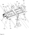
- the device 100 comprises a frame 102 that is movable in a first direction, preferably the longitudinal direction of an elongated workpiece such as a bar or I-beam ( Figs. 1b and 1c ) or an H-beam ( Fig. 1d ).
- the device 100 further comprises first movable means 104 connected to the frame 102 for facilitating transverse movement with respect to the workpiece and the frame 102.
- the device 100 further comprises positioning means 106 for fixing the frame 102 to the workpiece.
- a measuring point 108 is connected to the movable means 104.
- the device 100 also comprises measuring equipment 110a, 110b, 110c, 110d, 110e for determining the location of the measuring point 108.
- the first movable means 104 comprises preferably an arrangement that moves in relation to the frame 102 and the workpiece such as that the measuring point 108 moves in a transverse direction. Therefore the movable means 104 constitutes a moving support for the measuring point 108 and the other one or more tools that may be attached to the device 100.
- the movable means 104 hence is a tool support part of the device 100. Because the movable means 104 is movable in relation to the frame 102 the measuring point 108 or other tool thereof location may be adjusted in a transverse direction without having to move the whole device 100.
- the frame 102 may comprise e.g. linear tracks on which the movable means 104 may move in a fixed manner in relation to the frame 102.
- the transverse movement may be facilitated by a leadscrew or drive screw, which may be turned by a turning knob or the like at one end of the leadscrew or drive screw.
- the first movable means are preferably arranged to move the measuring point 108 in transverse direction, such as that movement in longitudinal direction is not connected to the transverse movement.
- the first movable means 104 may also comprise at least one rolling knob 113 and arrangement thereof for fine adjusting the transverse position.
- the rolling knob 113 may be arranged to be movable against the casing of the device 100 e.g. with fingers.
- the one or more rolling knobs 113 may be arranged to only come into contact with the casing when pressed down (e.g. by 1 mm) so the fine adjustment may be done by first pressing the rolling knob down and then rolling the knob with fingers.
- the device may also comprise second movable means 109 for moving the measuring point vertically in relation to the workpiece surface, preferably perpendicularly closer or farther from the workpiece surface.
- the measuring equipment 110a, 110b, 110c, 110d, 110d needn't necessarily comprise means for determining the vertical distance from the device to the workpiece surface because the measurements for a girder or such workpiece are usually done in relation to the workpiece two-dimensional surface. This way the second movable means may be simply used to get closer to a workpiece surface in relation to the point determined in first and second directions as depicted in figure 1d .
- the second movable means 109 are preferably connected to the first movable means 104 so that the second movable means 109 and consequently the measuring point 108 are moved horizontally in relation to the workpiece when the first movable means 104 are moved.
- the second movable 109 means may comprise linear tracks for moving linearly closed or farther from the workpiece surface.
- the positioning means 106 enable fixing the device 100 to the workpiece at the sides of the workpiece.
- the positioning means 106 comprise for example rolls that are moved against the sides of the workpiece wherein the movement is arranged such that they move in symmetrically outwards or towards the sides of the workpiece.
- the positioning means are used to fix and position the device 100 to the workpiece such as that the device 100 may be moved in the first direction in relation to the workpiece but preferably also such that the device 100 is hindered from freely moving in the transverse direction in relation to the workpiece.
- the movement in first direction is preferably facilitated by using four rolls for two sides of the workpiece as illustrated.
- the positioning means 106 may be controlled by a leadscrew or a drive screw which may be controlled by a turning knob 107 or the like at one end of the screw of the positioning means 106.
- the positioning means 106 may be controlled by two interconnected drive screws which may be controlled by a turning knob 111 or the like at one end of the screws of the positioning means 106.
- the drive screws are preferably arranged such that the other has a right-hand helix and the other left-hand helix such as that the positioning means 106 moves synchronously from both sides of the device 100 to either tighten to or to release from workpiece sides.
- the positioning means 106 may also comprise a strap between two rolls at each one side of the device. This strap may allow the positioning means 106 to be moved synchronously also in the longitudinal direction such that two rolls at each side move against the workpiece synchronously or that the strap attaches to the side of the workpiece and delivers the movement between the side of the workpiece and the rolls.
- the strap may be looped around the rolls.
- the measuring point 108 constitutes a point whose location is moved by moving the device 100 on the workpiece.
- the location of the measuring point 108 is measured directly or it is used as a reference point in relation to which measurements may be made.
- the measuring point 108 may comprise a center punch for marking a point in the workpiece.
- the center point may be the center of a drill hole, for example.
- the measuring point 108 comprises a hole for a center punch, and a separate center punch or pen may be used to mark a center point through the hole.
- the measuring point 108 may hence comprise a physical point of the device or a reference point to which a measured point or line may be defined.
- the device 100 further comprises longitudinal measuring equipment 110a for determining the longitudinal location of the measuring point 108 with respect to the workpiece.
- the longitudinal distance is preferably measured from one end of the workpiece in relation to the reference point 108.
- the longitudinal measuring equipment 110a may comprise a laser distance meter measuring the distance to a point of reference such as the longitudinal end of the workpiece.
- the laser distance meter may be arranged in the frame 102 wherein the laser equipment is situated at the frame such that the measurement may be done unobstructed by the dimensions of the device 100.
- the laser distance meter is preferably a component that may be connected to the processor of the device.
- the laser distance meter may be a dedicated measurement device that has a processor of its own to measure the longitudinal distance.
- the measuring equipment may be situated in many different locations of the device 100 and the calculation of the measuring point 108 in relation to the measuring equipment reading may be done internally in the device in view of the device 100 configuration, dimensions, etc.
- a counterpart may be arranged to a point of reference so that the laser beam is reflected from the counterpart.
- a counterpart may be arranged at the end of the workpiece so that the laser distance meter measures the distance to that end of the workpiece.
- the device 100 may comprise at least two laser distance meters that measure the distance to at least two reference points. Therein the two laser distance meters may be located on opposite sides of the frame 102.
- the two reference points may be located in each end of the workpiece so that the at least two distance meters measures the distance to each end.
- the counterpart may be such that almost any surface or object induced reflection is suitable and hence no particular reflection surface is required.
- a dedicated counterpart is not mandatory to the functioning of the device although it may be used to improve the accuracy of the measurements done with the device.
- a white-colored surface of the counterpart may be used improve the accuracy of the longitudinal measurement.
- a wall of a building another beam, such as an intersection of beams or a bend at the beam, or a point at a stand whereon the workpiece is laid may be used for facilitating reflection for the laser device measurements.
- the measuring equipment for determining the longitudinal distance and location may comprise mechanical tape measure roll wherein measuring is done at the device 100 but the tape may be drawn to the side or end(s) of the workpiece. Such means may also be used to determine the transverse distance from at least one side of the elongated workpiece.
- the device 100 may further comprise attachment means 112 for attaching tools to the device 100.
- the attachment means 112 may comprise a band arrangement 114 for facilitating grip around a tool.
- the attachement means may also comprise a cradle with some other friction grip means for gripping onto the tool or the cradle may comprise physical structures that carry the weight of the tool thereon.
- the cradle may comprise rolling sphere units facilitating movement and load transfer between the workpiece and the tool on the cradle.
- the tool may be a magnetic drill or an angle rule, for example.
- the attachment means 112 may comprise an angle sensor 116 (potentiometer) for determining the position of the attachment means 112 in relation to the frame 102 and consequently the location of the tool thereof.
- the angle sensor 116 may be arranged to determine the location of a magnetic drill bit and drilling point in relation to the measuring point 108. Therefore, the measuring point may be used as a point of reference such that the device 100 may directly determine a position for a tool and location thereof that is machined with the tool.
- the attachment means 112 may be pivotally attached to the movable means 104 so that the attachment means 112 are rotatable in relation to the workpiece. Therefore different tools may and measured locations thereof may be situated at the attachment means 112.
- a pin is used to connect the angle sensor and/or other measuring sensors and optionally the tool at the attachment means 112 thereof to the processor 124 of the device.
- the angle sensor 116 may be arranged to the device 100 or the device 100 may simply comprise means to connect to an external angle sensor such as an angle sensor in an tool cradle or jig that is attached to the device 100 at the attachment means 112.
- the attachment means 112 may comprise a band arrangement 114 or similar for facilitating a grip on a tool.
- the band may be for example nylon or polymer band that is fastened with a ratchet. This is especially suitable for a magnetic drill, which may be attached to the device 100 such as to move to a location to be drilled and after positioning the drill in relation to the point the magnet may be turned on the drill is instantly positioned to the right point.
- the attachment means 112 preferably also comprises rolling sphere units 120 that may comprise suspension for facilitating movement and load transfer between the workpiece and the tool on the cradle allowing the drill to be moved freely over the workpiece when the magnet is not turned on and to give in and allow the magnet drill to come into contact with the workpiece surface when the magnet of the magnetic drill is turned on.
- rolling sphere units 120 may comprise suspension for facilitating movement and load transfer between the workpiece and the tool on the cradle allowing the drill to be moved freely over the workpiece when the magnet is not turned on and to give in and allow the magnet drill
- solution is aimed at metal workpieces but solution is also usable for workpieces comprising other materials such as wood or polymer.
- the movable means 104 comprise a part that is moved in relation to the transverse direction of the workpiece.
- the movable means 104 is facilitated by the part moving via a drive screw or a leadscrew that is turned with a knob 105 at the end of the screw on either side of the frame 102 or by hand by pushing the movable means and/or fine adjusting with another knob 113.
- the transverse movement is measured preferably with an optical sensor 110c such a pulse sensor.
- the pulse sensor 110c may be situated at the end of the screw, such as that rotating the knob rotates a plate in between a pulse sensor 110c wherein the rotation may be measured as pulses and the pulses may be further translated into a measure of transverse movement.
- the pulse sensor may be arranged to the movable means 104 such as that the sensor 110c moves linearly with the movable means and measures its own location in reference to a surface of the frame or to the surface of the workpiece.
- the sensor 110c itself is in the moving part and the pulses are situated at a rail, track, leadscrew or a surface as mentioned before in relation to which the movable means move.
- the transverse movement may be optionally measured with a magnetic sensor arrangement such as a magnetic sensor 110d moving in relation and at least functional connection to a magnetic strip.
- the magnetic sensor 110d may be arranged to the movable means 104 such as that the sensor 110d moves linearly with the movable means 104 and measures its movement in reference to the magnetic strip on the frame 102 surface. Therein the magnetic sensor 110d itself is in the moving part and the magnetic strip is fixed on the frame 102 surface so that the magnetic sensor travels against the magnetic strip when the movable means 104 are moved.
- the positioning means 106 are preferably moved by a trapezoidal leadscrew or a drive screw for moving the rolls against the workpiece therefore facilitating tight and secure fixing of the frame 102 in relation to the workpiece.
- the rolls facilitate both fixing of the frame to workpiece and moving the frame 102 in relation to the workpiece.
- the positioning of the frame to the workpiece is preferably done sufficiently tight to the workpiece such as not to allow slack movement in transverse direction. For this purpose ratchet or such tightening means may be used.
- a spring coupling arrangement may be used such that the lever or knob 111 used to turn the screw 130 can be drawn out or put in for coupling with the screw 130, which enables the positioning means 106 to be used also by hand when the knob or lever 111 is not coupled to the screw.
- the lever or knob is pressed in the same (transverse) direction, whereby e.g. toothed disc clutches connect the lever and the screw to each other for transmission of torque.
- a spring may be arranged between the lever and screw. The lever or knob 111 is rotated and locked in the tilted position and the spring provides resistance for the movement of the positioning means 106.
- the spring is pressed against the end of the screw and the knob or lever 111 of the positioning means 106 and the rolls of the positioning means 106 against the workpiece.
- the positioning means 106 are fixed by hand to a certain setting in relation to the workpiece because of the spring the rolls of the positioning means 106 may still move in a transverse direction in relation to the spring dimensions and force e.g. if the workpiece width varies when the device is moved longitudinally along the workpiece.
- the use of a pulse sensor 110b is incorporated to detect the specific width of the workpiece. Therein similar pulse sensor techniques may be used as with the sensor 110c of the movable means 104.
- the positioning means 106 may also incorporate the use of a magnetic sensor 110e moving in relation and at least functional connection to a magnetic strip optionally the same magnetic strip as the one that the sensor 110d may use.
- the magnetic sensor 110e may be arranged to the movable means 104 such as that the sensor 110d moves linearly with the positioning means 106 and measures its movement in reference to the magnetic strip on the frame 102 surface. Therein the magnetic sensor 110e itself is in the moving part and the magnetic strip is fixed on the frame 102 surface so that the magnetic sensor travels against the magnetic strip when the movable means 104 are moved.
- the rolls of the positioning means 106 may comprise material or surface material that allows for tight grip to the workpiece and or flexibility thereof for dents, small peaks and such surface irregularities.
- the positioning means 106 may comprise springs, e.g. at the end of the leadscrew, or other such means for allowing flexibility in relation to the workpiece surface.
- the device 100 may also comprise other rolling means 118a, 118b at the bottom of the frame 102 for facilitating movement along the workpiece.
- the bottom rolls 118a, 118b may also comprise rolling sensors or optical sensors for measuring the rolling of the rolls which may be translated to a measure of distance in the longitudinal direction.
- the rolls of the positioning means 106 may comprise pulse sensor for tracking the rolling of one or more of the rolls or the movement of strap therein for determining the longitudinal movement of the device 100. This way the longitudinal movement may be optionally or additionally to the laser measurement also tracked at any of the mentioned rolls.
- the device 100 may hence read the longitudinal location and/or movement from two different measurement sources, which may be used to improve accuracy of the device 100.
- the bottom rolls may be operated with manual rotation of rotating transmission arrangement 103.
- the device 100 is manually operable to position and manually move the device in respect to a workpiece.
- the device 100 retains at least a certain standby mode such as that the reading of the pulse sensors stays in the memory and they needn't be calibrated every time when the device is used.
- the calibration may be done e.g. in relation to an end of the leadscrew or drive screw by moving the part to that extreme end of the screw.
- Every part of the electronics of the device haven't been explicitly depicted but they comprise at least a processor 124 to which the different sensors 110a, 110b, 110c, 110d, 110e, 116 are connected. Further the device 100 comprises a display 122 coupled with the processor 124 to facilitate displaying of the measurements and the location of the measuring point or the position of the tool at the attachment means 112 to the user.
- a top view, a cross-section view and another top view (with casing omitted) of the device is presented for further illustrating the device.
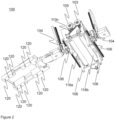
- the leadscrews and/or the drive screws 126, 128, 130 of the device 100 are shown.
- the device 100 may comprise two separate screws 126, 128 for moving the movable means 104 and the positioning means 106 on different screws or the device may comprise a single screw 130 for both the movable means 104 and the positioning means 106.
- the device 100 may comprise alternative location for the measuring point(s) 108a, 108b, which may also serve the purpose for attachment of different tools.
- the screw 126 is herein illustrated to be moving the movable means 104 which are further supported by rails on both sides of the frame 102.
- the screw 126 may be turned via a knob 105.
- the measuring point(s) 108a, 108b may be moved to a preferred location in transverse respect to the workpiece.
- the positioning means 106 are used to grip on to the workpiece at the sides of the workpiece.
- the gripping rolls of the positioning means 106 may be arranged to move in synchronicity towards or away from each other via turning the screw 128 by the knob 107.
- the movable means 104 and positioning means 106 may be arranged on a single shared screw 130, which is controlled by knob or lever 111 preferably with a spring coupling arrangement. Fine tuning of the longitudinal location may be done by turning of the knob 103 or pushing the device in a longitudinal direction, which both move the rolling means, i.e. the bottom rolls 118a, 118b and hence situate the measuring point(s) 108a, 108b in a longitudinal respect to the workpiece.
- a pulse sensor may be also arranged at the knob 103 to track the longitudinal movement.
Landscapes
- Physics & Mathematics (AREA)
- General Physics & Mathematics (AREA)
- Engineering & Computer Science (AREA)
- Mechanical Engineering (AREA)
- Length Measuring Devices With Unspecified Measuring Means (AREA)
- A Measuring Device Byusing Mechanical Method (AREA)
- Constituent Portions Of Griding Lathes, Driving, Sensing And Control (AREA)
- Attitude Control For Articles On Conveyors (AREA)
- Machine Tool Sensing Apparatuses (AREA)
Claims (15)
- Dispositif (100) de détermination d'une localisation sur une pièce à usiner allongée et qui est manuellement mobile sur la pièce à usiner, le dispositif (100) comprenant :- un cadre (102) mobile dans un premier sens, de préférence dans un sens longitudinal de la pièce à usiner, en déplaçant en conséquence l'ensemble du dispositif (100) sur la pièce à usiner dans ledit sens,- un moyen de positionnement (106) pour positionner le cadre (102) par rapport aux faces de la pièce à usiner, le moyen de positionnement (106) fixant le cadre (102) de manière à ce que le cadre (102) ne se déplace pas dans le second sens mais à ce que le cadre (102) puisse se déplacer dans le sens longitudinal de la pièce à usiner,- un moyen mobile (104) mobile dans un second sens, de préférence dans un sens transversal par rapport à la pièce à usiner et par rapport au cadre (102),- un point de mesure (108), le mouvement dans le premier sens et le second sens étant utilisé pour déplacer le point de mesure (108) dans lesdits sens,- le dispositif (100) comprenant un équipement de mesure (110a, 110b, 110c) pour déterminer la localisation du point de mesure (108) dans le sens transversal et longitudinal par rapport à la pièce à usiner,- l'équipement de mesure comprenant un équipement de mesure longitudinale (110a) pour déterminer la localisation longitudinale du point de mesure (108) par rapport à la pièce à usiner et à l'équipement de mesure (110c) pour déterminer le mouvement transversal du moyen mobile (104),- caractérisé en ce que l'équipement de mesure comprend un autre équipement de mesure (110b) en relation avec le moyen de positionnement (106) pour détecter la largeur spécifique de la pièce à usiner.
- Dispositif (100) selon la revendication 1, dans lequel l'équipement de mesure (110a, 110b, 110c) comprend au moins un mesureur de distance à laser pour mesurer la distance longitudinale jusqu'à un point de référence comme une extrémité de la pièce à usiner allongée.
- Dispositif (100) selon la revendication 1, dans lequel l'équipement de mesure (110a, 110b, 110c) comprend au moins deux mesureurs de distance à laser pour mesurer la distance longitudinale jusqu'à deux points de référence, de préférence sur des faces opposées du cadre.
- Dispositif (100) selon l'une quelconque des revendications précédentes, le dispositif (100) comprenant en outre un second moyen mobile (109) pour déplacer le point de mesure perpendiculairement à la pièce à usiner.
- Dispositif (100) selon l'une quelconque des revendications précédentes, dans lequel l'équipement de mesure (110a, 110b, 110c, 110d, 110e) comprend un capteur optique pour mesurer le mouvement dans le second sens, lequel capteur optique détecte la distance en se déplaçant linéairement avec le moyen mobile (104) dans le sens transversal par rapport à une surface du cadre (102) du dispositif (100) et/ou une surface de la pièce à usiner.
- Dispositif (100) selon l'une quelconque des revendications précédentes, dans lequel l'équipement de mesure (110a, 110b, 110c, 110d, 110e) comprend un capteur magnétique (110d) pour mesurer le mouvement dans le second sens, lequel capteur magnétique (110d) détecte la distance en se déplaçant linéairement avec le moyen mobile (104) dans le sens transversal en relation et en connexion avec une bande magnétique sur le cadre (102) du dispositif (100).
- Dispositif (100) selon l'une quelconque des revendications 1 à 6, dans lequel l'équipement de mesure (110a, 110b, 110c, 110d, 110e) comprend un capteur optique pour mesurer le mouvement dans le second sens, lequel capteur optique détecte la distance en partant du mouvement de rotation d'une vis mère ou d'une vis d'entraînement utilisée pour déplacer le moyen mobile (104).
- Dispositif (100) selon l'une quelconque des revendications précédentes, dans lequel le dispositif (100) comprend un moyen de fixation (112) pour fixer des outils au cadre (102).
- Dispositif (100) selon la revendication 8, dans lequel le moyen de fixation (112) comprend un berceau pour un outil.
- Dispositif (100) selon la revendication 8, dans lequel le moyen de fixation (112) comprend un moyen de fixation de berceau et de bande (114) pour faciliter un support de préhension pour une perceuse magnétique.
- Dispositif (100) selon l'une quelconque des revendications précédentes, dans lequel l'équipement de mesure (110a, 110b, 110c, 110d, 110e) comprend un capteur d'angle (116), de préférence connecté fonctionnellement au moyen de fixation (112), pour déterminer la position de l'outil fixé.
- Dispositif (100) selon l'une quelconque des revendications précédentes, dans lequel le moyen de positionnement (106) comprend des roulettes facilitant le mouvement longitudinal du cadre (102).
- Dispositif (100) selon la revendication 14, dans lequel l'équipement de mesure (110a, 110b, 110c) comprend des capteurs à impulsion connectés fonctionnellement aux roulettes du moyen de positionnement.
- Dispositif (100) selon l'une quelconque des revendications précédentes, comprenant un moyen de roulement au fond du cadre facilitant le mouvement longitudinal du cadre (102).
- Dispositif (100) selon la revendication 16, dans lequel l'équipement de mesure (110a, 110b, 110c) comprend des capteurs à impulsion au niveau du moyen de roulement de mesurer le mouvement longitudinal du cadre (102) sur la pièce à usiner.
Priority Applications (1)
| Application Number | Priority Date | Filing Date | Title |
|---|---|---|---|
| EP23212477.6A EP4425093A3 (fr) | 2017-06-16 | 2018-06-18 | Dispositif de positionnement pour une pièce à usiner |
Applications Claiming Priority (2)
| Application Number | Priority Date | Filing Date | Title |
|---|---|---|---|
| FI20175562A FI128698B (en) | 2017-06-16 | 2017-06-16 | Device for determining position with a workpiece |
| PCT/EP2018/066120 WO2018229298A1 (fr) | 2017-06-16 | 2018-06-18 | Dispositif de localisation pour un point d'usinage sur une pièce à usiner |
Related Child Applications (2)
| Application Number | Title | Priority Date | Filing Date |
|---|---|---|---|
| EP23212477.6A Division-Into EP4425093A3 (fr) | 2017-06-16 | 2018-06-18 | Dispositif de positionnement pour une pièce à usiner |
| EP23212477.6A Division EP4425093A3 (fr) | 2017-06-16 | 2018-06-18 | Dispositif de positionnement pour une pièce à usiner |
Publications (3)
| Publication Number | Publication Date |
|---|---|
| EP3638460A1 EP3638460A1 (fr) | 2020-04-22 |
| EP3638460C0 EP3638460C0 (fr) | 2024-04-10 |
| EP3638460B1 true EP3638460B1 (fr) | 2024-04-10 |
Family
ID=62705578
Family Applications (2)
| Application Number | Title | Priority Date | Filing Date |
|---|---|---|---|
| EP23212477.6A Pending EP4425093A3 (fr) | 2017-06-16 | 2018-06-18 | Dispositif de positionnement pour une pièce à usiner |
| EP18733222.6A Active EP3638460B1 (fr) | 2017-06-16 | 2018-06-18 | Dispositif de localisation pour un point d'usinage sur une pièce à usiner |
Family Applications Before (1)
| Application Number | Title | Priority Date | Filing Date |
|---|---|---|---|
| EP23212477.6A Pending EP4425093A3 (fr) | 2017-06-16 | 2018-06-18 | Dispositif de positionnement pour une pièce à usiner |
Country Status (8)
| Country | Link |
|---|---|
| US (1) | US11420317B2 (fr) |
| EP (2) | EP4425093A3 (fr) |
| CN (1) | CN111093902B (fr) |
| CA (1) | CA3067092C (fr) |
| ES (1) | ES2980800T3 (fr) |
| FI (1) | FI128698B (fr) |
| PL (1) | PL3638460T3 (fr) |
| WO (1) | WO2018229298A1 (fr) |
Families Citing this family (11)
| Publication number | Priority date | Publication date | Assignee | Title |
|---|---|---|---|---|
| FI128698B (en) * | 2017-06-16 | 2020-10-15 | Rock Roots Oy | Device for determining position with a workpiece |
| DE102019119484B4 (de) * | 2019-07-18 | 2025-03-20 | Benedikt Pfaff | Laser-Positionierungssystem zur Anordnung an Lochtischen |
| CN110653394B (zh) * | 2019-10-16 | 2025-05-27 | 国网河南省电力公司济源供电公司 | 一种孔距定位装置 |
| CN111375918A (zh) * | 2020-03-24 | 2020-07-07 | 盐城市同达机械科技有限公司 | 一种焊割设备 |
| CN114770437B (zh) * | 2022-05-05 | 2023-10-20 | 桂林航天工业学院 | 一种小型高精度移动平台 |
| FI20227153A1 (en) * | 2022-11-28 | 2024-05-29 | Rockroth Oy | Rolling element and arrangement |
| CN115781144A (zh) * | 2022-11-30 | 2023-03-14 | 中车常州车辆有限公司 | 一种自动焊接装置、自动焊接设备以及自动焊接方法 |
| CN116592815B (zh) * | 2023-07-17 | 2023-10-03 | 金乡县恒瑞钢化玻璃有限责任公司 | 一种钢化玻璃测量装置 |
| FI20235972A1 (en) * | 2023-08-31 | 2025-03-01 | Rockroth Oy | Locationing device for a workpiece |
| FI20235971A1 (en) * | 2023-08-31 | 2025-03-01 | Rockroth Oy | Locationing device for a workpiece |
| CN120314964B (zh) * | 2025-03-06 | 2026-04-21 | 苏州雷沃精工电梯有限公司 | 一种电梯层门定位装置 |
Family Cites Families (12)
| Publication number | Priority date | Publication date | Assignee | Title |
|---|---|---|---|---|
| FR2673133B1 (fr) * | 1991-02-27 | 1996-01-05 | Situb Sa | Machine mobile d'usinage sur chantier. |
| US6926094B2 (en) * | 2003-06-25 | 2005-08-09 | The Boeing Company | Apparatus for manufacturing operations using non-contact position sensing |
| JP2005300478A (ja) | 2004-04-15 | 2005-10-27 | Sunx Ltd | 光学測定装置 |
| US7216408B2 (en) * | 2004-05-27 | 2007-05-15 | The Boeing Company | Flexible rail multiaxis machine tool and method |
| US7112018B2 (en) * | 2005-01-19 | 2006-09-26 | The Boeing Company | Automatic position-locking tool carrier apparatus and method |
| FR2933323B1 (fr) * | 2008-07-01 | 2011-02-11 | Eads Europ Aeronautic Defence | Dispositif pour assister le positionnement d'outil par rapport a une piece |
| DE102008049821B4 (de) | 2008-10-01 | 2018-11-22 | Volkswagen Ag | Abstandssensor und Verfahren zur Ermittlung eines Abstands und/oder von Abstandsschwankungen zwischen einem Bearbeitungslaser und einem Werkstück |
| CN203471157U (zh) | 2013-09-20 | 2014-03-12 | 王锁弘 | 一种离心风机外壳自动焊接机 |
| JP6305195B2 (ja) | 2014-05-09 | 2018-04-04 | 株式会社アマダホールディングス | レーザ加工機及び加工原点補正方法 |
| CN204639766U (zh) * | 2015-05-19 | 2015-09-16 | 黄亮亮 | 一种钢轨切割机减震式轮式固定座装置 |
| CN105865355B (zh) | 2016-03-31 | 2019-06-14 | 昆山日制电机有限公司 | 非接触式零件外径测量装置 |
| FI128698B (en) * | 2017-06-16 | 2020-10-15 | Rock Roots Oy | Device for determining position with a workpiece |
-
2017
- 2017-06-16 FI FI20175562A patent/FI128698B/en active IP Right Grant
-
2018
- 2018-06-18 ES ES18733222T patent/ES2980800T3/es active Active
- 2018-06-18 CN CN201880050320.4A patent/CN111093902B/zh active Active
- 2018-06-18 US US16/622,714 patent/US11420317B2/en active Active
- 2018-06-18 CA CA3067092A patent/CA3067092C/fr active Active
- 2018-06-18 EP EP23212477.6A patent/EP4425093A3/fr active Pending
- 2018-06-18 EP EP18733222.6A patent/EP3638460B1/fr active Active
- 2018-06-18 WO PCT/EP2018/066120 patent/WO2018229298A1/fr not_active Ceased
- 2018-06-18 PL PL18733222.6T patent/PL3638460T3/pl unknown
Also Published As
| Publication number | Publication date |
|---|---|
| FI20175562A7 (fi) | 2018-12-17 |
| PL3638460T3 (pl) | 2024-07-29 |
| CA3067092A1 (fr) | 2018-12-20 |
| WO2018229298A1 (fr) | 2018-12-20 |
| EP3638460C0 (fr) | 2024-04-10 |
| CN111093902A (zh) | 2020-05-01 |
| FI128698B (en) | 2020-10-15 |
| EP3638460A1 (fr) | 2020-04-22 |
| CA3067092C (fr) | 2023-09-05 |
| FI20175562A1 (en) | 2018-12-17 |
| US11420317B2 (en) | 2022-08-23 |
| ES2980800T3 (es) | 2024-10-03 |
| EP4425093A3 (fr) | 2024-11-27 |
| EP4425093A2 (fr) | 2024-09-04 |
| CN111093902B (zh) | 2024-01-02 |
| US20200180137A1 (en) | 2020-06-11 |
Similar Documents
| Publication | Publication Date | Title |
|---|---|---|
| EP3638460B1 (fr) | Dispositif de localisation pour un point d'usinage sur une pièce à usiner | |
| MXPA06007221A (es) | Dispositivo y metodo para medir el perfil de una superficie. | |
| US7127824B2 (en) | Apparatus for detecting the position in space of a carriage moveable along a coordinate axis | |
| US20070220764A1 (en) | Precision electronic combination square | |
| US5219379A (en) | Angular alignment assembly | |
| CN105758317A (zh) | 一种可加工软质材料的三坐标测量机 | |
| US7937848B2 (en) | Coordinate measuring auxiliary tool, coordinate measuring probe and coordinate measuring machine | |
| JP2894825B2 (ja) | キー溝測定装置及びその使用方法 | |
| US6289595B1 (en) | Method and device for measuring workpieces having internal and/or external screw thread or similar grooves | |
| CN210689503U (zh) | 一种感栅位移传感器定栅间距的液压测量装置 | |
| US12504341B2 (en) | Test bench for checking the correct functioning of a tightening tool, such as a torque wrench | |
| US4554747A (en) | Convex radius gauge | |
| US10495436B2 (en) | Centerline and angle finder layout tool for cylindrical and radial surfaces | |
| WO2025046093A1 (fr) | Dispositif de localisation sur une pièce | |
| CN202420336U (zh) | 一种数显内径检测千分尺 | |
| CN220039308U (zh) | 一种不锈钢配管折弯尺寸检测工装 | |
| WO2025046085A1 (fr) | Dispositif de localisation pour pièce | |
| CN221695342U (zh) | 一种用于机械零件钻孔的定位检测结构 | |
| CN110231001A (zh) | 光学孔检测装置 | |
| RU2739043C1 (ru) | Измерительное устройство линейных перемещений ползуна с резцом расточной головки станка | |
| CN211453414U (zh) | 一种用于伽马射线无损检测的管道安装架 | |
| CA2998237A1 (fr) | Outil de disposition reperant l'angle et la ligne centrale destine aux surfaces cylindriques et radiales | |
| KR101369857B1 (ko) | 이동식 3차원 치수 측정장치 | |
| JPH02122211A (ja) | 管形状の測定方法及びその装置 | |
| JPS6214013A (ja) | 運動精度測定方法 |
Legal Events
| Date | Code | Title | Description |
|---|---|---|---|
| STAA | Information on the status of an ep patent application or granted ep patent |
Free format text: STATUS: UNKNOWN |
|
| STAA | Information on the status of an ep patent application or granted ep patent |
Free format text: STATUS: THE INTERNATIONAL PUBLICATION HAS BEEN MADE |
|
| PUAI | Public reference made under article 153(3) epc to a published international application that has entered the european phase |
Free format text: ORIGINAL CODE: 0009012 |
|
| STAA | Information on the status of an ep patent application or granted ep patent |
Free format text: STATUS: REQUEST FOR EXAMINATION WAS MADE |
|
| 17P | Request for examination filed |
Effective date: 20200109 |
|
| AK | Designated contracting states |
Kind code of ref document: A1 Designated state(s): AL AT BE BG CH CY CZ DE DK EE ES FI FR GB GR HR HU IE IS IT LI LT LU LV MC MK MT NL NO PL PT RO RS SE SI SK SM TR |
|
| AX | Request for extension of the european patent |
Extension state: BA ME |
|
| DAV | Request for validation of the european patent (deleted) | ||
| DAX | Request for extension of the european patent (deleted) | ||
| STAA | Information on the status of an ep patent application or granted ep patent |
Free format text: STATUS: EXAMINATION IS IN PROGRESS |
|
| 17Q | First examination report despatched |
Effective date: 20211108 |
|
| RAP3 | Party data changed (applicant data changed or rights of an application transferred) |
Owner name: ROCKROTH OY |
|
| P01 | Opt-out of the competence of the unified patent court (upc) registered |
Effective date: 20230529 |
|
| REG | Reference to a national code |
Ref country code: DE Ref legal event code: R079 Free format text: PREVIOUS MAIN CLASS: B25H0007000000 Ipc: G01D0005165000 Ref country code: DE Ref legal event code: R079 Ref document number: 602018067838 Country of ref document: DE Free format text: PREVIOUS MAIN CLASS: B25H0007000000 Ipc: G01D0005165000 |
|
| GRAP | Despatch of communication of intention to grant a patent |
Free format text: ORIGINAL CODE: EPIDOSNIGR1 |
|
| STAA | Information on the status of an ep patent application or granted ep patent |
Free format text: STATUS: GRANT OF PATENT IS INTENDED |
|
| RIC1 | Information provided on ipc code assigned before grant |
Ipc: G01B 5/00 20060101ALI20231208BHEP Ipc: G01B 7/14 20060101ALI20231208BHEP Ipc: G01B 11/14 20060101ALI20231208BHEP Ipc: G01B 21/04 20060101ALI20231208BHEP Ipc: B25H 1/00 20060101ALI20231208BHEP Ipc: G01D 5/165 20060101AFI20231208BHEP |
|
| INTG | Intention to grant announced |
Effective date: 20240102 |
|
| GRAJ | Information related to disapproval of communication of intention to grant by the applicant or resumption of examination proceedings by the epo deleted |
Free format text: ORIGINAL CODE: EPIDOSDIGR1 |
|
| STAA | Information on the status of an ep patent application or granted ep patent |
Free format text: STATUS: EXAMINATION IS IN PROGRESS |
|
| GRAP | Despatch of communication of intention to grant a patent |
Free format text: ORIGINAL CODE: EPIDOSNIGR1 |
|
| STAA | Information on the status of an ep patent application or granted ep patent |
Free format text: STATUS: GRANT OF PATENT IS INTENDED |
|
| GRAS | Grant fee paid |
Free format text: ORIGINAL CODE: EPIDOSNIGR3 |
|
| GRAA | (expected) grant |
Free format text: ORIGINAL CODE: 0009210 |
|
| STAA | Information on the status of an ep patent application or granted ep patent |
Free format text: STATUS: THE PATENT HAS BEEN GRANTED |
|
| INTC | Intention to grant announced (deleted) | ||
| INTG | Intention to grant announced |
Effective date: 20240305 |
|
| AK | Designated contracting states |
Kind code of ref document: B1 Designated state(s): AL AT BE BG CH CY CZ DE DK EE ES FI FR GB GR HR HU IE IS IT LI LT LU LV MC MK MT NL NO PL PT RO RS SE SI SK SM TR |
|
| REG | Reference to a national code |
Ref country code: GB Ref legal event code: FG4D |
|
| REG | Reference to a national code |
Ref country code: CH Ref legal event code: EP |
|
| REG | Reference to a national code |
Ref country code: DE Ref legal event code: R096 Ref document number: 602018067838 Country of ref document: DE |
|
| REG | Reference to a national code |
Ref country code: IE Ref legal event code: FG4D |
|
| U01 | Request for unitary effect filed |
Effective date: 20240508 |
|
| P04 | Withdrawal of opt-out of the competence of the unified patent court (upc) registered |
Free format text: CASE NUMBER: APP_34813/2024 Effective date: 20240611 |
|
| U07 | Unitary effect registered |
Designated state(s): AT BE BG DE DK EE FI FR IT LT LU LV MT NL PT SE SI Effective date: 20240612 |
|
| U20 | Renewal fee for the european patent with unitary effect paid |
Year of fee payment: 7 Effective date: 20240612 |
|
| REG | Reference to a national code |
Ref country code: ES Ref legal event code: FG2A Ref document number: 2980800 Country of ref document: ES Kind code of ref document: T3 Effective date: 20241003 |
|
| PG25 | Lapsed in a contracting state [announced via postgrant information from national office to epo] |
Ref country code: IS Free format text: LAPSE BECAUSE OF FAILURE TO SUBMIT A TRANSLATION OF THE DESCRIPTION OR TO PAY THE FEE WITHIN THE PRESCRIBED TIME-LIMIT Effective date: 20240810 |
|
| PG25 | Lapsed in a contracting state [announced via postgrant information from national office to epo] |
Ref country code: HR Free format text: LAPSE BECAUSE OF FAILURE TO SUBMIT A TRANSLATION OF THE DESCRIPTION OR TO PAY THE FEE WITHIN THE PRESCRIBED TIME-LIMIT Effective date: 20240410 |
|
| PG25 | Lapsed in a contracting state [announced via postgrant information from national office to epo] |
Ref country code: GR Free format text: LAPSE BECAUSE OF FAILURE TO SUBMIT A TRANSLATION OF THE DESCRIPTION OR TO PAY THE FEE WITHIN THE PRESCRIBED TIME-LIMIT Effective date: 20240711 |
|
| PG25 | Lapsed in a contracting state [announced via postgrant information from national office to epo] |
Ref country code: NO Free format text: LAPSE BECAUSE OF FAILURE TO SUBMIT A TRANSLATION OF THE DESCRIPTION OR TO PAY THE FEE WITHIN THE PRESCRIBED TIME-LIMIT Effective date: 20240710 Ref country code: IS Free format text: LAPSE BECAUSE OF FAILURE TO SUBMIT A TRANSLATION OF THE DESCRIPTION OR TO PAY THE FEE WITHIN THE PRESCRIBED TIME-LIMIT Effective date: 20240810 Ref country code: HR Free format text: LAPSE BECAUSE OF FAILURE TO SUBMIT A TRANSLATION OF THE DESCRIPTION OR TO PAY THE FEE WITHIN THE PRESCRIBED TIME-LIMIT Effective date: 20240410 Ref country code: GR Free format text: LAPSE BECAUSE OF FAILURE TO SUBMIT A TRANSLATION OF THE DESCRIPTION OR TO PAY THE FEE WITHIN THE PRESCRIBED TIME-LIMIT Effective date: 20240711 Ref country code: RS Free format text: LAPSE BECAUSE OF FAILURE TO SUBMIT A TRANSLATION OF THE DESCRIPTION OR TO PAY THE FEE WITHIN THE PRESCRIBED TIME-LIMIT Effective date: 20240710 |
|
| P05 | Withdrawal of opt-out of the competence of the unified patent court (upc) changed |
Free format text: CASE NUMBER: APP_34813/2024 Effective date: 20240612 |
|
| REG | Reference to a national code |
Ref country code: DE Ref legal event code: R097 Ref document number: 602018067838 Country of ref document: DE |
|
| PG25 | Lapsed in a contracting state [announced via postgrant information from national office to epo] |
Ref country code: CZ Free format text: LAPSE BECAUSE OF FAILURE TO SUBMIT A TRANSLATION OF THE DESCRIPTION OR TO PAY THE FEE WITHIN THE PRESCRIBED TIME-LIMIT Effective date: 20240410 |
|
| PG25 | Lapsed in a contracting state [announced via postgrant information from national office to epo] |
Ref country code: SK Free format text: LAPSE BECAUSE OF FAILURE TO SUBMIT A TRANSLATION OF THE DESCRIPTION OR TO PAY THE FEE WITHIN THE PRESCRIBED TIME-LIMIT Effective date: 20240410 Ref country code: RO Free format text: LAPSE BECAUSE OF FAILURE TO SUBMIT A TRANSLATION OF THE DESCRIPTION OR TO PAY THE FEE WITHIN THE PRESCRIBED TIME-LIMIT Effective date: 20240410 |
|
| PG25 | Lapsed in a contracting state [announced via postgrant information from national office to epo] |
Ref country code: SM Free format text: LAPSE BECAUSE OF FAILURE TO SUBMIT A TRANSLATION OF THE DESCRIPTION OR TO PAY THE FEE WITHIN THE PRESCRIBED TIME-LIMIT Effective date: 20240410 |
|
| PG25 | Lapsed in a contracting state [announced via postgrant information from national office to epo] |
Ref country code: SM Free format text: LAPSE BECAUSE OF FAILURE TO SUBMIT A TRANSLATION OF THE DESCRIPTION OR TO PAY THE FEE WITHIN THE PRESCRIBED TIME-LIMIT Effective date: 20240410 Ref country code: SK Free format text: LAPSE BECAUSE OF FAILURE TO SUBMIT A TRANSLATION OF THE DESCRIPTION OR TO PAY THE FEE WITHIN THE PRESCRIBED TIME-LIMIT Effective date: 20240410 Ref country code: RO Free format text: LAPSE BECAUSE OF FAILURE TO SUBMIT A TRANSLATION OF THE DESCRIPTION OR TO PAY THE FEE WITHIN THE PRESCRIBED TIME-LIMIT Effective date: 20240410 Ref country code: CZ Free format text: LAPSE BECAUSE OF FAILURE TO SUBMIT A TRANSLATION OF THE DESCRIPTION OR TO PAY THE FEE WITHIN THE PRESCRIBED TIME-LIMIT Effective date: 20240410 Ref country code: MC Free format text: LAPSE BECAUSE OF FAILURE TO SUBMIT A TRANSLATION OF THE DESCRIPTION OR TO PAY THE FEE WITHIN THE PRESCRIBED TIME-LIMIT Effective date: 20240410 |
|
| REG | Reference to a national code |
Ref country code: CH Ref legal event code: PL |
|
| PLBE | No opposition filed within time limit |
Free format text: ORIGINAL CODE: 0009261 |
|
| STAA | Information on the status of an ep patent application or granted ep patent |
Free format text: STATUS: NO OPPOSITION FILED WITHIN TIME LIMIT |
|
| 26N | No opposition filed |
Effective date: 20250113 |
|
| PG25 | Lapsed in a contracting state [announced via postgrant information from national office to epo] |
Ref country code: IE Free format text: LAPSE BECAUSE OF NON-PAYMENT OF DUE FEES Effective date: 20240618 |
|
| PG25 | Lapsed in a contracting state [announced via postgrant information from national office to epo] |
Ref country code: CH Free format text: LAPSE BECAUSE OF NON-PAYMENT OF DUE FEES Effective date: 20240630 |
|
| PGFP | Annual fee paid to national office [announced via postgrant information from national office to epo] |
Ref country code: PL Payment date: 20250320 Year of fee payment: 8 |
|
| U20 | Renewal fee for the european patent with unitary effect paid |
Year of fee payment: 8 Effective date: 20250408 |
|
| PGFP | Annual fee paid to national office [announced via postgrant information from national office to epo] |
Ref country code: GB Payment date: 20250408 Year of fee payment: 8 |
|
| PGFP | Annual fee paid to national office [announced via postgrant information from national office to epo] |
Ref country code: ES Payment date: 20250701 Year of fee payment: 8 |
|
| PG25 | Lapsed in a contracting state [announced via postgrant information from national office to epo] |
Ref country code: CY Free format text: LAPSE BECAUSE OF FAILURE TO SUBMIT A TRANSLATION OF THE DESCRIPTION OR TO PAY THE FEE WITHIN THE PRESCRIBED TIME-LIMIT; INVALID AB INITIO Effective date: 20180618 |
|
| PG25 | Lapsed in a contracting state [announced via postgrant information from national office to epo] |
Ref country code: HU Free format text: LAPSE BECAUSE OF FAILURE TO SUBMIT A TRANSLATION OF THE DESCRIPTION OR TO PAY THE FEE WITHIN THE PRESCRIBED TIME-LIMIT; INVALID AB INITIO Effective date: 20180618 |