EP3638509B1 - Verbrauchsmaterialien mit verriegelungsmechanismen - Google Patents
Verbrauchsmaterialien mit verriegelungsmechanismen Download PDFInfo
- Publication number
- EP3638509B1 EP3638509B1 EP17788085.3A EP17788085A EP3638509B1 EP 3638509 B1 EP3638509 B1 EP 3638509B1 EP 17788085 A EP17788085 A EP 17788085A EP 3638509 B1 EP3638509 B1 EP 3638509B1
- Authority
- EP
- European Patent Office
- Prior art keywords
- consumable
- drive mechanism
- printing device
- container
- delivery auger
- Prior art date
- Legal status (The legal status is an assumption and is not a legal conclusion. Google has not performed a legal analysis and makes no representation as to the accuracy of the status listed.)
- Active
Links
Images



Classifications
-
- B—PERFORMING OPERATIONS; TRANSPORTING
- B41—PRINTING; LINING MACHINES; TYPEWRITERS; STAMPS
- B41J—TYPEWRITERS; SELECTIVE PRINTING MECHANISMS, i.e. MECHANISMS PRINTING OTHERWISE THAN FROM A FORME; CORRECTION OF TYPOGRAPHICAL ERRORS
- B41J2/00—Typewriters or selective printing mechanisms characterised by the printing or marking process for which they are designed
- B41J2/005—Typewriters or selective printing mechanisms characterised by the printing or marking process for which they are designed characterised by bringing liquid or particles selectively into contact with a printing material
- B41J2/01—Ink jet
- B41J2/17—Ink jet characterised by ink handling
- B41J2/175—Ink supply systems ; Circuit parts therefor
-
- B—PERFORMING OPERATIONS; TRANSPORTING
- B41—PRINTING; LINING MACHINES; TYPEWRITERS; STAMPS
- B41J—TYPEWRITERS; SELECTIVE PRINTING MECHANISMS, i.e. MECHANISMS PRINTING OTHERWISE THAN FROM A FORME; CORRECTION OF TYPOGRAPHICAL ERRORS
- B41J2/00—Typewriters or selective printing mechanisms characterised by the printing or marking process for which they are designed
- B41J2/005—Typewriters or selective printing mechanisms characterised by the printing or marking process for which they are designed characterised by bringing liquid or particles selectively into contact with a printing material
- B41J2/01—Ink jet
- B41J2/17—Ink jet characterised by ink handling
- B41J2/175—Ink supply systems ; Circuit parts therefor
- B41J2/17503—Ink cartridges
- B41J2/1752—Mounting within the printer
-
- B—PERFORMING OPERATIONS; TRANSPORTING
- B41—PRINTING; LINING MACHINES; TYPEWRITERS; STAMPS
- B41J—TYPEWRITERS; SELECTIVE PRINTING MECHANISMS, i.e. MECHANISMS PRINTING OTHERWISE THAN FROM A FORME; CORRECTION OF TYPOGRAPHICAL ERRORS
- B41J2/00—Typewriters or selective printing mechanisms characterised by the printing or marking process for which they are designed
- B41J2/005—Typewriters or selective printing mechanisms characterised by the printing or marking process for which they are designed characterised by bringing liquid or particles selectively into contact with a printing material
- B41J2/01—Ink jet
- B41J2/17—Ink jet characterised by ink handling
- B41J2/175—Ink supply systems ; Circuit parts therefor
- B41J2/17503—Ink cartridges
- B41J2/1752—Mounting within the printer
- B41J2/17523—Ink connection
-
- B—PERFORMING OPERATIONS; TRANSPORTING
- B41—PRINTING; LINING MACHINES; TYPEWRITERS; STAMPS
- B41J—TYPEWRITERS; SELECTIVE PRINTING MECHANISMS, i.e. MECHANISMS PRINTING OTHERWISE THAN FROM A FORME; CORRECTION OF TYPOGRAPHICAL ERRORS
- B41J2/00—Typewriters or selective printing mechanisms characterised by the printing or marking process for which they are designed
- B41J2/005—Typewriters or selective printing mechanisms characterised by the printing or marking process for which they are designed characterised by bringing liquid or particles selectively into contact with a printing material
- B41J2/01—Ink jet
- B41J2/17—Ink jet characterised by ink handling
- B41J2/175—Ink supply systems ; Circuit parts therefor
- B41J2/17503—Ink cartridges
- B41J2/17543—Cartridge presence detection or type identification
-
- G—PHYSICS
- G03—PHOTOGRAPHY; CINEMATOGRAPHY; ANALOGOUS TECHNIQUES USING WAVES OTHER THAN OPTICAL WAVES; ELECTROGRAPHY; HOLOGRAPHY
- G03G—ELECTROGRAPHY; ELECTROPHOTOGRAPHY; MAGNETOGRAPHY
- G03G15/00—Apparatus for electrographic processes using a charge pattern
- G03G15/06—Apparatus for electrographic processes using a charge pattern for developing
- G03G15/08—Apparatus for electrographic processes using a charge pattern for developing using a solid developer, e.g. powder developer
- G03G15/0822—Arrangements for preparing, mixing, supplying or dispensing developer
- G03G15/0865—Arrangements for supplying new developer
-
- G—PHYSICS
- G03—PHOTOGRAPHY; CINEMATOGRAPHY; ANALOGOUS TECHNIQUES USING WAVES OTHER THAN OPTICAL WAVES; ELECTROGRAPHY; HOLOGRAPHY
- G03G—ELECTROGRAPHY; ELECTROPHOTOGRAPHY; MAGNETOGRAPHY
- G03G15/00—Apparatus for electrographic processes using a charge pattern
- G03G15/55—Self-diagnostics; Malfunction or lifetime display
- G03G15/553—Monitoring or warning means for exhaustion or lifetime end of consumables, e.g. indication of insufficient copy sheet quantity for a job
- G03G15/556—Monitoring or warning means for exhaustion or lifetime end of consumables, e.g. indication of insufficient copy sheet quantity for a job for toner consumption, e.g. pixel counting, toner coverage detection or toner density measurement
-
- G—PHYSICS
- G03—PHOTOGRAPHY; CINEMATOGRAPHY; ANALOGOUS TECHNIQUES USING WAVES OTHER THAN OPTICAL WAVES; ELECTROGRAPHY; HOLOGRAPHY
- G03G—ELECTROGRAPHY; ELECTROPHOTOGRAPHY; MAGNETOGRAPHY
- G03G21/00—Arrangements not provided for by groups G03G13/00 - G03G19/00, e.g. cleaning, elimination of residual charge
- G03G21/16—Mechanical means for facilitating the maintenance of the apparatus, e.g. modular arrangements
- G03G21/18—Mechanical means for facilitating the maintenance of the apparatus, e.g. modular arrangements using a processing cartridge, whereby the process cartridge comprises at least two image processing means in a single unit
- G03G21/1875—Mechanical means for facilitating the maintenance of the apparatus, e.g. modular arrangements using a processing cartridge, whereby the process cartridge comprises at least two image processing means in a single unit provided with identifying means or means for storing process- or use parameters, e.g. lifetime of the cartridge
-
- G—PHYSICS
- G03—PHOTOGRAPHY; CINEMATOGRAPHY; ANALOGOUS TECHNIQUES USING WAVES OTHER THAN OPTICAL WAVES; ELECTROGRAPHY; HOLOGRAPHY
- G03G—ELECTROGRAPHY; ELECTROPHOTOGRAPHY; MAGNETOGRAPHY
- G03G15/00—Apparatus for electrographic processes using a charge pattern
- G03G15/06—Apparatus for electrographic processes using a charge pattern for developing
- G03G15/08—Apparatus for electrographic processes using a charge pattern for developing using a solid developer, e.g. powder developer
- G03G15/0822—Arrangements for preparing, mixing, supplying or dispensing developer
- G03G15/0848—Arrangements for testing or measuring developer properties or quality, e.g. charge, size, flowability
- G03G15/0856—Detection or control means for the developer level
-
- G—PHYSICS
- G03—PHOTOGRAPHY; CINEMATOGRAPHY; ANALOGOUS TECHNIQUES USING WAVES OTHER THAN OPTICAL WAVES; ELECTROGRAPHY; HOLOGRAPHY
- G03G—ELECTROGRAPHY; ELECTROPHOTOGRAPHY; MAGNETOGRAPHY
- G03G15/00—Apparatus for electrographic processes using a charge pattern
- G03G15/06—Apparatus for electrographic processes using a charge pattern for developing
- G03G15/08—Apparatus for electrographic processes using a charge pattern for developing using a solid developer, e.g. powder developer
- G03G15/0822—Arrangements for preparing, mixing, supplying or dispensing developer
- G03G15/0863—Arrangements for preparing, mixing, supplying or dispensing developer provided with identifying means or means for storing process- or use parameters, e.g. an electronic memory
-
- G—PHYSICS
- G03—PHOTOGRAPHY; CINEMATOGRAPHY; ANALOGOUS TECHNIQUES USING WAVES OTHER THAN OPTICAL WAVES; ELECTROGRAPHY; HOLOGRAPHY
- G03G—ELECTROGRAPHY; ELECTROPHOTOGRAPHY; MAGNETOGRAPHY
- G03G2221/00—Processes not provided for by group G03G2215/00, e.g. cleaning or residual charge elimination
- G03G2221/16—Mechanical means for facilitating the maintenance of the apparatus, e.g. modular arrangements and complete machine concepts
- G03G2221/1651—Mechanical means for facilitating the maintenance of the apparatus, e.g. modular arrangements and complete machine concepts for connecting the different parts
- G03G2221/1654—Locks and means for positioning or alignment
-
- G—PHYSICS
- G03—PHOTOGRAPHY; CINEMATOGRAPHY; ANALOGOUS TECHNIQUES USING WAVES OTHER THAN OPTICAL WAVES; ELECTROGRAPHY; HOLOGRAPHY
- G03G—ELECTROGRAPHY; ELECTROPHOTOGRAPHY; MAGNETOGRAPHY
- G03G2221/00—Processes not provided for by group G03G2215/00, e.g. cleaning or residual charge elimination
- G03G2221/16—Mechanical means for facilitating the maintenance of the apparatus, e.g. modular arrangements and complete machine concepts
- G03G2221/1651—Mechanical means for facilitating the maintenance of the apparatus, e.g. modular arrangements and complete machine concepts for connecting the different parts
- G03G2221/1657—Mechanical means for facilitating the maintenance of the apparatus, e.g. modular arrangements and complete machine concepts for connecting the different parts transmitting mechanical drive power
Definitions
- CSPs Contractual service providers
- these consumables may include items like ink and toner cartridges.
- the CSP may periodically provide the customer with full toner or ink cartridges as replacements for toner cartridges that are empty.
- Claim 1 is related to an apparatus for locking a consumable in a printing device (e.g., an inkjet printer, a laser jet printer, an additive manufacturing system, or another type of two- or three- dimensional printing device).
- a printing device e.g., an inkjet printer, a laser jet printer, an additive manufacturing system, or another type of two- or three- dimensional printing device.
- CSP contractual service provider
- a printing device e.g., a commercial printer, an additive manufacturing system, or the like
- the customer may then replace a used consumable, such as a depleted powder, toner, or ink cartridge, with a new one.
- a printing device may display an alert when a toner cartridge has reached some threshold level of depletion (e.g., ten percent toner remaining, one hundred pages remaining, etc.).
- some threshold level of depletion e.g., ten percent toner remaining, one hundred pages remaining, etc.
- valuable resources e.g., remaining toner
- CSP cost per page
- Examples describe a key that is built into the drive mechanism of a printing device and a locking mechanism that is built into a mechanical drive coupling of a consumable of the printing device, such as an ink, powder, or toner cartridge.
- the key engages and disengages the locking mechanism, under control from cooperating firmware, to prevent the consumable from being removed from the printing device and/or replaced before it is depleted. This ensures that the maximum value (e.g., maximum number of pages printed) is extracted from the consumable before it is replaced, thereby maximizing the profit of a contractual service provider responsible for providing replacements.
- the key and locking mechanism can also be used to reduce the occurrence of fraud, as may be the case when a customer intentionally receives a partially depleted consumable.
- One example of the key comprises a pin on the delivery auger drive mechanism of the drive mechanism of the printing device, while one example of the locking mechanism includes a ramp cut into the mechanical drive coupling on the consumable.
- the ramp engages the pin.
- Rotation of the consumable's delivery auger i.e., the mechanism on or inside the consumable that drives delivery of the consumable to the appropriate portions of the printing device
- Another example of the key comprises threads on the delivery auger drive mechanism of the printing device, while one example of the locking mechanism includes a mechanical drive coupling having a threaded aperture.
- the cooperating firmware ensures that use of the consumable in the printing device is consistent with a user- (e.g., customer, CSP, or manufacturer) specific policy or security procedure.
- a user-specific policy may specify that the consumable may not be replaced until it is at least x percent depleted, that a consumable may not be installed unless it is manufactured by a specific source, or that access to the consumable is restricted to specific intervals of time.
- the cooperating firmware may send a signal to the delivery auger drive mechanism with which the consumable is engaged, instructing the delivery auger drive mechanism to take an action (e.g., clockwise rotation, counter clockwise rotation, etc.) that is consistent with the customer-specific policy (e.g., unlock the consumable, lock the consumable, etc.).
- an action e.g., clockwise rotation, counter clockwise rotation, etc.
- the customer-specific policy e.g., unlock the consumable, lock the consumable, etc.
- consumables that is a toner cartridge
- examples may be equally applicable to other types of consumables, such as ink cartridges, detailing agent cartridges, powder cartridges, imaging units or drums, developer units, fuser units, intermediate transfer belts (ITBs), ITB cleaners, and the like.
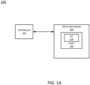
- the controller 102 may comprise a microcontroller or computing device, e.g., as illustrated in and described in greater detail with reference to FIG. 7 .
- the controller 102 may monitor the states of the drive mechanism 106 and of a consumable driven by the drive mechanism, and may send instructions to the drive mechanism 106 via electronic signals to facilitate locking and/or unlocking of the consumable.
- One example of a method for locking and unlocking a consumable is illustrated in and described in greater detail with reference to FIG. 5 .
- FIG. 1B is a high-level block diagram illustrating a more detailed depiction of the example system 100 of FIG. 1A .
- the system 100 may comprise a sub-system of a printing device.
- the system 100 generally comprises a controller 102, an output device 104, a drive mechanism 106, and a consumable 108.
- the controller 102, output device 104, and drive mechanism 106 may be permanent components of the printing device (i.e., where "permanent" does not imply that the components might not be subject to occasional replacement or repair), while the consumable 108 may be a component that is replaced with a similar component when it reaches at least a threshold level of depletion.
- the controller 102 may comprise a microcontroller or computing device, e.g., as illustrated in and described in greater detail with reference to FIG. 7 .
- the controller 102 may monitor the states of the output device 104, the drive mechanism 106, and/or the consumable 108 and send instructions to any of these components via electronic signals to facilitate locking and/or unlocking of the consumable 108.
- One example of a method for locking and unlocking a consumable such as the consumable 108 is illustrated in and described in greater detail with reference to FIG. 5 .
- the drive mechanism 106 comprises a device for driving the consumable 108.
- the drive mechanism 106 may engage the consumable 108, under instructions from the controller 102, to facilitate installation of the consumable 108 and extraction of a resource (e.g., toner, ink, detailing agent, or the like), when appropriate, from the consumable 108.
- the drive mechanism 106 may comprise a motor 110, a sensor 112, and a key 114.
- the motor 110 may move components of the drive mechanism 106, such as a delivery auger drive mechanism to which the key 114 is attached, to facilitate locking and/or unlocking of the consumable 108, as well as extraction of the resource from the consumable.
- the sensor 112 may detect the state of engagement between the drive mechanism 106 and the consumable 108 (e.g., partially engaged, fully engaged, etc.) and may send electronic signals to the controller 102 to notify the controller 102 of the state of engagement.
- the state of engagement between the drive mechanism 106 and the consumable 108 may be detected passively, e.g., without the use of the sensor 112.
- the key 114 may comprise a physical feature of the drive mechanism 106 (e.g., of a delivery auger drive mechanism of the drive mechanism 106) that allows the drive mechanism 106 to lock and unlock the consumable 108 in the printing device, under instructions from the controller 102. Examples of keys are illustrated in and described in greater detail with respect to FIGs. 2A-2D and 3A-3C .
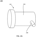
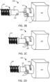
- FIGs. 2A-2D depict an example of a locking mechanism 200 for locking a consumable in a printing device.
- physical modifications are made to the delivery auger drive mechanism inside the printing device and to the mechanical drive coupling on the consumable that directly engages the delivery auger drive mechanism.
- the physical modifications allow the consumable to be locked in place when the mechanical drive coupling engages the delivery auger drive mechanism.
- the mechanical drive coupling 214 on the container 210 engages the shaft 204 of the delivery auger drive mechanism 202.
- the cartridge is inserted so that the pin 208 on the shaft 204 is positioned at a starting position of the ramp 218 on the mechanical drive coupling 214, as shown in FIG. 2C .
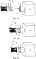
- FIGs. 3A-3C depict an example of a locking mechanism 300 for locking a consumable in a printing device.
- physical modifications are made to the delivery auger drive mechanism inside the printing device and to the mechanical drive coupling on the consumable that directly engages the delivery auger drive mechanism.
- the physical modifications allow the consumable to be locked in place when the mechanical drive coupling engages the delivery auger drive mechanism.
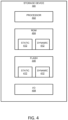
- the storage device 400 generally comprises a processor 402, at least one memory, e.g., a read only memory (ROM) 404 and a flash memory 406, and an I/O device 408.
- ROM read only memory
- the at least one memory may also include volatile memory as well.
- Either or both of the ROM 404 and the flash memory 406 may be used to store a plurality of values related to the consumable on which the storage device 400 is mounted. In one example, this plurality of values includes both a static value 410 and a dynamic value 412.
- the static value 410 comprises a value that relates to a security policy or contract attached to the consumable. For instance, the static value 410 may define a threshold level of depletion that the consumable should reach before it is unlocked, a range of times during which the consumable may be unlocked, or another value.
- the method 500 begins in block 502.
- the controller monitors the state of a consumable that is in use by the printing device.
- the controller may monitor the state of the consumable by extracting a dynamic value from a storage device (e.g., a read only memory and flash combination chip) that is mounted to the consumable.
- a storage device e.g., a read only memory and flash combination chip
- the controller detects that the consumable has been disengaged from the delivery auger drive mechanism.
- a sensor in the drive mechanism may send a signal to the controller indicating that the delivery auger drive mechanism is fully disengaged from the locking mechanism on the consumable.
- the controller may detect that a replacement consumable is attempting to engage the delivery auger drive mechanism.
- a sensor in the drive mechanism may send a signal to the controller indicating that the delivery auger drive mechanism has come into contact with the replacement consumable.
- method 500 proceeds to block 522.
- the controller sends an alert to the output device of the printing device (e.g., a display, a speaker, or the like) to notify the user to try again. For instance, the user may have failed to align the locking mechanism on the replacement consumable properly with the key of the delivery auger drive mechanism. Alternatively, the locking mechanism on the consumable may not be compatible with the key of the delivery auger drive mechanism (e.g., as may be the case when the user attempts to install the wrong type of toner cartridge). The method 500 then returns to block 516.
- method 500 proceeds to block 524.
- the controller sends a signal to the delivery auger drive mechanism to lock the replacement consumable in place, e.g., by fully engaging the locking mechanism on the replacement consumable (e.g., as illustrated in FIGs. 2D and 3C above). Once locked, the replacement consumable will not be able to be easily removed from the printing device unless it is unlocked by the controller (e.g., similar to the manner in which the depleted consumable was unlocked in block 512).
- the method 500 makes it more difficult for consumables to be replaced before they have reached some threshold level of depletion, thereby maximizing the usefulness of the consumable.
- the method 500 may also be used to prevent unauthorized replacement consumables from being installed in the printing device.
- a measure of confidence may be provided as to the consumable being replaced at the appropriate time. This will help refine the accuracy of the controller's operations with respect to consumables that are installed in the future. This may also help to detect problems with particular types (e.g., models) of consumables, for instance if a trend is detected in the data stored in the storage devices mounted on multiple consumables of the same type.
- the method 500 may also make it possible for user-(e.g., customer, CSP, or manufacturer) specific policies or security procedures to be defined and enforced.
- the controller could be programmed to enforce a consumable replacement policy that does not allow a consumable to be unlocked until it has reached at least a threshold level or depletion.
- the controller of Customer A's printing device may be configured to allow unlocking of a consumable when it reaches at least ninety percent depletion
- the controller of Customer B's printing device may be configured to allow unlocking of a consumable when it reaches one hundred percent depletion.
- FIG. 6 illustrates a flow diagram of an example method 600 for monitoring a state of a consumable in a printing device.
- the method 600 may be performed, for example, by the processor 402 configured as illustrated in FIG. 4 and/or by various other components of the storage device 400.
- the method 600 begins in block 602.
- a static value and a dynamic value stored in a memory (e.g., a ROM or a flash memory) of a storage device that is mounted on a consumable is transmitted to a controller of a printing device in which the consumable is installed.
- the static value relates to a security policy or contract attached to the consumable.
- the static value may define a threshold level of depletion that the consumable should reach before it is unlocked, a range of times during which the consumable may be unlocked, or another value.
- the dynamic value relates to a current state of the consumable.
- the dynamic value may define usage statistics for the consumable, such as the consumable's current level of depletion, the consumable's remaining life, the veracity of the consumable's origin, the number of times consumable has been inserted in a printing device, the number of pages printed using the consumable, level of depletion the last time the consumable was removed from a printing device (e.g., if the consumable is reusable), and/or other statistics.
- transmission of the static value and the dynamic value to the controller of the printing device involves transmitting the static value and the dynamic value over a set of contacts as an electrical current having a particular contact resistance.
- the dynamic value is overwritten in the memory of the storage device with a new dynamic value.
- the dynamic value is overwritten when a change is detected in the parameter or statistic that the dynamic value represents. For instance, if the dynamic value represents the consumable's current level of depletion, then the dynamic value may be overwritten each time the depletion level of the consumable is detected to reach some interval of depletion (e.g., every x percent depleted).
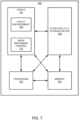
- FIG. 7 depicts a high-level block diagram of an example computer 700 that can be transformed into a machine capable of performing the functions described herein. Notably, no computer or machine currently exists that performs the functions as described herein. As a result, the examples of the present disclosure modify the operation and functioning of the general-purpose computer to lock a consumable in a printing device, as disclosed herein.
- the computer 700 comprises a hardware processor element 702, e.g., a central processing unit (CPU), a microprocessor, or a multi-core processor, a memory 704, e.g., random access memory (RAM) and/or read only memory (ROM), a module 705 for locking a consumable in a printing device, and various input/output devices 706, e.g., storage devices, including but not limited to, a tape drive, a floppy drive, a hard disk drive or a compact disk drive, a receiver, a transmitter, a speaker, a display, a speech synthesizer, an output port, an input port and a user input device, such as a keyboard, a keypad, a mouse, a microphone, and the like.
- a hardware processor element 702 e.g., a central processing unit (CPU), a microprocessor, or a multi-core processor
- the general-purpose computer may employ a plurality of processor elements.
- one general-purpose computer is shown in the figure, if the method(s) as discussed above is implemented in a distributed or parallel manner for a particular illustrative example, i.e., the blocks of the above method(s) or the entire method(s) are implemented across multiple or parallel general-purpose computers, then the general-purpose computer of this figure is intended to represent each of those multiple general-purpose computers.
- the present disclosure can be implemented by machine readable instructions and/or in a combination of machine readable instructions and hardware, e.g., using application specific integrated circuits (ASIC), a programmable logic array (PLA), including a field-programmable gate array (FPGA), or a state machine deployed on a hardware device, a general purpose computer or any other hardware equivalents, e.g., computer readable instructions pertaining to the method(s) discussed above can be used to configure a hardware processor to perform the blocks, functions and/or operations of the above disclosed methods.
- ASIC application specific integrated circuits
- PDA programmable logic array
- FPGA field-programmable gate array
- instructions and data for the present module or process 705 for locking a consumable in a printing device can be loaded into memory 704 and executed by hardware processor element 702 to implement the blocks, functions or operations as discussed above in connection with the method 500.
- the module 705 may include a plurality of programming code components, including a policy enforcement component 708 and a drive mechanism control component 710.
- the policy enforcement component 708 may be configured to enforce a user (e.g., customer, CSP, or manufacturer) policy regarding usage of consumables. For instance, the policy may dictate how much of a consumable should be depleted before the consumable can be replaced, the make or model of consumable that should be used in a printing device, or other consumable-related policies as discussed above.
- the policy enforcement component 708 may be in communication with a storage device on the consumable, or may monitor the state of the consumable in some other way in order to determine when actions should be taken to enforce a policy.
- the drive mechanism control component 710 may be configured to control an actuator (e.g., motor) that causes movement of a drive mechanism that engages a consumable. For instance, the drive mechanism control component 710 may control a motor that rotates the drive mechanism in a specific direction to lock or unlock a consumable, consistent with a policy enforced by the policy enforcement component 708.
- an actuator e.g., motor
- the drive mechanism control component 710 may control a motor that rotates the drive mechanism in a specific direction to lock or unlock a consumable, consistent with a policy enforced by the policy enforcement component 708.
- a hardware processor executes instructions to perform "operations"
- the processor executing the machine readable instructions relating to the above described method(s) can be perceived as a programmed processor or a specialized processor.
- the present module 705 for locking a consumable in a printing device, including associated data structures, of the present disclosure can be stored on a tangible or physical (broadly non-transitory) computer-readable storage device or medium, e.g., volatile memory, non-volatile memory, ROM memory, RAM memory, magnetic or optical drive, device or diskette and the like.
- the computer-readable storage device may comprise any physical devices that provide the ability to store information such as data and/or instructions to be accessed by a processor or a computing device such as a computer or an application server.
Landscapes
- Physics & Mathematics (AREA)
- General Physics & Mathematics (AREA)
- Engineering & Computer Science (AREA)
- Computer Vision & Pattern Recognition (AREA)
- Accessory Devices And Overall Control Thereof (AREA)
- Control Or Security For Electrophotography (AREA)
- Ink Jet (AREA)
- Pressure Vessels And Lids Thereof (AREA)
- Auxiliary Devices For And Details Of Packaging Control (AREA)
Claims (13)
- Einrichtung, die umfasst:einen Behälter (210, 310), um eine Menge einer Verbrauchsressource (108) zu fassen;eine Förderschnecke, die sich im Inneren des Behälters (210, 310) befindet;eine Öffnung (212, 312), die sich in dem Behälter (210, 310) befindet; undeine mechanische Antriebskupplung (214, 314), die an der Öffnung (212, 312) befestigt ist, wobei die mechanische Antriebskupplung (214, 314) umfasst:eine Bohrung (216, 316); undeinen Verriegelungsmechanismus (116, 200, 300) für eine Druckerkartusche, der in die Bohrung (216, 316) integriert ist, um den Behälter (210, 310) mit einem Antriebsmechanismus (106, 202, 302) zu verriegeln, wenn die Bohrung (216, 316) und der Antriebsmechanismus (106, 202, 302) drehbar in Eingriff stehen,wobei die Förderschnecke dazu konfiguriert ist, durch den Antriebsmechanismus (106, 202, 302) drehbar zu sein.
- Einrichtung nach Anspruch 1, wobei der Verriegelungsmechanismus (116, 200, 300) eine Rampe (218) umfasst, die in die Bohrung (216, 316) geschnitten ist.
- Einrichtung nach Anspruch 2, wobei die Rampe (218) einen spiralförmigen Pfad einschließlich einer Startposition und einer Endposition umfasst.
- Einrichtung nach Anspruch 1, wobei der Verriegelungsmechanismus (116, 200, 300) eine Vielzahl von Gewinden (318) umfasst, die im Inneren der Bohrung (216, 316) ausgebildet sind.
- Einrichtung nach Anspruch 1, die ferner umfasst:
eine computerlesbare Speicherungsvorrichtung (118, 400), die an dem Behälter (210, 310) angebracht ist. - Einrichtung nach Anspruch 5, wobei die computerlesbare Speicherungsvorrichtung (218, 400) umfasst:einen Speicher (404, 406), um einen statischen Wert (410) und einen dynamischen Wert (412) zu speichern;einen Prozessor (402), um den dynamischen Wert (412) zu überschreiben, wenn eine Änderung eines Parameters, der durch den dynamischen Wert (412) dargestellt wird, erkannt wird; undeine Eingabe-/Ausgabevorrichtung (408), um dem statischen Wert (410) und den dynamischen Wert (412) zu übertragen.
- Einrichtung nach Anspruch 6, wobei sich der statische Wert (410) auf eine Sicherheitsrichtlinie für die Einrichtung bezieht.
- Einrichtung nach Anspruch 6, wobei sich der Parameter, der durch den dynamischen Wert (412) dargestellt wird, auf einen Nutzungszustand der Einrichtung bezieht.
- Einrichtung nach Anspruch 8, wobei der Nutzungsstatus eine verbleibende Menge der Verbrauchsressource (108) in dem Behälter (210, 310) umfasst.
- Einrichtung nach Anspruch 6, wobei die Eingabe-/Ausgabevorrichtung (408) einen Satz elektrischer Kontakte umfasst.
- Einrichtung nach Anspruch 1, wobei die Einrichtung eine Tonerkartusche für eine Druckvorrichtung umfasst.
- Einrichtung nach Anspruch 1, wobei der Verriegelungsmechanismus (116, 200, 300) dazu dient, den Behälter (210, 310) bei einer anfänglichen Drehung des Antriebsmechanismus (106, 202, 302) in eine erste Richtung mit dem Antriebsmechanismus (106, 202, 302) zu verriegeln und bei einer nachfolgenden Drehung des Antriebsmechanismus (106, 202, 302) in die erste Richtung die Förderschnecke zu drehen.
- Einrichtung nach Anspruch 12, wobei der Verriegelungsmechanismus (116, 200, 300) dazu dient, den Behälter (210, 310) von dem Antriebsmechanismus (106, 202, 302) bei einer Drehung des Antriebsmechanismus (106, 202, 302) in eine zweite Richtung zu entriegeln, wobei die zweite Richtung der ersten Richtung entgegengesetzt ist.
Applications Claiming Priority (1)
| Application Number | Priority Date | Filing Date | Title |
|---|---|---|---|
| PCT/US2017/056511 WO2019074516A1 (en) | 2017-10-13 | 2017-10-13 | CONSUMABLES CONTAINING LOCKING MECHANISMS |
Publications (3)
| Publication Number | Publication Date |
|---|---|
| EP3638509A1 EP3638509A1 (de) | 2020-04-22 |
| EP3638509C0 EP3638509C0 (de) | 2025-01-22 |
| EP3638509B1 true EP3638509B1 (de) | 2025-01-22 |
Family
ID=60162335
Family Applications (1)
| Application Number | Title | Priority Date | Filing Date |
|---|---|---|---|
| EP17788085.3A Active EP3638509B1 (de) | 2017-10-13 | 2017-10-13 | Verbrauchsmaterialien mit verriegelungsmechanismen |
Country Status (6)
| Country | Link |
|---|---|
| US (1) | US10994549B2 (de) |
| EP (1) | EP3638509B1 (de) |
| CN (1) | CN110809520B (de) |
| ES (1) | ES3014631T3 (de) |
| PL (1) | PL3638509T3 (de) |
| WO (1) | WO2019074516A1 (de) |
Families Citing this family (5)
| Publication number | Priority date | Publication date | Assignee | Title |
|---|---|---|---|---|
| US10635368B2 (en) * | 2016-06-28 | 2020-04-28 | Hewlett-Packard Development Company, L.P. | Management of 3D printing |
| CN110392634B (zh) * | 2017-04-04 | 2022-06-07 | 惠普发展公司,有限责任合伙企业 | 耗材储存 |
| JP7593059B2 (ja) | 2020-10-30 | 2024-12-03 | 京セラドキュメントソリューションズ株式会社 | 画像形成装置、規制方法 |
| KR20230055827A (ko) | 2021-10-19 | 2023-04-26 | 휴렛-팩커드 디벨롭먼트 컴퍼니, 엘.피. | 소모품 유닛의 잠금 제어를 통한 crum 칩 오작동 방지 |
| WO2025018979A1 (en) * | 2023-07-14 | 2025-01-23 | Hewlett-Packard Development Company, L.P. | Audible or disconnectable indicator activated by trigger condition |
Citations (3)
| Publication number | Priority date | Publication date | Assignee | Title |
|---|---|---|---|---|
| JP2006168071A (ja) * | 2004-12-14 | 2006-06-29 | Canon Inc | インクタンク、記録ヘッドカートリッジおよびインクタンク装着方法 |
| US20080029085A1 (en) * | 2006-08-01 | 2008-02-07 | Greg Lawrence | Dispensing device |
| US20110121024A1 (en) * | 2008-07-26 | 2011-05-26 | Devos John A | Fluid supply contact |
Family Cites Families (6)
| Publication number | Priority date | Publication date | Assignee | Title |
|---|---|---|---|---|
| JP3086763B2 (ja) | 1993-03-09 | 2000-09-11 | 株式会社東芝 | 画像形成装置 |
| KR20060029881A (ko) | 2004-10-04 | 2006-04-07 | 삼성전자주식회사 | 카트리지 주문 관리방법 및 장치 |
| JP5120438B2 (ja) | 2010-10-25 | 2013-01-16 | 富士ゼロックス株式会社 | 着脱体及び画像形成装置 |
| JP2013041045A (ja) | 2011-08-12 | 2013-02-28 | Fuji Xerox Co Ltd | 画像形成装置 |
| US9067424B1 (en) * | 2014-01-09 | 2015-06-30 | Riso Kagaku Corporation | Ink cartridge and mount/demount mechanism for the same |
| US9317009B2 (en) | 2014-02-19 | 2016-04-19 | Xerox Corporation | Systems and methods for mounting an externally readable monitoring module on a rotating customer replaceable component in an operating device |
-
2017
- 2017-10-13 WO PCT/US2017/056511 patent/WO2019074516A1/en not_active Ceased
- 2017-10-13 CN CN201780092747.6A patent/CN110809520B/zh active Active
- 2017-10-13 ES ES17788085T patent/ES3014631T3/es active Active
- 2017-10-13 EP EP17788085.3A patent/EP3638509B1/de active Active
- 2017-10-13 PL PL17788085.3T patent/PL3638509T3/pl unknown
- 2017-10-13 US US16/640,983 patent/US10994549B2/en active Active
Patent Citations (3)
| Publication number | Priority date | Publication date | Assignee | Title |
|---|---|---|---|---|
| JP2006168071A (ja) * | 2004-12-14 | 2006-06-29 | Canon Inc | インクタンク、記録ヘッドカートリッジおよびインクタンク装着方法 |
| US20080029085A1 (en) * | 2006-08-01 | 2008-02-07 | Greg Lawrence | Dispensing device |
| US20110121024A1 (en) * | 2008-07-26 | 2011-05-26 | Devos John A | Fluid supply contact |
Also Published As
| Publication number | Publication date |
|---|---|
| CN110809520B (zh) | 2021-10-01 |
| EP3638509A1 (de) | 2020-04-22 |
| ES3014631T3 (en) | 2025-04-23 |
| PL3638509T3 (pl) | 2025-04-28 |
| US20200198357A1 (en) | 2020-06-25 |
| US10994549B2 (en) | 2021-05-04 |
| BR112020005727A2 (pt) | 2020-10-20 |
| EP3638509C0 (de) | 2025-01-22 |
| CN110809520A (zh) | 2020-02-18 |
| WO2019074516A1 (en) | 2019-04-18 |
Similar Documents
| Publication | Publication Date | Title |
|---|---|---|
| EP3638509B1 (de) | Verbrauchsmaterialien mit verriegelungsmechanismen | |
| US20170075277A1 (en) | Image forming apparatus, consumable product management method, and storage medium | |
| US9519449B2 (en) | Network printer system | |
| US9229363B2 (en) | Network printer system | |
| US11221809B2 (en) | Unlocking consumables | |
| CN101424908B (zh) | 色调剂盒 | |
| US20050271401A1 (en) | Systems and methods for remanufacturing imaging components | |
| EP2099089A1 (de) | Endgerät zur elektronischen Bezahlung, Konformitätsverfahren mindestens eines abnehmbaren Akkus eines solchen Endgeräts, entprechender abnehmbarer Akku und entsprechendes Computerprogrammprodukt | |
| EP3694723B1 (de) | Entriegelung von verbrauchsmitteln von druckvorrichtungen auf basis von vergleichen von aus speichervorrichtungen extrahierten werten | |
| US11110716B2 (en) | Locking consumables | |
| EP3077901B1 (de) | Netzwerkdruckersystem | |
| US20050034116A1 (en) | Control of programming electronic devices | |
| EP1195682A2 (de) | Einrichtung und Verfahren mit Zustandserkennung, Einrichtung die erkennt werden kann, und Druckergerät | |
| US7197633B2 (en) | Wireless machine post-launch configuration and option upgrade | |
| BR112020005727B1 (pt) | Aparelho compreendendo um mecanismo de bloqueio de recursos de insumos | |
| US7672105B2 (en) | Production of limited lifetime devices achieved through E-fuses | |
| WO2015088828A1 (en) | Network printer system | |
| EP1895755A1 (de) | Vorrichtung zur Bestimmung einer Modell-Leistung und Bildgebungsvorrichtung | |
| HK1153561A1 (en) | Consumer abuse detection system and method | |
| HK1153561B (en) | Consumer abuse detection system and method |
Legal Events
| Date | Code | Title | Description |
|---|---|---|---|
| STAA | Information on the status of an ep patent application or granted ep patent |
Free format text: STATUS: UNKNOWN |
|
| STAA | Information on the status of an ep patent application or granted ep patent |
Free format text: STATUS: THE INTERNATIONAL PUBLICATION HAS BEEN MADE |
|
| PUAI | Public reference made under article 153(3) epc to a published international application that has entered the european phase |
Free format text: ORIGINAL CODE: 0009012 |
|
| STAA | Information on the status of an ep patent application or granted ep patent |
Free format text: STATUS: REQUEST FOR EXAMINATION WAS MADE |
|
| 17P | Request for examination filed |
Effective date: 20200114 |
|
| AK | Designated contracting states |
Kind code of ref document: A1 Designated state(s): AL AT BE BG CH CY CZ DE DK EE ES FI FR GB GR HR HU IE IS IT LI LT LU LV MC MK MT NL NO PL PT RO RS SE SI SK SM TR |
|
| AX | Request for extension of the european patent |
Extension state: BA ME |
|
| DAV | Request for validation of the european patent (deleted) | ||
| DAX | Request for extension of the european patent (deleted) | ||
| STAA | Information on the status of an ep patent application or granted ep patent |
Free format text: STATUS: EXAMINATION IS IN PROGRESS |
|
| 17Q | First examination report despatched |
Effective date: 20220321 |
|
| GRAP | Despatch of communication of intention to grant a patent |
Free format text: ORIGINAL CODE: EPIDOSNIGR1 |
|
| STAA | Information on the status of an ep patent application or granted ep patent |
Free format text: STATUS: GRANT OF PATENT IS INTENDED |
|
| INTG | Intention to grant announced |
Effective date: 20240523 |
|
| GRAS | Grant fee paid |
Free format text: ORIGINAL CODE: EPIDOSNIGR3 |
|
| GRAA | (expected) grant |
Free format text: ORIGINAL CODE: 0009210 |
|
| STAA | Information on the status of an ep patent application or granted ep patent |
Free format text: STATUS: THE PATENT HAS BEEN GRANTED |
|
| AK | Designated contracting states |
Kind code of ref document: B1 Designated state(s): AL AT BE BG CH CY CZ DE DK EE ES FI FR GB GR HR HU IE IS IT LI LT LU LV MC MK MT NL NO PL PT RO RS SE SI SK SM TR |
|
| REG | Reference to a national code |
Ref country code: GB Ref legal event code: FG4D |
|
| REG | Reference to a national code |
Ref country code: CH Ref legal event code: EP |
|
| REG | Reference to a national code |
Ref country code: IE Ref legal event code: FG4D |
|
| REG | Reference to a national code |
Ref country code: DE Ref legal event code: R096 Ref document number: 602017087449 Country of ref document: DE |
|
| U01 | Request for unitary effect filed |
Effective date: 20250122 |
|
| U07 | Unitary effect registered |
Designated state(s): AT BE BG DE DK EE FI FR IT LT LU LV MT NL PT RO SE SI Effective date: 20250128 |
|
| RAP4 | Party data changed (patent owner data changed or rights of a patent transferred) |
Owner name: HEWLETT-PACKARD DEVELOPMENT COMPANY L.P. |
|
| U1H | Name or address of the proprietor changed after the registration of the unitary effect |
Owner name: HEWLETT-PACKARD DEVELOPMENT COMPANY L.P.; US |
|
| REG | Reference to a national code |
Ref country code: ES Ref legal event code: FG2A Ref document number: 3014631 Country of ref document: ES Kind code of ref document: T3 Effective date: 20250423 |
|
| PG25 | Lapsed in a contracting state [announced via postgrant information from national office to epo] |
Ref country code: RS Free format text: LAPSE BECAUSE OF FAILURE TO SUBMIT A TRANSLATION OF THE DESCRIPTION OR TO PAY THE FEE WITHIN THE PRESCRIBED TIME-LIMIT Effective date: 20250422 |
|
| PG25 | Lapsed in a contracting state [announced via postgrant information from national office to epo] |
Ref country code: IS Free format text: LAPSE BECAUSE OF FAILURE TO SUBMIT A TRANSLATION OF THE DESCRIPTION OR TO PAY THE FEE WITHIN THE PRESCRIBED TIME-LIMIT Effective date: 20250522 Ref country code: NO Free format text: LAPSE BECAUSE OF FAILURE TO SUBMIT A TRANSLATION OF THE DESCRIPTION OR TO PAY THE FEE WITHIN THE PRESCRIBED TIME-LIMIT Effective date: 20250422 |
|
| PG25 | Lapsed in a contracting state [announced via postgrant information from national office to epo] |
Ref country code: HR Free format text: LAPSE BECAUSE OF FAILURE TO SUBMIT A TRANSLATION OF THE DESCRIPTION OR TO PAY THE FEE WITHIN THE PRESCRIBED TIME-LIMIT Effective date: 20250122 |
|
| PG25 | Lapsed in a contracting state [announced via postgrant information from national office to epo] |
Ref country code: GR Free format text: LAPSE BECAUSE OF FAILURE TO SUBMIT A TRANSLATION OF THE DESCRIPTION OR TO PAY THE FEE WITHIN THE PRESCRIBED TIME-LIMIT Effective date: 20250423 |
|
| PG25 | Lapsed in a contracting state [announced via postgrant information from national office to epo] |
Ref country code: SM Free format text: LAPSE BECAUSE OF FAILURE TO SUBMIT A TRANSLATION OF THE DESCRIPTION OR TO PAY THE FEE WITHIN THE PRESCRIBED TIME-LIMIT Effective date: 20250122 |
|
| PGFP | Annual fee paid to national office [announced via postgrant information from national office to epo] |
Ref country code: PL Payment date: 20250924 Year of fee payment: 9 |
|
| PGFP | Annual fee paid to national office [announced via postgrant information from national office to epo] |
Ref country code: GB Payment date: 20250923 Year of fee payment: 9 |
|
| PG25 | Lapsed in a contracting state [announced via postgrant information from national office to epo] |
Ref country code: CZ Free format text: LAPSE BECAUSE OF FAILURE TO SUBMIT A TRANSLATION OF THE DESCRIPTION OR TO PAY THE FEE WITHIN THE PRESCRIBED TIME-LIMIT Effective date: 20250122 |
|
| PG25 | Lapsed in a contracting state [announced via postgrant information from national office to epo] |
Ref country code: SK Free format text: LAPSE BECAUSE OF FAILURE TO SUBMIT A TRANSLATION OF THE DESCRIPTION OR TO PAY THE FEE WITHIN THE PRESCRIBED TIME-LIMIT Effective date: 20250122 |
|
| U20 | Renewal fee for the european patent with unitary effect paid |
Year of fee payment: 9 Effective date: 20250923 |
|
| REG | Reference to a national code |
Ref country code: CH Ref legal event code: U11 Free format text: ST27 STATUS EVENT CODE: U-0-0-U10-U11 (AS PROVIDED BY THE NATIONAL OFFICE) Effective date: 20251101 |
|
| PLBE | No opposition filed within time limit |
Free format text: ORIGINAL CODE: 0009261 |
|
| STAA | Information on the status of an ep patent application or granted ep patent |
Free format text: STATUS: NO OPPOSITION FILED WITHIN TIME LIMIT |
|
| 26N | No opposition filed |
Effective date: 20251023 |
|
| PGFP | Annual fee paid to national office [announced via postgrant information from national office to epo] |
Ref country code: CH Payment date: 20251101 Year of fee payment: 9 |
|
| PGFP | Annual fee paid to national office [announced via postgrant information from national office to epo] |
Ref country code: ES Payment date: 20251103 Year of fee payment: 9 |