EP3638540B1 - Verschachtelte serielle netzwerkkonfiguration für eine anordnung aus seriell verbundenen scheinwerfern - Google Patents
Verschachtelte serielle netzwerkkonfiguration für eine anordnung aus seriell verbundenen scheinwerfern Download PDFInfo
- Publication number
- EP3638540B1 EP3638540B1 EP17913216.2A EP17913216A EP3638540B1 EP 3638540 B1 EP3638540 B1 EP 3638540B1 EP 17913216 A EP17913216 A EP 17913216A EP 3638540 B1 EP3638540 B1 EP 3638540B1
- Authority
- EP
- European Patent Office
- Prior art keywords
- light
- serial
- array
- serial data
- data bus
- Prior art date
- Legal status (The legal status is an assumption and is not a legal conclusion. Google has not performed a legal analysis and makes no representation as to the accuracy of the status listed.)
- Active
Links
Images



Classifications
-
- B—PERFORMING OPERATIONS; TRANSPORTING
- B60—VEHICLES IN GENERAL
- B60Q—ARRANGEMENT OF SIGNALLING OR LIGHTING DEVICES, THE MOUNTING OR SUPPORTING THEREOF OR CIRCUITS THEREFOR, FOR VEHICLES IN GENERAL
- B60Q1/00—Arrangement of optical signalling or lighting devices, the mounting or supporting thereof or circuits therefor
- B60Q1/0088—Details of electrical connections
- B60Q1/0094—Arrangement of electronic circuits separated from the light source, e.g. mounting of housings for starter circuits for discharge lamps
-
- H—ELECTRICITY
- H04—ELECTRIC COMMUNICATION TECHNIQUE
- H04L—TRANSMISSION OF DIGITAL INFORMATION, e.g. TELEGRAPHIC COMMUNICATION
- H04L12/00—Data switching networks
- H04L12/28—Data switching networks characterised by path configuration, e.g. LAN [Local Area Networks] or WAN [Wide Area Networks]
- H04L12/40—Bus networks
- H04L12/40169—Flexible bus arrangements
-
- B—PERFORMING OPERATIONS; TRANSPORTING
- B60—VEHICLES IN GENERAL
- B60Q—ARRANGEMENT OF SIGNALLING OR LIGHTING DEVICES, THE MOUNTING OR SUPPORTING THEREOF OR CIRCUITS THEREFOR, FOR VEHICLES IN GENERAL
- B60Q1/00—Arrangement of optical signalling or lighting devices, the mounting or supporting thereof or circuits therefor
- B60Q1/26—Arrangement of optical signalling or lighting devices, the mounting or supporting thereof or circuits therefor the devices being primarily intended to indicate the vehicle, or parts thereof, or to give signals, to other traffic
- B60Q1/2607—Arrangement of optical signalling or lighting devices, the mounting or supporting thereof or circuits therefor the devices being primarily intended to indicate the vehicle, or parts thereof, or to give signals, to other traffic comprising at least two indicating lamps
-
- B—PERFORMING OPERATIONS; TRANSPORTING
- B60—VEHICLES IN GENERAL
- B60Q—ARRANGEMENT OF SIGNALLING OR LIGHTING DEVICES, THE MOUNTING OR SUPPORTING THEREOF OR CIRCUITS THEREFOR, FOR VEHICLES IN GENERAL
- B60Q1/00—Arrangement of optical signalling or lighting devices, the mounting or supporting thereof or circuits therefor
- B60Q1/26—Arrangement of optical signalling or lighting devices, the mounting or supporting thereof or circuits therefor the devices being primarily intended to indicate the vehicle, or parts thereof, or to give signals, to other traffic
- B60Q1/2611—Indicating devices mounted on the roof of the vehicle
-
- H—ELECTRICITY
- H04—ELECTRIC COMMUNICATION TECHNIQUE
- H04L—TRANSMISSION OF DIGITAL INFORMATION, e.g. TELEGRAPHIC COMMUNICATION
- H04L12/00—Data switching networks
- H04L12/28—Data switching networks characterised by path configuration, e.g. LAN [Local Area Networks] or WAN [Wide Area Networks]
- H04L12/40—Bus networks
- H04L12/407—Bus networks with decentralised control
- H04L12/417—Bus networks with decentralised control with deterministic access, e.g. token passing
-
- H—ELECTRICITY
- H04—ELECTRIC COMMUNICATION TECHNIQUE
- H04L—TRANSMISSION OF DIGITAL INFORMATION, e.g. TELEGRAPHIC COMMUNICATION
- H04L12/00—Data switching networks
- H04L12/28—Data switching networks characterised by path configuration, e.g. LAN [Local Area Networks] or WAN [Wide Area Networks]
- H04L12/46—Interconnection of networks
- H04L12/4604—LAN interconnection over a backbone network, e.g. Internet, Frame Relay
- H04L12/462—LAN interconnection over a bridge based backbone
- H04L12/4625—Single bridge functionality, e.g. connection of two networks over a single bridge
-
- H—ELECTRICITY
- H04—ELECTRIC COMMUNICATION TECHNIQUE
- H04L—TRANSMISSION OF DIGITAL INFORMATION, e.g. TELEGRAPHIC COMMUNICATION
- H04L12/00—Data switching networks
- H04L12/28—Data switching networks characterised by path configuration, e.g. LAN [Local Area Networks] or WAN [Wide Area Networks]
- H04L12/40—Bus networks
- H04L2012/40208—Bus networks characterized by the use of a particular bus standard
- H04L2012/40215—Controller Area Network CAN
-
- H—ELECTRICITY
- H04—ELECTRIC COMMUNICATION TECHNIQUE
- H04L—TRANSMISSION OF DIGITAL INFORMATION, e.g. TELEGRAPHIC COMMUNICATION
- H04L12/00—Data switching networks
- H04L12/28—Data switching networks characterised by path configuration, e.g. LAN [Local Area Networks] or WAN [Wide Area Networks]
- H04L12/40—Bus networks
- H04L2012/40267—Bus for use in transportation systems
- H04L2012/40273—Bus for use in transportation systems the transportation system being a vehicle
Definitions
- This disclosure relates to an improved serial bus architecture for a vehiclemountable array (e.g., a light bar) of serially connected light modules, also called light engines and-according to the Society of Automotive Engineers (SAE)-light heads such as those of the class-one type of directional flashing optical warning devices for authorized emergency, maintenance, and service vehicles.
- SAE Society of Automotive Engineers
- this disclosure relates to a light bar having intrinsic- and extrinsic-facing serial data bus interfaces by which to convey messages controlling an internal group of serially connected light heads integral to the array.
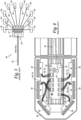
- FIGS. 1 and 2 show examples of previous attempts at light bar wiring technologies 10 that include bulky, multi-conductor wiring harnesses 12 for carrying illumination-control signals from a set of discrete inputs 16 to each corresponding light head 20 in a light bar 26 ( FIG. 2 ).
- Each light head 20 has at least one separate wire connection 30 that is assembled based on a predetermined wire-color combination. Additional wires 34 ( FIG. 2 ) to each light head 20 may provide different illumination-control signals, some of which are applicable to only a subset of light heads or a subset of lighting components available within a light head.
- multicolor-emitting modules typically expect several dedicated wires for each light-emitting diode (LED) color present in a light head.
- LED light-emitting diode
- the wiring scheme becomes inherently complicated, as shown in FIG. 2 .
- the numerous wires and light heads in light bar 26 tend to increase the likelihood of various installation errors. Mismatched wire colors and location-installation errors, e.g., due to assembly errors, compromise product functionality.
- the complex wiring scheme results in increased assembly and test time, both of which increase production and support costs attributable to previous light bar wiring technologies 10. Given the sheer number of LED module types and combinations, electronic quality control is fraught with practical challenges.
- serial bus technologies 40 of FIGS. 3 and 4 which are limited to an external-facing serial bus interface 42 provided as a substitute for discrete inputs 16 (described previously).
- a serial bus 44 facilitates communication of serial data received at a light bar 46 ( FIG. 4 ).
- the data are then converted by an integrated circuit (IC) 50 (e.g., a microcontroller) into signals carried by discrete wires 30 to light heads 20, as described previously.
- IC integrated circuit
- Serial bus technologies 40 therefore, rely on circuitry 50 to interpret serial messages and convert them into illumination-control signals carried through discrete wires 30 housed inside light bar 46.
- FIG. 5 shows an example implementation of the high-speed specification that describes linear CAN bus 54 including three CAN nodes 62 connected to one another through two wires 82 terminated at each end with 120 ohm ( ⁇ ) resistors 84. Wires 82 are 120 ⁇ nominal twisted pair, according to one embodiment.
- CAN affords support for a limited number of nodes due to several physical constraints.
- One constraint for example, is based on the loop time during an arbitration procedure in which a signal (sent by a transmitter node) is transmitted across the bus to a farthest receiver node and back again to the transmitter node. This propagation delay is dependent on the number of nodes and their delay-causing capacitances, the type of cabling employed in the bus, and other physical aspects. Though it is possible to increase the number of nodes by decreasing a data rate of the bus, or by employing transceivers having small input capacitance, these workaround attempts are not feasible in some environments having numerous nodes, such as the environment shown and described with reference to FIG. 6 .
- a CAN node typically includes a CAN controller and a CAN transceiver.
- the CAN controller includes, for example, embedded logic implementing the CAN protocol.
- the CAN transceiver provides a circuitry interface to the physical CAN bus. These two components are frequently packaged together in a common IC platform, such as in a microcontroller. Accordingly, skilled persons will appreciate that a complete CAN solution may be referred to generally as CAN node circuitry or simply as a CAN controller.
- the underlying physical wiring employed in ECCONet includes a variety of wiring options such as, for example, two-pin data wires 110 between a signal distribution node 112 and a serial-interface board (SIB) 118; a data cable 122 (see also, FIG. 8 ) connection between SIB 118 and three array controllers (ACs) 130, 136, 140 having 8 position, 8 contact (8P8C) plug connectors 146 ( FIG.
- SIB serial-interface board
- ACs array controllers
- RJ45 modular connectors in the context of Ethernet-type cables
- SIB 118 is a dedicated controller node having a personal computer (PC) interface that, as explained later with reference to FIG. 9 , enables an end user to readily reconfigure their system. SIB 118 also includes dedicated memory space by which to maintain network-level status logs. SIB 118 communicatively couples several different ECCONet nodes that employ the aforementioned different cable connections while also providing optional auxiliary features, such as an interface for discrete I/O or a siren.
- PC personal computer
- ECCONet operates without an SIB, at the discretion of the end user weighing cost, complexity, and desired functionality.
- any combination of two or more ECCONet nodes could form an autonomous system. This is so because priority functions and system synchronization are accomplished via the CAN message structure of the bus itself.
- CAN differs from other common embedded networks in that it operates with a multi-master structure. There is no host controller per se, such as in a Universal Serial Bus (USB), and no master-slave relationship per se, such as in a Serial Peripheral Interface (SPI) bus.
- USB Universal Serial Bus
- SPI Serial Peripheral Interface
- Any CAN nodes communicatively coupled through bus 108 may be provided by a different original equipment manufacturer (OEM). And the complexity of a CAN node can range from a simple I/O device to a complex embedded computer having an integrated CAN controller and relatively sophisticated software.
- a node may also be a gateway allowing a standard computer (see e.g., FIG. 9 ) to communicate over a USB or Ethernet port to the devices on a CAN network. Accordingly, bus 108 facilitates interoperability between products independently developed by OEMs and partners.
- a rooftop array 166 of light heads 170 appears to other nodes on bus 108 as a unitary CAN node that receives and transmits serial data through bus 108. Rather than convert that data to discrete I/O (e.g., power cycling) for each light head 170, each light head 170 within light bar 174 is itself a node on a secondary (nested) CAN serial data bus 180 maintained in serial communication by array controller 136 of light bar 174.
- Vehicle 100 and bus 108 also accommodate other types of arrays in lieu of or in addition to rooftop array 166.
- FIG. 6 shows several such arrays, although in practice most emergency vehicles will either have one rooftop array, front- and rear-facing arrays (e.g., for so-called slick-top vehicles), or some combination of rooftop and front- and rear-facing arrays.
- a rear-facing rooftop external array 184 (known as a Safety Director TM configuration) includes array controller 140 and multiple light heads 186 communicatively coupled to another nested CAN bus 190.
- a lower front windshield interior array 194 includes array controller 130 and multiple light heads 196 communicatively coupled to another nested CAN bus 200.
- Additional slick-top embodiments (not shown) of arrays having a nested CAN bus available from Code 3, Inc. include an upper front windshield interior array arranged according to a Supervisor ® configuration; a lower rear window interior array arranged according to a WingMan TM configuration; and an upper rear window exterior array mountable to a fiberglass visor, which is also called roof spoiler arranged according to a Citadel TM configuration for sport-utility vehicles.
- a single array controller maintains multiple spaced-apart arrays.
- the maximum baud rate of a low speed CAN bus is 125 kilobit per second (symbol kbit/s or kb/s, often abbreviated "kbps"), which is the standard rate for ECCONet nodes.
- cable 122 and associated connectors 146 implement a robust line topology, per ISO 11898-2, which is less subject to electromagnetic interference (EMI) and supports communication speeds up to one megabit per second (Mbit/s or Mb/s, often abbreviated "Mbps").
- EMI electromagnetic interference
- Mbit/s or Mb/s often abbreviated "Mbps”
- systems including SIB 118 will conform to the line topology of a high speed CAN bus of FIG. 5 , irrespective of the communication baud rate.
- ECCONet includes a higher-speed ISO 11898-2 CAN bus.
- array controller 220 when array controller 220 receives an instruction to initiate the flash pattern as a sequence of light emitted by different ones of light modules 236, it maintains the flash pattern sequence timing by generating a series of synchronized messages communicated through second controller 250 over bus 238. During an active pattern of flashes, a dim level may be updated on the fly at any time by separate messages delivered to light modules 236.
- the synchronized messages are broadcast messages addressed to every CAN-identifier present on bus 238. This is made possible by, for example, each light module 236 having internal flash pattern instructions that indicate whether the associated light module should flash or skip a particular broadcast message in the sequence.
- the synchronized messages are addressed to individual or subsets of CAN-identifiers.
- broadcast messages include data fields having instructions, such as a bitmask, that encode whether a given light module should flash once the instructions are processed by a light head microcontroller.
- microcontroller 240 is a member of the Programmable System-on-Chip (PSoC ® ) 4200-L product family of programmable embedded system controllers available from Cypress Semiconductor Corporation of San Jose, California.
- the PSoC ® 4200-L product family is based on a scalable and reconfigurable platform architecture including an ARM@ Cortex ® -M0 central processing unit (CPU).
- the product family is characterized by its combination of microcontroller with digital programmable logic, and including programmable analog, programmable interconnect, secure expansion of memory off-chip, analog-to-digital converters (ADCs), operational amplifiers with a comparator mode, and standard communication and timing peripherals.
- ADCs analog-to-digital converters
- the bridge implemented through internal logic of the microcontroller, provides a path by which to translate CAN communications from nodes of one bus to those the other. It also facilitates firmware updates or configuration changes initiated from the ECCONet side, as explained later with reference to FIG. 9 .
- Each light head 236 also includes controller circuitry for establishing a node on bus 238.
- each light head 236 includes an ATmega16M1 automotive 8-bit AVR ® microcontroller available from Atmel Corporation of San Jose, California. This type of microcontroller includes, among other things, 16 kilobytes of in-system memory; internal CAN node circuitry (e.g., a CAN 2.0A/B controller); a 10-bit ADC having up to 11 single ended channels; and an on-chip temperature sensor for communicating temperature information through a secondary CAN serial data bus 238 to array controller 220, which reports this diagnostic information through bus 224 to other nodes (e.g., keypad 154 or SIB 118, FIG. 6 ) facilitating audible or visual presentation of an over-temperature condition occurring at an individual light head.
- nodes e.g., keypad 154 or SIB 118, FIG. 6
- FIG. 8 shows a fully integrated embodiment of a serial light bar 256 having a streamlined and simplified internal wiring configuration that readily scales irrespective of the number of light heads or colors available on each light module. Wiring orientation also becomes irrelevant, so long as all heads are connected in a serial chain. There are no wire colors or harnesses to match up with specific light locations.
- computer device 288 facilitates automatic or user-initiated testing and configuration of light head capabilities on the internal, nested CAN bus.
- the testing and configuration may check or facilitate any of the following capabilities: temperature sensing, dimming features, color verification, spatial arrangement confirmation, identification of failed heads, calculation of max instantaneous current draw for an entire array (e.g., while testing under the most power-intensive flash patterns), and development of desired flash patterns.
- a user initially selects from GUI 292 a light bar model matching that of light bar 174.
- Another message may be sent to update the now-confirmed light head 306 (or to update array controller 136) with a corresponding position identifier.
- the user also confirms light head 306 emits the appropriate colors of light by comparing the emitted colors to those shown by GUI 292.
- a self-identification (self-ID) process is performed by light heads on the secondary bus so as to verify that an installed module is the one that possesses the desired specifications for a particular array, e.g., it produces the correct color and has the correct number of LEDs.
- the self-ID process ensures the desired configuration of the array and may be performed prior to any other user-initiated testing of light heads present on a secondary bus.
- Skilled persons will appreciate, however, that light heads present on the primary (ECCONet) bus may also implement the self-ID techniques or other diagnostic capabilities described in this disclosure, according to some embodiments. When implemented on the primary bus, the light heads coupled thereto would provide color information, temperature, and other diagnostic information communicated over the primary bus.
- a value for a PORT ID is established by a combination of two half bytes: CLASS, which is a hardcoded value, and an ADC channel number, which is dynamically determined based on a number of an ADC channel, e.g. ADC0 318 ( FIG. 10 ), assigned to a first control line (L0) 320 that actuates a middle string of LEDs 326.
- CLASS which is a hardcoded value
- ADC channel number which is dynamically determined based on a number of an ADC channel, e.g. ADC0 318 ( FIG. 10 ), assigned to a first control line (L0) 320 that actuates a middle string of LEDs 326.
- the CLASS half-byte is hardcoded in firmware based on the light head family. Note that all assembly variants of the same family have the same firmware version and hardware platform. Thus, the assembly variants sharing a common hardware platform also share a common class number for the family. The use of unique classes for different hardware platforms expands the number of serial light head combinations available for design variants. Class number zero (binary number 0000) is declared invalid so as to avoid a valid PORT ID having all eight of its bits equal to zero.
- the information of Table 1 (or a portion thereof) is available at computer device 288 or array controller 136, which resolves the light head family based on the received PORT ID value. If the light head family does not match the family that is desired for array 170, or any other installation error is detected, then an error notification or visual alert is provided to a user of GUI 292.
- LED configurations e.g., a six-string red/blue configuration
- other configurations are appropriate for service vehicles (e.g., a two-string amber/white configuration).
- the same unpopulated (bare) PCB may support these different strings of LEDs that are not reported via the PORT ID. Therefore, to dynamically differentiate LED configurations within a family, the value of the COLOR ID represents all valid raw ADC values observed for a light head, since these values-in cooperation with the MASK explained later-differentiate the LED configuration.
- each unpopulated (bare) PCB has certain members of a predetermined set of ADC channel numbers that are electrically connected to LEDs that activate in response to corresponding control lines.
- a light head activates one of the control lines, polls each of its designated ADC inputs one at a time, detects input voltages, updates the COLOR ID as explained below, tests the next control line, and so forth.
- Some light heads may use up to six control lines and up to eight ADC inputs (e.g. a control line actuates multiple strings but ADC inputs check strings individually), but the firmware optionally establishes that only specific inputs are to be checked. As shown in Table 2, for each ADC channel detecting a relatively high voltage between about 0.8 V and about 1.33 V, the light head will insert a binary '1' in the corresponding COLOR ID bit location.
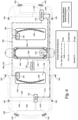
- FIG. 10 shows that a 9UP light head of the Torus 3UP/6UP/9UP family includes (white) string 326 of three white LEDs 340, a first red string 350 of three red LEDs 356, and a second red string 360 of three red LEDs 366.
- the three strings 326, 350, and 360 activate in response to signals applied to, respectively, control lines L0 320, L1 370, and L2 380.
- ADC0 318 which corresponds to first control line L0 320, detects a relatively high voltage across white LEDs 340.
- ADC3 386 and ADC5 344 detect relatively low voltage drops because red LEDs 356 and 366 have a different forward voltage drop than that of white LEDs 340.
- the COLOR ID of Table 2 shows a high voltage drop is encoded as a '1' in the LSB location representing ADC0 318 and the low voltage drops are encoded as '0' in each of the third and fourth bit locations representing, respectively, ADC3 386 and ADC5 344.
- a 9UP member of the family has red, white, and amber strings that activate in response signals on, respectively, control lines L1, L0 and L2.
- the COLOR ID for this example is shown in Table 3.
- a middle string of white LEDs on L0 are encoded as a '1' for ADC0; an upper string of red LEDs on L1 are encoded as a '0' for ADC3; and a lower string of amber LEDs on L2 are encoded as a '1' for ADC5.
- Table 3 COLOR ID, 9UP red/white/amber (Torus 3UP/6UP/9UP family) COLOR ID: 0000 1001 ADC9 ADC8 ADC7 ADC6 ADC5 ADC3 ADC2 ADC0 0 0 0 0 1 0 0 1
- an 8UP member of a different family has two amber strings that activate in response signals on, respectively, control lines L0 and L1. Unlike in the previous examples, however, these control lines correspond to, respectively, ADC8 and ADC9. Other combinations are possible as well.
- Table 4 shows several ranges and their associated status conditions. Table 4: Example Raw ADC Ranges and Associated Status Sampled Raw* ADC value (V) Status about 0 String populated but not active, or open circuit. 0.2-0.45 String damaged, unknown error. 0.5-1.33 String populated, active.
- lower voltage corresponds to red LEDs and some types of amber LEDs (R/A); higher voltage (0.81-1.33 V) corresponds to blue, green, white (B/G/W) and other types of amber LEDs. >1.33 String shorted. *Raw ADC value is about one third of the actual value of the voltage.
- the MASK has six bits (called ID bits) established by external pull-down resistors, or other techniques, that provide digital voltage ranges sampled by digital I/O inputs of a light head microcontroller. Accordingly, a microcontroller samples voltages at defined I/O pins to determine the value of the six corresponding bits.
- a high digital logic level is encoded as a binary '1,' and vice versa. The two most significant bits of the MASK are reserved for future use.
- a high bit is established by an unplaced (void) resistor on a bare PCB.
- ID0 and ID1 identify a single-, double-, or tri-color head.
- a tri-color head has '11' for ID0 and ID1.
- ID2-ID5 represent additional bits that further distinguish different types of light heads among a family.
- a table or other data structure for the particular family maps the MASK and COLOR ID to a particular light head and LED configuration within the family. For example, upon request, a light head will transmit its PORT ID, COLOR ID, and MASK to, e.g., computer device 288.
- Computer device 288 contains its own version of a PORT ID table to identify the light head family (bare PCB type). Once computer device 288 has identified the light head family (bare PCB type), it then uses the COLOR ID and MASK to pinpoint the light head type from a table (or other data structure), such as the example shown in Table 5.
- Table 5 MASK and COLOR ID, Individualized Light Head LED Configuration Matrix Torus 3UP/6UP/9UP family)
- MASK COLOR ID ID0-ID1 ID2-ID5 ADC5, ADC3, ADC0: 1 Raw ADC between 0.5-1.33
- V 0 Raw ADC between 0.2-0.45
- V X Raw ADC between 0.0-0.2
- V Y Raw ADC (Do Not Care) Y,Y,1 0,Y,1 ... 1, 0, 1 01 (single) 1111 3UP white ... ... 10 (double) 1111 ... ... 11 (triple) 1111 9UP red/white/red (Table 2) 9UP red/white/amber (Table 3)
- GUI 292 may store and present a subset of known or desired combinations, rather than a very large table including placeholders for all possible combinations.
Landscapes
- Engineering & Computer Science (AREA)
- Mechanical Engineering (AREA)
- Computer Networks & Wireless Communication (AREA)
- Signal Processing (AREA)
- Circuit Arrangement For Electric Light Sources In General (AREA)
Claims (6)
- Eine optische Warnungsvorrichtung, die eine Anordnung (166) von mehreren Lichtmodulen (236) für ein Fahrzeug (100) beinhaltet, aufweisend einen primären seriellen Datenbus (108, 204) eines Controller Area Networks, CAN, um erste serielle Kommunikationen unter beabstandeten CAN-Knoten (112, 118, 130, 136, 140, 154, 220, 260, 288) auszutragen, die kommunikativ damit gekoppelt sind, wobei die ersten seriellen Kommunikationen zum Initiieren einer Lichtblitzsequenz von der Anordnung dienen, die Folgendes beinhaltet:einen sekundären seriellen CAN-Datenbus (238) zum Aufbauen eines verschachtelten seriellen CAN-Datenbusses (180, 190, 200, 238), der als Antwort auf die ersten seriellen Kommunikationen zweite serielle Kommunikationen austrägt, die den mehreren Lichtmodulen bereitgestellt werden, die kommunikativ damit gekoppelt sind, wobei die zweiten seriellen Kommunikationen zum Steuern der Lichtblitzsequenz von der Anordnung dienen;wobei jedes der mehreren Lichtmodule Lichtmodul-CAN-Knotenschaltungen umfasst,wobei die Lichtmodul-CAN-Knotenschaltungen eine Lichtmodul-CAN-Steuereinheit umfassen, die mit dem sekundären seriellen CAN-Datenbus elektrisch gekoppelt ist, sodass eine Impedanz der Lichtmodul-CAN-Knotenschaltungen von dem primären seriellen CAN-Datenbus elektrisch isoliert ist, wenn ein assoziiertes Lichtmodul in dem Fahrzeug operativ eingesetzt ist; undeine Anordnungssteuereinheit (130, 136, 140, 220, 260), die erste und zweite CAN-Knotenschaltungen umfasst, die konfiguriert sind, um den primären und sekundären seriellen CAN-Datenbus kommunikativ zu trennen und zu überbrücken, wobei die ersten CAN-Knotenschaltungen eine erste CAN-Steuereinheit umfassen, die mit dem primären seriellen CAN-Datenbus elektrisch koppelbar ist, um einen ersten CAN-Knoten zum Erleichtern der ersten seriellen Kommunikationen aufzubauen, und die zweiten CAN-Knotenschaltungen eine zweite CAN-Steuereinheit umfassen, die mit dem sekundären seriellen CAN-Datenbus elektrisch gekoppelt ist, um einen zweiten CAN-Knoten zum Erleichtern der zweiten seriellen Kommunikationen aufzubauen, wobei die Anordnung Folgendes ist:a) ein Lichtbalken, der auf einem Dach des Fahrzeugs montierbar ist;b) ein Safety Director, der auf dem Fahrzeug montierbar ist und angeordnet ist, um ein nach hinten weisendes Lichtblitzmuster bereitzustellen;c) an einem hinteren Flügel des Fahrzeugs montierbar ist;d) eine an der Heckscheibe montierbare Anordnung, die angeordnet ist, um ein nach hinten weisendes Lichtblitzmuster bereitzustellen; odere) eine an der Windschutzscheibe montierbare Anordnung, die proximal zu einem Flügel angeordnet ist, um ein nach vorne weisendes Lichtblitzmuster bereitzustellen.
- Optische Warnungsvorrichtung gemäß Anspruch 1, wobei der sekundäre serielle CAN-Datenbus serielle Datenverkabelung umfasst, die die mehreren Lichtmodule verbindet, und wobei der Lichtbalken die serielle Datenverkabelung des sekundären seriellen CAN-Datenbusses beherbergt.
- Optische Warnungsvorrichtung gemäß Anspruch 1, die ferner Folgendes beinhaltet:
ein computerlesbares Medium, das Anweisungen umfasst, die darauf gespeichert sind, die, wenn sie von einem Microcontroller des Anordnungscontrollers ausgeführt werden, den Anordnungscontroller zu Folgendem konfigurieren:als Antwort auf das Empfangen eines ersten seriellen Befehls durch den primären seriellen CAN-Datenbus, Verarbeiten des ersten seriellen Befehls, um eine Sequenz von zweiten seriellen Befehlen für die mehreren Lichtmodule zu bestimmen; undals Antwort auf das Bestimmen der Sequenz von zweiten seriellen Befehlen, Erzeugen der zweiten seriellen Kommunikationen gemäß der Sequenz, um die Lichtblitzsequenz basierend auf dem ersten seriellen Befehl zu steuern. - Optische Warnungsvorrichtung gemäß Anspruch 1, die ferner mehrere Temperaturfühler beinhaltet, wobei jedes der mehreren Lichtmodule einen anderen der mehreren Temperaturfühler zum Übermitteln von Temperaturinformationen durch den sekundären seriellen CAN-Datenbus umfasst.
- Optische Warnungsvorrichtung gemäß Anspruch 1, wobei jedes der mehreren Lichtmodule mehrere Analog-Digital-Wandler(ADC)-Kanäle umfasst, die mit entsprechenden Strängen von Leuchtdioden (LEDs) elektrisch gekoppelt sind, wobei die ADC-Kanäle konfiguriert sind, um Spannungen zu messen, die mit den entsprechenden Strängen von LEDs assoziiert sind, sodass ein assoziiertes Lichtmodul konfiguriert ist, um durch den sekundären seriellen CAN-Datenbus eine digitale Darstellung der gemessenen Spannungen zu übermitteln, wobei die digitale Darstellung einer vordefinierten Hardwareplattform des assoziierten Lichtmoduls entspricht.
- Optische Warnungsvorrichtung gemäß Anspruch 1, wobei die Anordnungssteuereinheit eines von Folgenden beinhaltet:eine integrierte Schaltung des Microcontrollers, die die ersten und zweiten CAN-Knotenschaltungen einschließt;einen ersten und einen zweiten Microcontroller, die kommunikativ miteinander gekoppelt sind, wobei der erste Microcontroller die ersten CAN-Knotenschaltungen umfasst und der zweite Microcontroller die zweiten CAN-Knotenschaltungen umfasst.
Applications Claiming Priority (1)
| Application Number | Priority Date | Filing Date | Title |
|---|---|---|---|
| PCT/US2017/037506 WO2018231225A1 (en) | 2017-06-14 | 2017-06-14 | Nested serial network configuration for array of serially connected light heads |
Publications (3)
| Publication Number | Publication Date |
|---|---|
| EP3638540A1 EP3638540A1 (de) | 2020-04-22 |
| EP3638540A4 EP3638540A4 (de) | 2021-05-12 |
| EP3638540B1 true EP3638540B1 (de) | 2023-12-27 |
Family
ID=64660855
Family Applications (1)
| Application Number | Title | Priority Date | Filing Date |
|---|---|---|---|
| EP17913216.2A Active EP3638540B1 (de) | 2017-06-14 | 2017-06-14 | Verschachtelte serielle netzwerkkonfiguration für eine anordnung aus seriell verbundenen scheinwerfern |
Country Status (4)
| Country | Link |
|---|---|
| US (1) | US10773634B2 (de) |
| EP (1) | EP3638540B1 (de) |
| AU (1) | AU2017418296B2 (de) |
| WO (1) | WO2018231225A1 (de) |
Families Citing this family (9)
| Publication number | Priority date | Publication date | Assignee | Title |
|---|---|---|---|---|
| US12143239B2 (en) | 2018-07-19 | 2024-11-12 | Electronic Controls Company | Control of vehicle-carried warning system through controller area network (CAN) communications of global variables processed as operands of behavioral equations |
| JP7124618B2 (ja) * | 2018-10-03 | 2022-08-24 | 株式会社オートネットワーク技術研究所 | 自動車用配線システム |
| ES2998204T3 (en) * | 2019-03-13 | 2025-02-19 | Whelen Eng | System and method for controlling multiple serial control devices in an emergency vehicle |
| FR3097938B1 (fr) * | 2019-06-25 | 2021-09-10 | Vignal Systems | Dispositif de signalisation lumineuse modulaire pour un véhicule |
| EP4501706A3 (de) | 2020-01-09 | 2025-06-04 | Electronic Controls Company | Flexible richtungsabhängige warnleuchte für fahrzeuge |
| DE102021124170B4 (de) | 2021-09-19 | 2024-12-19 | Elmos Semiconductor Se | Beleuchtungsvorrichtung mit nur einem CAN-Datenbusanschluss und mehreren CAN-Busknoten ohne internen CAN-Datenbus |
| US11958403B2 (en) | 2022-05-23 | 2024-04-16 | Caterpillar Inc. | Rooftop structure for semi-autonomous CTL |
| US20240343215A1 (en) * | 2023-04-12 | 2024-10-17 | Oshkosh Corporation | Light system for response vehicle |
| US12227121B1 (en) * | 2023-11-01 | 2025-02-18 | Xin Dong | Harness for emergency vehicle lights |
Family Cites Families (20)
| Publication number | Priority date | Publication date | Assignee | Title |
|---|---|---|---|---|
| DE4129205A1 (de) | 1991-03-28 | 1992-10-01 | Bosch Gmbh Robert | Verfahren zum aufbau von botschaften fuer den datenaustausch und/oder fuer die synchronisation von prozessen in datenverarbeitungsanlagen |
| US5884997A (en) * | 1996-10-25 | 1999-03-23 | Federal Signal Corporation | Light bar |
| US6751695B1 (en) * | 1999-03-02 | 2004-06-15 | Koninklijke Philips Electronics N.V. | Bus bridge device for advanced microcontroller bus architecture (AMBA) advanced system bus (ASB) protocol |
| US20050047167A1 (en) * | 1999-08-04 | 2005-03-03 | Pederson John C. | Warning signal light bar |
| DE102005053103B4 (de) * | 2005-11-04 | 2008-04-24 | Phoenix Contact Gmbh & Co. Kg | Verfahren sowie System zur Übertragung von zyklischen und azyklischen Daten |
| US9346397B2 (en) * | 2006-02-22 | 2016-05-24 | Federal Signal Corporation | Self-powered light bar |
| US7476013B2 (en) * | 2006-03-31 | 2009-01-13 | Federal Signal Corporation | Light bar and method for making |
| US8400061B2 (en) * | 2007-07-17 | 2013-03-19 | I/O Controls Corporation | Control network for LED-based lighting system in a transit vehicle |
| US8031621B2 (en) * | 2007-08-07 | 2011-10-04 | Honeywell International Inc. | Hybrid time triggered architecture for dual lane control systems |
| US8210725B2 (en) * | 2008-02-15 | 2012-07-03 | Start Headlight & Lantern Co., Inc. | Light bar |
| US20130282946A1 (en) | 2012-04-23 | 2013-10-24 | Flextronics Ap, Llc | Controller area network bus |
| US9168863B2 (en) | 2012-12-03 | 2015-10-27 | Upfitters, L.L.C. | Flasher vehicle interface module |
| US10605844B2 (en) | 2013-08-31 | 2020-03-31 | Ford Global Technologies, Llc | Vehicle high-voltage systems isolation testing |
| US9481295B2 (en) * | 2014-03-22 | 2016-11-01 | Ford Global Technologies, Llc | Emergency vehicle maneuver communications |
| WO2016044280A1 (en) * | 2014-09-15 | 2016-03-24 | Vision Motor Sports, Inc. | Intelligent lighting system |
| US20160144778A1 (en) * | 2014-11-24 | 2016-05-26 | David M. Tucker | Enhanced communication system for vehicle hazard lights |
| US9767703B2 (en) * | 2014-12-08 | 2017-09-19 | Emergency Technology, Inc. | Portable emergency vehicle demonstration system |
| US9705597B2 (en) * | 2015-08-12 | 2017-07-11 | Electronic Controls Company | Modular light bar messaging system |
| US10397019B2 (en) * | 2015-11-16 | 2019-08-27 | Polysync Technologies, Inc. | Autonomous vehicle platform and safety architecture |
| US9950657B2 (en) * | 2016-06-24 | 2018-04-24 | Ford Global Technologies, Llc | Police vehicle exterior light control |
-
2017
- 2017-06-14 EP EP17913216.2A patent/EP3638540B1/de active Active
- 2017-06-14 US US15/751,819 patent/US10773634B2/en active Active
- 2017-06-14 WO PCT/US2017/037506 patent/WO2018231225A1/en not_active Ceased
- 2017-06-14 AU AU2017418296A patent/AU2017418296B2/en active Active
Also Published As
| Publication number | Publication date |
|---|---|
| EP3638540A1 (de) | 2020-04-22 |
| WO2018231225A1 (en) | 2018-12-20 |
| US20200215962A1 (en) | 2020-07-09 |
| US10773634B2 (en) | 2020-09-15 |
| EP3638540A4 (de) | 2021-05-12 |
| AU2017418296B2 (en) | 2020-10-29 |
Similar Documents
| Publication | Publication Date | Title |
|---|---|---|
| US10773634B2 (en) | Nested serial network configuration for array of serially connected light heads | |
| US10749706B2 (en) | Local interconnect network bus architecture | |
| US8750351B2 (en) | Configuration of bus transceiver | |
| US11084435B2 (en) | Control device and control system | |
| CN114095477A (zh) | 用于对串联连接的从设备进行自动寻址的系统、设备和方法 | |
| CN111801913B (zh) | 用于操控机动车辆模块的电气和/或电子部件的方法和设备 | |
| KR102792738B1 (ko) | 발광 다이오드 드라이버, 발광 다이오드 모듈 및 대응 시스템 | |
| US20120277916A1 (en) | Heating, ventilating, and air conditioning module for a vehicle | |
| US20200160629A1 (en) | Transceiver for a can bus system and method for detecting a short circuit using a can transceiver | |
| KR20170078826A (ko) | 자동차 내부의 다수의 참여자를 구동 제어하기 위한 커뮤니케이션 시스템 및 이러한 커뮤니케이션 시스템을 위한 데이터 버스 | |
| US10838384B2 (en) | Device for use in a configurable network | |
| EP3593597B1 (de) | Vorrichtung, system und verfahren zur bestimmung einer adresse eines bauteils in einer struktur | |
| US9244859B2 (en) | Bus subscriber for a bus system, bus system for a motor vehicle, and method for allocating addresses in a bus system | |
| US20130138845A1 (en) | Integrated circuit network node configuration | |
| JP6568456B2 (ja) | 車載通信システム | |
| US20240296135A1 (en) | Base module of a network assembly and method for configuring an extension module of the network assembly | |
| CN118368163B (zh) | Lin总线系统以及基于lin总线系统的从机寻址方法 | |
| CN108476154A (zh) | 用于闭锁数据线路的锁定电路和方法 | |
| US10880115B2 (en) | Method for performing a data communication | |
| JP2019509582A (ja) | 周辺デバイス、前記周辺デバイスを含むシステム及び方法 | |
| CN113039866A (zh) | 用于机动车的照明装置 | |
| US11374846B1 (en) | Lin master testing device | |
| JP2017087884A (ja) | 車載通信システム | |
| JP2007261515A (ja) | Led照明システム | |
| HK40041143B (en) | Method and apparatus for actuating electrical and/or electronic components of a motor vehicle module |
Legal Events
| Date | Code | Title | Description |
|---|---|---|---|
| STAA | Information on the status of an ep patent application or granted ep patent |
Free format text: STATUS: THE INTERNATIONAL PUBLICATION HAS BEEN MADE |
|
| PUAI | Public reference made under article 153(3) epc to a published international application that has entered the european phase |
Free format text: ORIGINAL CODE: 0009012 |
|
| STAA | Information on the status of an ep patent application or granted ep patent |
Free format text: STATUS: REQUEST FOR EXAMINATION WAS MADE |
|
| 17P | Request for examination filed |
Effective date: 20200107 |
|
| AK | Designated contracting states |
Kind code of ref document: A1 Designated state(s): AL AT BE BG CH CY CZ DE DK EE ES FI FR GB GR HR HU IE IS IT LI LT LU LV MC MK MT NL NO PL PT RO RS SE SI SK SM TR |
|
| AX | Request for extension of the european patent |
Extension state: BA ME |
|
| DAV | Request for validation of the european patent (deleted) | ||
| DAX | Request for extension of the european patent (deleted) | ||
| RIC1 | Information provided on ipc code assigned before grant |
Ipc: H04L 12/417 20060101AFI20201221BHEP Ipc: B60Q 1/04 20060101ALI20201221BHEP |
|
| A4 | Supplementary search report drawn up and despatched |
Effective date: 20210412 |
|
| RIC1 | Information provided on ipc code assigned before grant |
Ipc: H04L 12/417 20060101AFI20210406BHEP Ipc: B60Q 1/04 20060101ALI20210406BHEP |
|
| STAA | Information on the status of an ep patent application or granted ep patent |
Free format text: STATUS: EXAMINATION IS IN PROGRESS |
|
| 17Q | First examination report despatched |
Effective date: 20220303 |
|
| REG | Reference to a national code |
Ref country code: DE Ref legal event code: R079 Free format text: PREVIOUS MAIN CLASS: B60Q0003000000 Ipc: H04L0012417000 Ref country code: DE Ref legal event code: R079 Ref document number: 602017078019 Country of ref document: DE Free format text: PREVIOUS MAIN CLASS: B60Q0003000000 Ipc: H04L0012417000 |
|
| GRAP | Despatch of communication of intention to grant a patent |
Free format text: ORIGINAL CODE: EPIDOSNIGR1 |
|
| STAA | Information on the status of an ep patent application or granted ep patent |
Free format text: STATUS: GRANT OF PATENT IS INTENDED |
|
| RIC1 | Information provided on ipc code assigned before grant |
Ipc: H04L 12/417 20060101AFI20230705BHEP |
|
| INTG | Intention to grant announced |
Effective date: 20230718 |
|
| GRAS | Grant fee paid |
Free format text: ORIGINAL CODE: EPIDOSNIGR3 |
|
| GRAA | (expected) grant |
Free format text: ORIGINAL CODE: 0009210 |
|
| STAA | Information on the status of an ep patent application or granted ep patent |
Free format text: STATUS: THE PATENT HAS BEEN GRANTED |
|
| AK | Designated contracting states |
Kind code of ref document: B1 Designated state(s): AL AT BE BG CH CY CZ DE DK EE ES FI FR GB GR HR HU IE IS IT LI LT LU LV MC MK MT NL NO PL PT RO RS SE SI SK SM TR |
|
| REG | Reference to a national code |
Ref country code: GB Ref legal event code: FG4D |
|
| REG | Reference to a national code |
Ref country code: CH Ref legal event code: EP |
|
| REG | Reference to a national code |
Ref country code: DE Ref legal event code: R096 Ref document number: 602017078019 Country of ref document: DE |
|
| REG | Reference to a national code |
Ref country code: IE Ref legal event code: FG4D |
|
| PG25 | Lapsed in a contracting state [announced via postgrant information from national office to epo] |
Ref country code: GR Free format text: LAPSE BECAUSE OF FAILURE TO SUBMIT A TRANSLATION OF THE DESCRIPTION OR TO PAY THE FEE WITHIN THE PRESCRIBED TIME-LIMIT Effective date: 20240328 |
|
| REG | Reference to a national code |
Ref country code: LT Ref legal event code: MG9D |
|
| PG25 | Lapsed in a contracting state [announced via postgrant information from national office to epo] |
Ref country code: LT Free format text: LAPSE BECAUSE OF FAILURE TO SUBMIT A TRANSLATION OF THE DESCRIPTION OR TO PAY THE FEE WITHIN THE PRESCRIBED TIME-LIMIT Effective date: 20231227 |
|
| PG25 | Lapsed in a contracting state [announced via postgrant information from national office to epo] |
Ref country code: ES Free format text: LAPSE BECAUSE OF FAILURE TO SUBMIT A TRANSLATION OF THE DESCRIPTION OR TO PAY THE FEE WITHIN THE PRESCRIBED TIME-LIMIT Effective date: 20231227 |
|
| PG25 | Lapsed in a contracting state [announced via postgrant information from national office to epo] |
Ref country code: LT Free format text: LAPSE BECAUSE OF FAILURE TO SUBMIT A TRANSLATION OF THE DESCRIPTION OR TO PAY THE FEE WITHIN THE PRESCRIBED TIME-LIMIT Effective date: 20231227 Ref country code: GR Free format text: LAPSE BECAUSE OF FAILURE TO SUBMIT A TRANSLATION OF THE DESCRIPTION OR TO PAY THE FEE WITHIN THE PRESCRIBED TIME-LIMIT Effective date: 20240328 Ref country code: FI Free format text: LAPSE BECAUSE OF FAILURE TO SUBMIT A TRANSLATION OF THE DESCRIPTION OR TO PAY THE FEE WITHIN THE PRESCRIBED TIME-LIMIT Effective date: 20231227 Ref country code: ES Free format text: LAPSE BECAUSE OF FAILURE TO SUBMIT A TRANSLATION OF THE DESCRIPTION OR TO PAY THE FEE WITHIN THE PRESCRIBED TIME-LIMIT Effective date: 20231227 Ref country code: BG Free format text: LAPSE BECAUSE OF FAILURE TO SUBMIT A TRANSLATION OF THE DESCRIPTION OR TO PAY THE FEE WITHIN THE PRESCRIBED TIME-LIMIT Effective date: 20240327 |
|
| REG | Reference to a national code |
Ref country code: NL Ref legal event code: MP Effective date: 20231227 |
|
| REG | Reference to a national code |
Ref country code: AT Ref legal event code: MK05 Ref document number: 1645579 Country of ref document: AT Kind code of ref document: T Effective date: 20231227 |
|
| PG25 | Lapsed in a contracting state [announced via postgrant information from national office to epo] |
Ref country code: NL Free format text: LAPSE BECAUSE OF FAILURE TO SUBMIT A TRANSLATION OF THE DESCRIPTION OR TO PAY THE FEE WITHIN THE PRESCRIBED TIME-LIMIT Effective date: 20231227 |
|
| PG25 | Lapsed in a contracting state [announced via postgrant information from national office to epo] |
Ref country code: SE Free format text: LAPSE BECAUSE OF FAILURE TO SUBMIT A TRANSLATION OF THE DESCRIPTION OR TO PAY THE FEE WITHIN THE PRESCRIBED TIME-LIMIT Effective date: 20231227 Ref country code: RS Free format text: LAPSE BECAUSE OF FAILURE TO SUBMIT A TRANSLATION OF THE DESCRIPTION OR TO PAY THE FEE WITHIN THE PRESCRIBED TIME-LIMIT Effective date: 20231227 Ref country code: NO Free format text: LAPSE BECAUSE OF FAILURE TO SUBMIT A TRANSLATION OF THE DESCRIPTION OR TO PAY THE FEE WITHIN THE PRESCRIBED TIME-LIMIT Effective date: 20240327 Ref country code: NL Free format text: LAPSE BECAUSE OF FAILURE TO SUBMIT A TRANSLATION OF THE DESCRIPTION OR TO PAY THE FEE WITHIN THE PRESCRIBED TIME-LIMIT Effective date: 20231227 Ref country code: LV Free format text: LAPSE BECAUSE OF FAILURE TO SUBMIT A TRANSLATION OF THE DESCRIPTION OR TO PAY THE FEE WITHIN THE PRESCRIBED TIME-LIMIT Effective date: 20231227 Ref country code: HR Free format text: LAPSE BECAUSE OF FAILURE TO SUBMIT A TRANSLATION OF THE DESCRIPTION OR TO PAY THE FEE WITHIN THE PRESCRIBED TIME-LIMIT Effective date: 20231227 |
|
| PG25 | Lapsed in a contracting state [announced via postgrant information from national office to epo] |
Ref country code: IS Free format text: LAPSE BECAUSE OF FAILURE TO SUBMIT A TRANSLATION OF THE DESCRIPTION OR TO PAY THE FEE WITHIN THE PRESCRIBED TIME-LIMIT Effective date: 20240427 |
|
| PG25 | Lapsed in a contracting state [announced via postgrant information from national office to epo] |
Ref country code: AT Free format text: LAPSE BECAUSE OF FAILURE TO SUBMIT A TRANSLATION OF THE DESCRIPTION OR TO PAY THE FEE WITHIN THE PRESCRIBED TIME-LIMIT Effective date: 20231227 Ref country code: CZ Free format text: LAPSE BECAUSE OF FAILURE TO SUBMIT A TRANSLATION OF THE DESCRIPTION OR TO PAY THE FEE WITHIN THE PRESCRIBED TIME-LIMIT Effective date: 20231227 |
|
| PG25 | Lapsed in a contracting state [announced via postgrant information from national office to epo] |
Ref country code: SK Free format text: LAPSE BECAUSE OF FAILURE TO SUBMIT A TRANSLATION OF THE DESCRIPTION OR TO PAY THE FEE WITHIN THE PRESCRIBED TIME-LIMIT Effective date: 20231227 |
|
| PG25 | Lapsed in a contracting state [announced via postgrant information from national office to epo] |
Ref country code: SM Free format text: LAPSE BECAUSE OF FAILURE TO SUBMIT A TRANSLATION OF THE DESCRIPTION OR TO PAY THE FEE WITHIN THE PRESCRIBED TIME-LIMIT Effective date: 20231227 Ref country code: SK Free format text: LAPSE BECAUSE OF FAILURE TO SUBMIT A TRANSLATION OF THE DESCRIPTION OR TO PAY THE FEE WITHIN THE PRESCRIBED TIME-LIMIT Effective date: 20231227 Ref country code: RO Free format text: LAPSE BECAUSE OF FAILURE TO SUBMIT A TRANSLATION OF THE DESCRIPTION OR TO PAY THE FEE WITHIN THE PRESCRIBED TIME-LIMIT Effective date: 20231227 Ref country code: IT Free format text: LAPSE BECAUSE OF FAILURE TO SUBMIT A TRANSLATION OF THE DESCRIPTION OR TO PAY THE FEE WITHIN THE PRESCRIBED TIME-LIMIT Effective date: 20231227 Ref country code: IS Free format text: LAPSE BECAUSE OF FAILURE TO SUBMIT A TRANSLATION OF THE DESCRIPTION OR TO PAY THE FEE WITHIN THE PRESCRIBED TIME-LIMIT Effective date: 20240427 Ref country code: EE Free format text: LAPSE BECAUSE OF FAILURE TO SUBMIT A TRANSLATION OF THE DESCRIPTION OR TO PAY THE FEE WITHIN THE PRESCRIBED TIME-LIMIT Effective date: 20231227 Ref country code: CZ Free format text: LAPSE BECAUSE OF FAILURE TO SUBMIT A TRANSLATION OF THE DESCRIPTION OR TO PAY THE FEE WITHIN THE PRESCRIBED TIME-LIMIT Effective date: 20231227 Ref country code: AT Free format text: LAPSE BECAUSE OF FAILURE TO SUBMIT A TRANSLATION OF THE DESCRIPTION OR TO PAY THE FEE WITHIN THE PRESCRIBED TIME-LIMIT Effective date: 20231227 |
|
| PG25 | Lapsed in a contracting state [announced via postgrant information from national office to epo] |
Ref country code: PL Free format text: LAPSE BECAUSE OF FAILURE TO SUBMIT A TRANSLATION OF THE DESCRIPTION OR TO PAY THE FEE WITHIN THE PRESCRIBED TIME-LIMIT Effective date: 20231227 Ref country code: PT Free format text: LAPSE BECAUSE OF FAILURE TO SUBMIT A TRANSLATION OF THE DESCRIPTION OR TO PAY THE FEE WITHIN THE PRESCRIBED TIME-LIMIT Effective date: 20240429 |
|
| PG25 | Lapsed in a contracting state [announced via postgrant information from national office to epo] |
Ref country code: PT Free format text: LAPSE BECAUSE OF FAILURE TO SUBMIT A TRANSLATION OF THE DESCRIPTION OR TO PAY THE FEE WITHIN THE PRESCRIBED TIME-LIMIT Effective date: 20240429 Ref country code: PL Free format text: LAPSE BECAUSE OF FAILURE TO SUBMIT A TRANSLATION OF THE DESCRIPTION OR TO PAY THE FEE WITHIN THE PRESCRIBED TIME-LIMIT Effective date: 20231227 |
|
| REG | Reference to a national code |
Ref country code: DE Ref legal event code: R097 Ref document number: 602017078019 Country of ref document: DE |
|
| PG25 | Lapsed in a contracting state [announced via postgrant information from national office to epo] |
Ref country code: DK Free format text: LAPSE BECAUSE OF FAILURE TO SUBMIT A TRANSLATION OF THE DESCRIPTION OR TO PAY THE FEE WITHIN THE PRESCRIBED TIME-LIMIT Effective date: 20231227 |
|
| PG25 | Lapsed in a contracting state [announced via postgrant information from national office to epo] |
Ref country code: DK Free format text: LAPSE BECAUSE OF FAILURE TO SUBMIT A TRANSLATION OF THE DESCRIPTION OR TO PAY THE FEE WITHIN THE PRESCRIBED TIME-LIMIT Effective date: 20231227 |
|
| PLBE | No opposition filed within time limit |
Free format text: ORIGINAL CODE: 0009261 |
|
| STAA | Information on the status of an ep patent application or granted ep patent |
Free format text: STATUS: NO OPPOSITION FILED WITHIN TIME LIMIT |
|
| 26N | No opposition filed |
Effective date: 20240930 |
|
| PG25 | Lapsed in a contracting state [announced via postgrant information from national office to epo] |
Ref country code: MC Free format text: LAPSE BECAUSE OF FAILURE TO SUBMIT A TRANSLATION OF THE DESCRIPTION OR TO PAY THE FEE WITHIN THE PRESCRIBED TIME-LIMIT Effective date: 20231227 |
|
| REG | Reference to a national code |
Ref country code: CH Ref legal event code: PL |
|
| PG25 | Lapsed in a contracting state [announced via postgrant information from national office to epo] |
Ref country code: LU Free format text: LAPSE BECAUSE OF NON-PAYMENT OF DUE FEES Effective date: 20240614 |
|
| PG25 | Lapsed in a contracting state [announced via postgrant information from national office to epo] |
Ref country code: IE Free format text: LAPSE BECAUSE OF NON-PAYMENT OF DUE FEES Effective date: 20240614 |
|
| PG25 | Lapsed in a contracting state [announced via postgrant information from national office to epo] |
Ref country code: BE Free format text: LAPSE BECAUSE OF NON-PAYMENT OF DUE FEES Effective date: 20240630 Ref country code: SI Free format text: LAPSE BECAUSE OF FAILURE TO SUBMIT A TRANSLATION OF THE DESCRIPTION OR TO PAY THE FEE WITHIN THE PRESCRIBED TIME-LIMIT Effective date: 20231227 Ref country code: CH Free format text: LAPSE BECAUSE OF NON-PAYMENT OF DUE FEES Effective date: 20240630 |
|
| REG | Reference to a national code |
Ref country code: BE Ref legal event code: MM Effective date: 20240630 |
|
| PG25 | Lapsed in a contracting state [announced via postgrant information from national office to epo] |
Ref country code: CY Free format text: LAPSE BECAUSE OF FAILURE TO SUBMIT A TRANSLATION OF THE DESCRIPTION OR TO PAY THE FEE WITHIN THE PRESCRIBED TIME-LIMIT; INVALID AB INITIO Effective date: 20170614 |
|
| PG25 | Lapsed in a contracting state [announced via postgrant information from national office to epo] |
Ref country code: HU Free format text: LAPSE BECAUSE OF FAILURE TO SUBMIT A TRANSLATION OF THE DESCRIPTION OR TO PAY THE FEE WITHIN THE PRESCRIBED TIME-LIMIT; INVALID AB INITIO Effective date: 20170614 |
|
| PG25 | Lapsed in a contracting state [announced via postgrant information from national office to epo] |
Ref country code: TR Free format text: LAPSE BECAUSE OF FAILURE TO SUBMIT A TRANSLATION OF THE DESCRIPTION OR TO PAY THE FEE WITHIN THE PRESCRIBED TIME-LIMIT Effective date: 20231227 |
|
| PGFP | Annual fee paid to national office [announced via postgrant information from national office to epo] |
Ref country code: GB Payment date: 20260408 Year of fee payment: 10 |
|
| PGFP | Annual fee paid to national office [announced via postgrant information from national office to epo] |
Ref country code: DE Payment date: 20260331 Year of fee payment: 10 |
|
| PGFP | Annual fee paid to national office [announced via postgrant information from national office to epo] |
Ref country code: FR Payment date: 20260401 Year of fee payment: 10 |