EP3638554B1 - Système de freinage hydraulique avec servofrein - Google Patents
Système de freinage hydraulique avec servofrein Download PDFInfo
- Publication number
- EP3638554B1 EP3638554B1 EP18730312.8A EP18730312A EP3638554B1 EP 3638554 B1 EP3638554 B1 EP 3638554B1 EP 18730312 A EP18730312 A EP 18730312A EP 3638554 B1 EP3638554 B1 EP 3638554B1
- Authority
- EP
- European Patent Office
- Prior art keywords
- piston
- master cylinder
- plunger
- chamber
- sectional area
- Prior art date
- Legal status (The legal status is an assumption and is not a legal conclusion. Google has not performed a legal analysis and makes no representation as to the accuracy of the status listed.)
- Active
Links
Images


Classifications
-
- B—PERFORMING OPERATIONS; TRANSPORTING
- B60—VEHICLES IN GENERAL
- B60T—VEHICLE BRAKE CONTROL SYSTEMS OR PARTS THEREOF; BRAKE CONTROL SYSTEMS OR PARTS THEREOF, IN GENERAL; ARRANGEMENT OF BRAKING ELEMENTS ON VEHICLES IN GENERAL; PORTABLE DEVICES FOR PREVENTING UNWANTED MOVEMENT OF VEHICLES; VEHICLE MODIFICATIONS TO FACILITATE COOLING OF BRAKES
- B60T13/00—Transmitting braking action from initiating means to ultimate brake actuator with power assistance or drive; Brake systems incorporating such transmitting means, e.g. air-pressure brake systems
- B60T13/10—Transmitting braking action from initiating means to ultimate brake actuator with power assistance or drive; Brake systems incorporating such transmitting means, e.g. air-pressure brake systems with fluid assistance, drive, or release
- B60T13/12—Transmitting braking action from initiating means to ultimate brake actuator with power assistance or drive; Brake systems incorporating such transmitting means, e.g. air-pressure brake systems with fluid assistance, drive, or release the fluid being liquid
- B60T13/14—Transmitting braking action from initiating means to ultimate brake actuator with power assistance or drive; Brake systems incorporating such transmitting means, e.g. air-pressure brake systems with fluid assistance, drive, or release the fluid being liquid using accumulators or reservoirs fed by pumps
- B60T13/142—Systems with master cylinder
- B60T13/145—Master cylinder integrated or hydraulically coupled with booster
-
- B—PERFORMING OPERATIONS; TRANSPORTING
- B60—VEHICLES IN GENERAL
- B60T—VEHICLE BRAKE CONTROL SYSTEMS OR PARTS THEREOF; BRAKE CONTROL SYSTEMS OR PARTS THEREOF, IN GENERAL; ARRANGEMENT OF BRAKING ELEMENTS ON VEHICLES IN GENERAL; PORTABLE DEVICES FOR PREVENTING UNWANTED MOVEMENT OF VEHICLES; VEHICLE MODIFICATIONS TO FACILITATE COOLING OF BRAKES
- B60T11/00—Transmitting braking action from initiating means to ultimate brake actuator without power assistance or drive or where such assistance or drive is irrelevant
- B60T11/10—Transmitting braking action from initiating means to ultimate brake actuator without power assistance or drive or where such assistance or drive is irrelevant transmitting by fluid means, e.g. hydraulic
- B60T11/16—Master control, e.g. master cylinders
- B60T11/165—Single master cylinders for pressurised systems
Definitions
- the invention relates in general to a boosted hydraulic braking device and, more specifically, it relates to a boosted hydraulic braking device equipped with a pressure-balancing device for working machines, such as agricultural tractors, earth-moving machines and the like.
- hydraulic braking systems comprising one or more master cylinder(s) having a pumping function and actuated by a pedal or corresponding pedals are known within the field of motor vehicles.
- braking systems further comprise boosted hydraulic braking devices, also called brake boosters (or hydroboosters ), associated to the master cylinder or to each master cylinder and advantageously provided within the body of the master cylinder.
- brake boosters also called hydroboosters
- the braking systems described in the above-cited patent applications provide, in particular, for the presence of a control piston (also called spool) connected to a brake pedal.
- the control piston is adapted to drive a brake booster allowing to exert a pressure onto a piston of the master cylinder so that this piston generates, within a chamber of the master cylinder, a control pressure adapted to act onto braking members of a vehicle.
- the brake booster comprises a brake booster piston arranged between a first chamber and a second chamber and integral with a plunger adapted to slide on the control piston. Under rest conditions, the first and the second chambers are connected to each other so that the boosting pressure is identical on both sides of the brake booster piston.
- the connection between the first chamber and the second chamber is interrupted and the second chamber is brought into modulated connection with a discharge chamber.
- the pressure within the second chamber becomes reduced and the pressure difference (delta pressure) between the two chambers exerts onto the brake booster piston a thrust which adds to the thrust exerted by the pedal, thereby making the pedal move towards the chamber of the master cylinder, thus amplifying the force exerted onto the piston of the cylinder and, consequently, the pressure exiting the master cylinder and therefore making braking easier.
- Brake boosters are characterized by a parameter called "boosting ratio" R ass , defined as the ratio between the boosting force F ass , i.e. the force generated by the boosting system, and the incoming force F in , i.e. the force exerted by the brake pedal.
- Brake boosters of the known type though optimally performing their function of boosting braking, have the problem that they cannot be easily and cost-effectively modified when a different boosting ratio is required. Indeed, in such brake boosters, changing the boosting ratio involves either modifying the master cylinder or replacing the control piston with another one having a different cross-sectional area and therefore replacing other components, especially the plunger sliding on the control piston. Both solutions mentioned above are difficult to implement and involve remarkable costs in order to be practiced.
- the object of the present invention is to overcome the drawbacks and limitations of the prior art by providing a hydraulic braking system which can be easily and cost-effectively modified in order to vary the boosting ratio of its brake booster.
- the hydraulic braking device comprises a master cylinder and a brake booster.
- a piston of the brake booster defines a first and a second pressurized chambers of the brake booster, said chambers being associated to communication means arranged to establish, under rest conditions of the braking device, a communication between the first and the second pressurized chambers of the brake booster and to interrupt such communication during braking.
- a piston of the master cylinder defines a chamber of the master cylinder, said chamber being arranged to contain a pressurized fluid and a control pressure transmitted to one or more vehicle brakes being generated in said chamber.
- the piston of the master cylinder is associated to a control piston which is mounted so as to be tightly slidable in a plunger of the piston of the brake booster and is driven by actuating a brake pedal.
- the control piston comprises a first end portion, distal relative to the brake pedal and having a certain cross-sectional area arranged to cooperate with a gasket so as to establish, during braking, a modulated communication between the first chamber of the brake booster and a discharge chamber of the master cylinder.
- the braking device has an effective cross-sectional area which is adapted to counter-act a pressure existing in a region comprised between the piston of the master cylinder and the control piston and is different from the cross-sectional area of the first end portion of the control piston.
- the braking system comprises a bushing fixedly connected to the first end portion of the control piston.
- the bushing comprises an outer surface arranged to cooperate with a gasket associated with the plunger, so that the effective cross-sectional area counter-acting the pressure existing in the region comprised between the piston of the master cylinder and the control piston is the effective cross-sectional area of the bushing.
- control piston comprises a thrust portion.
- Said thrust portion comprises an outer surface arranged to cooperate with a gasket associated with the plunger, so that the effective cross-sectional area counter-acting the pressure existing in the region comprised between the piston of the master cylinder and the control piston is the effective cross-sectional area of the thrust portion.
- said area is the effective cross-sectional area of the bushing or of the thrust portion of the control piston, it is easy to modify the boosting ratio by simply replacing the bushing or the control piston, in addition to the corresponding gasket cooperating with the bushing or with the thrust portion, and any means that may connect said gasket with the plunger, for instance washers or bushings.
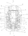
- a hydraulic braking device 100 (braking device) according to a first embodiment of the invention is shown, being part of braking system of an agricultural vehicle or the like.
- the general structure of the braking device corresponds to the one described in EP 1457400 and WO 2017/013595 , to which reference is made for a detailed description of the structure itself as well as of the operation thereof.
- the main components of the braking device 100 will be briefly illustrated by focusing on those necessary for understanding the present invention.
- the braking device 100 also called master cylinder-brake booster assembly, comprises a body 30 having an axial hole 31 with a longitudinal axis X, said body housing both the members of the master cylinder 40 and those of the brake booster 50 and being divided by a fixed disk 36 into a front bore 32 with reduced diameter, in which the piston 41 of the master cylinder 40 slides longitudinally, and a rear bore 33 which has a diameter larger than that of the front bore 32 and in which a piston 51 of the brake booster 50 slides longitudinally.
- the piston 41 of the master cylinder 40 defines, in the front bore 32, a chamber 42 (chamber of the master cylinder) which is arranged to contain oil at a control pressure depending on the force applied to the piston 41 of the master cylinder 40 by means of a brake pedal (not shown) and communicates with one or more brakes (not shown) of the vehicle.
- the piston 51 of the brake booster 50 is associated to a control piston 12 (also called spool) extending through the rear bore 33 of the axial hole 31.
- the control piston 12 comprises a first (front) end portion 12a and a second (rear) end portion 12b connected to an actuating rod 14 which in turn is connected to the brake pedal.
- Both end portions 12a, 12b of the control piston 12 preferably have a diameter larger than that of a middle portion 12c thereof, which has a reduced diameter; said middle portion 12c, having regions or steps 34a, 34b for connection to the end portions 12a, 12b with larger diameter, defines a gap 49 between the outer surface 60 of the control piston 12 and the inner surface 61 of a plunger 11 of the piston 51 of the brake booster 50.
- the plunger 11 slides on the control piston 12 exerting a sealing action against the end portions 12a, 12b thereof.
- the piston 51 of the brake booster 50 further defines, within the rear bore 33 of the axial hole 31, a first (front) pressurized chamber 52, and a second (rear) pressurized chamber 53 communicating with a pressurized oil tank (not shown).
- Passageways 54 and 55 are provided between the chambers 52 and 53 and the gap 49, respectively, said passageways passing through the plunger 11 and, under rest conditions of the device (as shown in Fig. 1 ), communicate the front chamber 52 with the rear chamber 53 through the gap 49.
- This gasketing system includes, among others, a first gasket 10, for example an O-ring, associated to the inner surface 61 of the plunger 11 and adapted to cooperate with the front end portion 12a of the control piston 12, and a second gasket 44, for example a lip-type gasket, arranged between the plunger 11 and the piston 41 of the master cylinder 40.
- a first gasket 10 for example an O-ring
- a second gasket 44 for example a lip-type gasket
- modulation area A m The cross-sectional area of the front end portion 12a of the control piston 12 with which the gasket 10 cooperates, is defined here below as modulation area A m , because the interaction between the front end portion 12a and the gasket 10 allows, in a known manner (see EP 1457400 ), the modulated communication between the front chamber 52 and the discharge chamber 43.
- the braking system 100 comprises a bushing 15 fixedly connected, for example screwed, to the front end portion 12a, distal relative to the actuating rod 14, of the control piston 12.
- the bushing 15 is associated, by means of a counter-acting member 45, for example a spring, to the piston 41 of the master cylinder 40.
- the bushing 15 is associated to a support washer 19 against which an end of the spring 45 abuts.
- the braking device 100 further comprises a gasket 16, for example an O-ring, associated to the inner surface 61 of the plunger 11 and adapted to cooperate with the bushing 15, more particularly with an outer surface 62 of the bushing 15, so as to isolate the region 47 interposed between the bushing 15 and the piston 41 of the master cylinder 40 from the discharge chamber 43.
- a gasket 16 for example an O-ring
- the gasket 16 is constrained between two washers 17a, 17b, of which the first washer 17a abuts against a shoulder 46 provided on the inner surface 61 of the plunger 11 and the second washer 17b abuts against a Seeger ring 18 associated with the inner surface 61 of the plunger 11.
- the effective cross-sectional area of the bushing 15, i.e. the cross-sectional area enclosed by the gasket 16, is the area that counter-acts the pressure that is gradually building up, in a known manner, in the region 47 by means of the brake booster.
- a second embodiment of the braking device 200 according to the invention will be described below.
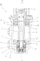
- the braking device 200 is substantially identical to the one of the first embodiment and is shown in Fig. 3 only for the part containing elements differing from the first embodiment, whereas the same reference numerals used for the first embodiment are maintained for those elements that remain unchanged.
- the braking device 200 comprises a control piston 212 in which a front end portion 212a, with which the gasket 10 cooperates, is followed by a thrust portion 215 associated, by means of a counter-acting member 45, for example a spring, with the piston 41 of the master cylinder 40. Therefore, unlike the first embodiment of the braking device 100, the braking device 200 does not comprise a bushing connected to its front end portion 212a.
- the cross-sectional area of the front end portion 212a of the control piston 212 with which the gasket 10 cooperates is defined as modulation area A m , because the interaction between the front end portion 212a and the gasket 10 allows, in a known manner (see EP 1457400 ), the modulated communication between the front chamber 52 and the discharge chamber 43.
- the braking device 200 further comprises a gasket 16, for example an O-ring, associated with the inner surface 61 of the plunger 11 and adapted to cooperate with the thrust portion 215, more particularly with an outer surface 262 of the thrust portion 215, so as to isolate the region 47 interposed between the thrust portion 215 and piston 41 of the master cylinder 40 from the discharge chamber 43.
- a gasket 16 for example an O-ring
- the gasket 16 is constrained between two washers 17a, 17b associated with the inner surface 61 of the plunger 11; for example, the first washer 17a abuts against a shoulder 46 provided on the inner surface 61 of the plunger 11 and the second washer 17b abuts against a Seeger ring 18 associated with the inner surface 61 of the plunger 11.
- the effective cross-sectional area of the thrust portion 215, i.e. the cross-sectional area enclosed by the gasket 16, is the area that counter-acts the pressure that is gradually building up, in a known manner, in the region 47 by means of the brake booster.
- control pistons 212 with different thrust portions 215, i.e. with different effective cross-sectional areas that differ from the modulation area A m defined above, it will be possible to easily vary the boosting ratio of the braking system 200, as will be better illustrated below.
- a third embodiment of the braking device 300 according to the invention will be described below.
- the braking device 300 is substantially identical to the one of the first embodiment; Fig. 4 shows only a part thereof and the same reference numerals used for the first embodiment are maintained for those elements that remain unchanged.
- the gasket 16 is mounted in a ferrule 20 associated with the inner surface 61; for example, the ferrule 20 is tightly mounted, preferably with interference fit, between a shoulder 46 provided on the inner surface 61 of the plunger 11 and a Seeger ring 18 associated to the inner surface 61 of the plunger 11.
- the effective cross-sectional area of the bushing 15, i.e. the cross-sectional area enclosed by the gasket 16, is the area that counter-acts the pressure that is gradually building up, in a known manner, in the region 47 by means of the brake booster.
- the braking device 300 it is possible to use, advantageously, bushings of different size, i.e. with different effective cross-sectional areas, so as to easily vary the boosting ration, as will be better described below.
- a further embodiment can also be provided, having a control piston comprising a thrust portion (and therefore having no bushing), as described in the second embodiment, and means for retaining the gasket cooperating with the thrust portion, said retaining means being similar to those described in the third embodiment, i.e. including a ferrule instead of washers.
- the ferrule 20 it is possible to use bushings 15 or control pistons with thrust portions 215 having effective cross-sectional areas that differ remarkably from the cross-sectional area delimited by the inner surface 61 of the plunger 11, because the ferrule 20 allows to easily compensate for such difference.
- the braking device 100, 200 or 300 is the first braking device of a pair of braking devices (substantially identical to each other) of a braking system (not shown) of an agricultural vehicle or the like.
- each braking device is associated with a corresponding brake of a rear wheel of the agricultural vehicle in order to be able to act onto a single rear brake and effect the so-called "steer-by-braking". It is therefore necessary to balance the control pressures provided by the master cylinders of the pair of braking devices in order to ensure balanced braking, i.e. a braking having substantially the same intensity on both rear wheels, when the pedals of both braking devices are actuated.
- the braking devices are equipped with balancing devices.
- the braking device 100, 200 or 300 includes a balancing device with a general structure, only briefly described below, corresponding to the one described in patent application WO 2017/013595 , in the name of the Applicant, to which reference is made for a detailed description of the structure itself as well as of the operation thereof.
- the balancing device 100, 200 or 300 comprises a stem 70 coaxial with the bushing 15 and/or the thrust portion 215 and fixed to the master cylinder 40, preferably at a front bottom 48 of the chamber 42 of the master cylinder 40.
- the stem 70, coaxial with the control piston 12 or 212, comprises an inner surface, in which a balancing channel 71 is provided, and an outer surface.
- the radial holes 73 are closed by a usually closed balancing valve, comprising, for example, a gasket 75, preferably fitted on a case 76 mounted, preferably with clearance, in the bushing 15 or in the thrust portion 215.
- a usually closed balancing valve comprising, for example, a gasket 75, preferably fitted on a case 76 mounted, preferably with clearance, in the bushing 15 or in the thrust portion 215.
- the balancing valve opens when the bushing 15 or the thrust portion 215, upon actuation of the brake pedal, and after overcoming the pre-load of the spring 45, moves towards the front portion of the master cylinder 40, so that the gasket 75, sliding along the stem 70, opens the radial holes 73, thus communicating the balancing channel 71 with a recess 77 provided within the bushing 15 or the thrust portion 215, and therefore with the chamber 42 of the master cylinder 40, through a region 47 provided between the piston 41 of the master cylinder 40 and the bushing 15 or the thrust portion 215, and through at least one radial hole 78 provided in the bushing 15 or in the thrust portion 215.
- Balancing between the control pressures existing in the chambers of the master cylinders of the two braking devices is therefore actuated mechanically after a certain stroke of the corresponding control pistons, i.e. of the corresponding brake pedals.
- the descried embodiments comprise a balancing device of the kind described, further embodiments may be envisaged having a different balancing device or no balancing device.
- the bushing may be made, for instance, without the opening 74, adapted to receive the stem 70 of the balancing device, and without the corresponding gasket 75, without departing from the scope of the invention as defined in the appended claims.
- the action of the brake booster 50 is triggered by the actuation of the brake pedal, upon which, as illustrated above, the front chamber 52 is isolated from the rear chamber 53 and is brought in modulated communication with the discharge chamber 43.
- This causes a pressure drop in the front chamber 52 and therefore a pressure difference between the front chamber 52 and the rear chamber 53, said drop causing the piston 51 of the brake booster 50 to advance towards the front portion of braking device 100, 200 or 300.
- the advancing of the piston 51 of the brake booster 50 causes in turn, by interacting with the gasket 44 in a known manner, establishment of a pressure in the region 47 interposed between the bushing 15 or the thrust portion 215 of the control piston 212 and the piston 41 of the master cylinder 40, said pressure causing advancing of the piston 41 of the master cylinder 40 and a pressure raise in the chamber 42 of the master cylinder 40, thus performing the brake boosting function.
- the brake booster 50 is characterized by a boosting ratio R ass , defined as the ratio between the boosting force F ass , i.e. the force generated by the boosting system, and the incoming force, i.e. the force exerted by the brake pedal.
- a spool is no longer the effective cross-sectional area of the control piston, but it is instead the effective cross-sectional area of the bushing 15 or the effective cross-sectional area of the thrust portion 215 of the control piston 212, which, upon their advancing towards the piston 41 of the master cylinder 40, counter-act the pressure that is gradually building up, in a known manner, in the region 47 by means of the brake booster.
- the first embodiment of the present invention it is possible to easily vary the boosting ratio by simply replacing the bushing 15 with another one having a different effective cross-sectional area and by replacing accordingly the O-ring 16, as well as the means (Seeger ring 18 and washers 17a, 17b or, alternatively, ferrule 20) fixing the gasket 16 to the plunger 11.
- This indeed, makes it possible to vary the area A spool without having to replace the whole control piston 12 and the plunger 11.
- the second embodiment of the present invention it is possible to easily vary the boosting ratio by replacing the control piston 212 with another one having a thrust portion 215 with a different effective cross-sectional area and by replacing accordingly the O-ring 16, as well as the means (Seeger ring 18 and washers 17a, 17b or, alternatively, ferrule 20) fixing the gasket 16 to the plunger 11.
- This makes it possible to vary the area A spool while maintaining unchanged the size of the front end portion 212a (and consequently of the rear end portion) of the control piston 212 without having to replace the plunger 11.
Landscapes
- Engineering & Computer Science (AREA)
- Transportation (AREA)
- Mechanical Engineering (AREA)
- Braking Systems And Boosters (AREA)
- Transmission Of Braking Force In Braking Systems (AREA)
Claims (8)
- Dispositif de freinage hydraulique comprenant un cylindre maître (40) et un servo-frein (50), dans lequel- un piston (41) du cylindre maître (40) définit une chambre (42) du cylindre maître (40), ladite chambre étant agencée pour contenir un fluide sous pression et une pression de commande, transmise à un ou plusieurs freins de véhicule, générée dans ladite chambre ;- un piston (51) du servo-frein (50) définit des première et seconde chambres sous pression (52, 53) du servo-frein (50), lesdites chambres étant associées à des moyens de communication (10, 49, 54, 55) agencés pour établir, dans des conditions de repos du dispositif de freinage, une communication entre les première et seconde chambres sous pression (52, 53) du servo-frein (50) et pour interrompre une telle communication durant le freinage ;- un piston de commande (12 ; 212), entraîné par l'actionnement d'une pédale de frein, est monté afin de pouvoir coulisser de façon serrée dans un organe plongeur (11) du piston (51) du servo-frein (50), ledit piston de commande (12 ; 212) comprenant une première partie d'extrémité (12a ; 212a) ayant une certaine superficie de section transversale (Am) et étant agencée pour coopérer avec un joint d'étanchéité (10) afin d'établir, durant le freinage, une communication modulée entre la première chambre (52) du servo-frein (50) et une chambre de refoulement (43) du cylindre maître (40) ;caractérisé en ce qu'il a une superficie de section transversale efficace (Aspool), contrant une pression existant dans une région (47) comprise entre le piston (41) du cylindre maître (40) et le piston de commande (12), différente de ladite superficie de section transversale (Am) de la première partie d'extrémité (12a ; 212a) du piston de commande (12 ; 212).
- Dispositif selon la revendication 1, comprenant une douille (15) raccordée de façon fixe à la première partie d'extrémité (12a) du piston de commande (12), ladite douille (15) comprenant une surface extérieure (62) agencée pour coopérer avec un joint d'étanchéité (16) associé à l'organe plongeur (11), pour que la superficie de section transversale efficace (Aspool) contrant la pression existant dans la région (47) comprise entre le piston (41) du cylindre maître (40) et le piston de commande (12) soit la superficie de section transversale efficace de la douille (15).
- Dispositif selon la revendication 1, dans lequel le piston de commande (212) comprend une partie de poussée (215), ladite partie de poussée (215) comprenant une surface extérieure (262) agencée pour coopérer avec un joint d'étanchéité (16) associé à l'organe plongeur (11), pour que la superficie de section transversale efficace (Aspool) contrant la pression existant dans la région (47) comprise entre le piston (41) du cylindre maître (40) et le piston de commande (12) soit la superficie de section transversale efficace de la partie de poussée (215).
- Dispositif selon la revendication 2 ou 3, dans lequel le joint d'étanchéité (16) est retenu entre une première rondelle (17a) et une seconde rondelle (17b) qui sont associées à une surface intérieure (61) de l'organe plongeur (11).
- Dispositif selon la revendication 4, dans lequel la première rondelle (17a) prend appui contre un épaulement (46) prévu sur la surface intérieure (61) de l'organe plongeur (11) et la seconde rondelle (17b) prend appui contre un anneau Seeger (18) associé à la surface intérieure (61) de l'organe plongeur (11).
- Dispositif selon la revendication 2 ou 3, dans lequel le joint d'étanchéité (16) est monté dans une virole (20) associée à une surface intérieure (61) de l'organe plongeur (11).
- Dispositif selon la revendication 6, dans lequel la virole (20) est montée de façon serrée entre un épaulement (46) prévu sur la surface intérieure (61) de l'organe plongeur (11) et un anneau Seeger (18) associé à la surface intérieure (61) de l'organe plongeur (11).
- Dispositif selon la revendication 2, dans lequel la douille (15) est associée à une rondelle de support (19) agencée pour servir de support pour un élément contrant (45) interposé entre la douille (15) et le piston (41) du cylindre maître (40).
Applications Claiming Priority (2)
| Application Number | Priority Date | Filing Date | Title |
|---|---|---|---|
| IT102017000066182A IT201700066182A1 (it) | 2017-06-14 | 2017-06-14 | Dispositivo di frenatura idraulico servoassistito |
| PCT/EP2018/064702 WO2018228856A1 (fr) | 2017-06-14 | 2018-06-05 | Dispositif de freinage hydraulique renforcé |
Publications (2)
| Publication Number | Publication Date |
|---|---|
| EP3638554A1 EP3638554A1 (fr) | 2020-04-22 |
| EP3638554B1 true EP3638554B1 (fr) | 2021-03-03 |
Family
ID=60182912
Family Applications (1)
| Application Number | Title | Priority Date | Filing Date |
|---|---|---|---|
| EP18730312.8A Active EP3638554B1 (fr) | 2017-06-14 | 2018-06-05 | Système de freinage hydraulique avec servofrein |
Country Status (4)
| Country | Link |
|---|---|
| US (1) | US11951954B2 (fr) |
| EP (1) | EP3638554B1 (fr) |
| IT (1) | IT201700066182A1 (fr) |
| WO (1) | WO2018228856A1 (fr) |
Families Citing this family (2)
| Publication number | Priority date | Publication date | Assignee | Title |
|---|---|---|---|---|
| EP4222030B1 (fr) * | 2020-10-02 | 2024-11-27 | VHIT S.p.A. | Dispositif de freinage pour guidage autonome et procédé de fonctionnement d'un tel dispositif de freinage |
| CN112810589B (zh) * | 2021-01-07 | 2022-03-22 | 东风柳州汽车有限公司 | 制动主缸以及电动汽车 |
Family Cites Families (8)
| Publication number | Priority date | Publication date | Assignee | Title |
|---|---|---|---|---|
| DE3163046D1 (en) * | 1980-04-23 | 1984-05-17 | Lucas Ind Plc | Improvements in power-operated boosters |
| DE3538763A1 (de) * | 1985-10-31 | 1987-05-07 | Teves Gmbh Alfred | Fremdenergiegespeiste bremsschlupfregelanlage eines hydraulischen fahrzeugbremssystems |
| ATE496809T1 (de) * | 2003-03-13 | 2011-02-15 | Vhit Spa | Bremskraftvorrichtung mit verbesserter bremsempfindlichkeit |
| JP3955016B2 (ja) * | 2003-12-05 | 2007-08-08 | 日信工業株式会社 | 車両用ブレーキ装置 |
| ITTO20080032A1 (it) * | 2008-01-16 | 2009-07-17 | Vhit Spa | Dispositivo idraulico di frenatura con disposizioni di sicurezza, per un trattore agricolo o veicolo similare |
| JP4638519B2 (ja) * | 2008-03-28 | 2011-02-23 | 日信工業株式会社 | 車両用ブレーキ装置 |
| IT1406552B1 (it) * | 2010-09-16 | 2014-02-28 | Vhit Spa | Dispositivo idraulico di comando della frenatura in veicoli con doppio pedale di frenatura |
| ITUB20152356A1 (it) * | 2015-07-21 | 2017-01-21 | Vhit Spa | Dispositivo di bilanciamento in corsa per sistemi di frenatura idraulica, sistema di frenatura che comprende il dispositivo e metodo del sistema di frenatura |
-
2017
- 2017-06-14 IT IT102017000066182A patent/IT201700066182A1/it unknown
-
2018
- 2018-06-05 US US16/620,564 patent/US11951954B2/en active Active
- 2018-06-05 WO PCT/EP2018/064702 patent/WO2018228856A1/fr not_active Ceased
- 2018-06-05 EP EP18730312.8A patent/EP3638554B1/fr active Active
Non-Patent Citations (1)
| Title |
|---|
| None * |
Also Published As
| Publication number | Publication date |
|---|---|
| US11951954B2 (en) | 2024-04-09 |
| EP3638554A1 (fr) | 2020-04-22 |
| IT201700066182A1 (it) | 2018-12-14 |
| WO2018228856A1 (fr) | 2018-12-20 |
| US20200198608A1 (en) | 2020-06-25 |
Similar Documents
| Publication | Publication Date | Title |
|---|---|---|
| JP4544381B2 (ja) | 車両の液圧ブレーキ装置 | |
| EP1538047B1 (fr) | Système de freinage d'un véhicule | |
| US7077482B2 (en) | Vehicle braking system | |
| US8789668B2 (en) | Master cylinder assembly, in particular for balancing a braking system of an agricultural vehicle | |
| EP2105365B1 (fr) | Appareil de freinage véhiculaire | |
| EP2223833B1 (fr) | Soupape pour réduire la course morte d'un maître cylindre | |
| US4653814A (en) | Power brake booster for a hydraulic vehicle brake system | |
| US11951954B2 (en) | Boosted hydraulic braking device | |
| US4435960A (en) | Hydraulic power boosters for vehicle hydraulic systems | |
| US10434999B2 (en) | Stroke controlled balancing device for a hydraulic braking system, braking system comprising the device and method of operating the braking system | |
| JP3640695B2 (ja) | 二段ブレーキ弁 | |
| EP4011727B1 (fr) | Dispositif de freinage | |
| JP2002137724A (ja) | マスタシリンダ | |
| JP3903579B2 (ja) | 車両用液圧ブレーキ装置 | |
| EP1538045B1 (fr) | Régulateur hydraulique | |
| JP4547787B2 (ja) | 車両用ブレーキ装置の液圧助勢装置 | |
| JP3915184B2 (ja) | 往復動部材の密封装置、及び該密封装置を備えた車両用液圧ブレーキ装置 | |
| GB2069079A (en) | Improvements in hydraulic power boosters for vehicle braking systems | |
| GB2076916A (en) | Hydraulic power booster | |
| JPH0352374B2 (fr) | ||
| EP3397536B1 (fr) | Engin hydraulique pour contrôler le freinage dans les véhicules agricoles | |
| JP2004106591A (ja) | 車両用液圧ブレーキ装置 | |
| DE10142310A1 (de) | Hydraulikbremse für ein Kraftfahrzeug | |
| JPH0376262B2 (fr) | ||
| JP2002067924A (ja) | 車両の液圧ブレーキ装置 |
Legal Events
| Date | Code | Title | Description |
|---|---|---|---|
| STAA | Information on the status of an ep patent application or granted ep patent |
Free format text: STATUS: UNKNOWN |
|
| STAA | Information on the status of an ep patent application or granted ep patent |
Free format text: STATUS: THE INTERNATIONAL PUBLICATION HAS BEEN MADE |
|
| PUAI | Public reference made under article 153(3) epc to a published international application that has entered the european phase |
Free format text: ORIGINAL CODE: 0009012 |
|
| STAA | Information on the status of an ep patent application or granted ep patent |
Free format text: STATUS: REQUEST FOR EXAMINATION WAS MADE |
|
| 17P | Request for examination filed |
Effective date: 20200114 |
|
| AK | Designated contracting states |
Kind code of ref document: A1 Designated state(s): AL AT BE BG CH CY CZ DE DK EE ES FI FR GB GR HR HU IE IS IT LI LT LU LV MC MK MT NL NO PL PT RO RS SE SI SK SM TR |
|
| AX | Request for extension of the european patent |
Extension state: BA ME |
|
| DAV | Request for validation of the european patent (deleted) | ||
| DAX | Request for extension of the european patent (deleted) | ||
| GRAP | Despatch of communication of intention to grant a patent |
Free format text: ORIGINAL CODE: EPIDOSNIGR1 |
|
| STAA | Information on the status of an ep patent application or granted ep patent |
Free format text: STATUS: GRANT OF PATENT IS INTENDED |
|
| INTG | Intention to grant announced |
Effective date: 20201020 |
|
| GRAS | Grant fee paid |
Free format text: ORIGINAL CODE: EPIDOSNIGR3 |
|
| GRAA | (expected) grant |
Free format text: ORIGINAL CODE: 0009210 |
|
| STAA | Information on the status of an ep patent application or granted ep patent |
Free format text: STATUS: THE PATENT HAS BEEN GRANTED |
|
| AK | Designated contracting states |
Kind code of ref document: B1 Designated state(s): AL AT BE BG CH CY CZ DE DK EE ES FI FR GB GR HR HU IE IS IT LI LT LU LV MC MK MT NL NO PL PT RO RS SE SI SK SM TR |
|
| REG | Reference to a national code |
Ref country code: GB Ref legal event code: FG4D |
|
| REG | Reference to a national code |
Ref country code: AT Ref legal event code: REF Ref document number: 1366892 Country of ref document: AT Kind code of ref document: T Effective date: 20210315 Ref country code: CH Ref legal event code: EP |
|
| REG | Reference to a national code |
Ref country code: DE Ref legal event code: R096 Ref document number: 602018013446 Country of ref document: DE |
|
| REG | Reference to a national code |
Ref country code: IE Ref legal event code: FG4D |
|
| REG | Reference to a national code |
Ref country code: LT Ref legal event code: MG9D |
|
| PG25 | Lapsed in a contracting state [announced via postgrant information from national office to epo] |
Ref country code: HR Free format text: LAPSE BECAUSE OF FAILURE TO SUBMIT A TRANSLATION OF THE DESCRIPTION OR TO PAY THE FEE WITHIN THE PRESCRIBED TIME-LIMIT Effective date: 20210303 Ref country code: GR Free format text: LAPSE BECAUSE OF FAILURE TO SUBMIT A TRANSLATION OF THE DESCRIPTION OR TO PAY THE FEE WITHIN THE PRESCRIBED TIME-LIMIT Effective date: 20210604 Ref country code: FI Free format text: LAPSE BECAUSE OF FAILURE TO SUBMIT A TRANSLATION OF THE DESCRIPTION OR TO PAY THE FEE WITHIN THE PRESCRIBED TIME-LIMIT Effective date: 20210303 Ref country code: BG Free format text: LAPSE BECAUSE OF FAILURE TO SUBMIT A TRANSLATION OF THE DESCRIPTION OR TO PAY THE FEE WITHIN THE PRESCRIBED TIME-LIMIT Effective date: 20210603 Ref country code: NO Free format text: LAPSE BECAUSE OF FAILURE TO SUBMIT A TRANSLATION OF THE DESCRIPTION OR TO PAY THE FEE WITHIN THE PRESCRIBED TIME-LIMIT Effective date: 20210603 Ref country code: LT Free format text: LAPSE BECAUSE OF FAILURE TO SUBMIT A TRANSLATION OF THE DESCRIPTION OR TO PAY THE FEE WITHIN THE PRESCRIBED TIME-LIMIT Effective date: 20210303 |
|
| REG | Reference to a national code |
Ref country code: NL Ref legal event code: MP Effective date: 20210303 |
|
| REG | Reference to a national code |
Ref country code: AT Ref legal event code: MK05 Ref document number: 1366892 Country of ref document: AT Kind code of ref document: T Effective date: 20210303 |
|
| PG25 | Lapsed in a contracting state [announced via postgrant information from national office to epo] |
Ref country code: LV Free format text: LAPSE BECAUSE OF FAILURE TO SUBMIT A TRANSLATION OF THE DESCRIPTION OR TO PAY THE FEE WITHIN THE PRESCRIBED TIME-LIMIT Effective date: 20210303 Ref country code: PL Free format text: LAPSE BECAUSE OF FAILURE TO SUBMIT A TRANSLATION OF THE DESCRIPTION OR TO PAY THE FEE WITHIN THE PRESCRIBED TIME-LIMIT Effective date: 20210303 Ref country code: RS Free format text: LAPSE BECAUSE OF FAILURE TO SUBMIT A TRANSLATION OF THE DESCRIPTION OR TO PAY THE FEE WITHIN THE PRESCRIBED TIME-LIMIT Effective date: 20210303 Ref country code: SE Free format text: LAPSE BECAUSE OF FAILURE TO SUBMIT A TRANSLATION OF THE DESCRIPTION OR TO PAY THE FEE WITHIN THE PRESCRIBED TIME-LIMIT Effective date: 20210303 |
|
| PG25 | Lapsed in a contracting state [announced via postgrant information from national office to epo] |
Ref country code: NL Free format text: LAPSE BECAUSE OF FAILURE TO SUBMIT A TRANSLATION OF THE DESCRIPTION OR TO PAY THE FEE WITHIN THE PRESCRIBED TIME-LIMIT Effective date: 20210303 |
|
| PG25 | Lapsed in a contracting state [announced via postgrant information from national office to epo] |
Ref country code: AT Free format text: LAPSE BECAUSE OF FAILURE TO SUBMIT A TRANSLATION OF THE DESCRIPTION OR TO PAY THE FEE WITHIN THE PRESCRIBED TIME-LIMIT Effective date: 20210303 Ref country code: SM Free format text: LAPSE BECAUSE OF FAILURE TO SUBMIT A TRANSLATION OF THE DESCRIPTION OR TO PAY THE FEE WITHIN THE PRESCRIBED TIME-LIMIT Effective date: 20210303 Ref country code: EE Free format text: LAPSE BECAUSE OF FAILURE TO SUBMIT A TRANSLATION OF THE DESCRIPTION OR TO PAY THE FEE WITHIN THE PRESCRIBED TIME-LIMIT Effective date: 20210303 Ref country code: CZ Free format text: LAPSE BECAUSE OF FAILURE TO SUBMIT A TRANSLATION OF THE DESCRIPTION OR TO PAY THE FEE WITHIN THE PRESCRIBED TIME-LIMIT Effective date: 20210303 |
|
| PG25 | Lapsed in a contracting state [announced via postgrant information from national office to epo] |
Ref country code: SK Free format text: LAPSE BECAUSE OF FAILURE TO SUBMIT A TRANSLATION OF THE DESCRIPTION OR TO PAY THE FEE WITHIN THE PRESCRIBED TIME-LIMIT Effective date: 20210303 Ref country code: PT Free format text: LAPSE BECAUSE OF FAILURE TO SUBMIT A TRANSLATION OF THE DESCRIPTION OR TO PAY THE FEE WITHIN THE PRESCRIBED TIME-LIMIT Effective date: 20210705 Ref country code: RO Free format text: LAPSE BECAUSE OF FAILURE TO SUBMIT A TRANSLATION OF THE DESCRIPTION OR TO PAY THE FEE WITHIN THE PRESCRIBED TIME-LIMIT Effective date: 20210303 Ref country code: IS Free format text: LAPSE BECAUSE OF FAILURE TO SUBMIT A TRANSLATION OF THE DESCRIPTION OR TO PAY THE FEE WITHIN THE PRESCRIBED TIME-LIMIT Effective date: 20210703 |
|
| REG | Reference to a national code |
Ref country code: DE Ref legal event code: R097 Ref document number: 602018013446 Country of ref document: DE |
|
| PLBE | No opposition filed within time limit |
Free format text: ORIGINAL CODE: 0009261 |
|
| STAA | Information on the status of an ep patent application or granted ep patent |
Free format text: STATUS: NO OPPOSITION FILED WITHIN TIME LIMIT |
|
| PG25 | Lapsed in a contracting state [announced via postgrant information from national office to epo] |
Ref country code: ES Free format text: LAPSE BECAUSE OF FAILURE TO SUBMIT A TRANSLATION OF THE DESCRIPTION OR TO PAY THE FEE WITHIN THE PRESCRIBED TIME-LIMIT Effective date: 20210303 Ref country code: DK Free format text: LAPSE BECAUSE OF FAILURE TO SUBMIT A TRANSLATION OF THE DESCRIPTION OR TO PAY THE FEE WITHIN THE PRESCRIBED TIME-LIMIT Effective date: 20210303 Ref country code: AL Free format text: LAPSE BECAUSE OF FAILURE TO SUBMIT A TRANSLATION OF THE DESCRIPTION OR TO PAY THE FEE WITHIN THE PRESCRIBED TIME-LIMIT Effective date: 20210303 Ref country code: MC Free format text: LAPSE BECAUSE OF FAILURE TO SUBMIT A TRANSLATION OF THE DESCRIPTION OR TO PAY THE FEE WITHIN THE PRESCRIBED TIME-LIMIT Effective date: 20210303 |
|
| REG | Reference to a national code |
Ref country code: CH Ref legal event code: PL |
|
| 26N | No opposition filed |
Effective date: 20211206 |
|
| PG25 | Lapsed in a contracting state [announced via postgrant information from national office to epo] |
Ref country code: SI Free format text: LAPSE BECAUSE OF FAILURE TO SUBMIT A TRANSLATION OF THE DESCRIPTION OR TO PAY THE FEE WITHIN THE PRESCRIBED TIME-LIMIT Effective date: 20210303 |
|
| REG | Reference to a national code |
Ref country code: BE Ref legal event code: MM Effective date: 20210630 |
|
| PG25 | Lapsed in a contracting state [announced via postgrant information from national office to epo] |
Ref country code: LU Free format text: LAPSE BECAUSE OF NON-PAYMENT OF DUE FEES Effective date: 20210605 |
|
| PG25 | Lapsed in a contracting state [announced via postgrant information from national office to epo] |
Ref country code: LI Free format text: LAPSE BECAUSE OF NON-PAYMENT OF DUE FEES Effective date: 20210630 Ref country code: IT Free format text: LAPSE BECAUSE OF FAILURE TO SUBMIT A TRANSLATION OF THE DESCRIPTION OR TO PAY THE FEE WITHIN THE PRESCRIBED TIME-LIMIT Effective date: 20210303 Ref country code: IE Free format text: LAPSE BECAUSE OF NON-PAYMENT OF DUE FEES Effective date: 20210605 Ref country code: CH Free format text: LAPSE BECAUSE OF NON-PAYMENT OF DUE FEES Effective date: 20210630 |
|
| PG25 | Lapsed in a contracting state [announced via postgrant information from national office to epo] |
Ref country code: IS Free format text: LAPSE BECAUSE OF FAILURE TO SUBMIT A TRANSLATION OF THE DESCRIPTION OR TO PAY THE FEE WITHIN THE PRESCRIBED TIME-LIMIT Effective date: 20210703 |
|
| PG25 | Lapsed in a contracting state [announced via postgrant information from national office to epo] |
Ref country code: BE Free format text: LAPSE BECAUSE OF NON-PAYMENT OF DUE FEES Effective date: 20210630 |
|
| GBPC | Gb: european patent ceased through non-payment of renewal fee |
Effective date: 20220605 |
|
| PG25 | Lapsed in a contracting state [announced via postgrant information from national office to epo] |
Ref country code: GB Free format text: LAPSE BECAUSE OF NON-PAYMENT OF DUE FEES Effective date: 20220605 |
|
| PG25 | Lapsed in a contracting state [announced via postgrant information from national office to epo] |
Ref country code: CY Free format text: LAPSE BECAUSE OF FAILURE TO SUBMIT A TRANSLATION OF THE DESCRIPTION OR TO PAY THE FEE WITHIN THE PRESCRIBED TIME-LIMIT Effective date: 20210303 |
|
| P01 | Opt-out of the competence of the unified patent court (upc) registered |
Effective date: 20230601 |
|
| PG25 | Lapsed in a contracting state [announced via postgrant information from national office to epo] |
Ref country code: HU Free format text: LAPSE BECAUSE OF FAILURE TO SUBMIT A TRANSLATION OF THE DESCRIPTION OR TO PAY THE FEE WITHIN THE PRESCRIBED TIME-LIMIT; INVALID AB INITIO Effective date: 20180605 |
|
| PG25 | Lapsed in a contracting state [announced via postgrant information from national office to epo] |
Ref country code: MK Free format text: LAPSE BECAUSE OF FAILURE TO SUBMIT A TRANSLATION OF THE DESCRIPTION OR TO PAY THE FEE WITHIN THE PRESCRIBED TIME-LIMIT Effective date: 20210303 |
|
| PG25 | Lapsed in a contracting state [announced via postgrant information from national office to epo] |
Ref country code: MT Free format text: LAPSE BECAUSE OF FAILURE TO SUBMIT A TRANSLATION OF THE DESCRIPTION OR TO PAY THE FEE WITHIN THE PRESCRIBED TIME-LIMIT Effective date: 20210303 |
|
| PGFP | Annual fee paid to national office [announced via postgrant information from national office to epo] |
Ref country code: DE Payment date: 20250516 Year of fee payment: 8 |
|
| PGFP | Annual fee paid to national office [announced via postgrant information from national office to epo] |
Ref country code: FR Payment date: 20250522 Year of fee payment: 8 |
|
| PG25 | Lapsed in a contracting state [announced via postgrant information from national office to epo] |
Ref country code: TR Free format text: LAPSE BECAUSE OF FAILURE TO SUBMIT A TRANSLATION OF THE DESCRIPTION OR TO PAY THE FEE WITHIN THE PRESCRIBED TIME-LIMIT Effective date: 20210303 |