EP3638593B1 - Conteneur doté d'un fond fourni avec des encoches - Google Patents
Conteneur doté d'un fond fourni avec des encoches Download PDFInfo
- Publication number
- EP3638593B1 EP3638593B1 EP18728659.6A EP18728659A EP3638593B1 EP 3638593 B1 EP3638593 B1 EP 3638593B1 EP 18728659 A EP18728659 A EP 18728659A EP 3638593 B1 EP3638593 B1 EP 3638593B1
- Authority
- EP
- European Patent Office
- Prior art keywords
- notches
- container
- container according
- series
- principal
- Prior art date
- Legal status (The legal status is an assumption and is not a legal conclusion. Google has not performed a legal analysis and makes no representation as to the accuracy of the status listed.)
- Active
Links
Images

Classifications
-
- B—PERFORMING OPERATIONS; TRANSPORTING
- B65—CONVEYING; PACKING; STORING; HANDLING THIN OR FILAMENTARY MATERIAL
- B65D—CONTAINERS FOR STORAGE OR TRANSPORT OF ARTICLES OR MATERIALS, e.g. BAGS, BARRELS, BOTTLES, BOXES, CANS, CARTONS, CRATES, DRUMS, JARS, TANKS, HOPPERS, FORWARDING CONTAINERS; ACCESSORIES, CLOSURES, OR FITTINGS THEREFOR; PACKAGING ELEMENTS; PACKAGES
- B65D1/00—Rigid or semi-rigid containers having bodies formed in one piece, e.g. by casting metallic material, by moulding plastics, by blowing vitreous material, by throwing ceramic material, by moulding pulped fibrous material or by deep-drawing operations performed on sheet material
- B65D1/02—Bottles or similar containers with necks or like restricted apertures, designed for pouring contents
- B65D1/0223—Bottles or similar containers with necks or like restricted apertures, designed for pouring contents characterised by shape
- B65D1/0261—Bottom construction
- B65D1/0284—Bottom construction having a discontinuous contact surface, e.g. discrete feet
-
- B—PERFORMING OPERATIONS; TRANSPORTING
- B65—CONVEYING; PACKING; STORING; HANDLING THIN OR FILAMENTARY MATERIAL
- B65D—CONTAINERS FOR STORAGE OR TRANSPORT OF ARTICLES OR MATERIALS, e.g. BAGS, BARRELS, BOTTLES, BOXES, CANS, CARTONS, CRATES, DRUMS, JARS, TANKS, HOPPERS, FORWARDING CONTAINERS; ACCESSORIES, CLOSURES, OR FITTINGS THEREFOR; PACKAGING ELEMENTS; PACKAGES
- B65D1/00—Rigid or semi-rigid containers having bodies formed in one piece, e.g. by casting metallic material, by moulding plastics, by blowing vitreous material, by throwing ceramic material, by moulding pulped fibrous material or by deep-drawing operations performed on sheet material
- B65D1/02—Bottles or similar containers with necks or like restricted apertures, designed for pouring contents
- B65D1/0207—Bottles or similar containers with necks or like restricted apertures, designed for pouring contents characterised by material, e.g. composition, physical features
-
- B—PERFORMING OPERATIONS; TRANSPORTING
- B65—CONVEYING; PACKING; STORING; HANDLING THIN OR FILAMENTARY MATERIAL
- B65D—CONTAINERS FOR STORAGE OR TRANSPORT OF ARTICLES OR MATERIALS, e.g. BAGS, BARRELS, BOTTLES, BOXES, CANS, CARTONS, CRATES, DRUMS, JARS, TANKS, HOPPERS, FORWARDING CONTAINERS; ACCESSORIES, CLOSURES, OR FITTINGS THEREFOR; PACKAGING ELEMENTS; PACKAGES
- B65D2501/00—Containers having bodies formed in one piece
- B65D2501/0009—Bottles or similar containers with necks or like restricted apertures designed for pouring contents
- B65D2501/0018—Ribs
- B65D2501/0036—Hollow circonferential ribs
Definitions
- the invention relates to improvements made to containers, in particular bottles or jars, obtainable by blowing, blow-molding or stretch blow-molding of preforms made of thermoplastic material such as PET (polyethylene terephthalate), PE (polyethylene), or PEF (polyethylene furanoate).
- PET polyethylene terephthalate
- PE polyethylene
- PEF polyethylene furanoate
- Manufacturing of containers by blow-molding ordinarily consists of inserting, into a mold with the imprint of the container, a preform previously heated to a temperature above the glass transition temperature of the thermoplastic material, and of injecting into the preform a fluid (particularly a gas such as air but it can also be an incompressible fluid such as water) under pressure.
- the blowing can be completed by a preliminary stretching of the preform by means of a sliding rod.
- Such containers have a body extending between, at the top, a neck and, at the bottom, a base adapted for withstanding without marked deformation the hydrostatic pressure due to the liquid column which rises above them.
- Containers intended to contain a still liquid are, in the majority of cases, provided with a rounded base in the general form of a spherical cap having a concavity turned outwards and of relatively small height.
- Such bases are often provided with substantially radially radiating grooves (also called ribs) which are distributed around a central recess, said grooves having various shapes and optionally extending possibly onto the lower part of the wall of the body in order to reinforce the foundation (peripheral zone with which the base rests on a support).
- Such bases in addition to withstanding the hydrostatic pressure due to the liquid column which rises above them, should offer sufficient resistance to withstand any additional stress, even though small, that may be due for example to palletization, logistic transportation or storage.
- a hit on an edge of the container, a shock or a bump may result in a crack or in a rift in the container, especially at the base location, leading to a loss of water from the container rending to container useless.
- a first objective of the present invention is to propose a container, the base of which offers good resistance to denting and cracks.
- a second objective is to propose a container for which the optimized structure and geometry of the base gives it a good compromise between blowability, lightness and rigidity while avoiding generation of cracks at the container base location in case of bumps or shocks.
- the invention provides a plastic container according to Claim 1, said container having a body and a bottom base extending from a lower end of the body in which the bottom base comprises a series of principal reinforcing grooves extending radially from the central zone to at least the peripheral seat and a series of notches, in which at least one of the series of principal reinforcing grooves is locally interrupted by at least one of the series of notches
- thermoplastic material in the base is better controlled.
- the notches allow reducing the stiffness of the base by increasing flexibility in the zone comprising a high level of amorphous material around the central zone.
- the series of notches are arranged on a circular line (L) concentric with the injection point. This arrangement is sufficient for small container to improve the resistance to breakage of the base due to denting and shocks.
- the series of notches are part of a circular groove (C) concentric with the injection point. Thanks to the circular groove (C), the decoupling is complete.
- the series of notches are arranged on the perimeter of a circular groove (C) concentric with the injection point.
- the circular groove (C) is adding its advantages to the ones of the notches.
- the notches interrupt the principal reinforcing grooves in an arcuate manner.
- the circular line (L) or the groove (C) has a radius within the range from 10 mm to 40 mm.
- the proposed range takes into account the base dimension according to the volume of the container.
- the at least one of the series of principal reinforcing grooves is locally interrupted by at least one of the series of notches along an axis that is perpendicular to the main axis of said at least one of the series of principal reinforcing grooves.
- each principal reinforcing groove is interrupted by one notch.
- each principal reinforcing groove is interrupted by at least two notches. This may be the case for volumes higher than 2L.
- the notches have a base dimension, corresponding to their opened side, ranging from 2mm to 6 mm
- the notches have a triangular profile in cross section. This type of profile is quite easy to blow and very efficient for decoupling purpose.
- the notches have a depth within the range from 0.5mm to the depth of the principal reinforcing groove.
- the principal reinforcing grooves have an open angle comprised within the range from 20° to 80°.
- the proposed base further comprises intermediate reinforcing grooves extending radially from the concave arch or the central zone to at least the peripheral seat, said intermediate reinforcing grooves being interspersed between the principle reinforcing grooves.
- intermediate reinforcing grooves allows diminishing the surface with flat structure on the base thereby reinforcing the bottom base of the container to resist pressure and denting.
- the bottom base comprises a fully structured surface contributes to avoiding reversal of the bottom base and to resisting to pressure.
- the principal and/or intermediate reinforcing grooves extend locally over the peripheral seat and rise up over the bottom base of the container to the body of the container.
- This specific feature allows having good resistance to lateral denting.
- the proposed features allow improving the performance of the base versus a base that does not have the proposed notches.
- the improved performances are particularly visible on the vertical drop test: no more breakage at the location of / or in alignment with the injection point is observed.
- FIG. 1 shows a general view of a container 1, a bottle in this instance, produced by stretch blow molding a preform made of thermoplastic material, for example PET (polyethylene terephthalate, PE (polyethylene) or PEF (polyethylene furanoate).
- PET polyethylene terephthalate
- PE polyethylene
- PEF polyethylene furanoate
- Said container 1 comprises, at an upper end, a neck 2, provided with a mouth 3.
- the container 1 comprises in its upper part a shoulder 4 that widens out in the direction opposite to the neck 2, said shoulder 4 being extended by a lateral wall or body 5, of a shape generally cylindrical in revolution around a main axis X of the container 1.
- the container 1 further comprises at the bottom, a base 6 which extends, opposite the neck 2, from a lower end of the body 5.
- the base 6 comprises a peripheral seat 7 in the form of an annular ridge which extends substantially axially in the extension of the body 5.
- the seat 7 terminates in a laying plane 8 (also called seating plane) perpendicular to the axis X of the container 1, said seating plane 8 defining the lower end of the container 1 and enabling it to be seated upright on a flat surface.
- D denotes the diameter of the seating plane 8
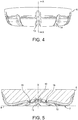
- FIGS. 2 to 5 will be jointly described in the following part.
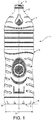
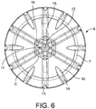
- FIGS 2 and 3 presenting a bottom view and perspective view of the base of container of FIG. 1 integrating the features of the invention, show the bottom base 6 which from its peripheral part 7 to its center comprises the peripheral seat 7, already described, a concave arch 10, a central zone 11 comprising in the middle an injection point 12.
- Said injection point 12 being an amorphous pellet resulting from the formation of the preform and located in its center.
- the concave arch 10 has a rounded general shape. It is in the form of a substantially spherical dome with the concavity turned towards the exterior of the container 1 in the absence of stress, i.e. in the absence of contents in the container 1.
- the arch 10 extends from the seat 7, to the central zone 11 of the bottom 6 forming a bump projecting towards the interior of the container 1.
- the base 6 comprises a series of principle reinforcing grooves 13.
- Said principal reinforcing grooves 13 are hollow towards the interior of the container 1. They extend radially from the central zone 11 to at least the peripheral seat 7 defining for each principal reinforcing groove a main axis (G, G', G").
- the principal reinforcing grooves 13 extend beyond the seat 7, rising laterally over a lower part of the body 5 of the container 1.
- the principal grooves 13 extend radially over the entire arch 10, over the peripheral seat 7 and part of the body 5. It will therefore be understood that the seating plane 8 is discontinuous because it is interrupted at each principal groove 13. In the present example, there are six principle grooves 13, but this number could be higher, specifically seven or eight for a container with a different volume.
- the reinforcing grooves 13 have an open angle comprised within the range from 20° to 80°.
- the body 6 is further provided with a series of intermediate reinforcing grooves 14 situated between the principal grooves 13, and which extend locally over the concave arch 10 that they thus contribute to rigidifying.
- the intermediate ribs of 14 extend from the central region 15 of the concave arch 10 towards the exterior beyond the peripheral seat 7, rising laterally over a lower part of the body 5, like the principal reinforcing grooves 13.
- the intermediate reinforcing grooves 14 may extend from the central region 15 to the peripheral seat 7 without extending over it.
- the intermediate reinforcing grooves 14 are each interposed between two adjacent principle reinforcing grooves 13.
- Both principal 13 and intermediate 14 reinforcing grooves rise up to the body 5 of the container 1 to a height comprised within the range from 9 to 15 mm with respect to the laying plan 8.
- the bottom base 6 further comprises a series of notches 15.
- the notches 15 locally interrupt the principal reinforcing grooves 13 so as to provide a discontinuity in the principal reinforcing grooves 13.
- the notches 15 are arranged on a circular line L concentric with the injection point 12 located on the concave arch 10 proximate the central zone11.
- This line may be a virtual line or a line coming from an imprint in the mold (as presented in FIGS. 2 and 3 ) in which the preform is introduced for the bi-orientation process (blow-molding process).
- the notches are positioned along a circular line L located on the concave arch 10 proximate the central zone 11.
- the notches 15 interrupt the principal reinforcing grooves 13in the concave arch 10 in an arcuate manner.
- the injection point 12 and the central zone 11 comprise a high level of amorphous thermoplastic material (as they are not very much stretched during the bi-orientation process), which breaks easily when it is under stress (pressure or shock).
- the decoupling allows creating an additional stretched zone in which the thermoplastic molecules are bi-oriented (and not anymore in an amorphous state). This bi-orientation generates a certain rigidity in the material while still allowing the material to undergo elastic deformation (which is not the case when the material is in the amorphous state).
- the notches are part of a circular groove C concentric with the injection point 12.
- the notches interrupt the principal reinforcing grooves 13 in an arcuate manner.
- the circular groove C may have a different profile than the profile of the notches 15 and the notches may be located at the perimeter of the circular groove C
- Both, the circular line L and the circular circle C are centered on the injection point 12. They have a radius ranging from 10 mm to about 40 mm.
- the notches 15 have a base dimension (open side of the notches) ranging from 2mm to 6 mm.
- the notches 15 have a depth within the range from 0.5mm to the depth of the principal reinforcing groove 13.
- the depth of the principal reinforcing groove 13 may rise up to 5mm or more according to the volume of the container.
- each principal reinforcing groove 13 is interrupted by one notch 15. Thereby, decoupling between the central zone 11 and the concave arch 10 is realized.
- each principal reinforcing groove 13 is interrupted by at least two notches 15 leading to at least two decoupling.
- the notches have a triangular asymmetric profile in cross section (see FIG. 5 ) but the profile may vary in shape, geometry and dimension.
- profile is symmetric or asymmetric and /or having trapezoidal or square geometry, but other alternatives are available.
- At least one of the series of principal reinforcing grooves 13 is locally interrupted by at least one of the series of notches 15 along an axis P, P', P" that is perpendicular to the main axis G, G', G" of said at least one of the series of principal reinforcing grooves 13.
- the base 6 comprising the notches 15 of the invention allows decoupling the amorphous zone (incorporating the injection point and part of the central zone) and the zone in which the thermoplastic material has been bi-oriented by creating an additional zone that need to be stretched.
- the container 1 provided with the proposed base 6 offers a good compromise between the mechanical performance (i.e. the ability of the container 1 to resist deformations and denting) and blowability (i.e. the ability of the container 1 to be formed by blowing).
Landscapes
- Engineering & Computer Science (AREA)
- Ceramic Engineering (AREA)
- Mechanical Engineering (AREA)
- Containers Having Bodies Formed In One Piece (AREA)
- Details Of Rigid Or Semi-Rigid Containers (AREA)
Claims (15)
- Récipient (1) en matière plastique, muni d'un corps (5) et d'une base inférieure (6) s'étendant à partir d'une extrémité inférieure du corps (5), la base inférieure (6) comprenant :- une zone centrale annulaire (11) concentrique à un point d'injection (12) situé approximativement au centre de la base inférieure (6) ;- un siège périphérique (7) définissant un plan de pose (8) ;- un arc concave (10) qui s'étend de la périphérie de la zone centrale (11) jusqu'au siège périphérique (7) et ayant une forme générale arrondie avec une concavité tournée vers l'extérieur du récipient (1) ;- une série de rainures principales de renforcement (13) qui s'étendent radialement depuis la zone centrale (11) au moins jusqu'au siège périphérique (7) définissant pour chaque rainure principale de renforcement un axe principal (G, G', G"),
caractérisé en ce que la base inférieure (6) comprend en outre une série d'encoches (15) et en ce qu'au moins l'une de la série d'encoches (15) interrompt localement au moins l'une de la série de rainures principales de renforcement (13). - Récipient selon la revendication 1, caractérisé en ce que la série d'encoches est disposée sur une ligne circulaire (L) concentrique au point d'injection (12).
- Récipient selon la revendication 1 ou 2, caractérisé en ce que la série d'encoches fait partie d'une rainure circulaire (C) concentrique au point d'injection (12).
- Récipient selon l'une quelconque des revendications 1 à 3, caractérisé en ce que la série d'encoches est disposée sur le pourtour d'une rainure circulaire (C) concentrique au point d'injection (12).
- Récipient selon l'une quelconque des revendications 1 à 4, caractérisé en ce que les encoches interrompent les rainures principales de renforcement de manière arquée.
- Récipient selon l'une quelconque des revendications 1 à 5, caractérisé en ce que la ligne circulaire (L) ou la rainure circulaire (C) présente un rayon compris entre 10 mm et 40 mm.
- Récipient selon la revendication 1, caractérisé en ce que l'au moins une de la série de rainures principales de renforcement (13) est localement interrompue par au moins une de la série d'encoches (15) suivant un axe (P, P', P") qui est perpendiculaire à l'axe principal (G, G', G") de ladite au moins une de la série de rainures principales de renforcement (13).
- Récipient selon l'une quelconque des revendications 1 à 7, caractérisé en ce que chaque rainure principale de renforcement (13) est interrompue par une encoche (15).
- Récipient selon l'une quelconque des revendications 1 à 7, caractérisé en ce que chaque rainure principale de renforcement (13) est interrompue par au moins deux encoches (15).
- Récipient selon l'une quelconque des revendications 1 à 9, caractérisé en ce que les encoches ont une dimensions de base comprise entre 2 mm et 6 mm.
- Récipient selon l'une quelconque des revendications 1 à 10, caractérisé en ce que les encoches ont un profil triangulaire en section transversale.
- Récipient selon l'une quelconque des revendications 1 à 11, caractérisé en ce que les encoches ont une profondeur comprise entre 0,5 mm et la profondeur de la rainure principale de renforcement (13).
- Récipient selon l'une quelconque des revendications 1 à 12, caractérisé en ce que les rainures principales de renforcement (13) présentent un angle ouvert compris entre 20° et 80°.
- Récipient selon l'une quelconque des revendications 1 à 13, caractérisé en ce qu' il comprend en outre des rainures intermédiaires de renforcement (14) s'étendant radialement depuis l'arceau concave (10) ou la zone centrale (11) jusqu'au moins au siège périphérique (7), lesdites rainures intermédiaires de renforcement (14) étant intercalées entre les rainures principales de renforcement (13).
- Récipient selon l'une quelconque des revendications 1 à 14, caractérisé en ce que des rainures principales et/ou intermédiaires de renforcement s'étendent localement par dessus le siège périphérique et remontent sur la base inférieure du récipient jusqu'au corps du récipient.
Applications Claiming Priority (2)
| Application Number | Priority Date | Filing Date | Title |
|---|---|---|---|
| EP17176461 | 2017-06-16 | ||
| PCT/EP2018/065263 WO2018228962A1 (fr) | 2017-06-16 | 2018-06-11 | Récipient ayant une base inférieure comportant des encoches |
Publications (2)
| Publication Number | Publication Date |
|---|---|
| EP3638593A1 EP3638593A1 (fr) | 2020-04-22 |
| EP3638593B1 true EP3638593B1 (fr) | 2021-07-21 |
Family
ID=59093395
Family Applications (1)
| Application Number | Title | Priority Date | Filing Date |
|---|---|---|---|
| EP18728659.6A Active EP3638593B1 (fr) | 2017-06-16 | 2018-06-11 | Conteneur doté d'un fond fourni avec des encoches |
Country Status (7)
| Country | Link |
|---|---|
| US (1) | US20200189785A1 (fr) |
| EP (1) | EP3638593B1 (fr) |
| CN (1) | CN110770134A (fr) |
| AR (1) | AR112165A1 (fr) |
| CA (1) | CA3067272A1 (fr) |
| MX (1) | MX2019014094A (fr) |
| WO (1) | WO2018228962A1 (fr) |
Families Citing this family (7)
| Publication number | Priority date | Publication date | Assignee | Title |
|---|---|---|---|---|
| MX2020011255A (es) * | 2018-04-26 | 2020-11-12 | Graham Packaging Co | Recipiente de relleno presurizado resistente al agrietamiento del anillo de pie. |
| US11155379B2 (en) * | 2018-12-21 | 2021-10-26 | Colgate-Palmolive Company | Container apparatus |
| JP7370248B2 (ja) * | 2019-12-27 | 2023-10-27 | 株式会社吉野工業所 | ボトル |
| AU2021202920A1 (en) * | 2020-05-08 | 2021-11-25 | Orora Packaging Australia Pty Ltd | A bottle, and an insert and a mould for making the bottle |
| JP2023540167A (ja) | 2020-09-17 | 2023-09-22 | 広州達意隆包装機械股▲フン▼有限公司 | ブロー成形金型、ボトルブロー機及びプラスチックボトル |
| FR3120353B1 (fr) | 2021-03-02 | 2024-07-05 | Sa Des Eaux Minerales Devian Et En Abrege S A E M E | Bouteille à fond amélioré |
| US12129072B2 (en) * | 2021-11-30 | 2024-10-29 | Pepsico, Inc. | Flexible base for aseptic-fill bottles |
Family Cites Families (4)
| Publication number | Priority date | Publication date | Assignee | Title |
|---|---|---|---|---|
| FR2904809B1 (fr) * | 2006-08-08 | 2008-10-24 | Sidel Participations | Fond de corps creux obtenu par soufflage ou etirage soufflage d'une preforme en materiau thermoplastique, corps creux comprenant un tel fond |
| FR2991302B1 (fr) * | 2012-05-31 | 2014-07-04 | Sidel Participations | Recipient ayant un fond muni d'une voute a decrochement |
| FR2998877B1 (fr) * | 2012-11-30 | 2014-12-26 | Sidel Participations | Recipient ayant un fond muni d'une voute a double decrochement |
| FR3003848B1 (fr) * | 2013-04-02 | 2015-04-17 | Sidel Participations | Recipient ayant un fond muni d'une voute a decrochement |
-
2018
- 2018-06-11 US US16/621,059 patent/US20200189785A1/en not_active Abandoned
- 2018-06-11 MX MX2019014094A patent/MX2019014094A/es unknown
- 2018-06-11 CA CA3067272A patent/CA3067272A1/fr active Pending
- 2018-06-11 EP EP18728659.6A patent/EP3638593B1/fr active Active
- 2018-06-11 WO PCT/EP2018/065263 patent/WO2018228962A1/fr not_active Ceased
- 2018-06-11 CN CN201880039471.XA patent/CN110770134A/zh active Pending
- 2018-06-15 AR ARP180101690A patent/AR112165A1/es active IP Right Grant
Also Published As
| Publication number | Publication date |
|---|---|
| CN110770134A (zh) | 2020-02-07 |
| MX2019014094A (es) | 2020-02-07 |
| AR112165A1 (es) | 2019-09-25 |
| EP3638593A1 (fr) | 2020-04-22 |
| WO2018228962A1 (fr) | 2018-12-20 |
| CA3067272A1 (fr) | 2018-12-20 |
| US20200189785A1 (en) | 2020-06-18 |
Similar Documents
| Publication | Publication Date | Title |
|---|---|---|
| EP3638593B1 (fr) | Conteneur doté d'un fond fourni avec des encoches | |
| US11987416B2 (en) | Plastic container | |
| US9758271B2 (en) | Container having a bottom provided with a vault with a double indentation | |
| ES2981987T3 (es) | Recipiente de plástico con costillas de profundidad variable | |
| CN104349983B (zh) | 具有带台阶式拱部的底部的容器 | |
| CN105050903B (zh) | 具有双拱式可变形底部的容器 | |
| US20060131257A1 (en) | Plastic container with champagne style base | |
| US20010027978A1 (en) | Container with structural ribs | |
| AU2018283342B2 (en) | Container bottom base provided with a bi-concave arch | |
| US20160288946A1 (en) | Container having a bottom provided with a stepped arch | |
| JP5970905B2 (ja) | プラスチックボトル | |
| EP3099582A1 (fr) | Contenant autoportant amélioré | |
| JP4099923B2 (ja) | 薄肉ブローボトル | |
| JP5631183B2 (ja) | プリフォーム | |
| JP2016132501A (ja) | プラスチックボトル | |
| WO2015189127A1 (fr) | Bouteille et base | |
| JP2002225834A (ja) | 薄肉ブローボトル | |
| JP7309279B2 (ja) | 合成樹脂製容器 | |
| JP2018030630A (ja) | プラスチックボトル、及び充填体 | |
| JP2021095182A (ja) | 合成樹脂製容器 | |
| JP2019043593A (ja) | 耐圧ボトル |
Legal Events
| Date | Code | Title | Description |
|---|---|---|---|
| STAA | Information on the status of an ep patent application or granted ep patent |
Free format text: STATUS: UNKNOWN |
|
| STAA | Information on the status of an ep patent application or granted ep patent |
Free format text: STATUS: THE INTERNATIONAL PUBLICATION HAS BEEN MADE |
|
| PUAI | Public reference made under article 153(3) epc to a published international application that has entered the european phase |
Free format text: ORIGINAL CODE: 0009012 |
|
| STAA | Information on the status of an ep patent application or granted ep patent |
Free format text: STATUS: REQUEST FOR EXAMINATION WAS MADE |
|
| 17P | Request for examination filed |
Effective date: 20200116 |
|
| AK | Designated contracting states |
Kind code of ref document: A1 Designated state(s): AL AT BE BG CH CY CZ DE DK EE ES FI FR GB GR HR HU IE IS IT LI LT LU LV MC MK MT NL NO PL PT RO RS SE SI SK SM TR |
|
| AX | Request for extension of the european patent |
Extension state: BA ME |
|
| DAV | Request for validation of the european patent (deleted) | ||
| DAX | Request for extension of the european patent (deleted) | ||
| GRAP | Despatch of communication of intention to grant a patent |
Free format text: ORIGINAL CODE: EPIDOSNIGR1 |
|
| STAA | Information on the status of an ep patent application or granted ep patent |
Free format text: STATUS: GRANT OF PATENT IS INTENDED |
|
| INTG | Intention to grant announced |
Effective date: 20210217 |
|
| GRAS | Grant fee paid |
Free format text: ORIGINAL CODE: EPIDOSNIGR3 |
|
| GRAA | (expected) grant |
Free format text: ORIGINAL CODE: 0009210 |
|
| STAA | Information on the status of an ep patent application or granted ep patent |
Free format text: STATUS: THE PATENT HAS BEEN GRANTED |
|
| AK | Designated contracting states |
Kind code of ref document: B1 Designated state(s): AL AT BE BG CH CY CZ DE DK EE ES FI FR GB GR HR HU IE IS IT LI LT LU LV MC MK MT NL NO PL PT RO RS SE SI SK SM TR |
|
| REG | Reference to a national code |
Ref country code: GB Ref legal event code: FG4D |
|
| REG | Reference to a national code |
Ref country code: CH Ref legal event code: EP |
|
| REG | Reference to a national code |
Ref country code: DE Ref legal event code: R096 Ref document number: 602018020448 Country of ref document: DE |
|
| REG | Reference to a national code |
Ref country code: AT Ref legal event code: REF Ref document number: 1412413 Country of ref document: AT Kind code of ref document: T Effective date: 20210815 |
|
| REG | Reference to a national code |
Ref country code: IE Ref legal event code: FG4D |
|
| REG | Reference to a national code |
Ref country code: LT Ref legal event code: MG9D |
|
| REG | Reference to a national code |
Ref country code: NL Ref legal event code: MP Effective date: 20210721 |
|
| REG | Reference to a national code |
Ref country code: AT Ref legal event code: MK05 Ref document number: 1412413 Country of ref document: AT Kind code of ref document: T Effective date: 20210721 |
|
| PG25 | Lapsed in a contracting state [announced via postgrant information from national office to epo] |
Ref country code: RS Free format text: LAPSE BECAUSE OF FAILURE TO SUBMIT A TRANSLATION OF THE DESCRIPTION OR TO PAY THE FEE WITHIN THE PRESCRIBED TIME-LIMIT Effective date: 20210721 Ref country code: SE Free format text: LAPSE BECAUSE OF FAILURE TO SUBMIT A TRANSLATION OF THE DESCRIPTION OR TO PAY THE FEE WITHIN THE PRESCRIBED TIME-LIMIT Effective date: 20210721 Ref country code: HR Free format text: LAPSE BECAUSE OF FAILURE TO SUBMIT A TRANSLATION OF THE DESCRIPTION OR TO PAY THE FEE WITHIN THE PRESCRIBED TIME-LIMIT Effective date: 20210721 Ref country code: FI Free format text: LAPSE BECAUSE OF FAILURE TO SUBMIT A TRANSLATION OF THE DESCRIPTION OR TO PAY THE FEE WITHIN THE PRESCRIBED TIME-LIMIT Effective date: 20210721 Ref country code: ES Free format text: LAPSE BECAUSE OF FAILURE TO SUBMIT A TRANSLATION OF THE DESCRIPTION OR TO PAY THE FEE WITHIN THE PRESCRIBED TIME-LIMIT Effective date: 20210721 Ref country code: NO Free format text: LAPSE BECAUSE OF FAILURE TO SUBMIT A TRANSLATION OF THE DESCRIPTION OR TO PAY THE FEE WITHIN THE PRESCRIBED TIME-LIMIT Effective date: 20211021 Ref country code: NL Free format text: LAPSE BECAUSE OF FAILURE TO SUBMIT A TRANSLATION OF THE DESCRIPTION OR TO PAY THE FEE WITHIN THE PRESCRIBED TIME-LIMIT Effective date: 20210721 Ref country code: PT Free format text: LAPSE BECAUSE OF FAILURE TO SUBMIT A TRANSLATION OF THE DESCRIPTION OR TO PAY THE FEE WITHIN THE PRESCRIBED TIME-LIMIT Effective date: 20211122 Ref country code: BG Free format text: LAPSE BECAUSE OF FAILURE TO SUBMIT A TRANSLATION OF THE DESCRIPTION OR TO PAY THE FEE WITHIN THE PRESCRIBED TIME-LIMIT Effective date: 20211021 Ref country code: AT Free format text: LAPSE BECAUSE OF FAILURE TO SUBMIT A TRANSLATION OF THE DESCRIPTION OR TO PAY THE FEE WITHIN THE PRESCRIBED TIME-LIMIT Effective date: 20210721 Ref country code: LT Free format text: LAPSE BECAUSE OF FAILURE TO SUBMIT A TRANSLATION OF THE DESCRIPTION OR TO PAY THE FEE WITHIN THE PRESCRIBED TIME-LIMIT Effective date: 20210721 |
|
| PG25 | Lapsed in a contracting state [announced via postgrant information from national office to epo] |
Ref country code: PL Free format text: LAPSE BECAUSE OF FAILURE TO SUBMIT A TRANSLATION OF THE DESCRIPTION OR TO PAY THE FEE WITHIN THE PRESCRIBED TIME-LIMIT Effective date: 20210721 Ref country code: LV Free format text: LAPSE BECAUSE OF FAILURE TO SUBMIT A TRANSLATION OF THE DESCRIPTION OR TO PAY THE FEE WITHIN THE PRESCRIBED TIME-LIMIT Effective date: 20210721 Ref country code: GR Free format text: LAPSE BECAUSE OF FAILURE TO SUBMIT A TRANSLATION OF THE DESCRIPTION OR TO PAY THE FEE WITHIN THE PRESCRIBED TIME-LIMIT Effective date: 20211022 |
|
| REG | Reference to a national code |
Ref country code: DE Ref legal event code: R097 Ref document number: 602018020448 Country of ref document: DE |
|
| PG25 | Lapsed in a contracting state [announced via postgrant information from national office to epo] |
Ref country code: DK Free format text: LAPSE BECAUSE OF FAILURE TO SUBMIT A TRANSLATION OF THE DESCRIPTION OR TO PAY THE FEE WITHIN THE PRESCRIBED TIME-LIMIT Effective date: 20210721 |
|
| PLBE | No opposition filed within time limit |
Free format text: ORIGINAL CODE: 0009261 |
|
| STAA | Information on the status of an ep patent application or granted ep patent |
Free format text: STATUS: NO OPPOSITION FILED WITHIN TIME LIMIT |
|
| PG25 | Lapsed in a contracting state [announced via postgrant information from national office to epo] |
Ref country code: SM Free format text: LAPSE BECAUSE OF FAILURE TO SUBMIT A TRANSLATION OF THE DESCRIPTION OR TO PAY THE FEE WITHIN THE PRESCRIBED TIME-LIMIT Effective date: 20210721 Ref country code: SK Free format text: LAPSE BECAUSE OF FAILURE TO SUBMIT A TRANSLATION OF THE DESCRIPTION OR TO PAY THE FEE WITHIN THE PRESCRIBED TIME-LIMIT Effective date: 20210721 Ref country code: RO Free format text: LAPSE BECAUSE OF FAILURE TO SUBMIT A TRANSLATION OF THE DESCRIPTION OR TO PAY THE FEE WITHIN THE PRESCRIBED TIME-LIMIT Effective date: 20210721 Ref country code: EE Free format text: LAPSE BECAUSE OF FAILURE TO SUBMIT A TRANSLATION OF THE DESCRIPTION OR TO PAY THE FEE WITHIN THE PRESCRIBED TIME-LIMIT Effective date: 20210721 Ref country code: CZ Free format text: LAPSE BECAUSE OF FAILURE TO SUBMIT A TRANSLATION OF THE DESCRIPTION OR TO PAY THE FEE WITHIN THE PRESCRIBED TIME-LIMIT Effective date: 20210721 Ref country code: AL Free format text: LAPSE BECAUSE OF FAILURE TO SUBMIT A TRANSLATION OF THE DESCRIPTION OR TO PAY THE FEE WITHIN THE PRESCRIBED TIME-LIMIT Effective date: 20210721 |
|
| 26N | No opposition filed |
Effective date: 20220422 |
|
| PG25 | Lapsed in a contracting state [announced via postgrant information from national office to epo] |
Ref country code: MC Free format text: LAPSE BECAUSE OF FAILURE TO SUBMIT A TRANSLATION OF THE DESCRIPTION OR TO PAY THE FEE WITHIN THE PRESCRIBED TIME-LIMIT Effective date: 20210721 |
|
| REG | Reference to a national code |
Ref country code: CH Ref legal event code: PL |
|
| REG | Reference to a national code |
Ref country code: BE Ref legal event code: MM Effective date: 20220630 |
|
| GBPC | Gb: european patent ceased through non-payment of renewal fee |
Effective date: 20220611 |
|
| PG25 | Lapsed in a contracting state [announced via postgrant information from national office to epo] |
Ref country code: LU Free format text: LAPSE BECAUSE OF NON-PAYMENT OF DUE FEES Effective date: 20220611 Ref country code: LI Free format text: LAPSE BECAUSE OF NON-PAYMENT OF DUE FEES Effective date: 20220630 Ref country code: IE Free format text: LAPSE BECAUSE OF NON-PAYMENT OF DUE FEES Effective date: 20220611 Ref country code: CH Free format text: LAPSE BECAUSE OF NON-PAYMENT OF DUE FEES Effective date: 20220630 |
|
| PG25 | Lapsed in a contracting state [announced via postgrant information from national office to epo] |
Ref country code: GB Free format text: LAPSE BECAUSE OF NON-PAYMENT OF DUE FEES Effective date: 20220611 Ref country code: BE Free format text: LAPSE BECAUSE OF NON-PAYMENT OF DUE FEES Effective date: 20220630 |
|
| P01 | Opt-out of the competence of the unified patent court (upc) registered |
Effective date: 20230527 |
|
| PG25 | Lapsed in a contracting state [announced via postgrant information from national office to epo] |
Ref country code: MK Free format text: LAPSE BECAUSE OF FAILURE TO SUBMIT A TRANSLATION OF THE DESCRIPTION OR TO PAY THE FEE WITHIN THE PRESCRIBED TIME-LIMIT Effective date: 20210721 Ref country code: CY Free format text: LAPSE BECAUSE OF FAILURE TO SUBMIT A TRANSLATION OF THE DESCRIPTION OR TO PAY THE FEE WITHIN THE PRESCRIBED TIME-LIMIT Effective date: 20210721 |
|
| PG25 | Lapsed in a contracting state [announced via postgrant information from national office to epo] |
Ref country code: HU Free format text: LAPSE BECAUSE OF FAILURE TO SUBMIT A TRANSLATION OF THE DESCRIPTION OR TO PAY THE FEE WITHIN THE PRESCRIBED TIME-LIMIT; INVALID AB INITIO Effective date: 20180611 |
|
| PG25 | Lapsed in a contracting state [announced via postgrant information from national office to epo] |
Ref country code: TR Free format text: LAPSE BECAUSE OF FAILURE TO SUBMIT A TRANSLATION OF THE DESCRIPTION OR TO PAY THE FEE WITHIN THE PRESCRIBED TIME-LIMIT Effective date: 20210721 |
|
| PG25 | Lapsed in a contracting state [announced via postgrant information from national office to epo] |
Ref country code: MT Free format text: LAPSE BECAUSE OF FAILURE TO SUBMIT A TRANSLATION OF THE DESCRIPTION OR TO PAY THE FEE WITHIN THE PRESCRIBED TIME-LIMIT Effective date: 20210721 |
|
| PGFP | Annual fee paid to national office [announced via postgrant information from national office to epo] |
Ref country code: DE Payment date: 20250429 Year of fee payment: 8 |
|
| PGFP | Annual fee paid to national office [announced via postgrant information from national office to epo] |
Ref country code: IT Payment date: 20250522 Year of fee payment: 8 |
|
| PGFP | Annual fee paid to national office [announced via postgrant information from national office to epo] |
Ref country code: FR Payment date: 20250508 Year of fee payment: 8 |