EP3639444B1 - Estimation de décalage de fréquence - Google Patents
Estimation de décalage de fréquence Download PDFInfo
- Publication number
- EP3639444B1 EP3639444B1 EP18732051.0A EP18732051A EP3639444B1 EP 3639444 B1 EP3639444 B1 EP 3639444B1 EP 18732051 A EP18732051 A EP 18732051A EP 3639444 B1 EP3639444 B1 EP 3639444B1
- Authority
- EP
- European Patent Office
- Prior art keywords
- symbol
- time
- frequency offset
- reference symbols
- symbols
- Prior art date
- Legal status (The legal status is an assumption and is not a legal conclusion. Google has not performed a legal analysis and makes no representation as to the accuracy of the status listed.)
- Active
Links
Images


Classifications
-
- H—ELECTRICITY
- H04—ELECTRIC COMMUNICATION TECHNIQUE
- H04L—TRANSMISSION OF DIGITAL INFORMATION, e.g. TELEGRAPHIC COMMUNICATION
- H04L27/00—Modulated-carrier systems
- H04L27/0014—Carrier regulation
-
- H—ELECTRICITY
- H04—ELECTRIC COMMUNICATION TECHNIQUE
- H04L—TRANSMISSION OF DIGITAL INFORMATION, e.g. TELEGRAPHIC COMMUNICATION
- H04L5/00—Arrangements affording multiple use of the transmission path
- H04L5/003—Arrangements for allocating sub-channels of the transmission path
- H04L5/0048—Allocation of pilot signals, i.e. of signals known to the receiver
-
- H—ELECTRICITY
- H04—ELECTRIC COMMUNICATION TECHNIQUE
- H04L—TRANSMISSION OF DIGITAL INFORMATION, e.g. TELEGRAPHIC COMMUNICATION
- H04L27/00—Modulated-carrier systems
- H04L27/0014—Carrier regulation
- H04L2027/0016—Stabilisation of local oscillators
-
- H—ELECTRICITY
- H04—ELECTRIC COMMUNICATION TECHNIQUE
- H04L—TRANSMISSION OF DIGITAL INFORMATION, e.g. TELEGRAPHIC COMMUNICATION
- H04L27/00—Modulated-carrier systems
- H04L27/0014—Carrier regulation
- H04L2027/0024—Carrier regulation at the receiver end
- H04L2027/0026—Correction of carrier offset
-
- H—ELECTRICITY
- H04—ELECTRIC COMMUNICATION TECHNIQUE
- H04L—TRANSMISSION OF DIGITAL INFORMATION, e.g. TELEGRAPHIC COMMUNICATION
- H04L27/00—Modulated-carrier systems
- H04L27/0014—Carrier regulation
- H04L2027/0044—Control loops for carrier regulation
- H04L2027/0063—Elements of loops
- H04L2027/0067—Phase error detectors
Definitions
- a receiver in a wireless communication system receives a signal by performing downconversion of the signal to baseband using a local oscillator (LO) tuned to a certain frequency. Due to oscillator imperfections on both the transmitter and the receiver side, and due to Doppler shift of the signal, the frequency to which the receiver's LO is tuned may differ from the frequency at which the signal was transmitted. That is, there may be an offset between the receiver's LO frequency and the transmitted signal's frequency.
- LO local oscillator
- the receiver performs frequency offset estimation so as to estimate the deviation of the LO frequency from the actual frequency of the transmitted signal, e.g., based on measurements of a known reference signal.
- the resulting frequency offset estimate may then be used to adjust the reference frequency in the oscillator to keep it from drifting away from the correct designated frequency, to compensate processing performed on the received signal, or both.
- the receiver effectively tracks the frequency of the received signal using a reference signal.
- a receiver may use a reference signal in a similar way for time tracking.
- Patent application US 2013/121246 A1 discloses a timing and frequency offset estimation that is divided into two or more stages, wherein in each stage, a different subset of the available reference symbols is selected to perform timing synchronization, frequency synchronization, or joint timing and frequency synchronization. In each non-final stage, a respective set of the reference symbols is used to perform timing synchronization or frequency synchronization in order to narrow the uncertainty window for the timing or frequency offset.
- Patent application US 2004/202234 A1 discloses a receiver estimating a coarse carrier frequency offset based on two received short signals, estimating a fine carrier frequency offset based on two received long symbols, and estimating a final carrier frequency offset by combining the estimated coarse frequency offset and the estimated fine frequency offset.
- Patent application EP 2 736 208 A2 discloses a method for estimating frequency offsets using two or more estimation stages.
- Patent US 7,751,503 B2 discloses a method for determining a frequency offset estimate from a rate of change of a phase difference between a local oscillator signal and a carrier signal of a received signal.
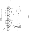
- Figure 1 shows a wireless communication system 10 according to some embodiments.
- the system 10 includes a transmit radio node 12 configured to transmit a reference signal 16 to a receive radio node 14.
- Figure 1 for instance shows the transmit radio node 12 in the form of a radio network node (e.g., a base station) and shows the receive radio node 14 in the form of a wireless device such as a user equipment, e.g., such that the reference signal 16 constitutes a downlink reference signal.
- a radio network node e.g., a base station
- the receive radio node 14 in the form of a wireless device such as a user equipment, e.g., such that the reference signal 16 constitutes a downlink reference signal.
- This reference signal 16 in some embodiments may be a tracking reference signal (TRS) configured for use by the receive radio node 14 for time and/or frequency tracking (e.g., frequency offset estimation).
- TRS tracking reference signal
- the reference signal 16 is transmitted phase coherently such that all symbols of the reference signal 16 are transmitted with the same precoder, i.e., on the same antenna port.
- Figure 1 shows that the reference signal 16 comprises multiple reference symbols 18, e.g., in a certain sequence or series.
- These reference symbols 18 e.g., in the form of Orthogonal Frequency Division Multiplexing, OFDM, symbols
- OFDM Orthogonal Frequency Division Multiplexing
- Figure 1 shows reference symbols 18 received on time resources 20 that are indexed for instance by indices 3, 5, 7, and 14.
- no reference symbol 18 of the reference signal 16 is transmitted or received on any of the other time resources 20 shown in Figure 1 , e.g., as these resources may instead be used for user data, control data, or other types of reference signals.
- Figure 1 shows that the receive radio node 14 receives a first set 22-1 of reference symbols 18 that includes reference symbols 18-1, 18-2, and 18-3, e.g., as received on respective time resources 3, 5, and 7. These reference symbols in the first set 22-1 may for instance have a maximum inter-symbol distance of two symbols as shown.
- Figure 1 also depicts the receive radio node 14 receives a second set 22-2 of reference symbols 18 that includes symbols 18-1, 18-2, 18-3, and 18-4, e.g., as received on respective time resources 3, 5, 7, and 14. In this case, therefore, the first set 22-1 is a subset of the second set 22-2.
- reference symbols in the second set 22-2 may for instance have a maximum inter-symbol distance of seven symbols as shown (i.e., between symbol 18-3 and 18-4). In some embodiments, therefore, the first and second sets 22-1, 22-2 are associated with different spacings, patterns, and/or density of reference symbols 18.
- the receive radio node 14 exploits the first and second sets 22-1, 22-2 of reference symbols 18 to estimate frequency offset, e.g., via an iterative process.
- the receive radio node 14 includes a first estimator 24-1 that determines a first frequency offset estimate 26-1 using the first set 22-1 of reference symbols 18.
- the first estimator 24-1 provides this first frequency offset estimate 26-1 to a second estimator 24-2.
- the second estimator 24-2 determines, based on the first frequency offset estimate 26-1, a second frequency offset estimate 26-6 using the second set 22-2 of reference symbols 18.
- the receive radio node 14 further includes a third estimator 24-3 that determines a third frequency offset estimate 26-3 as a function of (e.g., sum of) the first and second frequency offset estimates 24-1, 24-2.
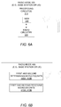
- FIG. 2 correspondingly illustrates a method 200 performed by a receive radio node 14 according to some embodiments.
- the method 100 includes receiving a first set 22-1 of reference symbols of a reference signal 16 during respective time resources (Block 110), and determining a first frequency offset estimate 26-1 using the first set 22-1 of reference symbols (Block 120).
- the method 100 also includes receiving a second set 22-2 of reference symbols of the reference signal 16 during respective time resources (Block 130), and determining, based on the first frequency offset estimate 26-1, a second frequency offset estimate 26-2 using the second set 22-2 of reference symbols (Block 140).
- the method 200 further includes determining a third frequency offset estimate 26-3 as a function of (e.g., sum of) the first and second frequency offset estimates 26-1 and 26-2 (Block 150).
- the method 200 in some embodiments further includes tuning a local oscillator frequency, or performing frequency offset compensation, based on the second frequency offset estimate 26-2 (or the third frequency offset estimate 26-3 if such was determined) (Block 160).
- the first frequency offset estimate 26-1 is used to receive, (at least partially) compensate, or otherwise pre-process the second set 22-2 of reference symbols to reduce the risk that phase ambiguity or aliasing will occur when using the second set 22-2 of reference symbols to determine the second frequency offset estimate 26-2.
- the first set 22-1 of reference symbols is a subset of the second set 22-2. In other embodiments, at least one reference symbol included in the first set is also included in the second set.
- the first and second sets of reference symbols are received using the same local oscillator frequency for down conversion. That is, the receive radio node 14 in some embodiments does not re-tune the local oscillator frequency between determining the first and second estimates. In these and other embodiments, the receive radio node 14 may instead compensate or pre-process the second set 22-2 of reference symbols to resolve, eliminate, or mitigate phase ambiguity or aliasing.
- Figure 3 illustrates some embodiments in this regard.
- the receive radio node 14 calculates the first frequency offset estimate 26-1 using that first set 22-1 of reference symbols in Blocks 220-240.
- the receive radio node 14 determines symbol-to-symbol phase changes over time across the reference symbols in the first set 22-1, with symbol-to-symbol phase changes being within a set of possible phase changes that has a range of 2 ⁇ (Block 220).
- the receive radio node 14 determines, for each reference symbol in the first set 22-1, the phase of that reference symbol within a set of possible phases that has a range greater than 2 ⁇ (e.g., so as to resolve any phase ambiguity) by calculating a partial sum of the symbol-to-symbol phase changes up to the time resource during which that reference symbol was received (Block 230).
- the receive radio node 14 then calculates the first frequency offset estimate 26-1 as a rate at which the determined phases vary over the time resources during which the first set 22-1 of reference symbols are received (Block 240).
- the receive radio node 14 determines the second frequency offset estimate 26-2 based on the first frequency offset estimate 26-1. In particular, after receiving reference symbols in the second set 22-2 (Block 250), the receive radio node 14 3 rotates the reference symbols in the second set 22-2 based on the first frequency offset estimate 26-1 (Block 260). Then, to determine the phase of each reference symbol in the second set 22-2 as rotated, the receive radio node 14 determines symbol-to-symbol phase changes over time across the reference symbols in the second set 22-2 as rotated, with symbol-to-symbol phase changes being within a set of possible phase changes that has a range of 2 ⁇ (Block 270).
- the receive radio node 14 determines, for each reference symbol in the second set 22-2, the phase of that reference symbol within a set of possible phases that has a range greater than 2 ⁇ by calculating a partial sum of the symbol-to-symbol phase changes up to the time resource during which that reference symbol was received (Block 280).
- the receive radio node 14 calculates the second frequency offset estimate 26-2 as a rate at which the determined phases vary over the time resources during which the second set 22-2 of reference symbols are received (Block 290).
- the receive radio node 14 determines the phase of each reference symbol in the second set 22-2 based on the first frequency offset estimate 26-1 by determining symbol-to-symbol phase changes over time across the reference symbols in the second set 22-2, with symbol-to-symbol phase changes being within a set of possible phase changes that has a range of 2 ⁇ and that is calculated based on the first frequency offset estimate 26-1.
- the receive radio node 14 determines, for each reference symbol in the second set 22-2, the phase of that reference symbol within a set of possible phases that has a range greater than 2 ⁇ by calculating a partial sum of the symbol-to-symbol phase changes up to the time resource during which that reference symbol was received.
- the first and second sets 22-1, 22-2 of reference symbols are received using different local oscillator frequencies for down conversion.
- the local oscillator frequency used to receive the second set 22-2 of reference symbols may be based on the first frequency offset estimate 26-1. That is, the receive radio node 14 may adjust the local oscillator frequency used to receive the second set 22-2 of reference symbols, based on the first frequency offset estimate 26-1.
- the time resources 20 on which the reference symbols 18 may be transmitted and received may more specifically include a first set S1 of time resources and a second set S2 of time resources.
- the first and second sets S1, S2 may differ in at least one time resource, e.g., the sets S1, S2 may be mutually exclusive or may partially overlap in terms of one or more time resources.
- With partial overlap of the sets S1, S2, at least one time resource included in the first set S1 may be also included in the second set S2.
- the partial overlap is realized in that the first set S1 is a subset of the second set S2.
- Figure 4 illustrates one example of such embodiments by showing that the time resources 20 on which the reference symbols 18 are received include a first set S1 and a second set S2.
- the first set S1 as shown includes time resources 3, 5, and 7, whereas the second set S2 includes time resources 3, 5, 7, and 14, i.e., the first set S1 is a subset of the second set S2.
- the sets S1, S2 may be associated with different spacings, patterns, and/or densities of time resource in the time domain for carrying reference symbols 18, e.g., such that the reference symbol resource density varies over time.
- the sets S1, S2 in this regard may for instance be associated with different maximum separation distances in the time domain between time resources 20 that carry reference symbols 18.
- the first set S1 includes a first pair of time resources that are separated from one another in time by a first separation distance D1, with no reference symbol of the reference signal 16 on any time resource between the first pair of time resources in the time domain (i.e., the time resources in the first pair occur consecutively in an ordering of those time resources that carry reference symbols 18 in the time domain, ignoring time resources that do not carry such reference symbols 18).
- the second set S2 includes a second pair of time resources that are separated from one another in the time domain by a second separation distance D2, with no reference symbol of the reference signal on any time resource between the second pair of time resources in the time domain.
- the second separation distance D2 is different than the first separation distance D1.
- the second separation distance D2 is at least twice as large as the first separation distance D1. In other embodiments, the second separation distance D2 is at least three times as large as the first separation distance D1. In still other embodiments, the second separation distance D2 is at least five times as large as the first separation distance D1.
- Figure 4 shows that the first set S1 includes time resources 3, 5, and 7 which occur consecutively one after another in the time domain with respect to time resources that carry reference symbols 18 of the reference signal 16, i.e., they are shown as nonconsecutive with respect to all time resources including non-reference-symbol time resources 4 and 6 intervening between them, but consecutive with respect to only time resources 3, 5, 7, and 14 that carry reference symbols of the reference signal 16.
- the first set S1 includes two pairs of consecutive time resources: one pair that includes time resources 3 and 5 and another pair that includes time resources 5 and 7. Each of these pairs do not have any time resource between them that carries a reference symbol of the reference signal 16.
- Figure 1 shows that the second set S2 includes time resources 3, 5, 7, and 14 which occur consecutively one after another in the time domain with respect to time resources that carry reference symbols 18 of the reference signal 16.
- This second set S2 differs in that it includes three pairs of consecutive time resources: one pair that includes time resources 3 and 5, another pair that includes time resources 5 and 7, and yet another pair that includes time resources 7 and 14.
- pairs 3-5 and 5-7 have the first separation distance D1
- the second separation distance D2 is actually more than twice as large as the first separation distance D1.
- the first and second separation distances D1, D2 constituted the maximum separation distance among the pairs of time resources in each respect set S1, S2.
- This maximum separation distance in a sense characterizes or reflects a density of the time resources used for carrying reference symbols 18 of the reference signal 16.
- the first separation distance D1 is a maximum separation distance among the one or more respective separation distances of the one or more pairs included in the first set S1.
- the second separation distance is a maximum separation distance among the one or more respective separation distances of the one or more pairs included in the second set S2.
- the maximum separation distance of the second set S2 may be at least two times, three times, five times, etc. the maximum separation distance of the first set S1.
- the first separation distance D1 is less than or equal to an ambiguity or alias inducing separation distance which when exceeded ambiguity or aliasing in the estimated phases of the reference symbols will or is (more) likely to occur.
- the second separation distance is greater than the ambiguity or aliasing inducing separation distance, in favor of increased estimate accuracy or range.
- the ambiguity or aliasing inducing separation distance may be for instance one half divided by the actual, estimated, worst-case, or assumed error in the local oscillator frequency (Hz) with which the reference symbols on the first set S1 of time resources are or are assumed to be received.
- Hz local oscillator frequency
- the receive radio node 14 may perform frequency tracking using reference symbols received on the first set S1 of time resources in order to obtain a first frequency offset estimate that is immune or less susceptible to error due to aliasing or phase ambiguity at the local oscillator frequency. The receive radio node 14 may then use the reference symbols received on the second set S2 of time resources in conjunction with the first frequency offset estimate in order to obtain a second frequency offset estimate that has greater possible accuracy or range than the first estimate.
- radio resources on which the reference signal 16 is transmitted or received occur in periodically recurring bursts, e.g., such that the reference signal 16 is effectively transmitted or received in periodically recurring bursts.
- Figure 4 illustrates just one of multiple periodically recurring bursts.
- Figure 5 illustrates the periodicity with which the bursts occur according to one example.
- Four reference symbols 18 are included in each burst 30, e.g., as shown in Figure 4 such that reference symbols 18 are transmitted or received on symbols 3, 5, 7, and 14 of each burst 30.
- the bursts 30 periodically recur with a periodicity Y (e.g., every Y slots). No reference symbols 18 of the reference signal 16 are transmitted between successive bursts 30.
- the first set S1 and second set S2 of radio resources on which reference symbols 18 are transmitted or received are included in the same burst 30.
- each of the reference symbol radio resources included in the first set S1 is included in the same burst 30 as the burst within which are included each of the reference symbol radio resources included in the second set S2.
- any given burst 30 includes each reference symbol radio resource in the first set S1 as well as each reference symbol radio resource in the second set S2.
- Figure 5 for example shows that each of the reference symbol radio resources in first set S1 is included in burst 30-1 and each of the reference symbol radio resources in the second set S2 is also included in that same burst 30-1.
- the first set S1 occurs before the second set S2 in the same burst.
- the same may be said for burst 30-N; that is, each reference symbol radio resource in first set S1 is included in burst 30-N and each reference symbol radio resource in the second set S2 is also included in that same burst 30-N.
- any given burst 30 itself provides different spacings, patterns, and/or densities of radio resource for carrying reference symbols 18, e.g., such that the reference symbol radio resource density varies within any given burst 30.
- any given burst 30 includes some reference symbol radio resources (e.g., in S1) that are separated by less than the ambiguity or alias inducing separation distance as well as some reference symbol radio resources (e.g., in S2) that are separated by greater than or equal to the ambiguity or alias inducing separation distance.
- the receive radio node 14 may thereby exploit both separation distances within any given burst 30 for performing frequency offset estimation.
- Figure 5 showed a burst 30 as spanning only a single time slot 32, a burst 30 in other embodiments may span multiple consecutive time slots 32. Even with a burst 30 spanning multiple time slots 32, the first and second sets S1, S2 may nonetheless still be included in the same burst 30 in some embodiments.
- the first and second sets S1, S2 may be included in different bursts.
- the first and second sets S1, S2 are mutually exclusive, the first set S1 may be included only in one burst and the second set S2 may be included only in another burst. That is, all reference symbol radio resources in the first set S1 may be included in one burst whereas all reference symbol radio resources in the second set S2 may be included in a different bust.
- the receive radio node 14 in this case may exploit different separation distances within different respective bursts for performing frequency offset estimation.
- first and second sets of reference symbols that differ in at least one reference symbol
- other embodiments herein apply where the first and second sets are the same. That is, the embodiments iteratively determine successive frequency offset estimates using the same set of reference symbols.
- some embodiments re-tune the oscillator frequency between the first and second estimates.
- the re-tuning reduces error in the frequency offset of the receiver so as to mitigate or lessen the risk of phase ambiguity or aliasing that would otherwise affect the second frequency offset estimate.
- a radio node herein is any type of node capable of communicating over radio signals.
- a radio network node herein is any type of network node (e.g., a base station) capable of communicating with another node over radio signals.
- a wireless device is any type device capable of communicating with a radio network node or another wireless device over radio signals.
- a wireless device may therefore refer to a machine-to-machine (M2M) device, a machine-type communications (MTC) device, a NB-loT device, etc.
- M2M machine-to-machine
- MTC machine-type communications
- a wireless device may also be referred to as a radio device, a radio communication device, a wireless terminal, or simply a terminal - unless the context indicates otherwise, the use of any of these terms is intended to include device-to-device devices, machine-type devices or devices capable of machine-to-machine communication, sensors equipped with a wireless device, wireless-enabled table computers, mobile terminals, smart phones, laptop-embedded equipped (LEE), laptop-mounted equipment (LME), USB dongles, wireless customer-premises equipment (CPE), etc. It should be understood that these devices may be user equipments, but are generally configured to transmit and/or receive data without direct human interaction.
- a wireless device as described herein may be, or may be comprised in, a machine or device that performs monitoring or measurements, and transmits the results of such monitoring measurements to another device or a network.
- machines are power meters, industrial machinery, or home or personal appliances, e.g. refrigerators, televisions, personal wearables such as watches etc.
- a wireless device as described herein may be comprised in a vehicle and may perform monitoring and/or reporting of the vehicle's operational status or other functions associated with the vehicle.
- separation distance refers to a distance separating radio resources on which reference symbols are transmitted or received. Separation distance may thus correspond to inter symbol distance.
- a radio node e.g., a receive radio node 14
- the radio node comprises respective circuits configured to perform the steps shown in Figure 2 and/or 3.
- the circuits in this regard may comprise circuits dedicated to performing certain functional processing and/or one or more microprocessors in conjunction with memory.
- memory which may comprise one or several types of memory such as read-only memory (ROM), random-access memory, cache memory, flash memory devices, optical storage devices, etc.
- the memory stores program code that, when executed by the one or more microprocessors, carries out the techniques described herein.
- FIG 6A illustrates additional details of a radio node 300 in accordance with one or more embodiments.
- the radio node 300 includes one or more processing circuits 310 and radio circuitry 320.
- the radio circuitry 320 may be configured to transmit and/or receive via one or more antennas that are internal and/or external to the radio node 300.
- the one or more processing circuits 310 are configured to perform processing described above, e.g., in Figure 2 and/or 3, such as by executing instructions stored in memory 330.
- the one or more processing circuits 310 in this regard may implement certain functional means or units.
- Figure 6B in this regard illustrates additional details of a radio node 400 in accordance with one or more other embodiments.
- the radio node 400 may include first and second receiving modules or units 410A, 410B for receiving the first and second sets of reference symbols in Blocks 110 and 130 of Figure 2 .
- the radio node 400 may further include first and second determining modules or units 420A, 420B for determining the first and second frequency offset estimates in Blocks 120 and 140 of Figure 2 .
- One or more of these modules or units may be implemented by the one or more processing circuits 310 in Figure 6A .
- a computer program comprises instructions which, when executed on at least one processor of a radio node, cause the radio node to carry out any of the respective processing described above.
- a computer program in this regard may comprise one or more code modules corresponding to the means or units described above.
- Embodiments further include a carrier containing such a computer program.
- This carrier may comprise one of an electronic signal, optical signal, radio signal, or computer readable storage medium.
- the reference signal 16 may be configured for or usable in a 5G or New Radio (NR) wireless communication system.
- NR New Radio
- NR new 'fifth generation' radio access technology
- 3GPP 3rd Generation Partnership Project
- One important aspect of this technology is to avoid "always-on" signals, i.e. reference signals transmitted in every subframe, as far as possible. This is in order to avoid creating unnecessary interference, reduce energy consumption and also to make it easier in the future to introduce new technology modes unrestricted by the existence of always-on signals that need to be kept for backwards-compatibility reasons.
- LTE Long Term Evolution
- CRS cell reference signals
- the CRS is utilized for multiple purposes including measurements, frequency offset estimation and time synchronization as well as being used for demodulation of physical downlink channels. Even though the intention is to avoid specifying mandatory transmission of always-on signals like CRSs in NR, the critical functionalities of time synchronization and frequency offset estimation must be supported.
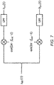
- b t b 0 t ⁇ e ⁇ i ⁇ 2 ⁇ ⁇ f err ⁇ t
- b 0 ( t ) is the equivalent baseband signal resulting from down conversion with the true received frequency ⁇ c
- ⁇ est ⁇ c
- the equivalent baseband signal b ( t ) b 0 ( t ) ⁇ I(t) + i ⁇ Q ( t ).
- the equivalent baseband signal b ( t ) b 0 ( t ) ⁇ e -i ⁇ 2 ⁇ err ⁇ t .
- Orthogonal Frequency Division Multiplexing a discrete Fourier transform is performed (typically using a Fast Fourier Transform, FFT, algorithm) of the time-sampled baseband signal for each OFDM symbol.
- FFT Fast Fourier Transform
- the error in the frequency estimate will result in: (i) a phase difference between the OFDM symbols (a factor e -i ⁇ 2 ⁇ ⁇ ⁇ err ⁇ t n + i ⁇ where t n is the time of the start of the n'th OFDM symbol); and (ii) a mixing of the Fourier coefficients as compared with the Fourier coefficents resulting from down conversion with the true received frequency. This may be viewed as inter-subcarrier interference.
- Frequency estimation may be performed based on estimating how fast the phase changes in the equivalent baseband signal resulting from down conversion with the current best estimate of the frequency. If the estimate is based on known reference signals with large separation in time, then the phase difference to estimate will be large and a larger phase in comparison to noise will improve accuracy. A large separation in time between consecutive reference signals increases the risk for aliasing however.
- the instantaneous phase is only defined up to 2 ⁇ ⁇ and thus the phase difference between two consecutive reference signals becomes ambiguous if f err ⁇ ⁇ t > 1 2 , where ⁇ t is in seconds and where
- the ambiguity or aliasing inducing separation distance may be equal to 1 2 f err .
- the reference signal used for frequency estimation is transmitted repeatedly over a long time span with a time difference between consecutive signals that is smaller than 1 2 ⁇ f err .
- a UE in NR may get a first rough frequency estimate based on a synchronization block sent with a certain frequency, say every 20ms or 40ms. This will give a frequency estimate with an accuracy of say 5% of the subcarrier spacing (the design of the synchronization block is not yet settled and UE requirements are not set). This is far from sufficient for high performance reception and additional reference signals are needed for frequency estimation. In NR this reference signal will most likely be used for multiple purposes such as e.g. time tracking, delay spread estimation and Doppler spread estimation.
- an irregular, or variable, temporal pattern is used for the transmission and reception of reference signals that are used for frequency estimation.
- the temporal pattern is such that there is a subset (call it G) of reference signals that are transmitted spaced closely in time (e.g. closely spaced OFDM symbols) while in general these reference signals are transmitted more sparsely spaced in time.
- the maximum time between consecutive signals in the subset G of reference signals should be such that aliasing is unlikely to occur based on the initial frequency estimate.
- the maximum time between consecutive signals in the set of all reference signals on the other hand can be allowed to be so large that aliasing is likely to occur based on the initial frequency estimate but should be small enough for aliasing to be avoidable with the help of a frequency estimate based on the subset G of reference signals.
- the frequency is estimated in two steps according to some embodiments. First, the frequency is estimated based on the subset G of the reference signals. Next, the frequency is estimated based on the full set of reference signals making use of the frequency estimate in the first step to avoid aliasing.
- Some embodiments therefore include a tracking reference signal (TRS) burst pattern consisting of a sub-pattern that is dense in time and thus robust towards aliasing given an initial frequency estimate.
- TRS tracking reference signal
- a method in a wireless communication network comprises transmitting reference signals to perform frequency offset estimation, where the reference signals are transmitted in bursts and where a burst contains a set S of reference signal symbols and is further divided into a subset G of the set S of reference signal symbols, having a maximum symbol spacing smaller than the maximum symbol spacing of the set S.
- a method in a wireless terminal comprises receiving (measuring on) reference signals to perform frequency offset estimation, where the reference signals are received in bursts and where a burst contains a set S of reference signal symbols and is further divided into a subset G of the set S of reference signal symbols, having a maximum symbol spacing smaller than the maximum symbol spacing of the set S.
- the wireless terminal may be configured in this way by default, or by radio resource control (RRC), or by RRC in combination with downlink control information (DCI).
- RRC radio resource control
- DCI downlink control information
- a method in a wireless terminal comprises resolving phase ambiguity using the subset of G reference signal symbols, where the maximum symbol spacing of the subset G is smaller than the maximum reference signal symbol spacing of the set S.
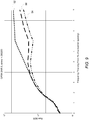
- FIG. 8 shows frequency offset estimation error RMS as a function of the frequency offset. This is shown as line 40 for one step estimation based on TRS in symbol 3, 5, 7 and 9, line 42 for one step estimation based on TRS in symbol 3, 5, 7 and 14, and line 44 for two step estimation based on TRS in symbol 3, 5, 7 and 14 using symbol 3, 5, and 7 in the first-step estimation and symbol 3, 5, 7 and 14 in the second-step estimation.
- Figure 9 shows raw bit error rate (BER) as a function of the initial frequency offset after re-tuning the receiver oscillator based on the frequency estimation.
- Line 50 shows raw BER for one step frequency estimation based on TRS in symbol 3, 5, 7 and 9.
- Line 52 shows raw BER for one step frequency estimation based on TRS in symbol 3, 5, 7 and 14.
- line 54 shows raw BER for two step frequency estimation based on TRS in symbol 3, 5, 7 and 14 using symbol 3, 5, and 7 in the first step estimation and symbol 3, 5, 7 and 14 in the second step estimation.
- TRS Tracking Reference Signal
- the TRS is defined as a burst of S OFDM symbols with a certain symbol spacing between OFDM symbols having TRS.
- Each TRS burst has a total time extent of T OFDM symbols and may span one or multiple slots.
- the TRS resource elements (RE) in each symbol used to carry the TRS In the case of an OFDM based system a subset of the subcarriers is used for the TRS resource elements (RE) in each symbol used to carry the TRS.
- RE resource elements
- One example of mapping in the frequency domain is when the subcarriers used for TRS in an OFDM symbol are equally spaced across the transmission bandwidth, also known as a comb based structure.
- the transmission bandwidth of the TRS may be smaller than the system bandwidth. For example, the TRS in some embodiments spans only 10 MHz while the system bandwidth is 80 MHz.
- the TRS burst can be configured to be sent periodically with some periodicity, for example starting every Y:th slot.
- Each TRS burst has a length of X slots.
- a set S of OFDM symbols are used to carry the TRS, denoted as the S "TRS symbols" below.
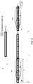
- FIG. 10 shows one such pattern 60-1 for the mapping of a TRS burst onto OFDM symbols.
- OFDM symbols 66 carrying the TRS include symbols 1, 5, 8, and 12 of each of the three slots 62 in the TRS burst.
- the other OFDM symbols in three slots are OFDM symbols 64 that do not carry TRS.
- PDCCH physical downlink control channel
- PDSCH physical downlink shared channel
- CSI-RS channel state information reference signal
- Some embodiments introduce a time-variable TRS density in order to reduce the overhead and unnecessary interference. Some embodiments focus on time density and related frequency offset estimation, but the same principle holds for frequency density and time synchronization.
- the variable time density occurs within a TRS burst.
- the TRS symbol density is higher in one part (e.g. the beginning) of the TRS burst but sparser in another part (e.g. the end) of the TRS burst.
- the TRS burst is constructed so that there is a subset G of the set S of TRS symbols that are used to carry the TRS for which the maximum time between consecutive TRS symbols is significantly smaller than the maximum time between consecutive TRS symbols in the full set S.
- the time density can also be controlled on a slot basis, in case a TRS burst uses multiple adjacent slots.
- the first slot in the TRS burst has high TRS density, e.g. with OFDM symbol spacing 2 between consecutive TRS symbols, while the following slots in the TRS burst have lower TRS density, e.g. with OFDM symbol spacing 4 between consecutive TRS symbols.
- the UE can make accurate frequency offset estimation based on the first slot in the TRS burst and then make further adjustments on the TRS symbols in the remaining slots in the TRS burst.
- the benefit of this approach is that each slot has a single TRS symbol time density and density changes at the slot boundary only, which simplifies PDSCH to resource element (RE) mapping.
- RE resource element
- Figure 10 shows a more concrete example in the form of a pattern 60-2.
- symbol numbers 4, 9, 14 and 32 carry the TRS burst.
- Figure 10 shows yet another example in the form of a pattern 60-3.
- symbol numbers 3, 5, 7 and 14 carry the TRS burst.
- variable time density occurs between TRS bursts.
- some TRS bursts have higher time density between TRS symbols in the TRS burst than other TRS bursts.
- the periodicity of TRS bursts is Y slots and every N:th burst has high time density (OFDM symbols carrying TRS symbol is dense) while the in-between N-1 bursts have low time density (including the case that this low density TRS burst only has a single OFDM symbol containing TRS symbol, to allow for mainly time synchronization).
- the TRS bursts transmitted in-between may thus have different time durations with respect to every N:th TRS burst.
- a TRS configuration comprising the TRS burst parameters and its periodicity (Y), may be fixed in standard (e.g., 3GPP) specifications or configured using higher layer signaling such as RRC signaling.
- a UE may also have multiple, different TRS's configured for different purposes. For example, the UE may have one default TRS burst, given by specification, that gives the frequency offset estimate accuracy (and time synchronization) sufficient to demodulate system information and to perform RRC configuration.
- the UE may also have a second TRS burst, which is UE specifically configured by RRC, to obtain a more accurate time frequency tracking performance necessary for higher order modulation (e.g. 256 QAM) and multiple input multiple output (MIMO). Note that the UE still needs to know the presence of the default TRS even though the second TRS is configured, in order to know which REs are available for PDSCH and which are occupied by a TRS transmission.
- MIMO multiple input multiple output
- the presence of TRS symbols in a slot and/or the TRS density is dynamically signaled by downlink control information (DCI) in a control channel in a slot, which may be a broadcast control channel message, such as the group common PDCCH (GC-PDCCH) in the beginning of the slot.
- DCI downlink control information
- a control channel in a slot which may be a broadcast control channel message, such as the group common PDCCH (GC-PDCCH) in the beginning of the slot.
- GC-PDCCH group common PDCCH
- Another use case of the dynamic signaling is to indicate whether the TRS burst has full density (e.g. regular time density/equal spacing across the whole TRS burst) or reduced density (e.g. according to embodiments described above with irregular density across the TRS burst to reduce overhead).
- the dynamic signaling allows the network to use the full density in case no UE is scheduled (no PDSCH transmission) as this will not cause any overhead or use the reduced density in case of a UE is scheduled in resources that overlaps with (parts of) the TRS burst.
- a slot contains multiple configured TRS's mapped to orthogonal resources (resource elements).
- One use case of multiple TRS is a default TRS and one UE specifically configured TRS as discussed earlier, or another use case is transmission from multiple transmission points or multiple antenna panels which may not have the same local oscillator reference, hence one TRS is needed for each such reference.
- control channel such as GC-PDCCH contains an indication (such as an index of set of indices) of which TRS burst or TRS bursts is/are present in the slot and/or which TRS density is used (full or reduced).
- the burst configuration of the TRS depends on whether the UE is in active-mode or in discontinuous reception (DRX) DRX mode.
- DRX discontinuous reception
- the UE can be scheduled with a TRS burst configuration that can both handle relatively large frequency errors and provide accurate estimates.
- estimation of the frequency offset at the receiver is performed in the following way:
- FIG 11 shows the preparatory steps 1 and 2, where the application of a discrete Fourier transform (DFT) is performed typically as a FFT.
- DFT discrete Fourier transform
- Step 4 can be performed in many different but mathematically similar or even equivalent ways. Three embodiments are described below, e.g., where embodiments 1 and 3 implement Block 260 of Figure 3 .
- Embodiment 1 for implementing Step 4 entails rotating the received reference signal's Fourier coefficients with a phase by multiplying with e i ⁇ 2 ⁇ ⁇ ⁇ 1 ⁇ ( t - t 0 ) where t is the time of the start of the OFDM symbol (not the start of the cyclic prefix, CP) and t 0 is an arbitrary reference time.
- the third and final estimate of the frequency offset in this case is calculated as ⁇ 1 + ⁇ 2 .
- the receiver calculates the phase difference ⁇ ⁇ calc between the two symbols based on the received signals resolving the 2 ⁇ ambiguity by selecting the phase ⁇ ⁇ calc in the interval ( ⁇ ⁇ est - ⁇ , ⁇ ⁇ est + ⁇ ]. The receiver does this for all pairs of consecutive TRS symbols. Partial cumulative sums of ⁇ ⁇ calc now give global phase information for all TRS symbols.
- Embodiment 3 for implementing Step 4 entails rotating the equivalent base band time domain samples by multiplying time sample n with e i ⁇ 2 ⁇ ⁇ ⁇ 1 ⁇ tn where t n is the time of time sample n.
- the receiver re-does the OFDM demodulation (FFT) based on the rotated time samples.
- FFT OFDM demodulation
- G ⁇ s i
- i 1,2,3,... P ⁇ of TRS symbols.
- the maximum time difference between consecutive signals in the full set of TRS signals is however larger making aliasing more likely (aliasing becomes likely around 1 2 ⁇ f acc where f acc is a measure of the accuracy of the frequency estimate).
- This step corresponds to Block 220 of Figure 3 .
- the range of the global phase is not bound to the interval (- ⁇ , ⁇ ], i.e., it has a range greater than 2 ⁇ . This step corresponds to Block 230 of Figure 3 .
- the receiver calculates the first frequency offset estimate ⁇ 1 as the average of ⁇ 1 k over the subcarrier c k . This step corresponds to Block 240 of Figure 3 .
- the range of the global phase is not bound to the interval (- ⁇ , ⁇ ], i.e., it has a range greater than 2 ⁇ . This corresponds to Block 280 of Figure 3 .
- the receiver calculates the second frequency offset estimate ⁇ 2 as the average of ⁇ 2 k over the subcarrier c k . This corresponds to Block 290 of Figure 3 .
- the receiver then calculates the final frequency offset estimate as ⁇ 1 + ⁇ 2 .
- This "final" frequency offset estimate may correspond to the "third" frequency offset estimate described with respect to Figure 1 .
- Embodiments herein may be generalized to multiple step estimation.
- each estimation is based on a new subset of the full set of TRS signals, where the maximum time between consecutive TRS signals in a given subset would be larger than for the subset used for the previous estimation.
- the TRS signal is designed so that aliasing is unlikely over the maximum time between consecutive TRS signals in a given subset, when the frequency estimate from the previous frequency estimation is used to resolve phase ambiguities.
- the first estimate is relative to the frequency used in the down conversion.
- the frequency used for the down conversion may be based on a frequency estimate done on a synchronization signal (SS) block or (e.g. in the case that SS block is not transmitted from the same point or by the same transmitter as the TRS and the data) it can be based on the accuracy of the oscillator in the UE or it can be based on a previous estimate based on the TRS.
- SS synchronization signal
Landscapes
- Engineering & Computer Science (AREA)
- Signal Processing (AREA)
- Computer Networks & Wireless Communication (AREA)
- Mobile Radio Communication Systems (AREA)
Claims (13)
- Procédé mis en œuvre par un nœud radio (14) pour une estimation de décalage de fréquence, le procédé comprenant :la réception (110) d'un premier ensemble (22-1) de symboles de référence d'un signal de référence (16) pendant des ressources temporelles respectives ;la détermination (120) d'une première estimation de décalage de fréquence (26-1) en utilisant le premier ensemble (22-1) de symboles de référence ;la réception (130) d'un deuxième ensemble (22-2) de symboles de référence du signal de référence pendant des ressources temporelles respectives, dans lequel le premier ensemble (22-1) de symboles de référence est un sous-ensemble du deuxième ensemble (22-2) de symboles de référence ;caractérisé par :la détermination de changements de phase de symbole à symbole au fil du temps à travers les symboles de référence dans le deuxième ensemble (22-2), des changements de phase de symbole à symbole étant au sein d'un ensemble de changements de phase possibles qui a une plage de 2n et qui est calculé sur la base de la première estimation de décalage de fréquence (26-1) ; etla détermination, pour chaque symbole de référence dans le deuxième ensemble (22-2), de la phase de ce symbole de référence au sein d'un ensemble de phases possibles qui a une plage supérieure à 2n en calculant une somme partielle des changements de phase de symbole à symbole jusqu'à la ressource temporelle pendant laquelle ce symbole de référence a été reçu ; etla détermination d'une deuxième estimation de décalage de fréquence (26-2) sur la base des phases déterminées.
- Procédé selon la revendication 1, dans lequel les premier et deuxième ensembles de symboles de référence sont reçus en utilisant la même fréquence d'oscillateur local pour une conversion descendante.
- Procédé selon l'une quelconque des revendications 1 ou 2, dans lequel la détermination de la première estimation de décalage de fréquence (26-1) comprend la détermination d'une phase de chaque symbole de référence dans le premier ensemble (22-1) au sein d'une plage de phase supérieure à 2n et le calcul de la première estimation de décalage de fréquence (26-1) en tant qu'un taux auquel les phases déterminées varient sur les ressources temporelles pendant lesquelles le premier ensemble (22-1) de symboles de référence sont reçus.
- Procédé selon la revendication 3, dans lequel la détermination de la phase de chaque symbole de référence dans le premier ensemble (22-1) comprend :la détermination de changements de phase de symbole à symbole au fil du temps à travers les symboles de référence dans le premier ensemble (22-1), des changements de phase de symbole à symbole étant au sein d'un ensemble de changements de phase possibles qui a une plage de 2n ; etla détermination, pour chaque symbole de référence dans le premier ensemble (22-1), de la phase de ce symbole de référence au sein d'un ensemble de phases possibles qui a une plage supérieure à 2n en calculant une somme partielle des changements de phase de symbole à symbole jusqu'à la ressource temporelle pendant laquelle ce symbole de référence a été reçu.
- Procédé selon l'une quelconque des revendications 1 à 4, comprenant en outre :la détermination d'une troisième estimation de décalage de fréquence en tant que somme des première et deuxième estimations de décalage de fréquence ; etla syntonisation d'une fréquence d'oscillateur local, ou la mise en œuvre d'une compensation de décalage de fréquence, sur la base de la troisième estimation de décalage de fréquence.
- Procédé selon la revendication 1, dans lequel les premier et deuxième ensembles de symboles de référence sont reçus en utilisant des fréquences d'oscillateur local différentes pour une conversion descendante, la fréquence d'oscillateur local utilisée pour recevoir le deuxième ensemble (22-2) de symboles de référence étant basée sur la première estimation de décalage de fréquence (26-1).
- Procédé selon l'une quelconque des revendications 1 à 6, dans lequel le premier ensemble (22-1) de symboles de référence sont reçus pendant des ressources temporelles respectives dans un premier ensemble de ressources temporelles, dans lequel le deuxième ensemble (22-2) de symboles de référence sont reçus pendant des ressources temporelles respectives dans un deuxième ensemble de ressources temporelles, dans lequel le premier ensemble de ressources temporelles inclut une première paire de ressources temporelles qui sont séparées les unes des autres dans le temps par une première distance de séparation, sans aucun symbole de référence du signal de référence sur n'importe quelle ressource temporelle entre la première paire de ressources temporelles, et dans lequel le deuxième ensemble de ressources temporelles inclut une deuxième paire de ressources temporelles qui sont séparées les unes des autres dans le temps par une deuxième distance de séparation, sans aucun symbole de référence du signal de référence sur n'importe quelle ressource radio entre la deuxième paire de ressources temporelles, dans lequel la deuxième distance de séparation est au moins deux fois plus grande que la première distance de séparation.
- Procédé selon l'une quelconque des revendications 1 à 7, dans lequel des ressources temporelles sur lesquelles le signal de référence est reçu se produisent dans des salves à récurrence périodique, dans lequel les premier et deuxième ensembles de symboles de référence sont reçus dans la même salve.
- Procédé selon la revendication 8, dans lequel le premier ensemble (22-1) de symboles de référence se produit avant le deuxième ensemble (22-2) de symboles de référence dans la même salve.
- Procédé selon l'une quelconque des revendications 8 ou 9, dans lequel des transmissions sont mises en œuvre dans le système de communication sans fil selon une structure de créneau de temps dans laquelle chacun des multiples créneaux de temps inclut de multiples ressources temporelles, dans lequel une salve couvre de multiples créneaux de temps consécutifs.
- Nœud radio (14, 300, 400) configuré pour utilisation dans un système de communication sans fil, le nœud radio configuré pour :recevoir un premier ensemble (22-1) de symboles de référence d'un signal de référence pendant des ressources temporelles respectives ;déterminer une première estimation de décalage de fréquence (26-1) en utilisant le premier ensemble (22-1) de symboles de référence ;recevoir un deuxième ensemble (22-2) de symboles de référence du signal de référence pendant des ressources temporelles respectives, dans lequel le premier ensemble (22-1) de symboles de référence est un sous-ensemble du deuxième ensemble (22-2) de symboles de référence ;caractérisé en ce que le nœud radio est configuré pour :déterminer des changements de phase de symbole à symbole au fil du temps à travers les symboles de référence dans le deuxième ensemble (22-2), des changements de phase de symbole à symbole étant au sein d'un ensemble de changements de phase possibles qui a une plage de 2n et qui est calculé sur la base de la première estimation de décalage de fréquence (26-1) ; etdéterminer, pour chaque symbole de référence dans le deuxième ensemble (22-2), la phase de ce symbole de référence au sein d'un ensemble de phases possibles qui a une plage supérieure à 2n en calculant une somme partielle des changements de phase de symbole à symbole jusqu'à la ressource temporelle pendant laquelle ce symbole de référence a été reçu ;déterminer une deuxième estimation de décalage de fréquence (26-2) sur la base des phases déterminées.
- Nœud radio selon la revendication 11, configuré pour mettre en œuvre le procédé de l'une quelconque des revendications 2 à 10.
- Programme informatique comprenant des instructions qui, lorsqu'il est exécuté par au moins un processeur d'un nœud radio (14, 300, 400), amène le nœud radio (14, 300, 400) à effectuer le procédé de l'une quelconque des revendications 1 à 10.
Applications Claiming Priority (2)
| Application Number | Priority Date | Filing Date | Title |
|---|---|---|---|
| US201762521367P | 2017-06-16 | 2017-06-16 | |
| PCT/EP2018/065954 WO2018229255A1 (fr) | 2017-06-16 | 2018-06-15 | Estimation de décalage de fréquence |
Publications (2)
| Publication Number | Publication Date |
|---|---|
| EP3639444A1 EP3639444A1 (fr) | 2020-04-22 |
| EP3639444B1 true EP3639444B1 (fr) | 2021-08-04 |
Family
ID=62636218
Family Applications (1)
| Application Number | Title | Priority Date | Filing Date |
|---|---|---|---|
| EP18732051.0A Active EP3639444B1 (fr) | 2017-06-16 | 2018-06-15 | Estimation de décalage de fréquence |
Country Status (3)
| Country | Link |
|---|---|
| US (1) | US11133964B2 (fr) |
| EP (1) | EP3639444B1 (fr) |
| WO (1) | WO2018229255A1 (fr) |
Families Citing this family (5)
| Publication number | Priority date | Publication date | Assignee | Title |
|---|---|---|---|---|
| WO2019047945A1 (fr) | 2017-09-11 | 2019-03-14 | Intel IP Corporation | Procédé et appareil de configuration de signal de référence |
| US11405254B2 (en) * | 2020-11-12 | 2022-08-02 | Rurisond, Inc. | Spread OFDM for radio frequency communications |
| US11665564B2 (en) | 2021-02-08 | 2023-05-30 | Rurisond, Inc. | System and method for generation of shared signal frequency map for frequency sharing choice |
| CN112995074B (zh) * | 2021-05-21 | 2021-08-03 | 展讯通信(天津)有限公司 | 基于trs的afc估计方法、装置、终端和存储介质 |
| CN115102817B (zh) * | 2022-08-24 | 2022-12-13 | 鹏城实验室 | 一种相位跳变修正方法及相关设备 |
Family Cites Families (11)
| Publication number | Priority date | Publication date | Assignee | Title |
|---|---|---|---|---|
| US20040202234A1 (en) | 2003-04-11 | 2004-10-14 | Agency For Science, Technology And Research | Low-complexity and fast frequency offset estimation for OFDM signals |
| US7751503B2 (en) | 2006-04-27 | 2010-07-06 | Jennic Limited | Method for acquiring timing and carrier synchronization of offset-QPSK modulated signals |
| EP2182690B1 (fr) | 2008-11-03 | 2011-08-03 | Telefonaktiebolaget LM Ericsson (publ) | Estimation d'un décalage de fréquence |
| WO2012036605A1 (fr) * | 2010-09-17 | 2012-03-22 | Telefonaktiebolaget Lm Ericsson | Nœud récepteur et procédé mis en œuvre dans ce nœud pour compenser un décalage de fréquence |
| WO2013006104A1 (fr) * | 2011-07-06 | 2013-01-10 | Telefonaktiebolaget L M Ericsson (Publ) | Commande de puissance de transmission de liaison montante et de liaison descendante durant une commutation asynchrone d'états de commande par un équipement utilisateur |
| US9107213B2 (en) | 2011-11-09 | 2015-08-11 | Samsung Electronics Co., Ltd. | Reference signal for time and/or frequency tracking in a wireless network |
| US9094906B2 (en) * | 2011-11-11 | 2015-07-28 | Telefonaktiebolaget Lm Ericsson (Publ) | Multi-stage timing and frequency synchronization |
| US9071327B2 (en) | 2012-11-27 | 2015-06-30 | Gilat Satellite Networks Ltd. | Efficient frequency estimation |
| CN105828413B (zh) | 2015-01-09 | 2020-11-10 | 中兴通讯股份有限公司 | 一种d2d模式b发现的安全方法、终端和系统 |
| US10728758B2 (en) | 2015-01-16 | 2020-07-28 | Samsung Electronics Co., Ltd. | Method of secured transmission and reception of discovery message in a D2D communication system |
| US10728937B2 (en) | 2017-01-09 | 2020-07-28 | Apple Inc. | Synchronization and master information block for off grid radio service |
-
2018
- 2018-06-15 EP EP18732051.0A patent/EP3639444B1/fr active Active
- 2018-06-15 US US16/622,493 patent/US11133964B2/en active Active
- 2018-06-15 WO PCT/EP2018/065954 patent/WO2018229255A1/fr not_active Ceased
Also Published As
| Publication number | Publication date |
|---|---|
| US11133964B2 (en) | 2021-09-28 |
| US20210051048A1 (en) | 2021-02-18 |
| WO2018229255A1 (fr) | 2018-12-20 |
| EP3639444A1 (fr) | 2020-04-22 |
Similar Documents
| Publication | Publication Date | Title |
|---|---|---|
| EP3639443B1 (fr) | Émission ou réception d'un signal de référence dans un système de communication sans fil | |
| EP3639444B1 (fr) | Estimation de décalage de fréquence | |
| US9106276B2 (en) | Method and apparatus for reference signal transmission and reception | |
| US10104630B2 (en) | Methods and devices for time and frequency offset estimation | |
| US9246714B2 (en) | Receiver with cyclic prefix determination | |
| US20120281629A1 (en) | Method and Device for Detecting Primary Synchronization Signal and Generating Sequence in Long Term Evolution (LTE) System | |
| US9185571B2 (en) | Employing reference signals in communications | |
| US11695606B2 (en) | Processing device for a network access node for generating phase compensated modulation symbols | |
| WO2016033978A1 (fr) | Procédé et dispositif d'attribution et de détermination de quasi-colocation | |
| US11678245B2 (en) | User equipment (UE) requested enablement for L1/L2 inter-cell mobility | |
| US11243291B2 (en) | Method for performing OTDOA-related operation by terminal in wireless communication system, and apparatus therefor | |
| EP3229523A1 (fr) | Procédé de réduction d'interférence de liaison montante, et station de base | |
| KR20180061239A (ko) | 브로드캐스트 채널 기반의 주파수 오프셋 추정 | |
| US11558222B2 (en) | Method and receiver device for channel estimation of broadcast channel | |
| CN117813792A (zh) | 用于多个分量载波(cc)上相位噪声(pn)减轻的单个cc上pn减轻导频分配 | |
| US20180131488A1 (en) | Method for transmitting and receiving reference signal | |
| WO2019034252A1 (fr) | Techniques de détermination de la localisation d'un dispositif mobile | |
| CN117676794A (zh) | 估计上行定时提前量的方法、网络设备、装置及存储介质 | |
| Magani et al. | Cell-search and tracking of residual time and frequency offsets in low power NB-IoT devices | |
| Zhao et al. | A frequency offset estimation/tracking algorithm based on trs for 5g nr | |
| CN102223335A (zh) | 一种时偏估计方法和装置 | |
| US20200344027A1 (en) | Network access node, client device and methods for initial access in new radio | |
| WO2011026524A1 (fr) | Estimation de décalage de fréquence ou de temps dans un récepteur multiporteuse |
Legal Events
| Date | Code | Title | Description |
|---|---|---|---|
| STAA | Information on the status of an ep patent application or granted ep patent |
Free format text: STATUS: UNKNOWN |
|
| STAA | Information on the status of an ep patent application or granted ep patent |
Free format text: STATUS: THE INTERNATIONAL PUBLICATION HAS BEEN MADE |
|
| PUAI | Public reference made under article 153(3) epc to a published international application that has entered the european phase |
Free format text: ORIGINAL CODE: 0009012 |
|
| STAA | Information on the status of an ep patent application or granted ep patent |
Free format text: STATUS: REQUEST FOR EXAMINATION WAS MADE |
|
| 17P | Request for examination filed |
Effective date: 20200115 |
|
| AK | Designated contracting states |
Kind code of ref document: A1 Designated state(s): AL AT BE BG CH CY CZ DE DK EE ES FI FR GB GR HR HU IE IS IT LI LT LU LV MC MK MT NL NO PL PT RO RS SE SI SK SM TR |
|
| AX | Request for extension of the european patent |
Extension state: BA ME |
|
| DAV | Request for validation of the european patent (deleted) | ||
| DAX | Request for extension of the european patent (deleted) | ||
| GRAP | Despatch of communication of intention to grant a patent |
Free format text: ORIGINAL CODE: EPIDOSNIGR1 |
|
| STAA | Information on the status of an ep patent application or granted ep patent |
Free format text: STATUS: GRANT OF PATENT IS INTENDED |
|
| INTG | Intention to grant announced |
Effective date: 20210330 |
|
| GRAS | Grant fee paid |
Free format text: ORIGINAL CODE: EPIDOSNIGR3 |
|
| GRAA | (expected) grant |
Free format text: ORIGINAL CODE: 0009210 |
|
| STAA | Information on the status of an ep patent application or granted ep patent |
Free format text: STATUS: THE PATENT HAS BEEN GRANTED |
|
| AK | Designated contracting states |
Kind code of ref document: B1 Designated state(s): AL AT BE BG CH CY CZ DE DK EE ES FI FR GB GR HR HU IE IS IT LI LT LU LV MC MK MT NL NO PL PT RO RS SE SI SK SM TR |
|
| REG | Reference to a national code |
Ref country code: GB Ref legal event code: FG4D |
|
| REG | Reference to a national code |
Ref country code: AT Ref legal event code: REF Ref document number: 1418097 Country of ref document: AT Kind code of ref document: T Effective date: 20210815 |
|
| REG | Reference to a national code |
Ref country code: CH Ref legal event code: EP |
|
| REG | Reference to a national code |
Ref country code: DE Ref legal event code: R096 Ref document number: 602018021231 Country of ref document: DE |
|
| REG | Reference to a national code |
Ref country code: IE Ref legal event code: FG4D |
|
| REG | Reference to a national code |
Ref country code: NL Ref legal event code: FP |
|
| REG | Reference to a national code |
Ref country code: LT Ref legal event code: MG9D |
|
| REG | Reference to a national code |
Ref country code: AT Ref legal event code: MK05 Ref document number: 1418097 Country of ref document: AT Kind code of ref document: T Effective date: 20210804 |
|
| PG25 | Lapsed in a contracting state [announced via postgrant information from national office to epo] |
Ref country code: BG Free format text: LAPSE BECAUSE OF FAILURE TO SUBMIT A TRANSLATION OF THE DESCRIPTION OR TO PAY THE FEE WITHIN THE PRESCRIBED TIME-LIMIT Effective date: 20211104 Ref country code: AT Free format text: LAPSE BECAUSE OF FAILURE TO SUBMIT A TRANSLATION OF THE DESCRIPTION OR TO PAY THE FEE WITHIN THE PRESCRIBED TIME-LIMIT Effective date: 20210804 Ref country code: LT Free format text: LAPSE BECAUSE OF FAILURE TO SUBMIT A TRANSLATION OF THE DESCRIPTION OR TO PAY THE FEE WITHIN THE PRESCRIBED TIME-LIMIT Effective date: 20210804 Ref country code: NO Free format text: LAPSE BECAUSE OF FAILURE TO SUBMIT A TRANSLATION OF THE DESCRIPTION OR TO PAY THE FEE WITHIN THE PRESCRIBED TIME-LIMIT Effective date: 20211104 Ref country code: PT Free format text: LAPSE BECAUSE OF FAILURE TO SUBMIT A TRANSLATION OF THE DESCRIPTION OR TO PAY THE FEE WITHIN THE PRESCRIBED TIME-LIMIT Effective date: 20211206 Ref country code: HR Free format text: LAPSE BECAUSE OF FAILURE TO SUBMIT A TRANSLATION OF THE DESCRIPTION OR TO PAY THE FEE WITHIN THE PRESCRIBED TIME-LIMIT Effective date: 20210804 Ref country code: FI Free format text: LAPSE BECAUSE OF FAILURE TO SUBMIT A TRANSLATION OF THE DESCRIPTION OR TO PAY THE FEE WITHIN THE PRESCRIBED TIME-LIMIT Effective date: 20210804 Ref country code: ES Free format text: LAPSE BECAUSE OF FAILURE TO SUBMIT A TRANSLATION OF THE DESCRIPTION OR TO PAY THE FEE WITHIN THE PRESCRIBED TIME-LIMIT Effective date: 20210804 Ref country code: SE Free format text: LAPSE BECAUSE OF FAILURE TO SUBMIT A TRANSLATION OF THE DESCRIPTION OR TO PAY THE FEE WITHIN THE PRESCRIBED TIME-LIMIT Effective date: 20210804 Ref country code: RS Free format text: LAPSE BECAUSE OF FAILURE TO SUBMIT A TRANSLATION OF THE DESCRIPTION OR TO PAY THE FEE WITHIN THE PRESCRIBED TIME-LIMIT Effective date: 20210804 |
|
| PG25 | Lapsed in a contracting state [announced via postgrant information from national office to epo] |
Ref country code: PL Free format text: LAPSE BECAUSE OF FAILURE TO SUBMIT A TRANSLATION OF THE DESCRIPTION OR TO PAY THE FEE WITHIN THE PRESCRIBED TIME-LIMIT Effective date: 20210804 Ref country code: LV Free format text: LAPSE BECAUSE OF FAILURE TO SUBMIT A TRANSLATION OF THE DESCRIPTION OR TO PAY THE FEE WITHIN THE PRESCRIBED TIME-LIMIT Effective date: 20210804 Ref country code: GR Free format text: LAPSE BECAUSE OF FAILURE TO SUBMIT A TRANSLATION OF THE DESCRIPTION OR TO PAY THE FEE WITHIN THE PRESCRIBED TIME-LIMIT Effective date: 20211105 |
|
| PG25 | Lapsed in a contracting state [announced via postgrant information from national office to epo] |
Ref country code: DK Free format text: LAPSE BECAUSE OF FAILURE TO SUBMIT A TRANSLATION OF THE DESCRIPTION OR TO PAY THE FEE WITHIN THE PRESCRIBED TIME-LIMIT Effective date: 20210804 |
|
| REG | Reference to a national code |
Ref country code: DE Ref legal event code: R097 Ref document number: 602018021231 Country of ref document: DE |
|
| PG25 | Lapsed in a contracting state [announced via postgrant information from national office to epo] |
Ref country code: SM Free format text: LAPSE BECAUSE OF FAILURE TO SUBMIT A TRANSLATION OF THE DESCRIPTION OR TO PAY THE FEE WITHIN THE PRESCRIBED TIME-LIMIT Effective date: 20210804 Ref country code: SK Free format text: LAPSE BECAUSE OF FAILURE TO SUBMIT A TRANSLATION OF THE DESCRIPTION OR TO PAY THE FEE WITHIN THE PRESCRIBED TIME-LIMIT Effective date: 20210804 Ref country code: RO Free format text: LAPSE BECAUSE OF FAILURE TO SUBMIT A TRANSLATION OF THE DESCRIPTION OR TO PAY THE FEE WITHIN THE PRESCRIBED TIME-LIMIT Effective date: 20210804 Ref country code: EE Free format text: LAPSE BECAUSE OF FAILURE TO SUBMIT A TRANSLATION OF THE DESCRIPTION OR TO PAY THE FEE WITHIN THE PRESCRIBED TIME-LIMIT Effective date: 20210804 Ref country code: CZ Free format text: LAPSE BECAUSE OF FAILURE TO SUBMIT A TRANSLATION OF THE DESCRIPTION OR TO PAY THE FEE WITHIN THE PRESCRIBED TIME-LIMIT Effective date: 20210804 Ref country code: AL Free format text: LAPSE BECAUSE OF FAILURE TO SUBMIT A TRANSLATION OF THE DESCRIPTION OR TO PAY THE FEE WITHIN THE PRESCRIBED TIME-LIMIT Effective date: 20210804 |
|
| PLBE | No opposition filed within time limit |
Free format text: ORIGINAL CODE: 0009261 |
|
| STAA | Information on the status of an ep patent application or granted ep patent |
Free format text: STATUS: NO OPPOSITION FILED WITHIN TIME LIMIT |
|
| 26N | No opposition filed |
Effective date: 20220506 |
|
| PG25 | Lapsed in a contracting state [announced via postgrant information from national office to epo] |
Ref country code: IT Free format text: LAPSE BECAUSE OF FAILURE TO SUBMIT A TRANSLATION OF THE DESCRIPTION OR TO PAY THE FEE WITHIN THE PRESCRIBED TIME-LIMIT Effective date: 20210804 |
|
| PG25 | Lapsed in a contracting state [announced via postgrant information from national office to epo] |
Ref country code: SI Free format text: LAPSE BECAUSE OF FAILURE TO SUBMIT A TRANSLATION OF THE DESCRIPTION OR TO PAY THE FEE WITHIN THE PRESCRIBED TIME-LIMIT Effective date: 20210804 |
|
| PG25 | Lapsed in a contracting state [announced via postgrant information from national office to epo] |
Ref country code: MC Free format text: LAPSE BECAUSE OF FAILURE TO SUBMIT A TRANSLATION OF THE DESCRIPTION OR TO PAY THE FEE WITHIN THE PRESCRIBED TIME-LIMIT Effective date: 20210804 |
|
| REG | Reference to a national code |
Ref country code: CH Ref legal event code: PL |
|
| REG | Reference to a national code |
Ref country code: BE Ref legal event code: MM Effective date: 20220630 |
|
| PG25 | Lapsed in a contracting state [announced via postgrant information from national office to epo] |
Ref country code: LU Free format text: LAPSE BECAUSE OF NON-PAYMENT OF DUE FEES Effective date: 20220615 Ref country code: LI Free format text: LAPSE BECAUSE OF NON-PAYMENT OF DUE FEES Effective date: 20220630 Ref country code: IE Free format text: LAPSE BECAUSE OF NON-PAYMENT OF DUE FEES Effective date: 20220615 Ref country code: FR Free format text: LAPSE BECAUSE OF NON-PAYMENT OF DUE FEES Effective date: 20220630 Ref country code: CH Free format text: LAPSE BECAUSE OF NON-PAYMENT OF DUE FEES Effective date: 20220630 |
|
| PG25 | Lapsed in a contracting state [announced via postgrant information from national office to epo] |
Ref country code: BE Free format text: LAPSE BECAUSE OF NON-PAYMENT OF DUE FEES Effective date: 20220630 |
|
| P01 | Opt-out of the competence of the unified patent court (upc) registered |
Effective date: 20230523 |
|
| PG25 | Lapsed in a contracting state [announced via postgrant information from national office to epo] |
Ref country code: MK Free format text: LAPSE BECAUSE OF FAILURE TO SUBMIT A TRANSLATION OF THE DESCRIPTION OR TO PAY THE FEE WITHIN THE PRESCRIBED TIME-LIMIT Effective date: 20210804 Ref country code: CY Free format text: LAPSE BECAUSE OF FAILURE TO SUBMIT A TRANSLATION OF THE DESCRIPTION OR TO PAY THE FEE WITHIN THE PRESCRIBED TIME-LIMIT Effective date: 20210804 |
|
| PG25 | Lapsed in a contracting state [announced via postgrant information from national office to epo] |
Ref country code: HU Free format text: LAPSE BECAUSE OF FAILURE TO SUBMIT A TRANSLATION OF THE DESCRIPTION OR TO PAY THE FEE WITHIN THE PRESCRIBED TIME-LIMIT; INVALID AB INITIO Effective date: 20180615 |
|
| PG25 | Lapsed in a contracting state [announced via postgrant information from national office to epo] |
Ref country code: TR Free format text: LAPSE BECAUSE OF FAILURE TO SUBMIT A TRANSLATION OF THE DESCRIPTION OR TO PAY THE FEE WITHIN THE PRESCRIBED TIME-LIMIT Effective date: 20210804 |
|
| PG25 | Lapsed in a contracting state [announced via postgrant information from national office to epo] |
Ref country code: MT Free format text: LAPSE BECAUSE OF FAILURE TO SUBMIT A TRANSLATION OF THE DESCRIPTION OR TO PAY THE FEE WITHIN THE PRESCRIBED TIME-LIMIT Effective date: 20210804 |
|
| PGFP | Annual fee paid to national office [announced via postgrant information from national office to epo] |
Ref country code: DE Payment date: 20250627 Year of fee payment: 8 |
|
| PGFP | Annual fee paid to national office [announced via postgrant information from national office to epo] |
Ref country code: GB Payment date: 20250627 Year of fee payment: 8 |
|
| PGFP | Annual fee paid to national office [announced via postgrant information from national office to epo] |
Ref country code: NL Payment date: 20250626 Year of fee payment: 8 |