EP3639946A1 - Élément de raccordement, son procédé et son dispositif de fabrication - Google Patents
Élément de raccordement, son procédé et son dispositif de fabrication Download PDFInfo
- Publication number
- EP3639946A1 EP3639946A1 EP19198941.7A EP19198941A EP3639946A1 EP 3639946 A1 EP3639946 A1 EP 3639946A1 EP 19198941 A EP19198941 A EP 19198941A EP 3639946 A1 EP3639946 A1 EP 3639946A1
- Authority
- EP
- European Patent Office
- Prior art keywords
- die
- connecting element
- longitudinal
- closed
- semi
- Prior art date
- Legal status (The legal status is an assumption and is not a legal conclusion. Google has not performed a legal analysis and makes no representation as to the accuracy of the status listed.)
- Granted
Links
Images



Classifications
-
- B—PERFORMING OPERATIONS; TRANSPORTING
- B21—MECHANICAL METAL-WORKING WITHOUT ESSENTIALLY REMOVING MATERIAL; PUNCHING METAL
- B21J—FORGING; HAMMERING; PRESSING METAL; RIVETING; FORGE FURNACES
- B21J5/00—Methods for forging, hammering, or pressing; Special equipment or accessories therefor
- B21J5/06—Methods for forging, hammering, or pressing; Special equipment or accessories therefor for performing particular operations
- B21J5/12—Forming profiles on internal or external surfaces
-
- B—PERFORMING OPERATIONS; TRANSPORTING
- B21—MECHANICAL METAL-WORKING WITHOUT ESSENTIALLY REMOVING MATERIAL; PUNCHING METAL
- B21D—WORKING OR PROCESSING OF SHEET METAL OR METAL TUBES, RODS OR PROFILES WITHOUT ESSENTIALLY REMOVING MATERIAL; PUNCHING METAL
- B21D17/00—Forming single grooves in sheet metal or tubular or hollow articles
- B21D17/02—Forming single grooves in sheet metal or tubular or hollow articles by pressing
-
- B—PERFORMING OPERATIONS; TRANSPORTING
- B21—MECHANICAL METAL-WORKING WITHOUT ESSENTIALLY REMOVING MATERIAL; PUNCHING METAL
- B21D—WORKING OR PROCESSING OF SHEET METAL OR METAL TUBES, RODS OR PROFILES WITHOUT ESSENTIALLY REMOVING MATERIAL; PUNCHING METAL
- B21D41/00—Application of procedures in order to alter the diameter of tube ends
- B21D41/04—Reducing; Closing
-
- B—PERFORMING OPERATIONS; TRANSPORTING
- B21—MECHANICAL METAL-WORKING WITHOUT ESSENTIALLY REMOVING MATERIAL; PUNCHING METAL
- B21J—FORGING; HAMMERING; PRESSING METAL; RIVETING; FORGE FURNACES
- B21J13/00—Details of machines for forging, pressing, or hammering
- B21J13/02—Dies or mountings therefor
- B21J13/025—Dies with parts moving along auxiliary lateral directions
-
- B—PERFORMING OPERATIONS; TRANSPORTING
- B21—MECHANICAL METAL-WORKING WITHOUT ESSENTIALLY REMOVING MATERIAL; PUNCHING METAL
- B21J—FORGING; HAMMERING; PRESSING METAL; RIVETING; FORGE FURNACES
- B21J7/00—Hammers; Forging machines with hammers or die jaws acting by impact
- B21J7/02—Special design or construction
- B21J7/14—Forging machines working with several hammers
- B21J7/145—Forging machines working with several hammers the hammers being driven by a rotating annular driving member
-
- B—PERFORMING OPERATIONS; TRANSPORTING
- B21—MECHANICAL METAL-WORKING WITHOUT ESSENTIALLY REMOVING MATERIAL; PUNCHING METAL
- B21K—MAKING FORGED OR PRESSED METAL PRODUCTS, e.g. HORSE-SHOES, RIVETS, BOLTS OR WHEELS
- B21K5/00—Making tools or tool parts, e.g. pliers
- B21K5/02—Making tools or tool parts, e.g. pliers drilling-tools or other for making or working on holes
- B21K5/10—Forming drill-bit shanks
-
- B—PERFORMING OPERATIONS; TRANSPORTING
- B23—MACHINE TOOLS; METAL-WORKING NOT OTHERWISE PROVIDED FOR
- B23B—TURNING; BORING
- B23B51/00—Tools for drilling machines
-
- B—PERFORMING OPERATIONS; TRANSPORTING
- B23—MACHINE TOOLS; METAL-WORKING NOT OTHERWISE PROVIDED FOR
- B23P—METAL-WORKING NOT OTHERWISE PROVIDED FOR; COMBINED OPERATIONS; UNIVERSAL MACHINE TOOLS
- B23P15/00—Making specific metal objects by operations not covered by a single other subclass or a group in this subclass
- B23P15/28—Making specific metal objects by operations not covered by a single other subclass or a group in this subclass cutting tools
- B23P15/32—Making specific metal objects by operations not covered by a single other subclass or a group in this subclass cutting tools twist-drills
-
- B—PERFORMING OPERATIONS; TRANSPORTING
- B23—MACHINE TOOLS; METAL-WORKING NOT OTHERWISE PROVIDED FOR
- B23B—TURNING; BORING
- B23B2251/00—Details of tools for drilling machines
-
- B—PERFORMING OPERATIONS; TRANSPORTING
- B25—HAND TOOLS; PORTABLE POWER-DRIVEN TOOLS; MANIPULATORS
- B25D—PERCUSSIVE TOOLS
- B25D2217/00—Details of, or accessories for, portable power-driven percussive tools
- B25D2217/003—Details relating to chucks with radially movable locking elements
- B25D2217/0034—Details of shank profiles
Definitions
- the invention relates to a method for producing a rod-shaped or tubular connecting element provided with an end face from a semi-finished connecting element made of metal, in particular an insertion end of a drill or chisel fastened axially movably in a tool holder of a rotary hammer.
- the invention further relates to such a connecting element and a device for producing a connecting element from a semi-finished connecting element, in particular an axially movable insertion end of a drill or chisel fastened in a tool holder of a rotary hammer.
- An object of the present invention is to improve methods and / or devices of the type mentioned at the outset.
- the present invention includes the finding that the methods known from the prior art mentioned at the outset are disadvantageous.
- the invention has recognized that in the prior art EP 2 839 900 A1 longitudinal grooves closed on both sides are formed by radially movable shaping bodies by using shaping bodies, the length of which corresponds to the length of the longitudinal grooves to be formed.
- the present invention has recognized that about 80 tons of pressing force are required to produce a commercially available drill with the aforementioned prior art method in order to press the shaped bodies into the semi-finished drill. This results in a very considerable, undesirable overloading of dies and the machine having the dies as a whole.
- the machine has to be designed for such enormous forming forces. These machines are correspondingly expensive but also slow.
- One advantage of the present invention is, in particular, that by reducing a longitudinal extent of the radially movable shaping body guided in the die for forming the longitudinal groove to a dimension which is less than the longitudinal extension of the desired longitudinal groove measured in parallel, for the radial immersion of the at least a forming body significantly lower forces are required.
- longitudinal extension is understood to mean the longitudinal extension in the direction of the longitudinal axis of the connecting element semi-finished product.
- the longitudinal extent of the shaped body is essentially independent of the length of the longitudinal groove closed on both sides.
- the longitudinal extent of the shaped body is preferably selected as a function of the force to be applied for the axial displacement of the element, which in turn is essentially determined by the width and depth of the longitudinal groove.
- the invention has found here, for example, that the forces required to radially immerse the at least one shaped body in the semi-finished connecting element are only about 12 tons.
- the invention has established that the axial displacement of the connecting element semi-finished product according to the invention in a longitudinal die opening of the die for introducing or completing the at least one longitudinal groove likewise requires only slight displacement forces.
- the invention has found, for example, that only about 14 tons are required for the axial displacement of the connecting element for introducing or completing the longitudinal groove.
- the displacement process is interrupted and the radially supplied forming body is radially withdrawn again.
- the present invention therefore advantageously enables significantly lower forces to be required, which advantageously leads to significantly smaller and simpler ones Machines are sufficient, and a significantly lower die wear and thus overall significantly lower costs for the production of corresponding connecting elements are required.
- a preferred embodiment of the invention is characterized in that the longitudinal extent of the at least one radially movable shaped body is preferably one to three times the width of the at least one longitudinal groove closed on both sides, measured laterally to its longitudinal extent.
- the longitudinal extent of the shaped body is essentially independent of the length of the longitudinal groove closed on both sides.
- the longitudinal extent of the shaped body is preferably selected as a function of the force to be applied for the axial displacement of the element, which in turn is essentially determined by the width and depth of the longitudinal groove.
- a preferred embodiment of the invention is characterized in that the die has an inner contour which corresponds to at least one planned rotational driving surface of the connecting element and this at least one rotating driving surface is molded into the semi-finished connecting element by force in the direction of a longitudinal axis of the die by insertion of the semi-finished connecting element is and the at least one longitudinal groove closed on both sides is embossed into the connecting element semi-finished product by radial delivery of the at least one shaping body movable in the die and subsequent axial movement in the direction of the longitudinal axis of the die. It is particularly advantageous here that only a single die is sufficient to produce both the rotary driving surfaces and the longitudinal grooves.
- a preferred embodiment of the invention is characterized in that the at least one or more longitudinal grooves which are closed on both sides are impressed during the molding of the at least one rotary driving surface, preferably in that the at least one radially movable shaping body has an axial offset with respect to one in relation to the longitudinal axis of the die Front end at least one the forming elements arranged in the die for the at least one rotary driving surface. Due to the choice of the offset adapted to the existing size relationships, the simultaneous shaping of the rotary driving surface and the longitudinal groove closed on both sides can be carried out in one continuous longitudinal movement without a stop, which considerably simplifies the control of the forming machine.
- a preferred embodiment of the invention is characterized in that the stamping of the at least one longitudinal groove, which is closed on both sides, after the at least one rotary driving surface has been formed, begins with the radial infeed of the at least one movable shaping body and by pushing the semi-finished connecting element out of the longitudinal die opening under an axially acting one Force is continued and / or terminated.
- This embodiment offers the additional advantage that when pushing the semi-finished connecting element into the die, only the force for molding in the at least one rotary driving surface and when pushing out only the force for molding in the at least one longitudinal groove closed on both sides is required, so that in this embodiment the maximum total required Axial force is approximately halved.
- the load on the dies and also on the machine as a whole is further reduced in this embodiment.
- a short cycle time is also made possible in the production of the connecting elements according to the invention, so that overall the production speed is advantageously increased.
- the previously formed rotary driving surfaces are advantageously recalibrated.
- a preferred embodiment of the invention is characterized in that, in the case of a tubular connecting element semifinished product having an inner tube cavity with an inner tube cross section, the inner tube cross section is reduced or closed in the area of the at least one planned rotary driving surface and the at least one planned longitudinal groove which is closed on both sides, by introducing the rotating driving surfaces preferably or alternatively, the inner tube cross section is reduced or closed by previously inserting an inner pin profiled along its longitudinal axis with cross-sectional changes.
- tubular connecting element semifinished products having an inner tube cavity with an inner tube cross section are used primarily for the production of suction drills.
- suction drills are preferably made from solid round steel.
- the one with an inner tube cross section The inner tube cavity that forms the actual suction hole is preferably created by deep hole drilling.
- this deep hole drilling is not only very expensive, but is also qualitatively disadvantageous, above all because of the frequently occurring scoring on the bottom of the hole. This often results in rejects, so that overall the price of suction drills manufactured in this way is very high, which is contrary to the general spread of such suction drills.
- the rear end of the drill is preferably closed, so that the impact energy can be transmitted to this massive rear end and at the same time the suction with a suction drill manufactured according to this embodiment continues - as with suction drills known from the prior art the insertion end.
- a preferred embodiment of the invention is characterized in that the die is divided at least once in the longitudinal direction and the die halves or parts are slightly spaced apart in relation to a diameter of the connecting element when ejected.
- the advantages of this embodiment are in particular that the light, i.e. in relation to a diameter of the connecting element, slight spacing of the die halves formed by the division of the die in the longitudinal direction reduces the forces required when the connecting member is pushed out of the die.
- the present invention also claims protection for a connecting element semifinished product, in particular a drill or chisel semifinished product, with at least one rotary driving surface and with at least one longitudinal groove closed on both sides, produced by means of a method according to the invention, in particular by means of a method according to the invention according to one of the preferred embodiments described above.
- the invention further claims protection for a connecting element, in particular for a drill or chisel, with at least one rotary driving surface and with at least one longitudinal groove closed on both sides, produced by means of a method according to the invention, in particular by means of a method according to the invention according to one of the preferred embodiments described above.
- a preferred embodiment of the device according to the invention for producing a connecting element is distinguished by the fact that a further die and a press die acting in a longitudinal die opening of the die are provided for molding at least one rotary driving surface into the semi-finished connecting element.
- a further preferred embodiment of the manufacturing device according to the invention is characterized in that a press ram is arranged on both sides in the extension of the longitudinal die opening, a first press ram is used to form the at least one rotary driving surface when the connecting element semifinished product is inserted into the die, and a second press ram on one of the first ejector stamp opposite the ejector side for molding the at least one longitudinal groove of the connecting element, which is closed on both sides, when the semi-finished connecting element is pushed out of the die.
- This embodiment of the manufacturing device according to the invention represents a particularly economical and technically simple embodiment, since this device has suitable press punches on both sides of the die for moving the connecting element semi-finished product in the die, as a result of which when the connecting element semi-finished product is inserted into the die and also when the connecting element semi-finished product is pushed out or ejected Moldings can be made from the die into the connecting element semi-finished product to produce the desired connecting element.
- a further preferred embodiment of the manufacturing device according to the invention is characterized in that at least one wedge is arranged outside the die and preferably approximately at right angles to the die longitudinal opening, which wedge presses the at least one radially movable shaping body in order to press in the longitudinal grooves which are closed on both sides.
- An advantage of this preferred arrangement of the wedges is in particular that it provides a particularly compact construction of the manufacturing device according to the invention.
- a further preferred embodiment of the manufacturing device according to the invention is characterized in that the at least one wedge is machined as an inner cam surface in a sleeve which is rotatably mounted concentrically to the die, and by turning the sleeve the force for forming the longitudinal grooves which are closed on both sides is applied to the at least one radially movable shaping body .
- An advantage of this preferred embodiment of the device according to the invention is in particular that this arrangement of the sleeve, which is rotatably mounted concentrically to the die a particularly compact design of the manufacturing device according to the invention is provided.
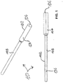
- Figure 1 shows a connecting element semi-finished product 102 for use in the methods and devices according to the invention in a perspective view and in a side view.
- This in Figure 1 Connection semi-finished product 102 shown consists of metal.
- the connecting element semi-finished product 102 is designed overall as a cylindrical rod. Alternatively, but not shown, the connecting element semi-finished product 102 can also be designed as a cylindrical tube.
- the semifinished product 102 has one in the Figure 1 each section 103 shown on the left with a smaller diameter and one in the Figure 1 each section 104 shown on the right with a diameter which is approximately twice as large as the diameter of section 103, the diameter differences between sections 103 and 104 not being important for the present invention.
- the semi-finished product 102 has an end surface 106 at its end facing away from the thinner section 103.
- Figure 1 shows the raw state 110 of the semifinished product 102 before the impression of a longitudinal groove or a rotary driving surface in the section 104
- Figure 1 in the side view of the semi-finished product 102 to the dashed line 136 recognizable shows the longitudinal axis of the semi-finished product 102
- the connecting element semi-finished product 102 of the Figure 1 can also be designed as a tubular semi-finished product 102.
- the semifinished product 102 contains an inner tube cavity concentric to the longitudinal axis 136 with a desired inner tube cross section (not shown).
- Such semi-finished products are used for example in suction drills.
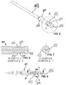
- Figure 2 shows a perspective view of a connecting element according to a first embodiment of the invention.
- Figure 2 shows in the area of section 104 one from the connecting element semi-finished product 102 of FIG Figure 1 Manufactured, provided with an end surface 106 rod-shaped connecting element 100 made of metal.
- the illustrated first embodiment of the connecting element 100 according to the invention represents an axially movable insertion end of a drill or chisel fastened in a tool holder of a hammer drill.
- the connecting element 100 lying in the cylindrical section 104 which with reference to FIG Figures 4-7 will be described in more detail, has two longitudinal grooves 122 which are opposite on the circumference of section 104 and are closed on both sides.
- the longitudinal grooves 122 have a planned length L.
- the longitudinal grooves 122 serve as locking grooves 124 in the illustrated embodiment.
- FIG. 3 shows a perspective view of a connecting element according to a second embodiment of the invention.
- the illustrated second embodiment of a connecting element 100 'according to the invention is described below with reference to FIG Figures 8-11 described in more detail.
- the essential difference between the second embodiment of the connecting element 100 'and the connecting element 100 of FIG Figures 2 and 4-7 is that two - spaced apart from the longitudinal grooves 122 at a right angle along the circumferential direction of the circumference of the section 104 - two likewise opposite one another on the circumference of the section 104 and open towards the end face 106, in the illustrated embodiment of FIG Figures 3 and 8-11 are formed or embossed as essentially U-shaped grooves 162 of rotary driving surfaces 164.
- Figure 4 shows the detailed view A of Figure 2 .
- Figure 5 shows a top view of the connecting element 100 of FIG Figure 2 .
- Figure 6 shows a sectional view through the connecting element 100 according to the in FIG Figure 5 shown section line CC.
- Figure 7 shows a sectional view through the connecting element 100 according to the in FIG Figure 5 shown section line BB.
- Figure 8 shows the detailed view A of the second embodiment of the connecting element 100 'according to Figure 3 .
- Figure 9 shows a partial top view of the connecting element 100 'according to the second embodiment Figure 3 .
- Figure 10 shows a sectional view through the connecting element 100 ′ according to the in FIG Figure 9 shown section line BB.
- Figure 11 shows a sectional view through the connecting element 100 ′ according to the in FIG Figure 9 shown section line CC.
- Figure 12 shows a first embodiment of a device 200 according to the invention for producing a connecting element 100 from a semi-finished connecting element 102, in particular for producing an insertable end of a drill or chisel fastened axially movably in a tool holder of a rotary hammer.
- the device 200 has a die 202 with an inner contour. The inner contour corresponds to at least one planned rotational driving surface 162 of the connecting element 100 '.
- the die 202 has an at least radially movable forming body 206 arranged in a recess 204 in the die 202.
- the forming body 206 is designed as a circular groove punch which can be adjusted and reset radially in the direction of the connecting element semi-finished product 102 according to the double arrow 208.
- the round groove punch 206 serving as the forming body is used to form at least one longitudinal groove 122, which is closed on both sides, into the semifinished product 102.
- One parallel to the longitudinal axis of the semifinished product 102 or parallel to the double arrow 210 in FIG Figure 12 Measured length LR is smaller than the planned length L of the longitudinal groove 122 according to Figure 2 .
- the length LR of the round groove punch 206 corresponds to the diameter of the round groove punch 206, since it has a circular cross section.
- the diameter LR of the round groove punch 206 or the length LR of the shaped body 206 measured parallel to the arrow 210 is preferably between between one and three times the width of the longitudinal groove 122 and less than 30% of the planned length L of the longitudinal groove 122 according to Figure 2 .
- the longitudinal groove 122 is formed in accordance with FIG Figure 2 into the semifinished product 102 by radially advancing the shaped body 206 and then axially displacing the connecting element semifinished product 102 in a longitudinal die opening 214 of the die 202 adapted to the outer periphery of the semifinished product 102 according to arrow 210.
- the longitudinal extension LR of the circular groove punch 206 serving as a radially movable shaping body is preferably one - up to three times one in Figure 5 shown width B of the longitudinal groove 122 closed on both sides.
- the longitudinal extent LR of the round groove punch 206 corresponds to the width B of the planned longitudinal groove 122.
- the device 200 of the Figure 12 shows a press ram 212 and a press ram 216 which act in a longitudinal direction of the die 202 arranged by the double arrow 210 and the press ram 216.
- the press ram 212 is used to form the rotary driving surface 164 when the semi-finished product 102 is inserted into the die 202, and the press ram 216 is used thereon Subsequent shaping of the longitudinal groove 122, which is closed on both sides, and the ejection of the semifinished product 102 from the die 202. With the aid of the compression die 216 and the round groove stamp 206, at least one longitudinal groove 122, which is closed on both sides, can be molded into the semifinished product 102.
- the radially movable round groove punch 206 is essentially fed vertically in the direction of the peripheral surface of the semi-finished product 102 until the round groove stamp 206 dips into the peripheral surface of the semi-finished product 102 in the desired depth of 2.4 mm in this case.
- the radial movement of the circular groove punch 206 directed towards the semifinished product 102 is stopped according to arrow 208.
- the stamp 216 begins the semi-finished product 102 from the die 202 according to the in FIG Figure 12 end of the double arrow 210 shown on the right to move the circular groove punch already immersed in the connecting element semi-finished product 102 relative to the semi-finished product 102 and in this way to form a longitudinal groove in the peripheral surface of the semi-finished product 102.
- the longitudinal groove then has a longitudinal extent which corresponds to the sum of the circumference of the round groove punch 206 and the length of the displacement of the punch 216 into the die 202.
- Figure 13 shows the device of the Figure 12 in a different perspective and immediately before the beginning of the pushing out of the semi-finished product 102 from the longitudinal die opening 214 by the press ram 216.
- a further, second die can be provided with a press die acting in its die longitudinal opening 214 for molding at least one rotary driving surface 162 into the connecting element semi-finished product 102.
- This embodiment is characterized in that in each case an extension of the two longitudinal die openings 214 is arranged with a press die 212, 216, a first press die 212 for molding the at least one rotary driving surface 162 into the semi-finished connecting element 102 an insertion into the second die, and a second press punch 216 for molding the at least one longitudinal groove 122, which is closed on both sides, into the connecting element semi-finished product 102 when it is inserted into the die 202.
- FIGS Figures 14-16 A third embodiment is shown in FIGS Figures 14-16 shown.
- Figure 14 shows a cross section
- Figure 15 shows a longitudinal section
- Figure 16 shows a perspective view of this embodiment.
- the embodiment of the Figures 14-16 is characterized in that at least one wedge 215 is arranged outside the die 202 and approximately at right angles to the die longitudinal opening 214, which presses the at least one longitudinal groove 122, which is closed on both sides, into the connecting element semifinished product 102 onto the at least one shaping body 206 which is radially movable according to the double arrow 208 .
- This embodiment is characterized according to the Figures 14-16 further characterized in that the at least one wedge 215 is machined as an inner cam surface 217 in a sleeve 218 which is rotatably mounted concentrically to the die 202 in a bearing 222, and by rotating the sleeve 218 according to double arrow 220 the force for forming the at least one longitudinal groove 122 closed on both sides is exerted the at least one radially movable forming body 206 is applied.
- FIGS 14-16 show a state in which the forming bodies 206 have formed the longitudinal grooves 122, which are closed on both sides, and a withdrawal of the forming bodies 206 from the grooves 122 is imminent by the sleeve 218 being correspondingly rotated in accordance with the double arrow 220, so that the cams 217 are out of contact with the Cam 217 facing ends of the forming body 206 come.
- a further, not shown fourth embodiment of the device according to the invention or the method according to the invention is characterized in that the die 202 has an inner contour which corresponds to at least one planned rotational driving surface 162 of the connecting element 100 'and this at least one rotating driving surface 162 by inserting the connecting element semi-finished product 102 is molded into the die 202 under force in the direction of a longitudinal axis 210 of the die 202, and the at least one longitudinal groove 122, which is closed on both sides, is impressed by radial infeed of the at least one forming body 206 movable in the die 202 and subsequent axial movement in the direction of the longitudinal axis 210 of the die 202 becomes.
- This embodiment can be further developed by the fact that the at least one longitudinal groove 122, which is closed on both sides, is embossed after the at least one rotary driving surface 162 is formed.
- the method according to the invention can be characterized in that the at least one longitudinal groove which is closed on both sides is impressed during the molding of the at least one rotary driving surface 162, preferably in that the at least one radially movable shaping body 206 has an axial offset with respect to a longitudinal axis 210 of the die with respect to a front end of at least a forming element 206 arranged in the die 202 for the at least one rotary driving surface 162.
- the method according to the invention can furthermore be characterized in that the stamping of the at least one longitudinal groove 122, which is closed on both sides, after the at least one rotary driving surface 162 has ended, begins with the radial infeed of the at least one movable forming body 206 and by pushing the connecting element semi-finished product 102 out of the longitudinal die opening 214 is continued and / or terminated under an axially acting force.
- the method according to the invention can further be characterized in that, in the case of a tubular connecting element semifinished product 102 having a tube inner cavity with a tube inner cross section, in the region of the at least one planned turning driving surface 162 and the at least one planned longitudinal groove 122 closed on both sides, the tube inside cross section by introducing the at least one turning driving surface 162 is reduced or closed, further preferred or alternatively, the inner tube cross section is reduced or closed by previously inserting an inner pin profiled along its longitudinal axis with cross-sectional changes into the connecting element semi-finished product 102.
- the method according to the invention can further be characterized in that the die 202 is divided at least once in the longitudinal direction 210 and the die halves or parts are spaced slightly apart, preferably immediately before being ejected, in relation to a diameter of the connecting element 100, 100 '.
Landscapes
- Engineering & Computer Science (AREA)
- Mechanical Engineering (AREA)
- Forging (AREA)
- Shaping Metal By Deep-Drawing, Or The Like (AREA)
- Percussive Tools And Related Accessories (AREA)
Applications Claiming Priority (1)
| Application Number | Priority Date | Filing Date | Title |
|---|---|---|---|
| DE102018126086.5A DE102018126086B4 (de) | 2018-10-19 | 2018-10-19 | Verbindungselement, Verfahren und Vorrichtung zu seiner Herstellung |
Publications (3)
| Publication Number | Publication Date |
|---|---|
| EP3639946A1 true EP3639946A1 (fr) | 2020-04-22 |
| EP3639946B1 EP3639946B1 (fr) | 2024-11-06 |
| EP3639946B8 EP3639946B8 (fr) | 2025-03-19 |
Family
ID=68051698
Family Applications (1)
| Application Number | Title | Priority Date | Filing Date |
|---|---|---|---|
| EP19198941.7A Active EP3639946B8 (fr) | 2018-10-19 | 2019-09-23 | Procédé et dispositif de fabrication d'un élément de raccordement |
Country Status (5)
| Country | Link |
|---|---|
| US (1) | US11565306B2 (fr) |
| EP (1) | EP3639946B8 (fr) |
| JP (1) | JP7364167B2 (fr) |
| CN (1) | CN111069521A (fr) |
| DE (1) | DE102018126086B4 (fr) |
Cited By (1)
| Publication number | Priority date | Publication date | Assignee | Title |
|---|---|---|---|---|
| DE102020007945A1 (de) | 2020-12-24 | 2022-06-30 | Mac Panther Gmbh | Verbindungsabschnitt mit einseitig offener Verriegelungsnut |
Families Citing this family (1)
| Publication number | Priority date | Publication date | Assignee | Title |
|---|---|---|---|---|
| CN113414288A (zh) * | 2021-06-23 | 2021-09-21 | 王军 | 一种木材加工中机械转子轴的初加工设备 |
Citations (5)
| Publication number | Priority date | Publication date | Assignee | Title |
|---|---|---|---|---|
| EP2361702A1 (fr) | 2010-02-22 | 2011-08-31 | HILTI Aktiengesellschaft | Procédé de fabrication pour une extrémité enfichable |
| DE102010018791A1 (de) * | 2010-04-29 | 2011-11-03 | Illinois Tool Works Inc. | Verfahren zur Herstellung eines länglichen Werkzeugs mit einem Arbeitsabschnitt und einem Einsteckabschnitt |
| EP2458131A2 (fr) | 2010-11-24 | 2012-05-30 | Mac Panther GmbH | Procédé pour la fabrication de l'extrémité enfichable d'un foret |
| EP2641673A2 (fr) * | 2012-03-22 | 2013-09-25 | Mac Panther GmbH | Procédé et dispositif de fabrication d'une section de raccordement comme élément d'un outil |
| EP2839900A1 (fr) | 2013-06-25 | 2015-02-25 | Mac Panther GmbH | Procédé et dispositif de fabrication d'une section de raccordement pourvue d'une face terminale comme élément d'un outil |
Family Cites Families (18)
| Publication number | Priority date | Publication date | Assignee | Title |
|---|---|---|---|---|
| US2405298A (en) | 1944-04-20 | 1946-08-06 | Fleischer John | Twist drill |
| GB631438A (en) | 1947-09-03 | 1949-11-02 | Samuel Smith | Improvements in apparatus for making fluted drills, bits, taps, reamers and the like |
| GB657586A (en) * | 1949-04-08 | 1951-09-19 | Christopher Hodgson Booth | Improvements in or relating to the manufacture of twist drills and like helically fluted metal articles |
| AT279998B (de) * | 1967-05-09 | 1970-03-25 | Rohde & Doerrenberg | Verfahren zum Herstellen von Spiralbohrern od.ähnl Werkzeugen sowie nach dem Verfahren hergestellter Spiralbohrer |
| DE3015893A1 (de) | 1980-04-24 | 1981-10-29 | Hilti AG, 9494 Schaan | Verfahren zum herstellen von mitnahmenuten an werkzeugen |
| GB2264253B (en) * | 1991-06-28 | 1995-03-29 | Usui Kokusai Sangyo Kk | Long extruded metal article of miscellaneous shapes and method of producing the same |
| DE4122158A1 (de) * | 1991-07-04 | 1993-01-07 | Hilgeland Gmbh & Co Geb | Eindruck-hohlnietpresse |
| US6290439B1 (en) * | 1994-12-30 | 2001-09-18 | Black & Decker, Inc. | Method and apparatus for forming parts from a continuous stock material and associated forge |
| DE19915303A1 (de) | 1998-04-03 | 1999-10-14 | Hawera Probst Gmbh | Bohrwerkzeug und Verfahren zu seiner Herstellung |
| DE19859885B4 (de) | 1998-05-20 | 2005-06-16 | Robert Bosch Gmbh | Verfahren zur Herstellung eines Bohrwerkzeugs |
| DE202004021636U1 (de) * | 2004-03-25 | 2009-09-03 | Otto Bihler Handels-Beteiligungs-Gmbh | Vorrichtung zur Herstellung von Sechskantschlüsseln mit Kugelkopf aus Sechskantdraht (Spanlos) |
| JP2005330997A (ja) | 2004-05-18 | 2005-12-02 | Tsubakimoto Chain Co | 円筒状軸受部材及びその製造方法 |
| JP3982706B2 (ja) | 2004-06-04 | 2007-09-26 | 株式会社椿本チエイン | チェーン用油溜まり盲溝付ブシュの製造方法 |
| DE102010014477A1 (de) | 2010-04-09 | 2011-10-13 | Illinois Tool Works Inc. | Verfahren zur Herstellung eines Bohrers |
| DE102010028474A1 (de) | 2010-05-03 | 2011-11-03 | Hilti Aktiengesellschaft | Hohlbohrer und Herstellungsverfahren |
| CN107199254B (zh) | 2017-06-16 | 2018-12-18 | 航天精工股份有限公司 | 一种用于丝材缩扁的模具 |
| DE102018202941B4 (de) * | 2018-02-27 | 2024-01-25 | Kennametal Inc. | Verfahren zur Herstellung eines Rohlings aus Extrusionsmasse sowie Extruder |
| DE102018126093A1 (de) | 2018-10-19 | 2020-04-23 | Mac Panther Gmbh | Verfahren und Vorrichtung zur Herstellung eines Verbindungselementes |
-
2018
- 2018-10-19 DE DE102018126086.5A patent/DE102018126086B4/de active Active
-
2019
- 2019-09-23 EP EP19198941.7A patent/EP3639946B8/fr active Active
- 2019-10-04 JP JP2019183850A patent/JP7364167B2/ja active Active
- 2019-10-18 CN CN201910994854.9A patent/CN111069521A/zh active Pending
- 2019-10-18 US US16/657,081 patent/US11565306B2/en active Active
Patent Citations (5)
| Publication number | Priority date | Publication date | Assignee | Title |
|---|---|---|---|---|
| EP2361702A1 (fr) | 2010-02-22 | 2011-08-31 | HILTI Aktiengesellschaft | Procédé de fabrication pour une extrémité enfichable |
| DE102010018791A1 (de) * | 2010-04-29 | 2011-11-03 | Illinois Tool Works Inc. | Verfahren zur Herstellung eines länglichen Werkzeugs mit einem Arbeitsabschnitt und einem Einsteckabschnitt |
| EP2458131A2 (fr) | 2010-11-24 | 2012-05-30 | Mac Panther GmbH | Procédé pour la fabrication de l'extrémité enfichable d'un foret |
| EP2641673A2 (fr) * | 2012-03-22 | 2013-09-25 | Mac Panther GmbH | Procédé et dispositif de fabrication d'une section de raccordement comme élément d'un outil |
| EP2839900A1 (fr) | 2013-06-25 | 2015-02-25 | Mac Panther GmbH | Procédé et dispositif de fabrication d'une section de raccordement pourvue d'une face terminale comme élément d'un outil |
Cited By (1)
| Publication number | Priority date | Publication date | Assignee | Title |
|---|---|---|---|---|
| DE102020007945A1 (de) | 2020-12-24 | 2022-06-30 | Mac Panther Gmbh | Verbindungsabschnitt mit einseitig offener Verriegelungsnut |
Also Published As
| Publication number | Publication date |
|---|---|
| EP3639946B8 (fr) | 2025-03-19 |
| US11565306B2 (en) | 2023-01-31 |
| US20200122214A1 (en) | 2020-04-23 |
| JP2020066055A (ja) | 2020-04-30 |
| DE102018126086A1 (de) | 2020-04-23 |
| JP7364167B2 (ja) | 2023-10-18 |
| EP3639946B1 (fr) | 2024-11-06 |
| CN111069521A (zh) | 2020-04-28 |
| DE102018126086B4 (de) | 2023-10-12 |
Similar Documents
| Publication | Publication Date | Title |
|---|---|---|
| DE60005010T2 (de) | Steckschlüssel sowie verfahren zu seiner herstellung | |
| EP1986801B1 (fr) | PROCEDE ET DISPOSITIF DE Formation D'UNE DECOUPE OU D'UNE PERFORATION DANS LA PAROI D'UN COMPOSANT FORME PAR UN PROCEDE DE FACONNAGE SOUS HAUTE PRESSION INTERIEURE | |
| DE1452320C3 (de) | Indirekt-Metallstrangpresse zum Herstellen von Rohren | |
| DE10150613A1 (de) | Radlagereinheit für Kraftfahrzeuge | |
| EP2641673B1 (fr) | Procédé et dispositif de fabrication d'une section de raccordement comme élément d'un outil | |
| DE19647963C2 (de) | Verfahren und Vorrichtung zur Herstellung von Löchern am Umfang von Hohlprofilen | |
| DE10328452B3 (de) | Verfahren und Vorrichtung zur Erzeugung eines Loches am Außenumfang eines Hohlprofiles | |
| DE2832063C2 (de) | Vorrichtung zur Herstellung eines drei Metalle umfassenden elektrischen Kontaktes | |
| EP1108483A2 (fr) | Procédé et dispositif pour le fluotournage | |
| EP2344288A2 (fr) | Procédé et dispositif pour réaliser un filetage extérieur sans enlèvement de matière sur des pièces creuses en métal | |
| DE1946178C3 (de) | Verfahren zur Herstellung von Innenprofilen in rohrförmigen Werkstücken | |
| EP3639947B1 (fr) | Procédé et dispositif de fabrication d'un élément de raccordement | |
| DE1299275B (de) | Mehrstufenpresse zur Herstellung von Vielkantkopfbolzen | |
| EP3639946B1 (fr) | Procédé et dispositif de fabrication d'un élément de raccordement | |
| DE10039706B4 (de) | Verfahren zum Einbringen einer Sicke und Drückwalzmaschine | |
| DE102008020242A1 (de) | Verfahren zum Bearbeiten von Blechen sowie Vorrichtung zur Durchführung des Verfahrens | |
| EP0111688B1 (fr) | Méthode de fabrication d'une bague de commutateur pour un commutateur | |
| EP2839900B1 (fr) | Procédé et dispositif de fabrication d'une section de raccordement pourvue d'une face terminale comme élément d'un outil | |
| DE69419206T2 (de) | Verfahren und Vorrichtung zum Herstellen eines metallischen Teils | |
| DE2646502A1 (de) | Verfahren und vorrichtung zur herstellung von metallhuelsen | |
| DE3101123A1 (de) | Verfahren und einrichtung zum verformen eines metallstabes in ein tulpenfoermiges teil durch fliesspressen in einer geschlossenen kammer | |
| EP3863780B1 (fr) | Procédé et dispositif pour matricer des structures superficielles dans une face intérieure d'un tube ou d'une tige de soupape de moteur | |
| EP1250199B1 (fr) | Procede et outil de deformation pour la fabrication de tubes cylindriques par formage par fluage | |
| DE436410C (de) | Herstellung von Speichennippeln | |
| EP2506996B1 (fr) | Procédé et dispositif de production d'une pièce façonnée présentant un trou traversant |
Legal Events
| Date | Code | Title | Description |
|---|---|---|---|
| PUAI | Public reference made under article 153(3) epc to a published international application that has entered the european phase |
Free format text: ORIGINAL CODE: 0009012 |
|
| STAA | Information on the status of an ep patent application or granted ep patent |
Free format text: STATUS: THE APPLICATION HAS BEEN PUBLISHED |
|
| AK | Designated contracting states |
Kind code of ref document: A1 Designated state(s): AL AT BE BG CH CY CZ DE DK EE ES FI FR GB GR HR HU IE IS IT LI LT LU LV MC MK MT NL NO PL PT RO RS SE SI SK SM TR |
|
| AX | Request for extension of the european patent |
Extension state: BA ME |
|
| STAA | Information on the status of an ep patent application or granted ep patent |
Free format text: STATUS: REQUEST FOR EXAMINATION WAS MADE |
|
| 17P | Request for examination filed |
Effective date: 20200422 |
|
| RBV | Designated contracting states (corrected) |
Designated state(s): AL AT BE BG CH CY CZ DE DK EE ES FI FR GB GR HR HU IE IS IT LI LT LU LV MC MK MT NL NO PL PT RO RS SE SI SK SM TR |
|
| STAA | Information on the status of an ep patent application or granted ep patent |
Free format text: STATUS: EXAMINATION IS IN PROGRESS |
|
| 17Q | First examination report despatched |
Effective date: 20220518 |
|
| GRAP | Despatch of communication of intention to grant a patent |
Free format text: ORIGINAL CODE: EPIDOSNIGR1 |
|
| STAA | Information on the status of an ep patent application or granted ep patent |
Free format text: STATUS: GRANT OF PATENT IS INTENDED |
|
| INTG | Intention to grant announced |
Effective date: 20240703 |
|
| GRAS | Grant fee paid |
Free format text: ORIGINAL CODE: EPIDOSNIGR3 |
|
| GRAA | (expected) grant |
Free format text: ORIGINAL CODE: 0009210 |
|
| STAA | Information on the status of an ep patent application or granted ep patent |
Free format text: STATUS: THE PATENT HAS BEEN GRANTED |
|
| AK | Designated contracting states |
Kind code of ref document: B1 Designated state(s): AL AT BE BG CH CY CZ DE DK EE ES FI FR GB GR HR HU IE IS IT LI LT LU LV MC MK MT NL NO PL PT RO RS SE SI SK SM TR |
|
| REG | Reference to a national code |
Ref country code: GB Ref legal event code: FG4D Free format text: NOT ENGLISH |
|
| REG | Reference to a national code |
Ref country code: CH Ref legal event code: EP |
|
| REG | Reference to a national code |
Ref country code: DE Ref legal event code: R096 Ref document number: 502019012426 Country of ref document: DE |
|
| REG | Reference to a national code |
Ref country code: IE Ref legal event code: FG4D Free format text: LANGUAGE OF EP DOCUMENT: GERMAN |
|
| REG | Reference to a national code |
Ref country code: CH Ref legal event code: PK Free format text: TITEL |
|
| REG | Reference to a national code |
Ref country code: CH Ref legal event code: PK Free format text: BERICHTIGUNG B8 |
|
| REG | Reference to a national code |
Ref country code: LT Ref legal event code: MG9D |
|
| REG | Reference to a national code |
Ref country code: NL Ref legal event code: MP Effective date: 20241106 |
|
| PG25 | Lapsed in a contracting state [announced via postgrant information from national office to epo] |
Ref country code: PT Free format text: LAPSE BECAUSE OF FAILURE TO SUBMIT A TRANSLATION OF THE DESCRIPTION OR TO PAY THE FEE WITHIN THE PRESCRIBED TIME-LIMIT Effective date: 20250306 Ref country code: HR Free format text: LAPSE BECAUSE OF FAILURE TO SUBMIT A TRANSLATION OF THE DESCRIPTION OR TO PAY THE FEE WITHIN THE PRESCRIBED TIME-LIMIT Effective date: 20241106 Ref country code: IS Free format text: LAPSE BECAUSE OF FAILURE TO SUBMIT A TRANSLATION OF THE DESCRIPTION OR TO PAY THE FEE WITHIN THE PRESCRIBED TIME-LIMIT Effective date: 20250306 |
|
| PG25 | Lapsed in a contracting state [announced via postgrant information from national office to epo] |
Ref country code: FI Free format text: LAPSE BECAUSE OF FAILURE TO SUBMIT A TRANSLATION OF THE DESCRIPTION OR TO PAY THE FEE WITHIN THE PRESCRIBED TIME-LIMIT Effective date: 20241106 Ref country code: NL Free format text: LAPSE BECAUSE OF FAILURE TO SUBMIT A TRANSLATION OF THE DESCRIPTION OR TO PAY THE FEE WITHIN THE PRESCRIBED TIME-LIMIT Effective date: 20241106 |
|
| PG25 | Lapsed in a contracting state [announced via postgrant information from national office to epo] |
Ref country code: BG Free format text: LAPSE BECAUSE OF FAILURE TO SUBMIT A TRANSLATION OF THE DESCRIPTION OR TO PAY THE FEE WITHIN THE PRESCRIBED TIME-LIMIT Effective date: 20241106 |
|
| PG25 | Lapsed in a contracting state [announced via postgrant information from national office to epo] |
Ref country code: ES Free format text: LAPSE BECAUSE OF FAILURE TO SUBMIT A TRANSLATION OF THE DESCRIPTION OR TO PAY THE FEE WITHIN THE PRESCRIBED TIME-LIMIT Effective date: 20241106 |
|
| PG25 | Lapsed in a contracting state [announced via postgrant information from national office to epo] |
Ref country code: NO Free format text: LAPSE BECAUSE OF FAILURE TO SUBMIT A TRANSLATION OF THE DESCRIPTION OR TO PAY THE FEE WITHIN THE PRESCRIBED TIME-LIMIT Effective date: 20250206 |
|
| PG25 | Lapsed in a contracting state [announced via postgrant information from national office to epo] |
Ref country code: GR Free format text: LAPSE BECAUSE OF FAILURE TO SUBMIT A TRANSLATION OF THE DESCRIPTION OR TO PAY THE FEE WITHIN THE PRESCRIBED TIME-LIMIT Effective date: 20250207 Ref country code: LV Free format text: LAPSE BECAUSE OF FAILURE TO SUBMIT A TRANSLATION OF THE DESCRIPTION OR TO PAY THE FEE WITHIN THE PRESCRIBED TIME-LIMIT Effective date: 20241106 |
|
| PG25 | Lapsed in a contracting state [announced via postgrant information from national office to epo] |
Ref country code: PL Free format text: LAPSE BECAUSE OF FAILURE TO SUBMIT A TRANSLATION OF THE DESCRIPTION OR TO PAY THE FEE WITHIN THE PRESCRIBED TIME-LIMIT Effective date: 20241106 |
|
| PG25 | Lapsed in a contracting state [announced via postgrant information from national office to epo] |
Ref country code: RS Free format text: LAPSE BECAUSE OF FAILURE TO SUBMIT A TRANSLATION OF THE DESCRIPTION OR TO PAY THE FEE WITHIN THE PRESCRIBED TIME-LIMIT Effective date: 20250206 |
|
| PG25 | Lapsed in a contracting state [announced via postgrant information from national office to epo] |
Ref country code: SM Free format text: LAPSE BECAUSE OF FAILURE TO SUBMIT A TRANSLATION OF THE DESCRIPTION OR TO PAY THE FEE WITHIN THE PRESCRIBED TIME-LIMIT Effective date: 20241106 |
|
| PG25 | Lapsed in a contracting state [announced via postgrant information from national office to epo] |
Ref country code: DK Free format text: LAPSE BECAUSE OF FAILURE TO SUBMIT A TRANSLATION OF THE DESCRIPTION OR TO PAY THE FEE WITHIN THE PRESCRIBED TIME-LIMIT Effective date: 20241106 |
|
| PG25 | Lapsed in a contracting state [announced via postgrant information from national office to epo] |
Ref country code: RO Free format text: LAPSE BECAUSE OF FAILURE TO SUBMIT A TRANSLATION OF THE DESCRIPTION OR TO PAY THE FEE WITHIN THE PRESCRIBED TIME-LIMIT Effective date: 20241106 |
|
| PG25 | Lapsed in a contracting state [announced via postgrant information from national office to epo] |
Ref country code: SK Free format text: LAPSE BECAUSE OF FAILURE TO SUBMIT A TRANSLATION OF THE DESCRIPTION OR TO PAY THE FEE WITHIN THE PRESCRIBED TIME-LIMIT Effective date: 20241106 |
|
| PG25 | Lapsed in a contracting state [announced via postgrant information from national office to epo] |
Ref country code: CZ Free format text: LAPSE BECAUSE OF FAILURE TO SUBMIT A TRANSLATION OF THE DESCRIPTION OR TO PAY THE FEE WITHIN THE PRESCRIBED TIME-LIMIT Effective date: 20241106 |
|
| PG25 | Lapsed in a contracting state [announced via postgrant information from national office to epo] |
Ref country code: IT Free format text: LAPSE BECAUSE OF FAILURE TO SUBMIT A TRANSLATION OF THE DESCRIPTION OR TO PAY THE FEE WITHIN THE PRESCRIBED TIME-LIMIT Effective date: 20241106 |
|
| REG | Reference to a national code |
Ref country code: DE Ref legal event code: R097 Ref document number: 502019012426 Country of ref document: DE |
|
| PG25 | Lapsed in a contracting state [announced via postgrant information from national office to epo] |
Ref country code: SE Free format text: LAPSE BECAUSE OF FAILURE TO SUBMIT A TRANSLATION OF THE DESCRIPTION OR TO PAY THE FEE WITHIN THE PRESCRIBED TIME-LIMIT Effective date: 20241106 |
|
| PLBE | No opposition filed within time limit |
Free format text: ORIGINAL CODE: 0009261 |
|
| STAA | Information on the status of an ep patent application or granted ep patent |
Free format text: STATUS: NO OPPOSITION FILED WITHIN TIME LIMIT |
|
| 26N | No opposition filed |
Effective date: 20250807 |
|
| REG | Reference to a national code |
Ref country code: CH Ref legal event code: U11 Free format text: ST27 STATUS EVENT CODE: U-0-0-U10-U11 (AS PROVIDED BY THE NATIONAL OFFICE) Effective date: 20251016 |
|
| PGFP | Annual fee paid to national office [announced via postgrant information from national office to epo] |
Ref country code: FR Payment date: 20250929 Year of fee payment: 7 Ref country code: AT Payment date: 20250929 Year of fee payment: 7 |
|
| PGFP | Annual fee paid to national office [announced via postgrant information from national office to epo] |
Ref country code: DE Payment date: 20251007 Year of fee payment: 7 |
|
| PGFP | Annual fee paid to national office [announced via postgrant information from national office to epo] |
Ref country code: GB Payment date: 20251024 Year of fee payment: 7 |
|
| PGFP | Annual fee paid to national office [announced via postgrant information from national office to epo] |
Ref country code: CH Payment date: 20251016 Year of fee payment: 7 |