EP3640040B1 - Sicherheitsfolie und herstellungsverfahren einer solchen sicherheitsfolie - Google Patents
Sicherheitsfolie und herstellungsverfahren einer solchen sicherheitsfolie Download PDFInfo
- Publication number
- EP3640040B1 EP3640040B1 EP19204424.6A EP19204424A EP3640040B1 EP 3640040 B1 EP3640040 B1 EP 3640040B1 EP 19204424 A EP19204424 A EP 19204424A EP 3640040 B1 EP3640040 B1 EP 3640040B1
- Authority
- EP
- European Patent Office
- Prior art keywords
- film
- safety
- layer
- layers
- substrate
- Prior art date
- Legal status (The legal status is an assumption and is not a legal conclusion. Google has not performed a legal analysis and makes no representation as to the accuracy of the status listed.)
- Active
Links
Images


Classifications
-
- B—PERFORMING OPERATIONS; TRANSPORTING
- B42—BOOKBINDING; ALBUMS; FILES; SPECIAL PRINTED MATTER
- B42D—BOOKS; BOOK COVERS; LOOSE LEAVES; PRINTED MATTER CHARACTERISED BY IDENTIFICATION OR SECURITY FEATURES; PRINTED MATTER OF SPECIAL FORMAT OR STYLE NOT OTHERWISE PROVIDED FOR; DEVICES FOR USE THEREWITH AND NOT OTHERWISE PROVIDED FOR; MOVABLE-STRIP WRITING OR READING APPARATUS
- B42D25/00—Information-bearing cards or sheet-like structures characterised by identification or security features; Manufacture thereof
- B42D25/30—Identification or security features, e.g. for preventing forgery
- B42D25/324—Reliefs
-
- B—PERFORMING OPERATIONS; TRANSPORTING
- B42—BOOKBINDING; ALBUMS; FILES; SPECIAL PRINTED MATTER
- B42D—BOOKS; BOOK COVERS; LOOSE LEAVES; PRINTED MATTER CHARACTERISED BY IDENTIFICATION OR SECURITY FEATURES; PRINTED MATTER OF SPECIAL FORMAT OR STYLE NOT OTHERWISE PROVIDED FOR; DEVICES FOR USE THEREWITH AND NOT OTHERWISE PROVIDED FOR; MOVABLE-STRIP WRITING OR READING APPARATUS
- B42D25/00—Information-bearing cards or sheet-like structures characterised by identification or security features; Manufacture thereof
- B42D25/30—Identification or security features, e.g. for preventing forgery
- B42D25/328—Diffraction gratings; Holograms
-
- B—PERFORMING OPERATIONS; TRANSPORTING
- B42—BOOKBINDING; ALBUMS; FILES; SPECIAL PRINTED MATTER
- B42D—BOOKS; BOOK COVERS; LOOSE LEAVES; PRINTED MATTER CHARACTERISED BY IDENTIFICATION OR SECURITY FEATURES; PRINTED MATTER OF SPECIAL FORMAT OR STYLE NOT OTHERWISE PROVIDED FOR; DEVICES FOR USE THEREWITH AND NOT OTHERWISE PROVIDED FOR; MOVABLE-STRIP WRITING OR READING APPARATUS
- B42D25/00—Information-bearing cards or sheet-like structures characterised by identification or security features; Manufacture thereof
- B42D25/30—Identification or security features, e.g. for preventing forgery
- B42D25/36—Identification or security features, e.g. for preventing forgery comprising special materials
- B42D25/364—Liquid crystals
-
- B—PERFORMING OPERATIONS; TRANSPORTING
- B42—BOOKBINDING; ALBUMS; FILES; SPECIAL PRINTED MATTER
- B42D—BOOKS; BOOK COVERS; LOOSE LEAVES; PRINTED MATTER CHARACTERISED BY IDENTIFICATION OR SECURITY FEATURES; PRINTED MATTER OF SPECIAL FORMAT OR STYLE NOT OTHERWISE PROVIDED FOR; DEVICES FOR USE THEREWITH AND NOT OTHERWISE PROVIDED FOR; MOVABLE-STRIP WRITING OR READING APPARATUS
- B42D25/00—Information-bearing cards or sheet-like structures characterised by identification or security features; Manufacture thereof
- B42D25/30—Identification or security features, e.g. for preventing forgery
- B42D25/36—Identification or security features, e.g. for preventing forgery comprising special materials
- B42D25/378—Special inks
- B42D25/382—Special inks absorbing or reflecting infrared light
-
- B—PERFORMING OPERATIONS; TRANSPORTING
- B42—BOOKBINDING; ALBUMS; FILES; SPECIAL PRINTED MATTER
- B42D—BOOKS; BOOK COVERS; LOOSE LEAVES; PRINTED MATTER CHARACTERISED BY IDENTIFICATION OR SECURITY FEATURES; PRINTED MATTER OF SPECIAL FORMAT OR STYLE NOT OTHERWISE PROVIDED FOR; DEVICES FOR USE THEREWITH AND NOT OTHERWISE PROVIDED FOR; MOVABLE-STRIP WRITING OR READING APPARATUS
- B42D25/00—Information-bearing cards or sheet-like structures characterised by identification or security features; Manufacture thereof
- B42D25/40—Manufacture
- B42D25/45—Associating two or more layers
- B42D25/455—Associating two or more layers using heat
-
- B—PERFORMING OPERATIONS; TRANSPORTING
- B42—BOOKBINDING; ALBUMS; FILES; SPECIAL PRINTED MATTER
- B42D—BOOKS; BOOK COVERS; LOOSE LEAVES; PRINTED MATTER CHARACTERISED BY IDENTIFICATION OR SECURITY FEATURES; PRINTED MATTER OF SPECIAL FORMAT OR STYLE NOT OTHERWISE PROVIDED FOR; DEVICES FOR USE THEREWITH AND NOT OTHERWISE PROVIDED FOR; MOVABLE-STRIP WRITING OR READING APPARATUS
- B42D25/00—Information-bearing cards or sheet-like structures characterised by identification or security features; Manufacture thereof
- B42D25/40—Manufacture
- B42D25/45—Associating two or more layers
- B42D25/46—Associating two or more layers using pressure
-
- B—PERFORMING OPERATIONS; TRANSPORTING
- B42—BOOKBINDING; ALBUMS; FILES; SPECIAL PRINTED MATTER
- B42D—BOOKS; BOOK COVERS; LOOSE LEAVES; PRINTED MATTER CHARACTERISED BY IDENTIFICATION OR SECURITY FEATURES; PRINTED MATTER OF SPECIAL FORMAT OR STYLE NOT OTHERWISE PROVIDED FOR; DEVICES FOR USE THEREWITH AND NOT OTHERWISE PROVIDED FOR; MOVABLE-STRIP WRITING OR READING APPARATUS
- B42D25/00—Information-bearing cards or sheet-like structures characterised by identification or security features; Manufacture thereof
- B42D25/40—Manufacture
- B42D25/45—Associating two or more layers
- B42D25/465—Associating two or more layers using chemicals or adhesives
- B42D25/47—Associating two or more layers using chemicals or adhesives using adhesives
-
- G—PHYSICS
- G09—EDUCATION; CRYPTOGRAPHY; DISPLAY; ADVERTISING; SEALS
- G09F—DISPLAYING; ADVERTISING; SIGNS; LABELS OR NAME-PLATES; SEALS
- G09F3/00—Labels, tag tickets, or similar identification or indication means; Seals; Postage or like stamps
- G09F3/02—Forms or constructions
- G09F3/0291—Labels or tickets undergoing a change under particular conditions, e.g. heat, radiation, passage of time
- G09F3/0292—Labels or tickets undergoing a change under particular conditions, e.g. heat, radiation, passage of time tamper indicating labels
-
- G—PHYSICS
- G09—EDUCATION; CRYPTOGRAPHY; DISPLAY; ADVERTISING; SEALS
- G09F—DISPLAYING; ADVERTISING; SIGNS; LABELS OR NAME-PLATES; SEALS
- G09F3/00—Labels, tag tickets, or similar identification or indication means; Seals; Postage or like stamps
- G09F3/02—Forms or constructions
- G09F3/03—Forms or constructions of security seals
- G09F3/0305—Forms or constructions of security seals characterised by the type of seal used
- G09F3/0341—Forms or constructions of security seals characterised by the type of seal used having label sealing means
-
- G—PHYSICS
- G09—EDUCATION; CRYPTOGRAPHY; DISPLAY; ADVERTISING; SEALS
- G09F—DISPLAYING; ADVERTISING; SIGNS; LABELS OR NAME-PLATES; SEALS
- G09F3/00—Labels, tag tickets, or similar identification or indication means; Seals; Postage or like stamps
- G09F3/02—Forms or constructions
- G09F2003/023—Adhesive
- G09F2003/0245—Differential adhesive strength
-
- G—PHYSICS
- G09—EDUCATION; CRYPTOGRAPHY; DISPLAY; ADVERTISING; SEALS
- G09F—DISPLAYING; ADVERTISING; SIGNS; LABELS OR NAME-PLATES; SEALS
- G09F3/00—Labels, tag tickets, or similar identification or indication means; Seals; Postage or like stamps
- G09F3/02—Forms or constructions
- G09F2003/0276—Safety features, e.g. colour, prominent part, logo
-
- G—PHYSICS
- G09—EDUCATION; CRYPTOGRAPHY; DISPLAY; ADVERTISING; SEALS
- G09F—DISPLAYING; ADVERTISING; SIGNS; LABELS OR NAME-PLATES; SEALS
- G09F3/00—Labels, tag tickets, or similar identification or indication means; Seals; Postage or like stamps
- G09F3/08—Fastening or securing by means not forming part of the material of the label itself
- G09F3/10—Fastening or securing by means not forming part of the material of the label itself by an adhesive layer
Definitions
- the present invention relates to the field of security marking. More particularly, it relates to a security film transferable onto a document, a method for manufacturing such a security film and a method for securing a document by means of such a security film.
- optical security components whose optical effects as a function of observation parameters (orientation relative to the axis of observation, position and dimensions of the light source, etc.) take on characteristic and verifiable configurations.
- the general purpose of these optical components is to provide easily identifiable and differentiating optical effects, for example optical effects visible to the naked eye, from physical configurations that are difficult to reproduce or imitate.
- optical security components for example components of the OVD type for “Optical Variable Device” and particularly the components of the DOVID type for “Diffractive Optical Variable Image Device”, suitable for generating diffractive effects, in reflection or in transmission are known. , commonly referred to as "holograms".
- optical security components forming wavelength filters are known, for example interference filters to achieve, for example, color change effects known by the English term " color shift”, band-pass filters using guided mode resonances of the DID ® type (sold by the company SURYS ® ) or plasmonic resonances, etc.
- label-type multilayer films comprising a support film on which is arranged a set of layers including a set of active layers making it possible to give the optical component a recognizable optical effect and an adhesive layer.
- the average thickness of label-type multilayer films is between 20 ⁇ m and 100 ⁇ m.
- Such multilayer films are intended to be bonded to a support of a document to be secured, for example by hot bonding, by means of the adhesive layer.
- EP 0 401 466 A1 describes the preamble of claim 1.
- multilayer transfer films designed to be transferred locally onto the document to be secured, in particular by hot pressing. After the transfer, the support film that was used to manufacture the component is removed.
- the component after transfer is therefore much thinner (typically less than about ten micrometers thick) than a label-type multilayer film. It generally covers a limited part of the surface to be protected, generally greater than 10 mm 2 and typically a few cm 2 ; it can be one-piece or consist of several contiguous or disjoint fragments.
- FIG. 1 thus illustrates a multilayer transfer film 10 configured to be transferred onto a document. It generally comprises a support film 11, a detachment layer 12, a set of so-called “optically active” layers 13 or “security layers” making it possible to give the multilayer transfer film a recognizable optical effect, and an adhesive layer 14.
- the transfer film is transferred onto a surface of a substrate 100 of a document to be secured by means of the adhesive layer 14, for example by hot pressing, the detachment layer 12 allows total detachment of the part to be removed, namely the support film 11 and the release layer 12.
- a protective film is applied to the entire substrate of the document locally coated with the set of optically active layers, in order to confer on the whole of the surface a physico-chemical protection against natural or artificial aggressions.
- Such multilayer transfer films are for example described in the published patent application EP 1770670 or published patent application FR 2 968 239 . More specifically, the document EP 1770670 describes a heat transferable multilayer transfer film, in the form of a continuous strip, and used to transfer onto a document of value one or more optical components whose shapes are determined by the shape(s) of the iron marking used for hot pressing.
- An object of the invention is to provide a transferable security film on a substrate of a document, the optically active layers of which, i.e. forming the optical security component, have the ability to separate from the substrate according to a predetermined pattern of destruction. checked in response to a subsequent attempt to tear off the component with fraudulent intent, in particular when the latter is covered with an additional protective film.
- the present description relates to a transferable security film on a substrate of a document to be secured, as described in one of claims 1 or 5.
- Such a security film allows, after transfer of the security film to the substrate of the document and during a subsequent and ill-intentioned tearing attempt of the set of security layers, a selective and controlled destruction of said set of layers according to the destruction pattern which reproduces the discontinuous pattern of the controlled destruction layer. It is therefore no longer possible for a counterfeiter to extract all or a substantial part of an optical security component formed by said set of security layers.
- the security film further comprises an adhesive layer for fixing the security film to the substrate.
- the adhesive layer is in contact with a second face of the set of security layers, opposite said first face.
- the adhesive layer comprises a material selected from the group comprising: a resin based on an acrylic copolymer, and/or a styrene-acrylate copolymer and/or an ethylene vinyl acetate (EVA) copolymer, which may contain silica.
- the thickness of the adhesive layer is between 1.0 ⁇ m and 6.0 ⁇ m.
- the adhesive layer is continuous, in order to ensure uniform adhesion of the security film to the substrate.
- the security film further comprises a detachment layer, uniform, in contact with the support film, of a different nature from that of the controlled destruction layer.
- the detachment layer makes it possible to facilitate the detachment of the support film during the transfer to the substrate.
- the release layer comprises a material selected from the group comprising: a natural wax (e.g. candelilla, montan, carnauba or equivalent), a synthetic wax, a polyurethane resin, an acrylic resin, a cellulosic resin, or a combination of these materials. During a hot transfer, for example, these materials can melt and allow total detachment by creep.
- the thickness of the detachment layer is less than 0.5 ⁇ m.
- a detachment of the support film during transfer from the substrate can be facilitated by means, for example, of a pretreatment of the surface of the support film.
- the detachment layer and/or the pretreatment of the support film allow total elimination of the support film after transfer of the security film to the substrate, without this total elimination causing degradation of the set of security layers.
- the support film comprises a material selected from the group comprising: a polyethylene terephthalate (PET), a polypropylene (PP), a polystyrene (PS).
- PET polyethylene terephthalate
- PP polypropylene
- PS polystyrene
- the controlled destruction layer comprises a material selected from the group comprising: a polyacrylate, a polyvinyl chloride, a polyvinyl acetate, a polyurethane, a polycarbonate, a polyester, ethylene vinyl acetate copolymer, hydrocarbon resin, chlorinated polyolefin, polyvinyl alcohol, fluoropolymer, melamine resin, ketone/formaldehyde resin, epoxy resin, phenolic resin, urea resin, synthetic resin, a polystyrene, a polymeric cellulose compound, a polyamide, a liquid crystal polymer (LCPs), or a combination of the aforementioned materials.
- a material selected from the group comprising: a polyacrylate, a polyvinyl chloride, a polyvinyl acetate, a polyurethane, a polycarbonate, a polyester, ethylene vinyl acetate copolymer, hydrocarbon resin, chlorinated polyolefin, polyvinyl alcohol
- security films according to the present description comprising layers of controlled destruction comprising a fluoropolymer, for example a polyvinylidene fluoride (PVDF), for example a crystallizing PVDF in the alpha form, have shown satisfactory selective destruction of an optical component security resulting from the transfer of the security film onto a document to be secured.
- PVDF polyvinylidene fluoride
- tests for measuring the peeling force necessary for tearing off the optical security component have shown a profile of the peeling force characteristic of a pattern of controlled destruction.
- the controlled destruction layer comprises at least one crosslinking agent in order to induce a bridging reaction with a layer in contact with said controlled destruction layer, and initially exhibiting little affinity with it.
- the controlled destruction layer comprises between 0.5% and 2% by weight of said crosslinking agent.
- said crosslinking agent is selected from the group comprising: a carbodiimide, a melamine resin, an aziridine, an isocyanate or a combination of the aforementioned materials.
- a bridging reaction can for example be triggered by a hot lamination process.
- the thickness of the controlled destruction layer is between 100 nm and 2 ⁇ m, for example between 200 nm and 1 ⁇ m.
- the controlled destruction layer being discontinuous, the thickness in question corresponds to a local thickness, i.e. to a thickness of the controlled destruction layer corresponding to the case where the layer is continuous, i.e. say without empty parts.
- the thickness in question does not correspond to an average thickness taking into account the empty parts and the solid parts of the controlled destruction layer.
- the controlled destruction layer is thin enough not to be detected on visual inspection.
- the controlled destruction layer is transparent in the spectral band of visible light.
- transparent layer is meant in the present description a layer having a transmission at least greater than or equal to 80%, for example greater than or equal to 90% in the observation spectral band.
- the controlled destruction layer comprises markers detectable only in a given spectral band.
- said spectral band is included in UVA, UVB, UVC, infrared, or a combination of these spectral bands.
- the markers are detectable under the action of light, thermal (e.g. thermochromic pigments), electromagnetic or piezoelectric stimulation.
- the markers can comprise an ink of the IRB900 type, defined in ISO1831 and detectable only in the near infrared (850 nm to 950 nm).
- the set of security layers comprises a structured layer.
- Said structured layer can be produced, for example, by hot stamping a thermoformable layer or by cold molding in a molding layer, followed by a crosslinking operation, according to a technology known by its English name of "casting”. .
- the set of security layers comprises a reflective, continuous or discontinuous layer.
- the reflective layer is formed of a metallic coating, for example produced by vacuum deposition of one or more metallic films, comprising for example aluminium, chromium, copper or an alloy of these metals.
- the reflective layer can also be formed of a layer of transparent dielectric material in the visible and of an optical refractive index distinct from that of the surrounding layers, that is to say having a refractive index differential greater than 0.2, advantageously greater than 0.5.
- the transparent dielectric material may for example comprise zinc sulphide (ZnS) or titanium dioxide (TiO 2 ) or another material.
- the reflective layer may comprise alternating layers of metallic material and layers of dielectric material, such as those mentioned above.
- the reflective layer is continuous. In other examples, it is discontinuous.
- the continuous or discontinuous character of the reflective layer is provided according to the needs of contrast or transparency of the set of security layers.
- the set of security layers may further comprise an optional encapsulation layer.
- a set of security layers in a security film according to the present description can be intended to form, in a non-limiting manner, a DOVID-type security optical component, a zero-order reflective component as described for example in the published patent applications EP2567270 , EP3129238 , Or EP2264491 , a component with a plasmonic effect as described for example in the published patent application WO2013060817 .
- the thickness of the set of security layers is between 0.5 ⁇ m and 1.5 ⁇ m.
- the thickness of the security film once the support film has been removed is less than 10 ⁇ m.
- the present description relates to a method of manufacturing a security film according to the first aspect.
- the present description relates to a method of manufacturing a security film, as described in claim 6.
- a surface treatment of one or more layers is carried out before or after the deposition of said layers.
- Said surface treatment can for example include a corona treatment or else a plasma treatment.
- Plasma treatment can be carried out at ambient pressure (“atmospheric plasma”), or under high vacuum, at a pressure of the order of Pascal.
- the surface treatment of the layers can allow better adhesion between layers depending on the nature of the materials involved. Thus, in certain cases, a surface treatment can make it possible to moderate apparent incompatibilities related to the nature of the materials.
- the controlled destruction layer is printed on the detachment layer or on the support film, on a limited surface, between 30% and 70%, for example between 40% and 60%, of the total area of the release layer or carrier film.
- too small a printing surface of the controlled destruction layer will have the effect of disfavoring controlled destruction by tearing off the protective film, because the controlled destruction layer will be entrained in an exacerbated manner by the protective film.
- an excessively large printing surface of the destruction layer could also disadvantage controlled destruction, because the controlled destruction layer will be retained in an exacerbated manner on the substrate.
- the printing of the discontinuous controlled destruction layer comprises the printing of regular or irregular patterns.
- the patterns may include dimples or other finished surfaces and/or straight lines and/or curved lines and/or jagged lines and/or alphanumeric characters.
- Printing methods can include offset (indirect printing), rotogravure, screen printing, or even flexography, for rapid printing, for example industrial printing in series.
- Ink-jet type printing can also be used to allow variable, "à la carte" printing of the patterns of the controlled destruction layer.
- the transfer of said security film onto said substrate is obtained by hot pressing.
- the method for protecting a secure document according to the third aspect further comprises depositing a protective film on said at least part of a first face of said substrate.
- the document is not only protected from natural attacks such as mechanical attacks (abrasion, friction) and physicochemical attacks (humidity, contact with a liquid) but also secured in the event of malicious tearing. Indeed, in a document thus secured, the applicant has shown that a tearing attempt would result in a partial, predictable and controlled tearing of the set of security layers, resulting from the presence of the discontinuous controlled destruction layer.
- optical security component thus transferred can cover a limited surface of the substrate.
- it can be monobloc or consist of several fragments, contiguous or disjoint.
- the protective film is not only in contact with at least one optical security component but is also in contact with the substrate, and thus circumscribes one or more component blocks security optics.
- the protective film must be able to adhere to the substrate to circumscribe the part or parts of the at least one face of the substrate coated with the at least one first optical security component, while allowing controlled destruction of the at least one component safety optics during a malicious pull-out attempt.
- the protective film comprises a polymer material.
- the protective film may comprise a layer of polyethylene PE and a layer of polyester PET, in which said layer of PE is the layer of the protective film in contact, in particular, with the layer of controlled destruction.
- the layer of polyethylene PE can be coextruded on the layer of polyester PET.
- the protective film is composed of a layer of PE coextruded on a layer of PET, during the deposition of the protective film, it is the layer of PE which ensures the thermal bonding on the substrate thanks to the thermofusible nature of PE linked to its lower softening temperature than PET.
- the thickness of the protective film is between 75 ⁇ m and 300 ⁇ m, for example between 100 ⁇ m and 300 ⁇ m.
- the thickness of the protective film is between 150 ⁇ m and 250 ⁇ m.
- the controlled destruction layer comprises a fluoropolymer, for example a polyvinylidene fluoride (PVDF), for example a crystallizing PVDF in the alpha form;
- PVDF polyvinylidene fluoride
- the controlled destruction layers have shown satisfactory selective destruction of an optical security component resulting from the transfer of the security film onto a document to be secured, in particular after depositing a film of protection, and in particular a protective film comprising a layer of polyethylene PE and a layer of polyester PET in which said layer of PE is the layer of the protective film in contact, in particular, with the controlled destruction layer.
- the substrate is a physical support comprising a material which can be selected from the group comprising: a paper, a plastic, a synthetic paper such as TESLIN ® or else TYVEK ® .
- the substrate is opaque, i.e. with a transmittance of less than or equal to 20%, for example less than or equal to 10%.
- the substrate may comprise an opaque material present in a sufficient quantity in the substrate to make said substrate opaque.
- FIG. 2 A first example of a security film 20 according to the present description is represented on the FIG. 2 .
- the safety film 20 as illustrated on the FIG. 2 comprises a support film 21 intended to be removed after transfer, and a set of security layers 23 conferring a recognizable optical effect on the security film 20.
- the security film 20 of the FIG.2 includes in this example an adhesive layer 24 (optional) for fixing the security film 20 on a substrate 100 of a secure document.
- the adhesive layer 24 is in contact with one side of the set of security layers.
- the security film 20 further comprises a controlled destruction layer 26, discontinuous, arranged between the support film 21 and one face of the assembly of security layers 23 opposite the face in contact with the adhesive layer 24.
- the controlled destruction 26 is intended to remain fixed to the set of security layers 23 during the transfer of the security film to the substrate 100.
- the set of security layers 23 comprises an at least partially structured layer 232, a reflective layer 231 and an optional encapsulation layer 233.
- the layer 232 comprises for example polymethyl methacrylate (PMMA).
- Layer 231 may be discontinuous.
- the structuring of the layer 232 makes it possible to form, according to known means of the state of the art, an optical effect recognizable by an observer, in reflection or in transmission.
- the set of security layers forms, for example and in a non-limiting way, an optical component of the DOVID type, a reflective component at zero order using resonances of guided modes of the DID ® type, a component with a plasmonic effect.
- the set of security layers can also be able to generate an interference filter, in which case a structuring of the layer 232 is not always necessary.
- the set of security layers can thus comprise a stack of transparent dielectric layers and/or transparent semi-conducting layers and/or semi-transparent metallic layers.
- the set of security layers can comprise any multilayer arrangement suitable for forming, in known manner, a recognizable optical effect, for example a static and/or dynamic colored effect, which varies according to the viewing conditions.
- the security film further comprises a release layer 22.
- This layer 22 is optional.
- the detachment layer 22 is uniform, in contact with the support film 21, of a different nature from that of the controlled destruction layer 26, and configured to allow the detachment of the support film 21 during transfer to the substrate 100 for the protection of a secure document.
- the support film 21 may also have a coating such as to facilitate its detachment, in particular in the case where the detachment layer 22 is absent.
- the transfer of the security film according to the present description can be done hot or cold.
- the hot transfer can be carried out by pressing the security film on the substrate 100 of the document to be secured.
- cold transfer for example in the case of a transfer of the " cold stamping " type, can be carried out by UV crosslinking of the adhesive layer 24 of the security film on the substrate 100.
- the adhesive layer is not contained in the safety film. In this case, an adhesive layer can be affixed to the substrate 100 prior to the transfer of the security film.
- the substrate 100 is for example a physical support comprising a material which can be selected from the group comprising: a paper, a plastic, a synthetic paper such as TESLIN ® , or else TYVEK ® .
- the support film 21 can be removed.
- FIG. 3 illustrates an example of a document secured by means of a method according to the present description, resulting for example from the transfer of a security film according to the example of the FIG. 2 , on a substrate 100 of a document.
- the secure document 30 as shown in the FIG. 3 comprises the substrate 100 and at least one first optical security component resulting from the transfer of a security film according to the present description, onto at least part of a first face of the substrate 100.
- the optical security component thus comprises the set of security layers 23 and the controlled destruction layer 26, the support film having been detached with the release layer, if applicable.
- the secure document 30 further comprises a protective film 31 deposited on the whole of said at least one first face of said substrate 100 coated with said at least one first optical security component.
- the component thus transferred can cover a limited part of the surface to be protected, typically a few cm 2 , and it can be in one piece or consist of several fragments, the surface of each fragment being for example greater than 5 mm 2 , for example greater than 2 mm 2 , said fragments being contiguous or disjoint.
- the protective film 31 is then not only in contact with at least one optical security component but can also be in contact with at least a part of the substrate 100 and thus circumscribe one or more optical security components.
- the protective film 31 When the protective film 31 covers the optical security component, it is in contact with the controlled destruction layer 26, but also with one side of the set of security layers 23, due to the discontinuous nature of the controlled destruction 26.
- the protective film 31 may for example comprise a layer of polyethylene PE coextruded on a layer of polyester PET, the PE layer being intended to be in contact with the controlled destruction layer 26 and the set of security layers 23.
- the thickness of the protective film 31 can be between 75 ⁇ m and 300 ⁇ m.
- FIG.4 illustrates a possible effect of malicious tearing of the protective film 31 from the secure document 30.
- the attempt to tear off the protective film 31 from the secure document 30 causes a selective, predictable and controlled destruction of the set of security layers 23 in the sense that the destruction pattern of the set of security layers 23 reproduces the discontinuous pattern of the controlled destruction layer over the entire tear-off surface.
- the selective and controlled destruction of the set of security layers 23 can also be reinforced by a vertical adhesion gradient within the secure document 30.
- This vertical adhesion gradient or adhesion differential can result directly from the nature of the materials involved in the layers.
- the inventors believe that affinities between materials included in different layers, at the level of the junction between layers, that is to say at the surface of the layers, generate as many differentiated weaknesses within of the secure document 30.
- the difference in adhesion between the set of security layers 23 and the protective film 31 on the one hand and between the controlled destruction layer 26 and the set of security layers 23 d on the other hand can be guided by the nature of the materials forming these layers.
- crosslinking agents within one or more layers can also influence these differentiated weaknesses by inducing the formation of bridges between layers.
- the adhesion differential can also result from the choice of the thicknesses of each layer, generating mechanical stresses during tearing which, in combination with the nature of the materials included in the layers, will also influence the pattern of destruction of the assembly. layers of security 23.
- a break at the interface between the adhesive layer 24 and the set of security layers 23, or a break between two layers of different natures included in the set of security layers 23 are also conceivable according to one or more exemplary embodiments according to the present description.
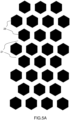
- FIG. 5A illustrates a regular printing pattern of a controlled destruction layer 26 of an example of security film according to the present description.
- the printing of the discontinuous controlled destruction layer 26 is carried out directly on the support film 21 (see the white areas corresponding to the walls between the cells).
- FIG. 5B shows an irregular print pattern of a controlled destruction layer 26 of another example of security film according to the present description.
- the hexagonal pattern shown on the FIG. 5A is made more complex by means of a curved line which is superimposed on the regular pattern.
- the patterns can be obtained for example and according to certain printing techniques by a printing cylinder comprising an engraving pattern which is the negative of the desired printing pattern for the controlled destruction layer.
- FIG. 6A and 6B A demonstration of the technical effect of controlled destruction of an optical security component according to the present description is illustrated on the FIG. 6A and 6B , representing peel strength measurements made in accordance with the technique described in ISO/IEC 10373-1:1998(E).
- a peeling between layers of a card takes place according to a displacement in a linear peeling direction, the direction of the applied peeling force being maintained at 90° to the plane of the card throughout the displacement.
- FIG. 6A illustrates the measurement of the peel force applied, that is to say the force required to tear off the protective film from a substrate coated in places with an optical security component.
- the peel force expressed in arbitrary units and represented as the ordinate on the FIG. 6A , corresponds to the force required for peeling off the protective film, as a function of a displacement along a linear peeling direction, expressed in mm, represented on the abscissa on the graph.
- the optical security component does not comprise a controlled destruction layer according to the present description.
- the substrate of the FIG. 6A is made of Teslin ® and the protective film of coextruded PET/PE, the PE layer of the protective film being the one in contact with the optical security component and with the Teslin ® in places where the latter is not covered with the component security optics.
- the lower part of the peel force curve obtained ie between about 40 mm and 60 mm, corresponds to the tearing forces at the level of the safety component, and illustrates the case of a tearing without controlled destruction effect, the part bottom of the curve being smooth.
- the optical security component remained attached to the Teslin ® . It should be noted that in the case of a rupture at an interface between two layers of the optical security component, or else a cohesive rupture of the adhesive layer, a similar curve of the peel force would have been obtained, ie a smooth plateau with a different peel strength value.
- FIG. 6B illustrates the case where the same PET/PE protective film is torn from a Teslin ® substrate partially coated with an optical security component, in which, this time, a controlled destruction layer is present, according to the this description.
- the lower part of the peel force curve ie between approximately 40 mm and 60 mm, and corresponding to the tearing forces at the level of the safety component no longer appears in the form of a smooth plateau.
- the controlled destruction effect is recognizable on the curve in the form of several undulations resulting from the discontinuity of the controlled destruction layer.
- the security film according to the invention and the process for manufacturing said film comprise various variants, modifications and improvements which will appear obvious to those skilled in the art, it being understood that these various variants, modifications and improvements form part of the scope of the invention as defined by the following claims.
Landscapes
- Engineering & Computer Science (AREA)
- Manufacturing & Machinery (AREA)
- General Physics & Mathematics (AREA)
- Physics & Mathematics (AREA)
- Chemical & Material Sciences (AREA)
- Theoretical Computer Science (AREA)
- Crystallography & Structural Chemistry (AREA)
- Computer Security & Cryptography (AREA)
- Health & Medical Sciences (AREA)
- Chemical Kinetics & Catalysis (AREA)
- General Chemical & Material Sciences (AREA)
- General Health & Medical Sciences (AREA)
- Toxicology (AREA)
- Laminated Bodies (AREA)
- Credit Cards Or The Like (AREA)
Claims (15)
- Sicherheitsfilm (20), der auf ein Substrat (100) eines zu sichernden Dokuments übertragbar ist, wobei der Sicherheitsfilm (20) aufweist:- einen Trägerfilm (21), der so ausgebildet ist, dass er nach der Übertragung des Sicherheitsfilms auf das Substrat entfernt werden kann;- eine einheitliche Trennschicht (22), die mit dem Trägerfilm (21) in Kontakt steht und so ausgebildet ist, dass sie das Entfernen des Trägerfilms (21) nach der Übertragung des Sicherheitsfilms auf das Substrat (100) ermöglicht;- eine Ansammlung von Sicherheitsschichten (23), die dem Sicherheitsfilm (20) einen erkennbaren optischen Effekt verleihen; wobei der Sicherheitsfilm dadurch gekennzeichnet ist, dass er Folgendes umfasst- eine kontrollierte Zerstörungsschicht (26), die im Spektralbereich des sichtbaren Lichts transparent ist, diskontinuierlich gemäß einem vorgegebenen Zerstörungsmuster, die zwischen dem Trägerfilm (21) und einer ersten Fläche der Anordnung von Sicherheitsschichten (23) angeordnet ist, wobei die kontrollierte Zerstörungsschicht von anderer Art ist als die Trennschicht und in Kontakt mit der Trennschicht (22) und der ersten Fläche der Anordnung von Sicherheitsschichten (23) steht, wobei die kontrollierte Zerstörungsschicht so ausgebildet ist, dass sie bei der Übertragung des Sicherheitsfilms auf das Substrat (100) an der Ansammlung von Sicherheitsschichten (23) befestigt bleibt, und so ausgebildet ist, dass sie nach der Übertragung des Sicherheitsfilms auf das Substrat bei einem Versuch, die Ansammlung von Sicherheitsschichten abzureißen, eine selektive Zerstörung der Ansammlung von Sicherheitsschichten gemäß dem Zerstörungsmuster bewirkt.
- Sicherheitsfilm (20) nach Anspruch 1, ferner aufweisend eine Klebeschicht (24) zur Befestigung des Sicherheitsfilms (20) auf dem Substrat (100), wobei die Klebeschicht (24) mit einer zweiten Fläche der Anordnung von Sicherheitsschichten (23) gegenüber der ersten Fläche in Kontakt steht.
- Sicherheitsfilm (20) nach einem der vorhergehenden Ansprüche, wobei die Dicke der kontrollierten Zerstörungsschicht (26) zwischen 100 nm und 2 µm liegt.
- Sicherheitsfilm (20) nach einem der vorhergehenden Ansprüche, wobei die kontrollierte Zerstörungsschicht (26) Markierungen aufweist, die nur in einem vorgegebenen Spektralband nachweisbar sind.
- Sicherheitsfilm (20), der auf ein Substrat (100) eines zu sichernden Dokuments übertragbar ist, wobei der Sicherheitsfilm (20) aufweist:- Einen Trägerfilm (21), der so ausgebildet ist, dass er nach der Übertragung des Sicherheitsfilms auf das Substrat entfernt wird;- eine Anordnung von Sicherheitsschichten (23), die dem Sicherheitsfilm (20) einen erkennbaren optischen Effekt verleihen;- eine kontrollierte Zerstörungsschicht (26), transparent im Spektralbereich des sichtbaren Lichts, diskontinuierlich gemäß einem vorgegebenen Zerstörungsmuster, in Kontakt mit einer Fläche des Trägerfilms und einer ersten Fläche der Anordnung von Sicherheitsschichten (23), wobei die kontrollierte Zerstörungsschicht so ausgebildet ist, dass sie nach dem Übertragen des Sicherheitsfilms auf das Substrat (100) an der Anordnung von Sicherheitsschichten (23) befestigt bleibt, und so ausgebildet ist, dass sie nach dem Übertragen des Sicherheitsfilms auf das Substrat bei einem Versuch, die Anordnung von Sicherheitsschichten abzureißen, eine selektive Zerstörung der Anordnung von Sicherheitsschichten gemäß dem Zerstörungsmuster bewirkt.
- Verfahren zur Herstellung eines Sicherheitsfilms, der auf ein Substrat (100) eines zu sichernden Dokuments übertragbar ist, folgende Schritte aufweisend:- Bereitstellen eines Trägerfilms (21), wobei der Trägerfilm so ausgebildet ist, dass er nach der Übertragung des Sicherheitsfilms auf das Substrat entfernt werden kann;- optionales Aufbringen einer Trennschicht (22) auf den Trägerfilm (21);- Drucken auf die Trennschicht (22) oder direkt auf den Trägerfilm, falls keine Trennschicht vorhanden ist, einer kontrollierten Zerstörungsschicht (26), die im Spektralband des sichtbaren Lichts transparent ist und gemäß einem vorgegebenen Zerstörungsmuster diskontinuierlich ist;- Aufbringen einer Anordnung von Sicherheitsschichten (23), die dem Sicherheitsfilm (20) einen erkennbaren optischen Effekt verleihen, auf die Trennschicht (22) oder den Trägerfilm (21) nach dem Drucken der Zerstörungsschicht, wobei die kontrollierte Zerstörungsschicht so ausgebildet ist, dass sie nach der Übertragung des Sicherheitsfilms auf das Substrat (100) an der Anordnung von Sicherheitsschichten (23) befestigt bleibt, und so ausgebildet ist, dass sie nach der Übertragung des Sicherheitsfilms auf das Substrat bei einem Versuch, die Anordnung von Sicherheitsschichten abzureißen, eine selektive Zerstörung der Anordnung von Sicherheitsschichten gemäß dem Zerstörungsmuster bewirkt.
- Verfahren nach Anspruch 6, wobei die kontrollierte Zerstörungsschicht (26) auf die Trennschicht (22) oder den Trägerfilm (21) gedruckt ist, und zwar auf einer Fläche zwischen 30 % und 70 % der Gesamtfläche der Trennschicht (22) oder des Trägerfilms (21).
- Verfahren nach einem der Ansprüche 6 oder 7, wobei das Bedrucken der diskontinuierlichen kontrollierten Zerstörungsschicht (26) das Drucken von Mustern umfasst, die Waben oder andere fertige Oberflächen und/oder gerade Linien und/oder gekrümmte Linien und/oder gebrochene Linien und/oder alphanumerische Zeichen aufweisen.
- Verfahren nach einem der Ansprüche 6 bis 8, welches ferner das Aufbringen einer Klebeschicht (24) auf die genannte Anordnung von Sicherheitsschichten aufweist.
- Verfahren zum Schutz eines Dokuments (30), folgende Schritte aufweisend:- Herstellen eines Sicherheitsfilms (20) nach einem der Ansprüche 6 bis 9 ;- Übertragen des Sicherheitsfilms (20) auf mindestens einen Teil einer ersten Fläche eines Substrats (100) des Dokuments (30), um dieses zu sichern;- Entfernen des Trägerfilms.
- Verfahren nach Anspruch 10, wobei die Übertragung des Sicherheitsfilms durch Heißpressen erfolgt.
- Verfahren nach einem der Ansprüche 10 oder 11, das ferner das Aufbringen eines Schutzfilms (31) auf den mindestens einen Teil einer ersten Fläche des Substrats (100) aufweist.
- Verfahren nach Anspruch 12, wobei:- der Schutzfilm (31) eine Schicht aus Polyethylen PE und eine Schicht aus Polyester PET aufweist;- die PE-Schicht mit der kontrollierten Zerstörungsschicht (26) in Kontakt steht.
- Verfahren nach einem der Ansprüche 12 oder 13, wobei die Dicke des Schutzfilms (31) zwischen 75 µm und 200 µm liegt.
- Verfahren nach einem der Ansprüche 12 bis 14, wobei die kontrollierte Zerstörungsschicht ein Fluorpolymer, beispielsweise Polyvinylidenfluorid (PVDF), aufweist.
Applications Claiming Priority (1)
| Application Number | Priority Date | Filing Date | Title |
|---|---|---|---|
| FR1859700A FR3087385B1 (fr) | 2018-10-19 | 2018-10-19 | Film de securite et document securise au moyen d'un film de securite |
Publications (2)
| Publication Number | Publication Date |
|---|---|
| EP3640040A1 EP3640040A1 (de) | 2020-04-22 |
| EP3640040B1 true EP3640040B1 (de) | 2023-06-07 |
Family
ID=65444011
Family Applications (1)
| Application Number | Title | Priority Date | Filing Date |
|---|---|---|---|
| EP19204424.6A Active EP3640040B1 (de) | 2018-10-19 | 2019-10-21 | Sicherheitsfolie und herstellungsverfahren einer solchen sicherheitsfolie |
Country Status (2)
| Country | Link |
|---|---|
| EP (1) | EP3640040B1 (de) |
| FR (1) | FR3087385B1 (de) |
Families Citing this family (2)
| Publication number | Priority date | Publication date | Assignee | Title |
|---|---|---|---|---|
| WO2021001698A1 (en) * | 2019-07-01 | 2021-01-07 | Agarwal, Sonia | Security label stock and system for manufacturing thereof |
| DE102021203749A1 (de) * | 2021-04-15 | 2022-10-20 | Scribos Gmbh | Sicherheitsetikett, Serie an Sicherheitsetiketten, Authentifizierungssystem mit einer Serie an Sicherheitsetiketten sowie Verfahren zur Herstellung eines Sicherheitsetiketts |
Family Cites Families (10)
| Publication number | Priority date | Publication date | Assignee | Title |
|---|---|---|---|---|
| EP0201323B1 (de) | 1985-05-07 | 1994-08-17 | Dai Nippon Insatsu Kabushiki Kaisha | Artikel mit transparentem Hologramm |
| EP0401466B1 (de) * | 1989-06-05 | 1995-06-21 | Landis & Gyr Technology Innovation AG | Schichtverbund mit Beugungstrukturen |
| FR2891650B1 (fr) | 2005-09-30 | 2007-12-07 | Hologram Ind Sarl | Procede pour la securisation holographique d'un document et la fabrication d'un tel document. film pour la mise en oeuvre de ce procede et document ainsi securise. |
| CA2543790C (en) | 2006-04-24 | 2014-03-04 | Corporation De L`Ecole Polytechnique De Montreal | Interference security image structure |
| EP2264491B1 (de) | 2009-06-15 | 2017-08-09 | CSEM Centre Suisse d'Electronique et de Microtechnique SA - Recherche et Développement | Diffraktionsfilter nullter Ordnung und Herstellungsverfahren dafür |
| FR2959830B1 (fr) | 2010-05-07 | 2013-05-17 | Hologram Ind | Composant optique d'authentification et procede de fabrication dudit composant |
| FR2968239B1 (fr) | 2010-12-07 | 2012-12-21 | Hologram Ind | Produit securise et methode de fabrication dudit produit securise |
| FR2982038B1 (fr) | 2011-10-28 | 2013-11-15 | Hologram Ind | Composant optique de securite a effet reflectif, fabrication d'un tel composant et document securise equipe d'un tel composant |
| PL2851194T3 (pl) | 2013-09-20 | 2016-06-30 | Hueck Folien Gmbh | Element zabezpieczający, zwłaszcza etykieta zabezpieczająca |
| FR3019496A1 (fr) | 2014-04-07 | 2015-10-09 | Hologram Ind | Composant optique de securite a effet reflectif, fabrication d'un tel composant et document securise equipe d'un tel composant |
-
2018
- 2018-10-19 FR FR1859700A patent/FR3087385B1/fr active Active
-
2019
- 2019-10-21 EP EP19204424.6A patent/EP3640040B1/de active Active
Also Published As
| Publication number | Publication date |
|---|---|
| FR3087385B1 (fr) | 2021-03-12 |
| EP3640040A1 (de) | 2020-04-22 |
| FR3087385A1 (fr) | 2020-04-24 |
Similar Documents
| Publication | Publication Date | Title |
|---|---|---|
| EP2900481B1 (de) | Optische sicherheitskomponente mit reflektierender wirkung, herstellung einer solchen komponente und sicheres dokument mit einer solchen komponente | |
| WO2003055683A1 (fr) | Procede de fabrication d'un article comportant une feuille et au moins un element rapporte sur cette feuille | |
| EP3245074B1 (de) | Ausweisdokument | |
| EP3148818B1 (de) | Verwendung einer optischen sicherheitskomponente zur personalisierung eines sicherheitsdokuments und herstellung solch einer sicherheitskomponente | |
| EP3640040B1 (de) | Sicherheitsfolie und herstellungsverfahren einer solchen sicherheitsfolie | |
| EP2648912B1 (de) | Sicheres produkt und verfahren zur herstellung dieses sicheren produkts | |
| WO2016096924A1 (fr) | Etiquette adhésive | |
| EP4240595A1 (de) | Verfahren zur herstellung eines sicherheitsdokuments | |
| WO2011077403A1 (fr) | Procédé de fabrication d'une feuille par densification pour former une zone rendue transparente | |
| EP2185367B1 (de) | Sicheres dokument und verfahren zur sicherung eines dokuments | |
| FR2975945A1 (fr) | Document d'identification securise comportant un element de feuille pouvant etre soumis a une ablation | |
| EP2266816B1 (de) | Sicherheitsdokument dessen Daten mittels einer rauen Beschichtung geschützt sind | |
| FR3072611A1 (fr) | Feuille personnalisable pour livret de securite. | |
| FR2867590A1 (fr) | Procede et dispositif de protection d'un objet par image brouillee | |
| WO2017174631A1 (fr) | Procede de fabrication d'un document de securite recouvert d'un film de protection et document ainsi obtenu | |
| WO2024094521A1 (fr) | Dispositif optique de sécurité | |
| EP3154787B2 (de) | Verfahren zur herstellung eines mehrschichtigen datenträgers mit sicherheitsbeschriftungen | |
| FR2862906A1 (fr) | Dispositif et procede de protection securitaire d'une surface d'objet par un film adhesif delaminable et procede de fabrication | |
| EP2572893B1 (de) | Gesichertes Dokument, und Erstellungsmethode eines solchen gesicherten Dokuments | |
| OA21257A (fr) | Procédé de fabrication d'un document de sécurité. | |
| WO2024047285A1 (fr) | Carte laminée comprenant un motif thermochromique et procédé de fabrication d'une telle carte |
Legal Events
| Date | Code | Title | Description |
|---|---|---|---|
| PUAI | Public reference made under article 153(3) epc to a published international application that has entered the european phase |
Free format text: ORIGINAL CODE: 0009012 |
|
| STAA | Information on the status of an ep patent application or granted ep patent |
Free format text: STATUS: THE APPLICATION HAS BEEN PUBLISHED |
|
| AK | Designated contracting states |
Kind code of ref document: A1 Designated state(s): AL AT BE BG CH CY CZ DE DK EE ES FI FR GB GR HR HU IE IS IT LI LT LU LV MC MK MT NL NO PL PT RO RS SE SI SK SM TR |
|
| AX | Request for extension of the european patent |
Extension state: BA ME |
|
| STAA | Information on the status of an ep patent application or granted ep patent |
Free format text: STATUS: REQUEST FOR EXAMINATION WAS MADE |
|
| STAA | Information on the status of an ep patent application or granted ep patent |
Free format text: STATUS: EXAMINATION IS IN PROGRESS |
|
| 17P | Request for examination filed |
Effective date: 20201021 |
|
| RBV | Designated contracting states (corrected) |
Designated state(s): AL AT BE BG CH CY CZ DE DK EE ES FI FR GB GR HR HU IE IS IT LI LT LU LV MC MK MT NL NO PL PT RO RS SE SI SK SM TR |
|
| 17Q | First examination report despatched |
Effective date: 20201124 |
|
| GRAP | Despatch of communication of intention to grant a patent |
Free format text: ORIGINAL CODE: EPIDOSNIGR1 |
|
| STAA | Information on the status of an ep patent application or granted ep patent |
Free format text: STATUS: GRANT OF PATENT IS INTENDED |
|
| INTG | Intention to grant announced |
Effective date: 20221115 |
|
| GRAS | Grant fee paid |
Free format text: ORIGINAL CODE: EPIDOSNIGR3 |
|
| GRAA | (expected) grant |
Free format text: ORIGINAL CODE: 0009210 |
|
| STAA | Information on the status of an ep patent application or granted ep patent |
Free format text: STATUS: THE PATENT HAS BEEN GRANTED |
|
| AK | Designated contracting states |
Kind code of ref document: B1 Designated state(s): AL AT BE BG CH CY CZ DE DK EE ES FI FR GB GR HR HU IE IS IT LI LT LU LV MC MK MT NL NO PL PT RO RS SE SI SK SM TR |
|
| REG | Reference to a national code |
Ref country code: GB Ref legal event code: FG4D Free format text: NOT ENGLISH |
|
| REG | Reference to a national code |
Ref country code: CH Ref legal event code: EP Ref country code: AT Ref legal event code: REF Ref document number: 1573907 Country of ref document: AT Kind code of ref document: T Effective date: 20230615 |
|
| REG | Reference to a national code |
Ref country code: DE Ref legal event code: R096 Ref document number: 602019029907 Country of ref document: DE |
|
| P01 | Opt-out of the competence of the unified patent court (upc) registered |
Effective date: 20230601 |
|
| REG | Reference to a national code |
Ref country code: LT Ref legal event code: MG9D |
|
| REG | Reference to a national code |
Ref country code: NL Ref legal event code: MP Effective date: 20230607 |
|
| PG25 | Lapsed in a contracting state [announced via postgrant information from national office to epo] |
Ref country code: SE Free format text: LAPSE BECAUSE OF FAILURE TO SUBMIT A TRANSLATION OF THE DESCRIPTION OR TO PAY THE FEE WITHIN THE PRESCRIBED TIME-LIMIT Effective date: 20230607 Ref country code: NO Free format text: LAPSE BECAUSE OF FAILURE TO SUBMIT A TRANSLATION OF THE DESCRIPTION OR TO PAY THE FEE WITHIN THE PRESCRIBED TIME-LIMIT Effective date: 20230907 Ref country code: ES Free format text: LAPSE BECAUSE OF FAILURE TO SUBMIT A TRANSLATION OF THE DESCRIPTION OR TO PAY THE FEE WITHIN THE PRESCRIBED TIME-LIMIT Effective date: 20230607 |
|
| REG | Reference to a national code |
Ref country code: AT Ref legal event code: MK05 Ref document number: 1573907 Country of ref document: AT Kind code of ref document: T Effective date: 20230607 |
|
| PG25 | Lapsed in a contracting state [announced via postgrant information from national office to epo] |
Ref country code: RS Free format text: LAPSE BECAUSE OF FAILURE TO SUBMIT A TRANSLATION OF THE DESCRIPTION OR TO PAY THE FEE WITHIN THE PRESCRIBED TIME-LIMIT Effective date: 20230607 Ref country code: NL Free format text: LAPSE BECAUSE OF FAILURE TO SUBMIT A TRANSLATION OF THE DESCRIPTION OR TO PAY THE FEE WITHIN THE PRESCRIBED TIME-LIMIT Effective date: 20230607 Ref country code: LV Free format text: LAPSE BECAUSE OF FAILURE TO SUBMIT A TRANSLATION OF THE DESCRIPTION OR TO PAY THE FEE WITHIN THE PRESCRIBED TIME-LIMIT Effective date: 20230607 Ref country code: LT Free format text: LAPSE BECAUSE OF FAILURE TO SUBMIT A TRANSLATION OF THE DESCRIPTION OR TO PAY THE FEE WITHIN THE PRESCRIBED TIME-LIMIT Effective date: 20230607 Ref country code: HR Free format text: LAPSE BECAUSE OF FAILURE TO SUBMIT A TRANSLATION OF THE DESCRIPTION OR TO PAY THE FEE WITHIN THE PRESCRIBED TIME-LIMIT Effective date: 20230607 Ref country code: GR Free format text: LAPSE BECAUSE OF FAILURE TO SUBMIT A TRANSLATION OF THE DESCRIPTION OR TO PAY THE FEE WITHIN THE PRESCRIBED TIME-LIMIT Effective date: 20230908 |
|
| PG25 | Lapsed in a contracting state [announced via postgrant information from national office to epo] |
Ref country code: FI Free format text: LAPSE BECAUSE OF FAILURE TO SUBMIT A TRANSLATION OF THE DESCRIPTION OR TO PAY THE FEE WITHIN THE PRESCRIBED TIME-LIMIT Effective date: 20230607 |
|
| PG25 | Lapsed in a contracting state [announced via postgrant information from national office to epo] |
Ref country code: SK Free format text: LAPSE BECAUSE OF FAILURE TO SUBMIT A TRANSLATION OF THE DESCRIPTION OR TO PAY THE FEE WITHIN THE PRESCRIBED TIME-LIMIT Effective date: 20230607 |
|
| PG25 | Lapsed in a contracting state [announced via postgrant information from national office to epo] |
Ref country code: IS Free format text: LAPSE BECAUSE OF FAILURE TO SUBMIT A TRANSLATION OF THE DESCRIPTION OR TO PAY THE FEE WITHIN THE PRESCRIBED TIME-LIMIT Effective date: 20231007 |
|
| PG25 | Lapsed in a contracting state [announced via postgrant information from national office to epo] |
Ref country code: SM Free format text: LAPSE BECAUSE OF FAILURE TO SUBMIT A TRANSLATION OF THE DESCRIPTION OR TO PAY THE FEE WITHIN THE PRESCRIBED TIME-LIMIT Effective date: 20230607 Ref country code: SK Free format text: LAPSE BECAUSE OF FAILURE TO SUBMIT A TRANSLATION OF THE DESCRIPTION OR TO PAY THE FEE WITHIN THE PRESCRIBED TIME-LIMIT Effective date: 20230607 Ref country code: RO Free format text: LAPSE BECAUSE OF FAILURE TO SUBMIT A TRANSLATION OF THE DESCRIPTION OR TO PAY THE FEE WITHIN THE PRESCRIBED TIME-LIMIT Effective date: 20230607 Ref country code: PT Free format text: LAPSE BECAUSE OF FAILURE TO SUBMIT A TRANSLATION OF THE DESCRIPTION OR TO PAY THE FEE WITHIN THE PRESCRIBED TIME-LIMIT Effective date: 20231009 Ref country code: IS Free format text: LAPSE BECAUSE OF FAILURE TO SUBMIT A TRANSLATION OF THE DESCRIPTION OR TO PAY THE FEE WITHIN THE PRESCRIBED TIME-LIMIT Effective date: 20231007 Ref country code: EE Free format text: LAPSE BECAUSE OF FAILURE TO SUBMIT A TRANSLATION OF THE DESCRIPTION OR TO PAY THE FEE WITHIN THE PRESCRIBED TIME-LIMIT Effective date: 20230607 Ref country code: CZ Free format text: LAPSE BECAUSE OF FAILURE TO SUBMIT A TRANSLATION OF THE DESCRIPTION OR TO PAY THE FEE WITHIN THE PRESCRIBED TIME-LIMIT Effective date: 20230607 Ref country code: AT Free format text: LAPSE BECAUSE OF FAILURE TO SUBMIT A TRANSLATION OF THE DESCRIPTION OR TO PAY THE FEE WITHIN THE PRESCRIBED TIME-LIMIT Effective date: 20230607 |
|
| PG25 | Lapsed in a contracting state [announced via postgrant information from national office to epo] |
Ref country code: PL Free format text: LAPSE BECAUSE OF FAILURE TO SUBMIT A TRANSLATION OF THE DESCRIPTION OR TO PAY THE FEE WITHIN THE PRESCRIBED TIME-LIMIT Effective date: 20230607 |
|
| REG | Reference to a national code |
Ref country code: DE Ref legal event code: R097 Ref document number: 602019029907 Country of ref document: DE |
|
| PLBE | No opposition filed within time limit |
Free format text: ORIGINAL CODE: 0009261 |
|
| STAA | Information on the status of an ep patent application or granted ep patent |
Free format text: STATUS: NO OPPOSITION FILED WITHIN TIME LIMIT |
|
| PG25 | Lapsed in a contracting state [announced via postgrant information from national office to epo] |
Ref country code: DK Free format text: LAPSE BECAUSE OF FAILURE TO SUBMIT A TRANSLATION OF THE DESCRIPTION OR TO PAY THE FEE WITHIN THE PRESCRIBED TIME-LIMIT Effective date: 20230607 |
|
| PG25 | Lapsed in a contracting state [announced via postgrant information from national office to epo] |
Ref country code: SI Free format text: LAPSE BECAUSE OF FAILURE TO SUBMIT A TRANSLATION OF THE DESCRIPTION OR TO PAY THE FEE WITHIN THE PRESCRIBED TIME-LIMIT Effective date: 20230607 |
|
| 26N | No opposition filed |
Effective date: 20240308 |
|
| PG25 | Lapsed in a contracting state [announced via postgrant information from national office to epo] |
Ref country code: SI Free format text: LAPSE BECAUSE OF FAILURE TO SUBMIT A TRANSLATION OF THE DESCRIPTION OR TO PAY THE FEE WITHIN THE PRESCRIBED TIME-LIMIT Effective date: 20230607 Ref country code: IT Free format text: LAPSE BECAUSE OF FAILURE TO SUBMIT A TRANSLATION OF THE DESCRIPTION OR TO PAY THE FEE WITHIN THE PRESCRIBED TIME-LIMIT Effective date: 20230607 Ref country code: MC Free format text: LAPSE BECAUSE OF FAILURE TO SUBMIT A TRANSLATION OF THE DESCRIPTION OR TO PAY THE FEE WITHIN THE PRESCRIBED TIME-LIMIT Effective date: 20230607 |
|
| REG | Reference to a national code |
Ref country code: CH Ref legal event code: PL |
|
| REG | Reference to a national code |
Ref country code: BE Ref legal event code: MM Effective date: 20231031 |
|
| PG25 | Lapsed in a contracting state [announced via postgrant information from national office to epo] |
Ref country code: LU Free format text: LAPSE BECAUSE OF NON-PAYMENT OF DUE FEES Effective date: 20231021 |
|
| PG25 | Lapsed in a contracting state [announced via postgrant information from national office to epo] |
Ref country code: LU Free format text: LAPSE BECAUSE OF NON-PAYMENT OF DUE FEES Effective date: 20231021 |
|
| PG25 | Lapsed in a contracting state [announced via postgrant information from national office to epo] |
Ref country code: CH Free format text: LAPSE BECAUSE OF NON-PAYMENT OF DUE FEES Effective date: 20231031 |
|
| PG25 | Lapsed in a contracting state [announced via postgrant information from national office to epo] |
Ref country code: CH Free format text: LAPSE BECAUSE OF NON-PAYMENT OF DUE FEES Effective date: 20231031 |
|
| PG25 | Lapsed in a contracting state [announced via postgrant information from national office to epo] |
Ref country code: BE Free format text: LAPSE BECAUSE OF NON-PAYMENT OF DUE FEES Effective date: 20231031 |
|
| PG25 | Lapsed in a contracting state [announced via postgrant information from national office to epo] |
Ref country code: IE Free format text: LAPSE BECAUSE OF NON-PAYMENT OF DUE FEES Effective date: 20231021 |
|
| PG25 | Lapsed in a contracting state [announced via postgrant information from national office to epo] |
Ref country code: IE Free format text: LAPSE BECAUSE OF NON-PAYMENT OF DUE FEES Effective date: 20231021 |
|
| PG25 | Lapsed in a contracting state [announced via postgrant information from national office to epo] |
Ref country code: BG Free format text: LAPSE BECAUSE OF FAILURE TO SUBMIT A TRANSLATION OF THE DESCRIPTION OR TO PAY THE FEE WITHIN THE PRESCRIBED TIME-LIMIT Effective date: 20230607 |
|
| PG25 | Lapsed in a contracting state [announced via postgrant information from national office to epo] |
Ref country code: BG Free format text: LAPSE BECAUSE OF FAILURE TO SUBMIT A TRANSLATION OF THE DESCRIPTION OR TO PAY THE FEE WITHIN THE PRESCRIBED TIME-LIMIT Effective date: 20230607 |
|
| PG25 | Lapsed in a contracting state [announced via postgrant information from national office to epo] |
Ref country code: CY Free format text: LAPSE BECAUSE OF FAILURE TO SUBMIT A TRANSLATION OF THE DESCRIPTION OR TO PAY THE FEE WITHIN THE PRESCRIBED TIME-LIMIT; INVALID AB INITIO Effective date: 20191021 |
|
| PG25 | Lapsed in a contracting state [announced via postgrant information from national office to epo] |
Ref country code: HU Free format text: LAPSE BECAUSE OF FAILURE TO SUBMIT A TRANSLATION OF THE DESCRIPTION OR TO PAY THE FEE WITHIN THE PRESCRIBED TIME-LIMIT; INVALID AB INITIO Effective date: 20191021 |
|
| PGFP | Annual fee paid to national office [announced via postgrant information from national office to epo] |
Ref country code: GB Payment date: 20250923 Year of fee payment: 7 |
|
| PGFP | Annual fee paid to national office [announced via postgrant information from national office to epo] |
Ref country code: FR Payment date: 20250924 Year of fee payment: 7 |
|
| PG25 | Lapsed in a contracting state [announced via postgrant information from national office to epo] |
Ref country code: TR Free format text: LAPSE BECAUSE OF FAILURE TO SUBMIT A TRANSLATION OF THE DESCRIPTION OR TO PAY THE FEE WITHIN THE PRESCRIBED TIME-LIMIT Effective date: 20230607 |
|
| PGFP | Annual fee paid to national office [announced via postgrant information from national office to epo] |
Ref country code: DE Payment date: 20250923 Year of fee payment: 7 |