EP3640415B1 - Dispositif de gâche - Google Patents
Dispositif de gâche Download PDFInfo
- Publication number
- EP3640415B1 EP3640415B1 EP19176220.2A EP19176220A EP3640415B1 EP 3640415 B1 EP3640415 B1 EP 3640415B1 EP 19176220 A EP19176220 A EP 19176220A EP 3640415 B1 EP3640415 B1 EP 3640415B1
- Authority
- EP
- European Patent Office
- Prior art keywords
- locking
- bolt
- plate
- blocking plate
- hook bolt
- Prior art date
- Legal status (The legal status is an assumption and is not a legal conclusion. Google has not performed a legal analysis and makes no representation as to the accuracy of the status listed.)
- Active
Links
Images


Classifications
-
- E—FIXED CONSTRUCTIONS
- E05—LOCKS; KEYS; WINDOW OR DOOR FITTINGS; SAFES
- E05B—LOCKS; ACCESSORIES THEREFOR; HANDCUFFS
- E05B15/00—Other details of locks; Parts for engagement by bolts of fastening devices
- E05B15/02—Striking-plates; Keepers; Bolt staples; Escutcheons
- E05B15/0205—Striking-plates, keepers, staples
- E05B15/022—Striking-plates, keepers, staples movable, resilient or yieldable
-
- E—FIXED CONSTRUCTIONS
- E05—LOCKS; KEYS; WINDOW OR DOOR FITTINGS; SAFES
- E05B—LOCKS; ACCESSORIES THEREFOR; HANDCUFFS
- E05B15/00—Other details of locks; Parts for engagement by bolts of fastening devices
- E05B15/02—Striking-plates; Keepers; Bolt staples; Escutcheons
- E05B15/0205—Striking-plates, keepers, staples
- E05B15/024—Striking-plates, keepers, staples adjustable
-
- E—FIXED CONSTRUCTIONS
- E05—LOCKS; KEYS; WINDOW OR DOOR FITTINGS; SAFES
- E05C—BOLTS OR FASTENING DEVICES FOR WINGS, SPECIALLY FOR DOORS OR WINDOWS
- E05C9/00—Arrangements of simultaneously actuated bolts or other securing devices at well-separated positions on the same wing
- E05C9/18—Details of fastening means or of fixed retaining means for the ends of bars
- E05C9/1825—Fastening means
- E05C9/1875—Fastening means performing pivoting movements
Definitions
- the invention relates to a latch receiving device for a locking device having at least one swivel hook latch, with a locking strip having a passage opening for a swivel hook latch.
- the positioning of the latch receiving device or the locking strip is particularly important in practice, because with different profile systems and rubber seals there is a need to be able to mount a locking part in different positions so that the locking elements of the door, e.g. the swivel hook latch(s), can engage perfectly with the locking part. If necessary, the adjustment is also carried out so that the latch(s) always gently pull the door, e.g. front door, into the door seal.
- doors e.g. wooden doors or plastic doors, can warp due to different weather or temperature conditions.
- the DE 10 2013 101 033 A1 a bolt receiving device with a locking bar and a bolt receiving part attached thereto, which has an outer part that can be attached to the locking bar and an inner part that is movably arranged in the outer part and into which a bolt of the door lock engages, wherein the inner part is held by means of a spring device is held in a basic position from which the inner part can be deflected along the closing direction of the door against the spring force of the spring device and wherein the basic position of the inner part can be changed with an adjusting device.
- the outer part can be pot-shaped and the inner part arranged therein can also be pot-shaped.
- the adjusting device can preferably have an eccentric part. With this design, in particular the adjustment along the closing direction of the door can be optimized.
- JPS542594U discloses a latch receiving device for a locking device having at least one swivel hook latch according to the preamble of claim 1.
- the invention is based on the object of creating a bolt receiving device for a locking device with a swivel hook bolt of the type described above, which is characterized by improved security against manipulation and consequently burglary security.
- the invention teaches in a generic latch receiving device of the type described above that a locking plate is movably attached to the locking bar, which is displaceable along the longitudinal direction of the locking bar (by a predetermined amount), whereby the locking plate can be moved by a force into a basic position that partially covers (and thus reduces) the passage opening and can be moved, e.g. lifted, from the basic position against the force when the swivel hook latch is swung in. During this movement, e.g. lifting, the partial covering of the passage opening provided by the locking plate is at least partially removed again and the passage opening is therefore exposed.
- the invention is based on the knowledge that the swivel hook bolt (e.g. of an additional locking device) in the known locking devices (e.g. espagnolette locks) engages in the passage opening of the locking bar from below (or from above) by means of a swivel movement, for example, and the locking bar consequently engages behind the passage opening with its end with a certain overlap. If the door leaf sinks relative to the door frame and thus also relative to the locking bar, this overlap is reduced. According to the invention, this is counteracted by the locking plate, which is attached to the locking bar and, when the door is open in a (lower) basic position, sinks into the area of the passage opening, e.g.
- the locking plate provides an enlarged area so that the swivel hook bolt behind the locking bar and behind the locking plate again achieves a sufficient overlap, which applies not only to the locking bar itself but also to the locking plate. It is important that this locking plate can be easily lifted against gravity when the swivel hook bolt is being swung in, so that the locking plate does not negatively affect the movement of the swivel hook bolt even when the door leaf is at the originally intended height, where such a locking plate could in principle be dispensed with.
- the mobility of the Locking plate along the longitudinal direction of the locking bar means that the swivel hook bolt can be easily swung into the opening in the conventional manner and that the locking plate in the lock always drops down until it has either reached its end stop or rests against the swivel hook bolt. An optimal level of security against manipulation is always guaranteed without affecting the operation of the lock.
- the invention can first of all be implemented in basically known locking devices in which the swivel hook bolt is oriented in such a way that it swings into the area of the locking bar from below, i.e. the hook end of the swivel hook bolt is oriented upwards.
- the invention proposes that the locking plate can be moved into a lower basic position by a force, e.g. gravity, and as the swivel hook bolt swings in, the locking plate can be raised against this force, e.g. gravity.
- the invention also includes embodiments in which the swivel hook bolt is swiveled in a swiveling movement from above into the area of the locking strip and consequently enters the passage opening from above.
- the hook end of the swivel hook bolt is directed downwards in the locked state.
- the locking plate is moved into an upper basic position with a force, e.g. a spring force, whereby the locking plate can be lowered from this upper basic position against the force, e.g. spring force, as the swivel hook bolt is swiveled in.
- at least one spring or spring element is therefore preferably provided, which urges the locking plate into its upper basic position.
- a spring or a The spring element can also be useful in an embodiment in which the locking plate is already moved into a lower basic position due to gravity, because in this case the lowering can be supported by the force of an additional spring element.
- the locking plate is attached to the back of the locking bar and the swivel hook latch engages behind the back of the locking plate in the locking position.
- the back of the locking bar means the side of the locking bar facing away from the lock when the door is closed and consequently the side of the locking bar facing the door frame.
- the invention also relates to windows or the like.
- the locking plate is preferably designed in the shape of a plate, in such a way that it covers an upper area of the passage opening in a lower basic position or covers a lower area of the passage opening in an upper basic position. This is achieved, for example, by the locking plate itself also having an opening which, in the basic position, is only partially aligned with the passage opening of the locking bar and which is limited by an upper (or lower) actuating edge against which the swivel hook latch can work when pivoting in and raising (or lowering) the locking plate.
- the swivel hook bolt has, in a generally known manner, a base section which is pivotably attached to a lock housing with a swivel axis and an (L-shaped) hook section which is connected to the base section and projects out of the lock housing in the locking position.
- the actuating edge of the locking plate which limits the opening on the top (or bottom), is surrounded by an inner
- the actuating surface of the hook section of the swivel hook latch can be raised or lowered.
- a front-side retaining plate is provided in addition to the rear locking plate, the rear locking plate being slidably attached to the locking strip together with the front-side retaining plate.
- the locking plate and the retaining plate can be connected to one another at a distance with the locking strip interposed (parallel to one another), preferably with one or more spacer elements or guide elements interposed, which are guided in the passage opening.
- a bolt receiving cup is also attached to the back of the locking bar.
- the locking plate is guided so that it can be moved between the locking bar and the bolt receiving cup.
- a front-side retaining plate is not required.
- the locking plate essential to the invention can be guided very easily between the bolt receiving cup, which is basically known from practice, and the back of the locking bar, in such a way that the lowering (or raising) of the locking plate into the basic position is limited by a stop.
- the bolt receiving cup is attached to the locking bar so that it can be adjusted in the transverse direction or in the closing direction of the door and thus perpendicular to the longitudinal direction of the locking bar, and this without the position of the locking plate and the mobility of the locking plate being influenced in the course of this adjustment.
- the bolt receiving cup can be attached to the locking bar with one or more adjusting elements. These adjusting elements can be eccentric adjusting elements, for example. In this preferred embodiment of the invention, incorrect adjustments are therefore prevented on the one hand.
- the locking strip can basically be designed as a simple, flat locking plate or as a flat sheet. However, it is preferably designed as an angled sheet with an L-shaped or, particularly preferably, a U-shaped cross-section. In this case, it has a base plate forming the U-base and two side legs connected to the base plate and forming the U-legs. In such an embodiment, the locking plate is preferably guided on the back of the base plate and optionally laterally between the side legs or in some other way.
- the passage opening of the locking bar preferably has a height (along the longitudinal direction of the locking bar) of 10 mm to 50 mm, e.g. 20 mm to 40 mm. It is expedient if the locking plate covers the (upper) area of the passage opening in the (lowered) basic position by a predetermined amount (along the longitudinal direction of the locking bar). This amount can be e.g. 5 mm to 15 mm. It is always expedient if the locking plate can be raised (or lowered) as the swivel hook bolt is swiveled in so that the passage opening is completely or at least essentially completely exposed.
- the invention also relates to a locking device with a (door) lock (attached or attachable to a door leaf or window leaf), e.g. with a drive rod lock, which has at least one swivel hook bolt, and with a (arranged on a door frame or window frame) or attachable) latch receiving device of the type described.
- the bolt receiving device according to the invention is therefore also protected in combination with a lock or door lock, e.g. with a drive rod lock and consequently as a component of a locking device. This is because the bolt receiving device according to the invention is particularly important in interaction with the swivel hook bolt of a lock.
- the swivel hook bolt is preferably a component of an additional locking mechanism of a drive rod lock.
- the locking bar is preferably made of metal, e.g. as a U-shaped sheet metal part.
- the locking plate is also preferably made of metal, e.g. as a flat sheet with a punched-out opening.
- the latch receiving pot can also be made of metal, e.g. as a cast part. Alternatively, the latch receiving pot can also be made of plastic molded part.
- a locking system with multiple locking for a door is shown.
- the multiple locking is designed as a drive rod lock 1 with a central lock 2 and additional locks 3, each of the locks 2, 3 having at least one bolt.
- the bolts are designed as swivel hook bolts 4.
- the drive rod lock 1 is attached to the door leaf 5.
- the invention relates to the locking bar 7, which is assigned to the additional lock 3 with swivel hook bolt 4.
- This locking bar 7 has a passage opening 8 for the swivel hook bolt 4.
- the swivel hook bolt 4 When locking the drive rod lock 1 and consequently also the additional locking mechanism 3, the swivel hook bolt 4 is swiveled about its axis 9 and during the swiveling process it passes through the opening 8 and engages behind the locking bar 7.
- the swiveling of the swivel hook bolt 4 is effected by a drive rod (not shown) which can be operatively connected to the central lock 2 and/or can be actuated by a motor drive.
- the swivel hook bolt 4 can be moved into the locking position manually by operating the key or handle of the central lock 2, or can be moved automatically (mechanically) into the locking position when the door is closed, or can be triggered automatically or manually by a motor drive. Details are not shown.
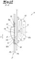
- the swivel hook latch 4 has a base section 4a pivotally attached to a lock housing 10 with the swivel axis 9 and an L-shaped hook section 4b connected to the base section 4a and projecting from the lock housing 10 in the locking position. In a normal position, the hook section 4b engages behind the locking bar 7 or its rear side by a predetermined amount, which represents the overlap of the hook section 4b with the locking bar 7.
- a locking plate 11 being movably attached to the locking bar 7, wherein the locking plate 11 can be moved along the longitudinal direction X of the locking bar 7.
- this locking plate 11 sinks downwards due to gravity until it reaches a lower basic position due to a stop (not shown in detail), in which the passage opening 8 of the locking bar 7 is partially covered in the upper area. This increases the area that the swivel hook latch 4 or its L-shaped hook section 4b can grip behind in the locking position, so that the security against manipulation is increased.
- this locking plate 11 can be lifted against gravity from the basic position by the swivel hook bolt 4 when it is swiveled in - if necessary due to positioning.
- the swiveling in of the swivel hook bolt 4 is therefore not impaired by this movable locking plate 11. In any case, this way it is possible for the swivel hook bolt 4 to engage behind the lowered locking plate 11 in the locking point.
- the locking plate 11 is attached to the back of the locking bar 7 and the swivel hook bolt 4 engages behind the back of the locking plate 11 in the locking position.
- the locking plate 11 preferably has an opening 12 which in the basic position is only partially aligned with the passage opening 8 of the locking bar 7 and which is delimited by an upper actuating edge 13 against which the swivel hook bolt 4 can work during the pivoting in process while raising the locking plate 11.
- This upper actuating edge 13 of the locking plate 11 can be lifted by an inner actuating surface 4c of the hook section 4b of the swivel hook bolt 4.
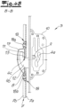
- FIGS. 2 and 3 show a device not according to the invention, in which the rear locking plate 11 is slidably attached to the locking bar 7 together with a front holding plate 14.
- the locking plate 11 and the holding plate 14 are connected to one another at a distance from one another with the locking bar 7 interposed, preferably with the interposition of one or more spacer elements or guide plates 15, which are guided in the passage opening of the locking bar to guide the locking plate 11.
- the spacer elements or guide plates 15 can be designed to be somewhat thicker than the locking bar or its base plate 7a, so that the locking plate 11 and the holding plate 14 are arranged with sufficient spacing and consequently with play, so that the locking plate can easily sink into the basic position due to gravity and can easily be raised against gravity with the swivel hook latch 4.
- the locking plate 11 and the holding plate 14 can be connected to one another by means of one or more screws 16 or similar connecting means with the interposition of the spacer elements 15.
- Figure 3 it is indicated that the opening 12 of the locking plate 11 and/or the opening in the holding plate 14 and/or the through-opening 8 of the locking strip 7 does not have to be rectangular and in particular does not have to have straight side edges. Rather, an embodiment not according to the invention is shown in which one or both side edges are curved in such a way that, for example, the opening 12 in the middle area (in relation to the height) has a greater width than in the upper area and/or lower area.
- This configuration can relate to the opening in the locking plate and/or the through-opening 8 of the locking strip and/or the holding plate 14, which also has an opening.
- the pivoting in of the pivot bolt can be optimized by one or more curved side edges and at the same time there is the possibility that the pivot hook bolt gently pulls the door against the door frame or into the lock as it pivots in, as the pivot hook bolt slides along the curved side edge of the through-opening or opening.
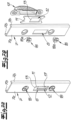
- FIGs 4a , b , 5a , b and 6 as well as 7a,7b A device according to the invention is shown.
- the Figures 4a and 5a show a first functional position with the lock open and consequently the swivel hook bolt not swung out.
- the Figures 4b and 5b show the locking position with the swivel hook bolt swung out, ie the swivel hook bolt passes through the opening 8 of the locking bar 7.
- Figure 7a shows the locking bar in the functional position Figure 4a , 5a in a perspective view.
- Figure 7b shows the locking bar Figure 7a in an exploded view.
- a bolt receiving cup 17 is attached to the back of the locking bar 7 in a generally known manner.
- the swivel hook bolt 4 or its end hook section 4b engages in this bolt receiving cup 17 in the locking position.
- a bolt receiving cup 17 is intended, among other things, to prevent manipulation in the Avoid locking position.
- the locking plate 11 according to the invention is guided so as to be displaceable along the longitudinal direction X - between the locking bar 7 (or the back of the locking bar) and the bolt receiving cup 17.
- the locking bar is preferably U-shaped in cross-section with a base plate 7a forming the U-base and two side legs 7b connected to the base plate and forming the U-legs.
- the locking plate can be dimensioned so that it is guided on the back of the base plate 7a and between the side legs 7b.
- the locking plate 11 is, however, guided on the bolt receiving cup with suitable means along the longitudinal direction X. Overall, the locking plate can be guided very simply and at the same time perfectly along the longitudinal direction X.
- the bolt receiving cup 17 is preferably attached to the locking bar 7 so that it can be adjusted in a transverse direction Y, in such a way that the position of the locking plate itself is not affected.
- the bolt receiving cup 17 is attached to the locking bar with several adjusting elements 18, whereby these adjusting elements 18 are designed as eccentric adjusting elements.
- the end eccentric bolts 18a act on the bolt receiving cup 17 in such a way that it is displaced in the transverse direction Y. In this way, the bolt receiving cup 17 can be perfectly adjusted in the transverse direction Y.
- the locking plate 7 is attached to the locking bar in such a way that the lowering into the basic position is limited, e.g. via a suitable stop. This ensures that the locking plate protrudes into the passage opening by a predetermined dimension M and thus reduces the length of the passage opening by a dimension M of e.g. 5 mm to 10 mm.
- the figures show an example of an embodiment in which the swivel hook bolt 4 passes through the opening 8 of the locking bar 7 from below.
- the locking plate 11 sinks into the lower basic position by gravity. This can optionally be supported by the force of an additional actuating spring.
- the swivel hook bolt 4 lifts the locking plate 11 during the pivoting in process, as the swivel hook bolt works on the upper actuating edge 13 of the opening 12.
- the invention can equally be implemented in locking systems in which the swivel hook bolt 4 is swiveled in the opposite orientation into the area of the locking bar, i.e. the swivel hook bolt is swiveled from above through the passage opening.
- the locking plate 11 is subjected to a suitable force in the opposite direction and thus against gravity, e.g. with an actuating spring which raises the locking plate to the basic position.
- the swivel hook swiveling in from above can lower the locking plate against the force of the actuating spring, e.g. by working against a lower actuating edge of the passage opening.
- Such an embodiment is not shown. However, all options shown in the figures also relate accordingly to such an embodiment.
- a swivel hook latch is shown as an example only, which can be swivelled around a (fixed) axis.
- the term swivel hook latch also covers embodiments in which the swivel hook latch is not pivoted about a fixed axis, but moves, for example, on an arcuate path in the manner of a pivoting movement. Details are not shown in the figures.
Landscapes
- Lock And Its Accessories (AREA)
Claims (11)
- Dispositif récepteur de verrou, destiné à un système de fermeture (1) comportant au moins un verrou à bascule (4),pourvu d'une barrette de fermeture (7), qui comporte un orifice de passage (8) pour un verrou à bascule (4),sur la barrette de fermeture (7) étant placée de manière mobile une plaque de blocage (11), qui est déplaçable le long de la direction longitudinale (X) de la barrette de fermeture (7),la plaque de blocage (11) étant mobile dans une position de base recouvrant partiellement l'orifice de passage (8) et au cours du pivotement du verrou à bascule (4), étant mobile sous l'effet du verrou à bascule hors de la position de base,la plaque de blocage (11) étant fixée par la face arrière sur la barrette de fermeture (7) et dans la position de verrouillage, le verrou à bascule (4) s'engageant par l'arrière dans la face arrière de la plaque de blocage (11),caractérisé en ce quesur la face arrière de la barrette de fermeture (7) est fixé un boîtier récepteur de verrou (17), la plaque de blocage (11) étant guidée de manière déplaçable entre la barrette de fermeture (7) et le boîtier de verrou (17).
- Dispositif selon la revendication 1, caractérisé en ce que la plaque de blocage (11) comporte un ajour (12), qui dans la position de base n'est aligné que par endroits avec l'orifice de passage (8) de la barrette de fermeture (7) et / ou qui est délimité par une arête d'actionnement (13), contre laquelle le verrou à bascule (4) peut travailler au cours du pivotement.
- Dispositif selon la revendication 1 ou 2, le verrou à bascule (4) comportant un segment de base (4a) fixé de manière à pouvoir pivoter à l'aide de par exemple un axe de pivotement (9) sur un boîtier de serrure (10) et un segment en crochet (4b) raccordé sur le segment de base (4a) et saillant hors du boîtier de serrure (10) dans la position de verrouillage, caractérisé en ce que l'arête d'actionnement (13) de la plaque de blocage (11) est actionnable par une surface d'actionnement (4c) interne du segment en crochet (4b).
- Dispositif selon l'une quelconque des revendications 1 à 3, caractérisé en ce que la plaque de blocage (11) est guidée de manière déplaçable sur le boîtier de verrou (17).
- Dispositif selon l'une quelconque des revendications 1 à 4, caractérisé en ce que dans une direction transversale (Y) de la barrette de fermeture, le boîtier de verrou (17) est fixé de manière ajustable sur la barrette de fermeture.
- Dispositif selon la revendication 5, caractérisé en ce que le boîtier de verrou (17) est fixé à l'aide d'un ou de plusieurs éléments de réglage (18), par exemple des éléments de réglage à excentrique sur la barrette de fermeture.
- Dispositif selon l'une quelconque des revendications 1 à 6, la barrette de fermeture étant conçue en forme de U dans sa section transversale, avec une plaque de base (7a) formant la base du U et deux branches latérales (7b) raccordées sur la plaque de base (7a) et formant les branches latérales du U, caractérisé en ce que la plaque de blocage (11) est guidée par la face arrière sur la plaque de base et de préférence latéralement entre les branches latérales.
- Dispositif selon l'une quelconque des revendications 1 à 7, caractérisé en ce que la plaque de blocage (11) est mobile par une force, par exemple par une force de gravité et / ou par une force élastique dans la position de base.
- Dispositif selon la revendication 8, caractérisé en ce qu'au cours du pivotement, le verrou à bascule (4) peut travailler à travers l'orifice de passage (8) par le bas contre une arête d'actionnement (13) supérieure de la plaque de blocage et soulève à cet effet la plaque de blocage (11) à l'encontre de la force de gravité.
- Dispositif selon la revendication 8, caractérisé en ce qu'au cours du pivotement, le verrou à bascule (4) peut travailler à travers l'orifice de passage (8) par le haut contre une arête d'actionnement inférieure de la plaque de blocage et abaisse à cet effet la plaque de blocage à l'encontre d'une force, par exemple une force élastique.
- Système de fermeture, pourvu d'une serrure susceptible d'être fixée ou fixée sur un battant de porte ou un battant de fenêtre, par exemple une crémone-serrure, qui comporte au moins un verrou à bascule et pourvu d'un dispositif récepteur de verrou selon l'une quelconque des revendications 1 à 10.
Applications Claiming Priority (1)
| Application Number | Priority Date | Filing Date | Title |
|---|---|---|---|
| DE102018118388.7A DE102018118388A1 (de) | 2018-07-30 | 2018-07-30 | Riegelaufnahmevorrichtung |
Publications (3)
| Publication Number | Publication Date |
|---|---|
| EP3640415A1 EP3640415A1 (fr) | 2020-04-22 |
| EP3640415C0 EP3640415C0 (fr) | 2024-12-04 |
| EP3640415B1 true EP3640415B1 (fr) | 2024-12-04 |
Family
ID=66647134
Family Applications (1)
| Application Number | Title | Priority Date | Filing Date |
|---|---|---|---|
| EP19176220.2A Active EP3640415B1 (fr) | 2018-07-30 | 2019-05-23 | Dispositif de gâche |
Country Status (2)
| Country | Link |
|---|---|
| EP (1) | EP3640415B1 (fr) |
| DE (1) | DE102018118388A1 (fr) |
Families Citing this family (1)
| Publication number | Priority date | Publication date | Assignee | Title |
|---|---|---|---|---|
| DE202021100537U1 (de) | 2021-02-03 | 2021-02-16 | Carl Fuhr GmbH & Co. KG. | Schließteilanordnung |
Family Cites Families (3)
| Publication number | Priority date | Publication date | Assignee | Title |
|---|---|---|---|---|
| JPS512137Y2 (fr) * | 1972-02-05 | 1976-01-22 | ||
| JPS542594U (fr) * | 1977-06-03 | 1979-01-09 | ||
| DE102013101033A1 (de) | 2013-02-01 | 2014-08-07 | Carl Fuhr Gmbh & Co. Kg | Riegelaufnahmeteil |
-
2018
- 2018-07-30 DE DE102018118388.7A patent/DE102018118388A1/de active Pending
-
2019
- 2019-05-23 EP EP19176220.2A patent/EP3640415B1/fr active Active
Also Published As
| Publication number | Publication date |
|---|---|
| EP3640415C0 (fr) | 2024-12-04 |
| EP3640415A1 (fr) | 2020-04-22 |
| DE102018118388A1 (de) | 2020-01-30 |
Similar Documents
| Publication | Publication Date | Title |
|---|---|---|
| DE69507825T2 (de) | Verbesserungen an sicherheitsgittern | |
| DE20013512U1 (de) | Sektionalhub- oder Falttor | |
| DE102016119515A1 (de) | Beschlag für eine Schiebetür, Schiebetüreinheit, Verfahren zum Öffnen einer Schiebetür und Verfahren zum Schließen einer Schiebetür | |
| DE69328827T2 (de) | Schiebefenster, bestehend aus mindestens einem rahmen mit einem darin vertikal verschiebbaren flügel | |
| EP3296493B1 (fr) | Système support pour porte coulissante | |
| EP3752700B1 (fr) | Protection anti-effraction abaissable | |
| EP3640415B1 (fr) | Dispositif de gâche | |
| EP0005764A1 (fr) | Porte ou fenêtre coulissante et basculante | |
| EP2113624B1 (fr) | Dispositif de fixation de porte ou de fenêtre | |
| DE10107382A9 (de) | Vorrichtung zur verriegelung, halterung und anpressung von tueren oder fenstern an einem tuer- oder fensterrahmen | |
| DE19637452C2 (de) | Verriegelungsvorrichtung zwischen einem Zargenrahmen und einem im Schließzustand in diesen eingreifenden Torblatt | |
| DE10107382A1 (de) | Vorrichtung zur Verriegelung, Halterung und Anpressung von Türen oder Fenstern an einem Tür- oder Fensterrahmen | |
| DE8216056U1 (de) | Fallen-panikschloss | |
| EP4116529A1 (fr) | Unité de verrouillage | |
| EP2141313B1 (fr) | Dispositif d'arrêt d'un volet | |
| EP1067270B1 (fr) | Dispositif de verrouillage pour un volet d'une ouverture de bâtiment, notamment pour un volet roulant | |
| DE825221C (de) | Schlossfallenverriegelung, insbesondere fuer Kraftfahrzeugtuerschloesser | |
| EP1405974B1 (fr) | Mécanisme de verrouillage pour fenêtre ou porte oscillobattante | |
| DE69201798T2 (de) | Verriegelungsvorrichtung. | |
| EP3818233B1 (fr) | Dispositif pour protection d'une porte contre le cambriolage | |
| EP3511493B1 (fr) | Système de porte coulissante | |
| DE4419779B4 (de) | Türsicherungsvorrichtung | |
| DE935349C (de) | Verschluss- und Feststellvorrichtung von parallelzuruecksetzbaren und anschliessend schwenkbaren Fluegeln von Fenstern, Tueren od. dgl. mit einer Hubvorrichtung | |
| DE69625331T2 (de) | Feststeller für Tür, Fenster oder sonstiges | |
| DE9400745U1 (de) | Treibstangenverschluß für Fenster, Türen o.dgl. |
Legal Events
| Date | Code | Title | Description |
|---|---|---|---|
| PUAI | Public reference made under article 153(3) epc to a published international application that has entered the european phase |
Free format text: ORIGINAL CODE: 0009012 |
|
| STAA | Information on the status of an ep patent application or granted ep patent |
Free format text: STATUS: THE APPLICATION HAS BEEN PUBLISHED |
|
| AK | Designated contracting states |
Kind code of ref document: A1 Designated state(s): AL AT BE BG CH CY CZ DE DK EE ES FI FR GB GR HR HU IE IS IT LI LT LU LV MC MK MT NL NO PL PT RO RS SE SI SK SM TR |
|
| AX | Request for extension of the european patent |
Extension state: BA ME |
|
| STAA | Information on the status of an ep patent application or granted ep patent |
Free format text: STATUS: REQUEST FOR EXAMINATION WAS MADE |
|
| 17P | Request for examination filed |
Effective date: 20201016 |
|
| RBV | Designated contracting states (corrected) |
Designated state(s): AL AT BE BG CH CY CZ DE DK EE ES FI FR GB GR HR HU IE IS IT LI LT LU LV MC MK MT NL NO PL PT RO RS SE SI SK SM TR |
|
| STAA | Information on the status of an ep patent application or granted ep patent |
Free format text: STATUS: EXAMINATION IS IN PROGRESS |
|
| 17Q | First examination report despatched |
Effective date: 20210721 |
|
| RIC1 | Information provided on ipc code assigned before grant |
Ipc: E05C 9/18 20060101ALN20240725BHEP Ipc: E05B 15/02 20060101AFI20240725BHEP |
|
| GRAP | Despatch of communication of intention to grant a patent |
Free format text: ORIGINAL CODE: EPIDOSNIGR1 |
|
| STAA | Information on the status of an ep patent application or granted ep patent |
Free format text: STATUS: GRANT OF PATENT IS INTENDED |
|
| GRAS | Grant fee paid |
Free format text: ORIGINAL CODE: EPIDOSNIGR3 |
|
| INTG | Intention to grant announced |
Effective date: 20240905 |
|
| GRAA | (expected) grant |
Free format text: ORIGINAL CODE: 0009210 |
|
| STAA | Information on the status of an ep patent application or granted ep patent |
Free format text: STATUS: THE PATENT HAS BEEN GRANTED |
|
| AK | Designated contracting states |
Kind code of ref document: B1 Designated state(s): AL AT BE BG CH CY CZ DE DK EE ES FI FR GB GR HR HU IE IS IT LI LT LU LV MC MK MT NL NO PL PT RO RS SE SI SK SM TR |
|
| REG | Reference to a national code |
Ref country code: GB Ref legal event code: FG4D Free format text: NOT ENGLISH |
|
| REG | Reference to a national code |
Ref country code: CH Ref legal event code: EP |
|
| REG | Reference to a national code |
Ref country code: DE Ref legal event code: R096 Ref document number: 502019012580 Country of ref document: DE |
|
| REG | Reference to a national code |
Ref country code: IE Ref legal event code: FG4D Free format text: LANGUAGE OF EP DOCUMENT: GERMAN |
|
| U01 | Request for unitary effect filed |
Effective date: 20241219 |
|
| U07 | Unitary effect registered |
Designated state(s): AT BE BG DE DK EE FI FR IT LT LU LV MT NL PT RO SE SI Effective date: 20250110 |
|
| PG25 | Lapsed in a contracting state [announced via postgrant information from national office to epo] |
Ref country code: HR Free format text: LAPSE BECAUSE OF FAILURE TO SUBMIT A TRANSLATION OF THE DESCRIPTION OR TO PAY THE FEE WITHIN THE PRESCRIBED TIME-LIMIT Effective date: 20241204 |
|
| PG25 | Lapsed in a contracting state [announced via postgrant information from national office to epo] |
Ref country code: ES Free format text: LAPSE BECAUSE OF FAILURE TO SUBMIT A TRANSLATION OF THE DESCRIPTION OR TO PAY THE FEE WITHIN THE PRESCRIBED TIME-LIMIT Effective date: 20241204 |
|
| PG25 | Lapsed in a contracting state [announced via postgrant information from national office to epo] |
Ref country code: NO Free format text: LAPSE BECAUSE OF FAILURE TO SUBMIT A TRANSLATION OF THE DESCRIPTION OR TO PAY THE FEE WITHIN THE PRESCRIBED TIME-LIMIT Effective date: 20250304 |
|
| PG25 | Lapsed in a contracting state [announced via postgrant information from national office to epo] |
Ref country code: GR Free format text: LAPSE BECAUSE OF FAILURE TO SUBMIT A TRANSLATION OF THE DESCRIPTION OR TO PAY THE FEE WITHIN THE PRESCRIBED TIME-LIMIT Effective date: 20250305 |
|
| PG25 | Lapsed in a contracting state [announced via postgrant information from national office to epo] |
Ref country code: RS Free format text: LAPSE BECAUSE OF FAILURE TO SUBMIT A TRANSLATION OF THE DESCRIPTION OR TO PAY THE FEE WITHIN THE PRESCRIBED TIME-LIMIT Effective date: 20250304 |
|
| U20 | Renewal fee for the european patent with unitary effect paid |
Year of fee payment: 7 Effective date: 20250411 |
|
| PG25 | Lapsed in a contracting state [announced via postgrant information from national office to epo] |
Ref country code: SM Free format text: LAPSE BECAUSE OF FAILURE TO SUBMIT A TRANSLATION OF THE DESCRIPTION OR TO PAY THE FEE WITHIN THE PRESCRIBED TIME-LIMIT Effective date: 20241204 |
|
| PG25 | Lapsed in a contracting state [announced via postgrant information from national office to epo] |
Ref country code: PL Free format text: LAPSE BECAUSE OF FAILURE TO SUBMIT A TRANSLATION OF THE DESCRIPTION OR TO PAY THE FEE WITHIN THE PRESCRIBED TIME-LIMIT Effective date: 20241204 |
|
| PG25 | Lapsed in a contracting state [announced via postgrant information from national office to epo] |
Ref country code: IS Free format text: LAPSE BECAUSE OF FAILURE TO SUBMIT A TRANSLATION OF THE DESCRIPTION OR TO PAY THE FEE WITHIN THE PRESCRIBED TIME-LIMIT Effective date: 20250404 |
|
| PG25 | Lapsed in a contracting state [announced via postgrant information from national office to epo] |
Ref country code: SK Free format text: LAPSE BECAUSE OF FAILURE TO SUBMIT A TRANSLATION OF THE DESCRIPTION OR TO PAY THE FEE WITHIN THE PRESCRIBED TIME-LIMIT Effective date: 20241204 |
|
| PG25 | Lapsed in a contracting state [announced via postgrant information from national office to epo] |
Ref country code: CZ Free format text: LAPSE BECAUSE OF FAILURE TO SUBMIT A TRANSLATION OF THE DESCRIPTION OR TO PAY THE FEE WITHIN THE PRESCRIBED TIME-LIMIT Effective date: 20241204 |
|
| PLBE | No opposition filed within time limit |
Free format text: ORIGINAL CODE: 0009261 |
|
| STAA | Information on the status of an ep patent application or granted ep patent |
Free format text: STATUS: NO OPPOSITION FILED WITHIN TIME LIMIT |
|
| REG | Reference to a national code |
Ref country code: CH Ref legal event code: L10 Free format text: ST27 STATUS EVENT CODE: U-0-0-L10-L00 (AS PROVIDED BY THE NATIONAL OFFICE) Effective date: 20251015 |
|
| 26N | No opposition filed |
Effective date: 20250905 |
|
| REG | Reference to a national code |
Ref country code: CH Ref legal event code: H13 Free format text: ST27 STATUS EVENT CODE: U-0-0-H10-H13 (AS PROVIDED BY THE NATIONAL OFFICE) Effective date: 20251223 |
|
| PG25 | Lapsed in a contracting state [announced via postgrant information from national office to epo] |
Ref country code: CH Free format text: LAPSE BECAUSE OF NON-PAYMENT OF DUE FEES Effective date: 20250531 |
|
| GBPC | Gb: european patent ceased through non-payment of renewal fee |
Effective date: 20250523 |
|
| PG25 | Lapsed in a contracting state [announced via postgrant information from national office to epo] |
Ref country code: MC Free format text: LAPSE BECAUSE OF FAILURE TO SUBMIT A TRANSLATION OF THE DESCRIPTION OR TO PAY THE FEE WITHIN THE PRESCRIBED TIME-LIMIT Effective date: 20241204 |
|
| PG25 | Lapsed in a contracting state [announced via postgrant information from national office to epo] |
Ref country code: GB Free format text: LAPSE BECAUSE OF NON-PAYMENT OF DUE FEES Effective date: 20250523 |
|
| PG25 | Lapsed in a contracting state [announced via postgrant information from national office to epo] |
Ref country code: IE Free format text: LAPSE BECAUSE OF NON-PAYMENT OF DUE FEES Effective date: 20250523 |