EP3640434A2 - Hybride rotorscheibenanordnung mit keramischer matrix-verbundstoff-plattform für einen gasturbinenmotor - Google Patents
Hybride rotorscheibenanordnung mit keramischer matrix-verbundstoff-plattform für einen gasturbinenmotor Download PDFInfo
- Publication number
- EP3640434A2 EP3640434A2 EP19196577.1A EP19196577A EP3640434A2 EP 3640434 A2 EP3640434 A2 EP 3640434A2 EP 19196577 A EP19196577 A EP 19196577A EP 3640434 A2 EP3640434 A2 EP 3640434A2
- Authority
- EP
- European Patent Office
- Prior art keywords
- cmc
- platform
- airfoil
- defines
- assembly
- Prior art date
- Legal status (The legal status is an assumption and is not a legal conclusion. Google has not performed a legal analysis and makes no representation as to the accuracy of the status listed.)
- Granted
Links
Images





Classifications
-
- F—MECHANICAL ENGINEERING; LIGHTING; HEATING; WEAPONS; BLASTING
- F01—MACHINES OR ENGINES IN GENERAL; ENGINE PLANTS IN GENERAL; STEAM ENGINES
- F01D—NON-POSITIVE DISPLACEMENT MACHINES OR ENGINES, e.g. STEAM TURBINES
- F01D25/00—Component parts, details, or accessories, not provided for in, or of interest apart from, other groups
- F01D25/24—Casings; Casing parts, e.g. diaphragms, casing fastenings
- F01D25/246—Fastening of diaphragms or stator-rings
-
- F—MECHANICAL ENGINEERING; LIGHTING; HEATING; WEAPONS; BLASTING
- F01—MACHINES OR ENGINES IN GENERAL; ENGINE PLANTS IN GENERAL; STEAM ENGINES
- F01D—NON-POSITIVE DISPLACEMENT MACHINES OR ENGINES, e.g. STEAM TURBINES
- F01D11/00—Preventing or minimising internal leakage of working-fluid, e.g. between stages
- F01D11/005—Sealing means between non relatively rotating elements
- F01D11/006—Sealing the gap between rotor blades or blades and rotor
- F01D11/008—Sealing the gap between rotor blades or blades and rotor by spacer elements between the blades, e.g. independent interblade platforms
-
- F—MECHANICAL ENGINEERING; LIGHTING; HEATING; WEAPONS; BLASTING
- F01—MACHINES OR ENGINES IN GENERAL; ENGINE PLANTS IN GENERAL; STEAM ENGINES
- F01D—NON-POSITIVE DISPLACEMENT MACHINES OR ENGINES, e.g. STEAM TURBINES
- F01D5/00—Blades; Blade-carrying members; Heating, heat-insulating, cooling or antivibration means on the blades or the members
- F01D5/12—Blades
- F01D5/14—Form or construction
- F01D5/147—Construction, i.e. structural features, e.g. of weight-saving hollow blades
-
- F—MECHANICAL ENGINEERING; LIGHTING; HEATING; WEAPONS; BLASTING
- F01—MACHINES OR ENGINES IN GENERAL; ENGINE PLANTS IN GENERAL; STEAM ENGINES
- F01D—NON-POSITIVE DISPLACEMENT MACHINES OR ENGINES, e.g. STEAM TURBINES
- F01D5/00—Blades; Blade-carrying members; Heating, heat-insulating, cooling or antivibration means on the blades or the members
- F01D5/12—Blades
- F01D5/22—Blade-to-blade connections, e.g. for damping vibrations
- F01D5/225—Blade-to-blade connections, e.g. for damping vibrations by shrouding
-
- F—MECHANICAL ENGINEERING; LIGHTING; HEATING; WEAPONS; BLASTING
- F01—MACHINES OR ENGINES IN GENERAL; ENGINE PLANTS IN GENERAL; STEAM ENGINES
- F01D—NON-POSITIVE DISPLACEMENT MACHINES OR ENGINES, e.g. STEAM TURBINES
- F01D5/00—Blades; Blade-carrying members; Heating, heat-insulating, cooling or antivibration means on the blades or the members
- F01D5/12—Blades
- F01D5/28—Selecting particular materials; Particular measures relating thereto; Measures against erosion or corrosion
- F01D5/282—Selecting composite materials, e.g. blades with reinforcing filaments
-
- F—MECHANICAL ENGINEERING; LIGHTING; HEATING; WEAPONS; BLASTING
- F01—MACHINES OR ENGINES IN GENERAL; ENGINE PLANTS IN GENERAL; STEAM ENGINES
- F01D—NON-POSITIVE DISPLACEMENT MACHINES OR ENGINES, e.g. STEAM TURBINES
- F01D5/00—Blades; Blade-carrying members; Heating, heat-insulating, cooling or antivibration means on the blades or the members
- F01D5/12—Blades
- F01D5/28—Selecting particular materials; Particular measures relating thereto; Measures against erosion or corrosion
- F01D5/284—Selection of ceramic materials
-
- F—MECHANICAL ENGINEERING; LIGHTING; HEATING; WEAPONS; BLASTING
- F05—INDEXING SCHEMES RELATING TO ENGINES OR PUMPS IN VARIOUS SUBCLASSES OF CLASSES F01-F04
- F05D—INDEXING SCHEME FOR ASPECTS RELATING TO NON-POSITIVE-DISPLACEMENT MACHINES OR ENGINES, GAS-TURBINES OR JET-PROPULSION PLANTS
- F05D2300/00—Materials; Properties thereof
- F05D2300/60—Properties or characteristics given to material by treatment or manufacturing
- F05D2300/603—Composites; e.g. fibre-reinforced
- F05D2300/6033—Ceramic matrix composites [CMC]
Definitions
- the present disclosure relates to a gas turbine engine, and more particularly to Ceramic Matrix Composites (CMC) components therefor.
- CMC Ceramic Matrix Composites
- Turbine rotor modules often include a multiple of rotor disks that may be fastened together by bolts, tie rods and other structures. Each of the rotor disks includes a multiple of shrouded blades which are typically retained through a firtree slot arrangement. This approach works well with metal alloys, but may be a challenge when the rotor disk is manufactured of a ceramic matrix composite (CMC) material.
- CMC ceramic matrix composite
- a Ceramic Matrix Composite (CMC) platform assembly for an airfoil of a gas turbine engine includes a CMC platform segment which at least partially defines an airfoil profile.
- a Ceramic Matrix Composite (CMC) platform assembly for an airfoil of a gas turbine engine includes a CMC forward platform segment with a first platform inner surface which at least partially defines an airfoil profile and a CMC aft platform segment with a second platform inner surface which defines a remainder of the airfoil profile.
- CMC Ceramic Matrix Composite
- a Ceramic Matrix Composite (CMC) platform assembly for an airfoil of a gas turbine engine includes a CMC platform segment which defines a first edge surface countered to abut a pressure side of a first airfoil and a second edge surface countered to abut a suction side of a second airfoil.
- a rotor disk assembly for a gas turbine engine includes a hub defined about an axis of rotation, the hub includes a first radial flange having a multiple of first apertures and a second radial flange with a multiple of second apertures.
- a CMC platform segment at least partially contoured to the CMC airfoil, the CMC platform segment defines an at least partial platform aperture.
- An airfoil pin is engaged with the at least partial platform aperture, the one of the multiple of first and second apertures and the bore.
- FIG. 1 schematically illustrates a gas turbine engine 20.
- the gas turbine engine 20 is disclosed herein as a two-spool turbofan that generally incorporates a fan section 22, a compressor section 24, a combustor section 26 and a turbine section 28.
- Alternative engines might include an augmentor section (not shown) among other systems or features.
- the fan section 22 drives air along a bypass flowpath while the compressor section 24 drives air along a core flowpath for compression and communication into the combustor section 26 then expansion through the turbine section 28.
- FIG. 1 schematically illustrates a gas turbine engine 20.
- the gas turbine engine 20 is disclosed herein as a two-spool turbofan that generally incorporates a fan section 22, a compressor section 24, a combustor section 26 and a turbine section 28.
- Alternative engines might include an augmentor section (not shown) among other systems or features.
- the fan section 22 drives air along a bypass flowpath while the compressor section 24 drives air along a core flowpath for compression and communication into the combustor section 26
- the engine 20 generally includes a low speed spool 30 and a high speed spool 32 mounted for rotation about an engine central longitudinal axis A relative to an engine static structure 36 via several bearing systems 38. It should be understood that various bearing systems 38 at various locations may alternatively or additionally be provided.
- the low speed spool 30 generally includes an inner shaft 40 that interconnects a fan 42, a low pressure compressor 44 and a low pressure turbine 46.
- the inner shaft 40 is connected to the fan 42 through a geared architecture 48 to drive the fan 42 at a lower speed than the low speed spool 30.
- the high speed spool 32 includes an outer shaft 50 that interconnects a high pressure compressor 52 and high pressure turbine 54.
- a combustor 56 is arranged between the high pressure compressor 52 and the high pressure turbine 54.
- the inner shaft 40 and the outer shaft 50 are concentric and rotate about the engine central longitudinal axis A which is collinear with their longitudinal axes.
- the core airflow is compressed by the low pressure compressor 44 then the high pressure compressor 52, mixed with fuel and burned in the combustor 56, then expanded over the high pressure turbine 54 and low pressure turbine 46.
- the turbines 54, 46 rotationally drive the respective low speed spool 30 and high speed spool 32 in response to the expansion.
- the low pressure turbine 46 generally includes a low pressure turbine case 60 with a multiple of low pressure turbine stages.
- the low pressure turbine case 60 is manufactured of a ceramic matrix composite (CMC) material or metal alloy.
- CMC material for all componentry discussed herein may include, but are not limited to, for example, S200 and SiC/SiC.
- metal superalloy for all componentry discussed herein may include, but are not limited to, for example, INCO 718 and Waspaloy.
- low pressure turbine Although depicted as a low pressure turbine in the disclosed embodiment, it should be understood that the concepts described herein are not limited to use with low pressure turbine as the teachings may be applied to other sections such as high pressure turbine, high pressure compressor, low pressure compressor and intermediate pressure compressor and intermediate pressure turbine of a three-spool architecture gas turbine engine.
- a low pressure turbine (LPT) rotor module 62 includes a multiple (three shown) of CMC disk assemblies 64A, 64B, 64C.
- Each of the CMC disk assemblies 64A, 64B, 64C include a row of airfoils 66A, 66B, 66C which extend from a respective hub 68A, 68B, 68C.
- the rows of airfoils 66A, 66B, 66C are interspersed with CMC vane structures 70A, 70B to form a respective number of LPT stages. It should be understood that any number of stages may be provided.
- the CMC disk assemblies 64A, 64C include arms 72A, 72C which extend from the respective hub 68A, 68C.
- the arms 72A, 72C trap a mount 74B which extends from hub 68B.
- a multiple of fasteners 76 (only one shown) mount the arms 72A, 72C to the mount 74B to assemble the CMC disk assemblies 64A, 64B, 64C and form the LPT rotor module 62.
- the radially inwardly extending mount 74B collectively attaches the LPT rotor module 62 to the inner shaft 40.
- the arms 72A, 72C may also include seals such as knife edge seals 71 which interface with the CMC vane structures 70A, 70B.
- Each hub 68A, 68B, 68C further includes a bore geometrically that generally includes a blade mount section 78A, 78B, 78C, a relatively thin disk section 80A, 80B, 80C that extends radially inward from the respective blade mount section 78A, 78B, 78C then flares axially outward to define a bore section 82A, 82B, 82C.
- the hub 68A, 68B, 68C may be manufactured of CMC materials, such as S200 and SiC/SiC, or metal alloy materials and others to provide a hybrid rotor disk assembly.
- the bore 82A, 82B, 82C facilitates the balance of hoop stresses by minimizing free ring growth and to counter moments which cause airfoil roll that may otherwise increase stresses. That is, bore 82A, 82B, 82C is designed to counter balance the load related to the respective rows of airfoils 66A, 66B, 66C and appendages such as the hub 72A, 72C. Placement of appendages such as the hub 72A, 72C is typically placed in the self sustaining radius.
- the self sustaining radius is defined herein as the radius where the radial growth of the disk equals the radial growth of a free spinning ring.
- Mass radially inboard of the self sustaining radius is load carrying and mass radially outboard of the self-sustaining radius is not load carrying and can not support itself.
- the relatively thin disk sections 80A, 80B, 80C and the bore sections 82A, 82B, 82C may otherwise be of various forms and geometries.
- rotor disk assembly 64C will be described in detail herein as the hybrid rotor disk assembly, such description may also be applicable to CMC disk assemblies 64A, 64B as well as additional or other stages.
- the LPT rotor module 62 may include only one or any number of hybrid CMC disk assemblies such as disk assembly 64C combined with other disk constructions. It should also be understood that other rotor modules will also benefit herefrom.
- the CMC disk assembly 64C generally includes the hub 68C, a multiple of airfoils 66C with a respective airfoil pin 84 (only one of each shown), a forward platform segment 86 and an aft platform segment 88.
- a hybrid combination of materials may be utilized within the disk assembly 64C.
- the hub 68C may be manufactured of INCO718, Waspaloy, or other metal alloy
- the airfoils 66C and the platform segments 86, 88 may be manufactured of a CMC material
- the airfoil pin 84 may be manufactured of a Waspaloy material. It should be understood that various other materials and combinations thereof may alternatively be utilized.
- the blade mount section 78C of the hub 68C defines a first radial flange 90 and a second radial flange 92 which receive a root section 66Cr of each of the multiple of airfoils 66C therebetween.
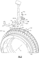
- Each of the first radial flange 90 and the second radial flange 92 define a respective multiple of apertures 90A, 92A which form paired sets that align and correspond with a bore 66CrB defined by the root section 66Cr of the airfoil 66C ( Figure 4 ).
- An aperture 86A, 88A within a flange 86F, 88F of each respective platform segment 86, 88 align with the associated aperture 90A, 92A.
- each flange 86E, 86F, 88F of each respective platform segments 86, 88 at least partially encloses the first radial flange 90 and the second radial flange 92 such that the assembled platform segments 86, 88 define the inner core airflow gas path C ( Figure 5 ).
- the apertures 86A, 88A, 90A, 92A, and bore 66CrB form a curved path defined by a non-linear axis C with respect to the engine longitudinal axis A about which hub 68C rotates.
- the airfoil pin 84 extends along the non-linear axis C such that the airfoil pin 84 is readily assembled along the curved path.
- the curved path in one disclosed non-limiting embodiment, generally matches the chamber 66cC of the airfoil 66C such that centrifugal and aerodynamic forces pass radially through the pin 84 ( Figure 6 ).
- the cross-sectional shape of the airfoil pin 84 matches the bore 66CrB.
- the bore 66CrB in the disclosed non-limiting embodiment is non-circular in cross-section to maximize engagement as well as prevent roll of the airfoil 66C.
- the airfoil pin 84 and the bore 66CrB is of a race track cross-sectional shape.
- the airfoil pin 84 is held in place along non-linear axis C with, for example, a head 84H on one end and a fastener 98 engaged with an opposite end. It should be understood that various alternate or additional retention systems may be provided.
- each airfoil 66C generally includes a CMC root section 66Cr, a CMC airfoil section 66Ca and a CMC tip section 66Ct. It should be understood that although described with respect to discrete sections 66Cr, 66Ca, 66Ct, the airfoil 66C is essentially an integral CMC component formed from CMC ply layers which extend between the sections.
- the airfoil section 66Ca defines a generally concave shaped side which forms a pressure side 66P and a generally convex shaped side which forms a suction side 66S between a leading edge 66CL and a trailing edge 66CT.
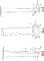
- the root section 66Cr defines the bore 66CrB along the non-linear axis C and blends into the airfoil section 66Ca. That is, the non-linear axis C defines a curve, bend, angle or other non-linear path which may generally follow the chamber of the airfoil section 66Ca ( Figures 8 and 9 ).
- the bore 66CrB extends through the root section 66Cr generally between the leading edge 66CL and a trailing edge 66CT to attach the airfoil 66C to the hub 68C.
- the fabrication of the CMC airfoil 66 may be performed in several steps to form the various features.
- the root section 66Cr may be manufactured from a tube 100 of CMC material such that the tube 100 defines the bore 66CrB along the non-linear axis C.
- tube as defined herein includes, but is not limited to, a non-circular member in cross-section. Additional CMC plies 102 of CMC material wrap around the tube 100 then extend along an airfoil axis B to form the airfoil section 66Ca and the tip section 66Ct in an integral manner.
- the tip section 66Ct may define a platform section which, when assembled adjacent to the multiple of airfoils 66C, defines an outer shroud. That is, the tip section 66Ct is includes a cap of CMC plies 104 which are generally transverse to the airfoil axis B.
- the cap of CMC plies 104 may alternatively or additionally include fabric plies to obtain thicker sections if required.
- Triangular areas 106, 108 at which the multiple of CMC plies 102 separate to at least partially surround the tube 100 and separate to form the tip section 66Ct may be filled with a CMC filler material 110 such as chopped fiber and a tackifier.
- the CMC filler material 110 may additionally be utilized in areas where pockets or lack of material may exist without compromising structural integrity.
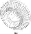
- the forward platform segment 86 and the aft platform segment 88 are assembled with the airfoil pin 84 to provide a platform assembly ( Figure 12 ) that axially traps each of the airfoils 66C therebetween.
- a platform inner surface 86S, 88S of the respective platform segment 86, 88 defines an airfoil profile to fit closely around the surface of each airfoil 66C to thereby enclose the space between the first and second radial flange 90, 92 to prevent the entrance of core airflow ( Figure 12 ).
- the forward platform segment 86 and the aft platform segment 88 further define a contoured edge structure 86E, 88E such that each adjacent set of platform segments 86, 88 seal with the adjacent set of platform segments 86, 88 ( Figure 12 ). It should be understood that further redundant seal structures such as feather seals may alternatively or additionally be provided.
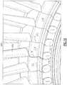
- another non-limiting embodiment includes a platform 114 which is arranged to fit between each airfoil 66 ( Figure 16 ).
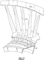
- the platform 114 includes a first edge surface 116 which abuts the pressure side 66P of one airfoil 66 and a second edge surface 118 which abuts a suction side 66S of an adjacent different airfoil 66 such that the multiple of platforms 114 enclose the space between the first and second radial flange 90, 92 ( Figure 16 ) to define the inner core airflow gas path ( Figure 17 ).
- Each platform 114 further includes two partial apertures 120, 122 within a respective forward and aft flange 114FF, 114FA such that the platform 114 is trapped by two airfoil pins 84. That is, the head 84H of the airfoil pin 84 bridges adjacent platforms 114. The heads 84H may be located adjacent the aft flange 114FA of the platform 114.
- another CMC disk assembly 64C' generally includes a hub 68C' having a first radial flange 90', a second radial flange 92' and a third radial flange 91' to define a blade mount section 78C'.
- the third radial flange 91' facilitates additional support for the airfoil pin 84'.
- the hub 68C' generally includes the blade mount section 78C', a relatively thin disk section 80C' that extends radially inward from the blade mount section 78C' and an outwardly flared bore section 82C'.
- the third radial flange 91' in the disclosed non-limiting embodiment is located generally in line with the relatively thin disk section 80C' as well as a bend formed within the root section 66Cr'.
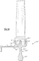
- the root section 66Cr' includes a slot 124 (also illustrated in Figure 19 ) which receives the third radial flange 91'.
- the slot 124 also facilitates relief of any potential stress build up during CMC formation in the bend of the root section 66Cr'. It should be understood that the remainder of assembly is generally as described above.
- the hybrid assembly defined by the use of metal alloys and CMC materials facilitates a lower weight configuration through the design integration of a CMC blade.
- the lower density of the material translates to a reduced rim pull which decreases the stress field and disk weight.
Landscapes
- Engineering & Computer Science (AREA)
- Mechanical Engineering (AREA)
- General Engineering & Computer Science (AREA)
- Chemical & Material Sciences (AREA)
- Materials Engineering (AREA)
- Architecture (AREA)
- Composite Materials (AREA)
- Ceramic Engineering (AREA)
- Turbine Rotor Nozzle Sealing (AREA)
- Structures Of Non-Positive Displacement Pumps (AREA)
Applications Claiming Priority (3)
| Application Number | Priority Date | Filing Date | Title |
|---|---|---|---|
| US13/116,173 US8936440B2 (en) | 2011-05-26 | 2011-05-26 | Hybrid rotor disk assembly with ceramic matrix composites platform for a gas turbine engine |
| EP17160228.7A EP3208425B1 (de) | 2011-05-26 | 2012-05-24 | Hybride rotorscheibenanordnung mit keramischer matrix-verbundstoff-plattform für einen gasturbinenmotor |
| EP12169221.4A EP2570603B1 (de) | 2011-05-26 | 2012-05-24 | Plattformbauteil aus keramischem Faserverbundwerkstoff für ein Schaufelprofil eines Gasturbinentriebwerks und zugehörige Rotorscheibenanordnung |
Related Parent Applications (2)
| Application Number | Title | Priority Date | Filing Date |
|---|---|---|---|
| EP17160228.7A Division EP3208425B1 (de) | 2011-05-26 | 2012-05-24 | Hybride rotorscheibenanordnung mit keramischer matrix-verbundstoff-plattform für einen gasturbinenmotor |
| EP12169221.4A Division EP2570603B1 (de) | 2011-05-26 | 2012-05-24 | Plattformbauteil aus keramischem Faserverbundwerkstoff für ein Schaufelprofil eines Gasturbinentriebwerks und zugehörige Rotorscheibenanordnung |
Publications (3)
| Publication Number | Publication Date |
|---|---|
| EP3640434A2 true EP3640434A2 (de) | 2020-04-22 |
| EP3640434A3 EP3640434A3 (de) | 2020-07-29 |
| EP3640434B1 EP3640434B1 (de) | 2022-08-31 |
Family
ID=46149261
Family Applications (3)
| Application Number | Title | Priority Date | Filing Date |
|---|---|---|---|
| EP12169221.4A Active EP2570603B1 (de) | 2011-05-26 | 2012-05-24 | Plattformbauteil aus keramischem Faserverbundwerkstoff für ein Schaufelprofil eines Gasturbinentriebwerks und zugehörige Rotorscheibenanordnung |
| EP17160228.7A Active EP3208425B1 (de) | 2011-05-26 | 2012-05-24 | Hybride rotorscheibenanordnung mit keramischer matrix-verbundstoff-plattform für einen gasturbinenmotor |
| EP19196577.1A Active EP3640434B1 (de) | 2011-05-26 | 2012-05-24 | Hybride rotorscheibenanordnung mit keramischer matrix-verbundstoff-plattform für einen gasturbinenmotor |
Family Applications Before (2)
| Application Number | Title | Priority Date | Filing Date |
|---|---|---|---|
| EP12169221.4A Active EP2570603B1 (de) | 2011-05-26 | 2012-05-24 | Plattformbauteil aus keramischem Faserverbundwerkstoff für ein Schaufelprofil eines Gasturbinentriebwerks und zugehörige Rotorscheibenanordnung |
| EP17160228.7A Active EP3208425B1 (de) | 2011-05-26 | 2012-05-24 | Hybride rotorscheibenanordnung mit keramischer matrix-verbundstoff-plattform für einen gasturbinenmotor |
Country Status (2)
| Country | Link |
|---|---|
| US (1) | US8936440B2 (de) |
| EP (3) | EP2570603B1 (de) |
Families Citing this family (32)
| Publication number | Priority date | Publication date | Assignee | Title |
|---|---|---|---|---|
| US9151166B2 (en) * | 2010-06-07 | 2015-10-06 | Rolls-Royce North American Technologies, Inc. | Composite gas turbine engine component |
| US20130011271A1 (en) * | 2011-07-05 | 2013-01-10 | United Technologies Corporation | Ceramic matrix composite components |
| US8967961B2 (en) * | 2011-12-01 | 2015-03-03 | United Technologies Corporation | Ceramic matrix composite airfoil structure with trailing edge support for a gas turbine engine |
| EP2778347A1 (de) * | 2013-03-11 | 2014-09-17 | Siemens Aktiengesellschaft | Rotorschaufelanordnung, Turbomaschine mit einer Rotorschaufelanordnung und Verfahren zum Aufbau einer Rotorschaufelanordnung |
| US10590780B2 (en) * | 2013-04-02 | 2020-03-17 | United Technologies Corporation | Engine component having support with intermediate layer |
| PL2808486T3 (pl) * | 2013-05-27 | 2017-11-30 | MTU Aero Engines AG | Element wyważający do układu łopatek wirujących |
| EP3027853B1 (de) | 2013-07-29 | 2021-05-19 | Raytheon Technologies Corporation | Cmc-schaufelprofilanordnung für gasturbinentriebwerk |
| WO2015073096A2 (en) | 2013-09-13 | 2015-05-21 | United Technologies Corporation | Fan platform |
| US10156151B2 (en) * | 2014-10-23 | 2018-12-18 | Rolls-Royce North American Technologies Inc. | Composite annulus filler |
| FR3037097B1 (fr) * | 2015-06-03 | 2017-06-23 | Snecma | Aube composite comprenant une plateforme munie d'un raidisseur |
| US10982564B2 (en) | 2014-12-15 | 2021-04-20 | General Electric Company | Apparatus and system for ceramic matrix composite attachment |
| US20160169033A1 (en) * | 2014-12-15 | 2016-06-16 | General Electric Company | Apparatus and system for ceramic matrix composite attachment |
| FR3038653B1 (fr) * | 2015-07-08 | 2017-08-04 | Snecma | Assemblage d'une plateforme rapportee d'aube de soufflante sur un disque de soufflante |
| US9976426B2 (en) * | 2015-07-21 | 2018-05-22 | United Technologies Corporation | Fan platform with stiffening feature |
| US20170058916A1 (en) * | 2015-09-01 | 2017-03-02 | United Technologies Corporation | Gas turbine fan fairing platform and method of fairing a root leading edge of a fan blade of a gas turbine engine |
| US10227880B2 (en) * | 2015-11-10 | 2019-03-12 | General Electric Company | Turbine blade attachment mechanism |
| US10710317B2 (en) | 2016-06-16 | 2020-07-14 | Rolls-Royce North American Technologies Inc. | Composite rotatable assembly for an axial-flow compressor |
| US10428661B2 (en) | 2016-10-26 | 2019-10-01 | Roll-Royce North American Technologies Inc. | Turbine wheel assembly with ceramic matrix composite components |
| US10358922B2 (en) | 2016-11-10 | 2019-07-23 | Rolls-Royce Corporation | Turbine wheel with circumferentially-installed inter-blade heat shields |
| US10731487B2 (en) | 2017-02-20 | 2020-08-04 | General Electric Company | Turbine components and methods of manufacturing |
| US10738630B2 (en) * | 2018-02-19 | 2020-08-11 | General Electric Company | Platform apparatus for propulsion rotor |
| US10767498B2 (en) * | 2018-04-03 | 2020-09-08 | Rolls-Royce High Temperature Composites Inc. | Turbine disk with pinned platforms |
| US11466580B2 (en) * | 2018-05-02 | 2022-10-11 | General Electric Company | CMC nozzle with interlocking mechanical joint and fabrication |
| US10677075B2 (en) | 2018-05-04 | 2020-06-09 | General Electric Company | Composite airfoil assembly for an interdigitated rotor |
| US10941665B2 (en) | 2018-05-04 | 2021-03-09 | General Electric Company | Composite airfoil assembly for an interdigitated rotor |
| US10934861B2 (en) * | 2018-09-12 | 2021-03-02 | Rolls-Royce Plc | Turbine wheel assembly with pinned ceramic matrix composite blades |
| US10774653B2 (en) * | 2018-12-11 | 2020-09-15 | Raytheon Technologies Corporation | Composite gas turbine engine component with lattice structure |
| BE1026984B1 (fr) * | 2019-01-18 | 2020-08-25 | Safran Aero Boosters Sa | Ensemble rotatif de turbomachine |
| US11156110B1 (en) | 2020-08-04 | 2021-10-26 | General Electric Company | Rotor assembly for a turbine section of a gas turbine engine |
| US11725519B2 (en) * | 2021-03-01 | 2023-08-15 | Raytheon Technologies Corporation | Platform for an airfoil of a gas turbine engine |
| US11655719B2 (en) | 2021-04-16 | 2023-05-23 | General Electric Company | Airfoil assembly |
| US20240003317A1 (en) * | 2022-06-29 | 2024-01-04 | Whisper Aero Inc. | Propulsor Fan |
Family Cites Families (27)
| Publication number | Priority date | Publication date | Assignee | Title |
|---|---|---|---|---|
| CA619513A (en) * | 1961-05-02 | Orenda Engines Limited | Bladed rotor assembly | |
| US3057767A (en) | 1958-04-01 | 1962-10-09 | Poly Ind Inc | Method of making compressor blades |
| US3487879A (en) | 1967-08-02 | 1970-01-06 | Dowty Rotol Ltd | Blades,suitable for propellers,compressors,fans and the like |
| US3694104A (en) | 1970-10-07 | 1972-09-26 | Garrett Corp | Turbomachinery blade |
| US3801222A (en) * | 1972-02-28 | 1974-04-02 | United Aircraft Corp | Platform for compressor or fan blade |
| US4400915A (en) | 1980-06-02 | 1983-08-30 | United Technologies Corporation | Fixture for restoring a face on the shroud of a rotor blade |
| US5017092A (en) | 1989-10-16 | 1991-05-21 | United Technologies Corporation | Rotor blade retention |
| US5163817A (en) | 1989-10-16 | 1992-11-17 | United Technologies Corporation | Rotor blade retention |
| US5240377A (en) | 1992-02-25 | 1993-08-31 | Williams International Corporation | Composite fan blade |
| US5580219A (en) | 1995-03-06 | 1996-12-03 | Solar Turbines Incorporated | Ceramic blade attachment system |
| US6213719B1 (en) | 1999-07-28 | 2001-04-10 | United Technologies Corporation | Bar wedge preload apparatus for a propeller blade |
| US6422820B1 (en) | 2000-06-30 | 2002-07-23 | General Electric Company | Corner tang fan blade |
| US6457942B1 (en) | 2000-11-27 | 2002-10-01 | General Electric Company | Fan blade retainer |
| US6447250B1 (en) | 2000-11-27 | 2002-09-10 | General Electric Company | Non-integral fan platform |
| US6481971B1 (en) | 2000-11-27 | 2002-11-19 | General Electric Company | Blade spacer |
| US7284958B2 (en) * | 2003-03-22 | 2007-10-23 | Allison Advanced Development Company | Separable blade platform |
| DE10340773A1 (de) | 2003-09-02 | 2005-03-24 | Man Turbomaschinen Ag | Rotor einer Dampf- oder Gasturbine |
| US7094021B2 (en) | 2004-02-02 | 2006-08-22 | General Electric Company | Gas turbine flowpath structure |
| US7306826B2 (en) | 2004-02-23 | 2007-12-11 | General Electric Company | Use of biased fabric to improve properties of SiC/SiC ceramic composites for turbine engine components |
| FR2868807B1 (fr) | 2004-04-09 | 2008-12-05 | Snecma Moteurs Sa | Dispositif d'equilibrage d'une piece en rotation en particulier d'un rotor de turboreacteur |
| US7393182B2 (en) | 2005-05-05 | 2008-07-01 | Florida Turbine Technologies, Inc. | Composite tip shroud ring |
| US7762781B1 (en) | 2007-03-06 | 2010-07-27 | Florida Turbine Technologies, Inc. | Composite blade and platform assembly |
| US7976281B2 (en) * | 2007-05-15 | 2011-07-12 | General Electric Company | Turbine rotor blade and method of assembling the same |
| FR2918106B1 (fr) | 2007-06-27 | 2011-05-06 | Snecma | Dispositif de retenue axiale d'aubes montees sur un disque de rotor de turbomachine. |
| FR2918409B1 (fr) * | 2007-07-05 | 2011-05-27 | Snecma | Partie tournante de turbomachine comprenant des secteurs inter-aubes formant plateforme rapportes fixement sur un disque |
| FR2939129B1 (fr) * | 2008-11-28 | 2014-08-22 | Snecma Propulsion Solide | Aube de turbomachine en materiau composite et procede pour sa fabrication. |
| US8382436B2 (en) * | 2009-01-06 | 2013-02-26 | General Electric Company | Non-integral turbine blade platforms and systems |
-
2011
- 2011-05-26 US US13/116,173 patent/US8936440B2/en active Active
-
2012
- 2012-05-24 EP EP12169221.4A patent/EP2570603B1/de active Active
- 2012-05-24 EP EP17160228.7A patent/EP3208425B1/de active Active
- 2012-05-24 EP EP19196577.1A patent/EP3640434B1/de active Active
Also Published As
| Publication number | Publication date |
|---|---|
| EP3640434B1 (de) | 2022-08-31 |
| US20120301317A1 (en) | 2012-11-29 |
| EP3208425A2 (de) | 2017-08-23 |
| EP2570603B1 (de) | 2017-04-19 |
| EP2570603A2 (de) | 2013-03-20 |
| EP3208425A3 (de) | 2017-11-08 |
| US8936440B2 (en) | 2015-01-20 |
| EP2570603A3 (de) | 2015-06-17 |
| EP3208425B1 (de) | 2019-09-11 |
| EP3640434A3 (de) | 2020-07-29 |
Similar Documents
| Publication | Publication Date | Title |
|---|---|---|
| EP3640434B1 (de) | Hybride rotorscheibenanordnung mit keramischer matrix-verbundstoff-plattform für einen gasturbinenmotor | |
| EP2570609B1 (de) | Bauteil aus keramischem Faserverbundwerkstoff und zugehörige Rotorscheibenanordnung | |
| EP2570598B1 (de) | Rotorscheibenanordnung für ein Gasturbinentriebwerk | |
| US9915154B2 (en) | Ceramic matrix composite airfoil structures for a gas turbine engine | |
| EP2570608B1 (de) | Rotorbaugruppe aus keramischem Faserverbundwerkstoff für ein Gasturbinentriebwerk, zugehörige Turbinenanordnung und Montageverfahren | |
| EP2570601B1 (de) | Rotorscheibe aus keramischem Faserverbundwerkstoff für ein Gasturbinentriebwerk und zugehörige Rotorbaugruppe | |
| US9011085B2 (en) | Ceramic matrix composite continuous “I”-shaped fiber geometry airfoil for a gas turbine engine | |
| US9334743B2 (en) | Ceramic matrix composite airfoil for a gas turbine engine | |
| US10184402B2 (en) | Ceramic matrix composite turbine exhaust case for a gas turbine engine | |
| CN112392551B (zh) | 涡轮机的叶片保持特征 | |
| EP2570605B1 (de) | Rotorscheibe aus keramischem Faserverbundwerkstoff für ein Gasturbinentriebwerk und zugehörige Rotorbaugruppe | |
| US20180058469A1 (en) | Multi-piece non-linear airfoil | |
| US20150377073A1 (en) | Titanium aluminide turbine exhaust structure |
Legal Events
| Date | Code | Title | Description |
|---|---|---|---|
| PUAI | Public reference made under article 153(3) epc to a published international application that has entered the european phase |
Free format text: ORIGINAL CODE: 0009012 |
|
| STAA | Information on the status of an ep patent application or granted ep patent |
Free format text: STATUS: THE APPLICATION HAS BEEN PUBLISHED |
|
| AC | Divisional application: reference to earlier application |
Ref document number: 2570603 Country of ref document: EP Kind code of ref document: P Ref document number: 3208425 Country of ref document: EP Kind code of ref document: P |
|
| AK | Designated contracting states |
Kind code of ref document: A2 Designated state(s): AL AT BE BG CH CY CZ DE DK EE ES FI FR GB GR HR HU IE IS IT LI LT LU LV MC MK MT NL NO PL PT RO RS SE SI SK SM TR |
|
| PUAL | Search report despatched |
Free format text: ORIGINAL CODE: 0009013 |
|
| AK | Designated contracting states |
Kind code of ref document: A3 Designated state(s): AL AT BE BG CH CY CZ DE DK EE ES FI FR GB GR HR HU IE IS IT LI LT LU LV MC MK MT NL NO PL PT RO RS SE SI SK SM TR |
|
| RIC1 | Information provided on ipc code assigned before grant |
Ipc: F01D 11/00 20060101ALI20200623BHEP Ipc: F01D 25/24 20060101ALI20200623BHEP Ipc: F01D 5/14 20060101ALI20200623BHEP Ipc: F01D 5/28 20060101AFI20200623BHEP Ipc: F01D 5/22 20060101ALI20200623BHEP Ipc: C04B 35/80 20060101ALI20200623BHEP |
|
| STAA | Information on the status of an ep patent application or granted ep patent |
Free format text: STATUS: REQUEST FOR EXAMINATION WAS MADE |
|
| 17P | Request for examination filed |
Effective date: 20210129 |
|
| RAP1 | Party data changed (applicant data changed or rights of an application transferred) |
Owner name: RAYTHEON TECHNOLOGIES CORPORATION |
|
| RBV | Designated contracting states (corrected) |
Designated state(s): AL AT BE BG CH CY CZ DE DK EE ES FI FR GB GR HR HU IE IS IT LI LT LU LV MC MK MT NL NO PL PT RO RS SE SI SK SM TR |
|
| GRAP | Despatch of communication of intention to grant a patent |
Free format text: ORIGINAL CODE: EPIDOSNIGR1 |
|
| RIC1 | Information provided on ipc code assigned before grant |
Ipc: F01D 25/24 20060101ALI20220130BHEP Ipc: F01D 11/00 20060101ALI20220130BHEP Ipc: F01D 5/22 20060101ALI20220130BHEP Ipc: F01D 5/14 20060101ALI20220130BHEP Ipc: C04B 35/80 20060101ALI20220130BHEP Ipc: F01D 5/28 20060101AFI20220130BHEP |
|
| STAA | Information on the status of an ep patent application or granted ep patent |
Free format text: STATUS: GRANT OF PATENT IS INTENDED |
|
| INTG | Intention to grant announced |
Effective date: 20220310 |
|
| RIN1 | Information on inventor provided before grant (corrected) |
Inventor name: LEVASSEUR, GLENN Inventor name: DYE, CHRISTOPHER M. Inventor name: ALVANOS, IOANNIS Inventor name: SUCIU, GABRIEL L. |
|
| GRAS | Grant fee paid |
Free format text: ORIGINAL CODE: EPIDOSNIGR3 |
|
| GRAA | (expected) grant |
Free format text: ORIGINAL CODE: 0009210 |
|
| STAA | Information on the status of an ep patent application or granted ep patent |
Free format text: STATUS: THE PATENT HAS BEEN GRANTED |
|
| AC | Divisional application: reference to earlier application |
Ref document number: 2570603 Country of ref document: EP Kind code of ref document: P Ref document number: 3208425 Country of ref document: EP Kind code of ref document: P |
|
| AK | Designated contracting states |
Kind code of ref document: B1 Designated state(s): AL AT BE BG CH CY CZ DE DK EE ES FI FR GB GR HR HU IE IS IT LI LT LU LV MC MK MT NL NO PL PT RO RS SE SI SK SM TR |
|
| REG | Reference to a national code |
Ref country code: CH Ref legal event code: EP Ref country code: GB Ref legal event code: FG4D |
|
| REG | Reference to a national code |
Ref country code: AT Ref legal event code: REF Ref document number: 1515427 Country of ref document: AT Kind code of ref document: T Effective date: 20220915 Ref country code: DE Ref legal event code: R096 Ref document number: 602012078701 Country of ref document: DE |
|
| REG | Reference to a national code |
Ref country code: IE Ref legal event code: FG4D |
|
| REG | Reference to a national code |
Ref country code: LT Ref legal event code: MG9D |
|
| REG | Reference to a national code |
Ref country code: NL Ref legal event code: MP Effective date: 20220831 |
|
| PG25 | Lapsed in a contracting state [announced via postgrant information from national office to epo] |
Ref country code: SE Free format text: LAPSE BECAUSE OF FAILURE TO SUBMIT A TRANSLATION OF THE DESCRIPTION OR TO PAY THE FEE WITHIN THE PRESCRIBED TIME-LIMIT Effective date: 20220831 Ref country code: RS Free format text: LAPSE BECAUSE OF FAILURE TO SUBMIT A TRANSLATION OF THE DESCRIPTION OR TO PAY THE FEE WITHIN THE PRESCRIBED TIME-LIMIT Effective date: 20220831 Ref country code: NO Free format text: LAPSE BECAUSE OF FAILURE TO SUBMIT A TRANSLATION OF THE DESCRIPTION OR TO PAY THE FEE WITHIN THE PRESCRIBED TIME-LIMIT Effective date: 20221130 Ref country code: LV Free format text: LAPSE BECAUSE OF FAILURE TO SUBMIT A TRANSLATION OF THE DESCRIPTION OR TO PAY THE FEE WITHIN THE PRESCRIBED TIME-LIMIT Effective date: 20220831 Ref country code: LT Free format text: LAPSE BECAUSE OF FAILURE TO SUBMIT A TRANSLATION OF THE DESCRIPTION OR TO PAY THE FEE WITHIN THE PRESCRIBED TIME-LIMIT Effective date: 20220831 Ref country code: FI Free format text: LAPSE BECAUSE OF FAILURE TO SUBMIT A TRANSLATION OF THE DESCRIPTION OR TO PAY THE FEE WITHIN THE PRESCRIBED TIME-LIMIT Effective date: 20220831 |
|
| REG | Reference to a national code |
Ref country code: AT Ref legal event code: MK05 Ref document number: 1515427 Country of ref document: AT Kind code of ref document: T Effective date: 20220831 |
|
| PG25 | Lapsed in a contracting state [announced via postgrant information from national office to epo] |
Ref country code: PL Free format text: LAPSE BECAUSE OF FAILURE TO SUBMIT A TRANSLATION OF THE DESCRIPTION OR TO PAY THE FEE WITHIN THE PRESCRIBED TIME-LIMIT Effective date: 20220831 Ref country code: IS Free format text: LAPSE BECAUSE OF FAILURE TO SUBMIT A TRANSLATION OF THE DESCRIPTION OR TO PAY THE FEE WITHIN THE PRESCRIBED TIME-LIMIT Effective date: 20221231 Ref country code: HR Free format text: LAPSE BECAUSE OF FAILURE TO SUBMIT A TRANSLATION OF THE DESCRIPTION OR TO PAY THE FEE WITHIN THE PRESCRIBED TIME-LIMIT Effective date: 20220831 Ref country code: GR Free format text: LAPSE BECAUSE OF FAILURE TO SUBMIT A TRANSLATION OF THE DESCRIPTION OR TO PAY THE FEE WITHIN THE PRESCRIBED TIME-LIMIT Effective date: 20221201 |
|
| PG25 | Lapsed in a contracting state [announced via postgrant information from national office to epo] |
Ref country code: SM Free format text: LAPSE BECAUSE OF FAILURE TO SUBMIT A TRANSLATION OF THE DESCRIPTION OR TO PAY THE FEE WITHIN THE PRESCRIBED TIME-LIMIT Effective date: 20220831 Ref country code: RO Free format text: LAPSE BECAUSE OF FAILURE TO SUBMIT A TRANSLATION OF THE DESCRIPTION OR TO PAY THE FEE WITHIN THE PRESCRIBED TIME-LIMIT Effective date: 20220831 Ref country code: PT Free format text: LAPSE BECAUSE OF FAILURE TO SUBMIT A TRANSLATION OF THE DESCRIPTION OR TO PAY THE FEE WITHIN THE PRESCRIBED TIME-LIMIT Effective date: 20230102 Ref country code: ES Free format text: LAPSE BECAUSE OF FAILURE TO SUBMIT A TRANSLATION OF THE DESCRIPTION OR TO PAY THE FEE WITHIN THE PRESCRIBED TIME-LIMIT Effective date: 20220831 Ref country code: DK Free format text: LAPSE BECAUSE OF FAILURE TO SUBMIT A TRANSLATION OF THE DESCRIPTION OR TO PAY THE FEE WITHIN THE PRESCRIBED TIME-LIMIT Effective date: 20220831 Ref country code: CZ Free format text: LAPSE BECAUSE OF FAILURE TO SUBMIT A TRANSLATION OF THE DESCRIPTION OR TO PAY THE FEE WITHIN THE PRESCRIBED TIME-LIMIT Effective date: 20220831 Ref country code: AT Free format text: LAPSE BECAUSE OF FAILURE TO SUBMIT A TRANSLATION OF THE DESCRIPTION OR TO PAY THE FEE WITHIN THE PRESCRIBED TIME-LIMIT Effective date: 20220831 |
|
| PG25 | Lapsed in a contracting state [announced via postgrant information from national office to epo] |
Ref country code: SK Free format text: LAPSE BECAUSE OF FAILURE TO SUBMIT A TRANSLATION OF THE DESCRIPTION OR TO PAY THE FEE WITHIN THE PRESCRIBED TIME-LIMIT Effective date: 20220831 Ref country code: EE Free format text: LAPSE BECAUSE OF FAILURE TO SUBMIT A TRANSLATION OF THE DESCRIPTION OR TO PAY THE FEE WITHIN THE PRESCRIBED TIME-LIMIT Effective date: 20220831 |
|
| REG | Reference to a national code |
Ref country code: DE Ref legal event code: R097 Ref document number: 602012078701 Country of ref document: DE |
|
| P01 | Opt-out of the competence of the unified patent court (upc) registered |
Effective date: 20230521 |
|
| PG25 | Lapsed in a contracting state [announced via postgrant information from national office to epo] |
Ref country code: NL Free format text: LAPSE BECAUSE OF FAILURE TO SUBMIT A TRANSLATION OF THE DESCRIPTION OR TO PAY THE FEE WITHIN THE PRESCRIBED TIME-LIMIT Effective date: 20220831 Ref country code: AL Free format text: LAPSE BECAUSE OF FAILURE TO SUBMIT A TRANSLATION OF THE DESCRIPTION OR TO PAY THE FEE WITHIN THE PRESCRIBED TIME-LIMIT Effective date: 20220831 |
|
| PLBE | No opposition filed within time limit |
Free format text: ORIGINAL CODE: 0009261 |
|
| STAA | Information on the status of an ep patent application or granted ep patent |
Free format text: STATUS: NO OPPOSITION FILED WITHIN TIME LIMIT |
|
| 26N | No opposition filed |
Effective date: 20230601 |
|
| PG25 | Lapsed in a contracting state [announced via postgrant information from national office to epo] |
Ref country code: SI Free format text: LAPSE BECAUSE OF FAILURE TO SUBMIT A TRANSLATION OF THE DESCRIPTION OR TO PAY THE FEE WITHIN THE PRESCRIBED TIME-LIMIT Effective date: 20220831 |
|
| REG | Reference to a national code |
Ref country code: CH Ref legal event code: PL |
|
| PG25 | Lapsed in a contracting state [announced via postgrant information from national office to epo] |
Ref country code: MC Free format text: LAPSE BECAUSE OF FAILURE TO SUBMIT A TRANSLATION OF THE DESCRIPTION OR TO PAY THE FEE WITHIN THE PRESCRIBED TIME-LIMIT Effective date: 20220831 |
|
| REG | Reference to a national code |
Ref country code: BE Ref legal event code: MM Effective date: 20230531 |
|
| PG25 | Lapsed in a contracting state [announced via postgrant information from national office to epo] |
Ref country code: MC Free format text: LAPSE BECAUSE OF FAILURE TO SUBMIT A TRANSLATION OF THE DESCRIPTION OR TO PAY THE FEE WITHIN THE PRESCRIBED TIME-LIMIT Effective date: 20220831 Ref country code: LU Free format text: LAPSE BECAUSE OF NON-PAYMENT OF DUE FEES Effective date: 20230524 Ref country code: LI Free format text: LAPSE BECAUSE OF NON-PAYMENT OF DUE FEES Effective date: 20230531 Ref country code: CH Free format text: LAPSE BECAUSE OF NON-PAYMENT OF DUE FEES Effective date: 20230531 |
|
| REG | Reference to a national code |
Ref country code: IE Ref legal event code: MM4A |
|
| PG25 | Lapsed in a contracting state [announced via postgrant information from national office to epo] |
Ref country code: IE Free format text: LAPSE BECAUSE OF NON-PAYMENT OF DUE FEES Effective date: 20230524 |
|
| PG25 | Lapsed in a contracting state [announced via postgrant information from national office to epo] |
Ref country code: IE Free format text: LAPSE BECAUSE OF NON-PAYMENT OF DUE FEES Effective date: 20230524 |
|
| PG25 | Lapsed in a contracting state [announced via postgrant information from national office to epo] |
Ref country code: IT Free format text: LAPSE BECAUSE OF FAILURE TO SUBMIT A TRANSLATION OF THE DESCRIPTION OR TO PAY THE FEE WITHIN THE PRESCRIBED TIME-LIMIT Effective date: 20220831 Ref country code: BE Free format text: LAPSE BECAUSE OF NON-PAYMENT OF DUE FEES Effective date: 20230531 |
|
| PG25 | Lapsed in a contracting state [announced via postgrant information from national office to epo] |
Ref country code: BG Free format text: LAPSE BECAUSE OF FAILURE TO SUBMIT A TRANSLATION OF THE DESCRIPTION OR TO PAY THE FEE WITHIN THE PRESCRIBED TIME-LIMIT Effective date: 20220831 |
|
| PG25 | Lapsed in a contracting state [announced via postgrant information from national office to epo] |
Ref country code: BG Free format text: LAPSE BECAUSE OF FAILURE TO SUBMIT A TRANSLATION OF THE DESCRIPTION OR TO PAY THE FEE WITHIN THE PRESCRIBED TIME-LIMIT Effective date: 20220831 |
|
| PGFP | Annual fee paid to national office [announced via postgrant information from national office to epo] |
Ref country code: DE Payment date: 20250423 Year of fee payment: 14 |
|
| PGFP | Annual fee paid to national office [announced via postgrant information from national office to epo] |
Ref country code: GB Payment date: 20250423 Year of fee payment: 14 |
|
| PGFP | Annual fee paid to national office [announced via postgrant information from national office to epo] |
Ref country code: FR Payment date: 20250424 Year of fee payment: 14 |
|
| PG25 | Lapsed in a contracting state [announced via postgrant information from national office to epo] |
Ref country code: CY Free format text: LAPSE BECAUSE OF FAILURE TO SUBMIT A TRANSLATION OF THE DESCRIPTION OR TO PAY THE FEE WITHIN THE PRESCRIBED TIME-LIMIT; INVALID AB INITIO Effective date: 20120524 |
|
| PG25 | Lapsed in a contracting state [announced via postgrant information from national office to epo] |
Ref country code: HU Free format text: LAPSE BECAUSE OF FAILURE TO SUBMIT A TRANSLATION OF THE DESCRIPTION OR TO PAY THE FEE WITHIN THE PRESCRIBED TIME-LIMIT; INVALID AB INITIO Effective date: 20120524 |
|
| REG | Reference to a national code |
Ref country code: DE Ref legal event code: R081 Ref document number: 602012078701 Country of ref document: DE Owner name: RTX CORPORATION (N.D.GES.D. STAATES DELAWARE),, US Free format text: FORMER OWNER: RAYTHEON TECHNOLOGIES CORPORATION, FARMINGTON, CT, US |
|
| PG25 | Lapsed in a contracting state [announced via postgrant information from national office to epo] |
Ref country code: TR Free format text: LAPSE BECAUSE OF FAILURE TO SUBMIT A TRANSLATION OF THE DESCRIPTION OR TO PAY THE FEE WITHIN THE PRESCRIBED TIME-LIMIT Effective date: 20220831 |