EP3640466A1 - Schubumkehrer - Google Patents
Schubumkehrer Download PDFInfo
- Publication number
- EP3640466A1 EP3640466A1 EP19190250.1A EP19190250A EP3640466A1 EP 3640466 A1 EP3640466 A1 EP 3640466A1 EP 19190250 A EP19190250 A EP 19190250A EP 3640466 A1 EP3640466 A1 EP 3640466A1
- Authority
- EP
- European Patent Office
- Prior art keywords
- thrust reverser
- reverser door
- assembly
- door
- support arm
- Prior art date
- Legal status (The legal status is an assumption and is not a legal conclusion. Google has not performed a legal analysis and makes no representation as to the accuracy of the status listed.)
- Granted
Links
Images




Classifications
-
- F—MECHANICAL ENGINEERING; LIGHTING; HEATING; WEAPONS; BLASTING
- F02—COMBUSTION ENGINES; HOT-GAS OR COMBUSTION-PRODUCT ENGINE PLANTS
- F02K—JET-PROPULSION PLANTS
- F02K1/00—Plants characterised by the form or arrangement of the jet pipe or nozzle; Jet pipes or nozzles peculiar thereto
- F02K1/54—Nozzles having means for reversing jet thrust
- F02K1/56—Reversing jet main flow
- F02K1/62—Reversing jet main flow by blocking the rearward discharge by means of flaps
-
- F—MECHANICAL ENGINEERING; LIGHTING; HEATING; WEAPONS; BLASTING
- F02—COMBUSTION ENGINES; HOT-GAS OR COMBUSTION-PRODUCT ENGINE PLANTS
- F02K—JET-PROPULSION PLANTS
- F02K1/00—Plants characterised by the form or arrangement of the jet pipe or nozzle; Jet pipes or nozzles peculiar thereto
- F02K1/54—Nozzles having means for reversing jet thrust
- F02K1/56—Reversing jet main flow
- F02K1/60—Reversing jet main flow by blocking the rearward discharge by means of pivoted eyelids or clamshells, e.g. target-type reversers
-
- F—MECHANICAL ENGINEERING; LIGHTING; HEATING; WEAPONS; BLASTING
- F02—COMBUSTION ENGINES; HOT-GAS OR COMBUSTION-PRODUCT ENGINE PLANTS
- F02K—JET-PROPULSION PLANTS
- F02K1/00—Plants characterised by the form or arrangement of the jet pipe or nozzle; Jet pipes or nozzles peculiar thereto
- F02K1/54—Nozzles having means for reversing jet thrust
- F02K1/64—Reversing fan flow
- F02K1/70—Reversing fan flow using thrust reverser flaps or doors mounted on the fan housing
-
- F—MECHANICAL ENGINEERING; LIGHTING; HEATING; WEAPONS; BLASTING
- F02—COMBUSTION ENGINES; HOT-GAS OR COMBUSTION-PRODUCT ENGINE PLANTS
- F02K—JET-PROPULSION PLANTS
- F02K1/00—Plants characterised by the form or arrangement of the jet pipe or nozzle; Jet pipes or nozzles peculiar thereto
- F02K1/54—Nozzles having means for reversing jet thrust
- F02K1/76—Control or regulation of thrust reversers
- F02K1/763—Control or regulation of thrust reversers with actuating systems or actuating devices; Arrangement of actuators for thrust reversers
-
- F—MECHANICAL ENGINEERING; LIGHTING; HEATING; WEAPONS; BLASTING
- F05—INDEXING SCHEMES RELATING TO ENGINES OR PUMPS IN VARIOUS SUBCLASSES OF CLASSES F01-F04
- F05D—INDEXING SCHEME FOR ASPECTS RELATING TO NON-POSITIVE-DISPLACEMENT MACHINES OR ENGINES, GAS-TURBINES OR JET-PROPULSION PLANTS
- F05D2220/00—Application
- F05D2220/30—Application in turbines
- F05D2220/32—Application in turbines in gas turbines
- F05D2220/323—Application in turbines in gas turbines for aircraft propulsion, e.g. jet engines
-
- F—MECHANICAL ENGINEERING; LIGHTING; HEATING; WEAPONS; BLASTING
- F05—INDEXING SCHEMES RELATING TO ENGINES OR PUMPS IN VARIOUS SUBCLASSES OF CLASSES F01-F04
- F05D—INDEXING SCHEME FOR ASPECTS RELATING TO NON-POSITIVE-DISPLACEMENT MACHINES OR ENGINES, GAS-TURBINES OR JET-PROPULSION PLANTS
- F05D2250/00—Geometry
- F05D2250/40—Movement of components
- F05D2250/44—Movement of components by counter rotation
Definitions
- This disclosure relates generally to an aircraft propulsion system and, more particularly, to a thrust reverser for an aircraft propulsion system.
- Certain types of gas turbine engines are known to include a fan section that produces a bypass airflow for providing the majority of engine propulsion and a combustion or core airflow for compression, mixing with fuel, combustion and expansion through a turbine to drive the fan section.
- Such engines are typically configured with a nacelles that partially surrounds the core of the engine, and provide an annular bypass airflow duct for directing the bypass airflow in a rearward direction to produce forward propulsion.
- a nacelle may further include a thrust reverser capable of redirecting the bypass airflow and/or core airflow from the rearward direction to, at least partially, a forward direction thus producing a rearward propulsion.
- a thrust reverser capable of redirecting the bypass airflow and/or core airflow from the rearward direction to, at least partially, a forward direction thus producing a rearward propulsion.
- such rearward propulsion may serve to decelerate the forward motion of an aircraft soon after landing.
- Thrust reversers may include a plurality of blocker doors physically capable of changing positions through mechanical and hydraulic linkages from a stowed position for forward propulsion and to a deployed position for rearward propulsion. There exists a need to improve the efficiency and performance of such thrust reversers.
- an assembly for an aircraft propulsion system includes a fixed structure, a first thrust reverser door, a second thrust reverser door, a first support arm, and a second support arm.
- the fixed structure at least partially defines a gas path.
- the fixed structure has a first side, an opposite second side, and an axial centerline.
- the first support arm is disposed on the first side of the fixed structure and the second support arm is disposed on the second side of the fixed structure.
- the first thrust reverser door being pivotally attached to the first support arm and the second support arm at first pivot joints.
- the first thrust reverser door has a first axis of rotation radially located at a first distance from the axial centerline and at a first axial position.
- the second thrust reverser door being pivotally attached to the first support arm and the second support arm at second pivot joints.
- the second thrust reverser door has a second axis of rotation radially located at the first distance from the axial centerline and at a second axial position.
- the second axial position is displaced from the first axial position.
- the first thrust reverser door and the second thrust reverser door are rotatable between a stowed position and a plurality of deployed positions.
- the assembly may further comprise a pair of first thrust reverser door hinges, one of which first thrust reverser door hinges is fixedly attached to the first thrust reverser door and pivotally attached to the first support arm, and the other first thrust reverser door hinges is fixedly attached to the first thrust reverser door and pivotally attached to the second support arm.
- the assembly may further comprise a first actuator configured to rotate the first thrust reverser door about the first axis of rotation.
- the first thrust reverser door may be attached to the assembly by the first actuator and the first thrust reverser hinges.
- the assembly may further comprise a pair of second thrust reverser door hinges, one of which second thrust reverser door hinges is fixedly attached to the second thrust reverser door and pivotally attached to the first support arm, and the other second thrust reverser door hinges is fixedly attached to the second thrust reverser door and pivotally attached to the second support arm.
- the assembly may further comprise a second actuator configured to rotate the second thrust reverser door about the second axis of rotation.
- the second thrust reverser door may be attached to the assembly by the second actuator and the second thrust reverser hinges.
- the first thrust reverser door and the second thrust reverser door collectively block the gas path at a nozzle end of the assembly.
- the first thrust reverser door in the stowed position, may form a portion of the gas path.
- the first thrust reverser door may include an inner panel that mates with the fixed structure to form a portion of the gas path.
- the second thrust reverser door may form a portion of the gas path.
- the second thrust reverser door may include an inner panel that mates with the fixed structure to form a portion of the gas path.
- a thrust reverser assembly for an aircraft propulsion system.
- the thrust reverser assembly has an axial centerline.
- the thrust reverser assembly comprises a fixed structure, a first thrust reverser door, and a second thrust reverser door.
- the first thrust reverser door is pivotally attached to the fixed structure along a first pivot axis
- the second thrust reverser door is pivotally attached to the fixed structure along a second pivot axis.
- the first pivot axis and the second pivot axis are both radially located at a first distance from the assembly axial centerline.
- the first pivot axis is located at a first axial position
- the second pivot axis is located at a second axial position.
- the second axial position is displaced from the first axial position.
- first thrust reverser door and the second thrust reverser door are rotatable between a stowed position and a plurality of deployed positions.
- the thrust reverser assembly may further comprise a first support arm disposed on and attached to the first side of the fixed structure and a second support arm disposed on and attached to the second side of the fixed structure.
- the first thrust reverser door may be pivotally attached to the first support arm and to the second support arm.
- the second thrust reverser door may be pivotally attached to the first support arm and to the second support arm.
- the assembly may further comprise a pair of first thrust reverser door hinges, one of which first thrust reverser door hinge is fixedly attached to the first thrust reverser door and pivotally attached to the first support arm, and the other first thrust reverser door hinge is fixedly attached to the first thrust reverser door and pivotally attached to the second support arm.
- the assembly may further comprise a first actuator configured to rotate the first thrust reverser door about the first pivot axis.
- the assembly may further comprise a pair of second thrust reverser door hinges, one of which second thrust reverser door hinge is fixedly attached to the second thrust reverser door and pivotally attached to the first support arm, and the other first thrust reverser door hinge is fixedly attached to the second thrust reverser door and pivotally attached to the second support arm.
- the assembly may further comprise a second actuator configured to rotate the second thrust reverser door about the second pivot axis.
- the fixed structure may at least partially define a gas path, and in at least one of the plurality of deployed positions, the first thrust reverser door and the second thrust reverser door may collectively block the gas path at a nozzle end of the assembly.
- the first thrust reverser door and the second thrust reverser door may each form a portion of the gas path.
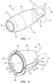
- FIG. 1 is a perspective illustration of an aircraft propulsion system 20 for an aircraft such as, but not limited to, a commercial airliner, a business jet, a cargo plane, etc.
- This propulsion system 20 includes a nacelle 22 and a gas turbine engine.
- the gas turbine engine may be configured as a turbojet gas turbine engine; however, the present disclosure is not limited to such an exemplary gas turbine engine configuration.
- the nacelle 22 is configured to house and provide an aerodynamic cover for the gas turbine engine.
- the nacelle 22 extends along an axial centerline 24 of the aircraft propulsion system 20 between a nacelle upstream, forward end 26 and a nacelle downstream, aft end 28.
- the nacelle 22 of FIG. 1 includes a nacelle inlet structure 30, one or more cowls 32 (one such cowl visible in FIG. 1 ) and a nacelle aft structure 34, which is configured as part of, or includes, a thrust reverser 36 such as, but not limited to, a target-type thrust reverser.
- target-type thrust reverser and clamshell-type thrust reverser herein may both describe a thrust reverser with one or more (e.g., a pair of) outwardly pivoting doors.
- the doors of a clamshell-type thrust reverser may redirect at least a portion of the hot gas stream and, in some embodiments, also a cold gas stream where the gas turbine engine is a turbofan gas turbine engine, for example.
- the inlet structure 30 is disposed at the nacelle forward end 26.
- the inlet structure 30 is configured to direct a stream of air through an inlet opening at the nacelle forward end 26 and into a forward-most stage (e.g., a low-pressure compressor (LPC) stage or a fan stage) of the gas turbine engine.
- a forward-most stage e.g., a low-pressure compressor (LPC) stage or a fan stage
- the cowls 32 are disposed axially between the inlet structure 30 and the aft structure 34.
- the cowls 32 are configured to provide an aerodynamic covering for a casing of the gas turbine engine.
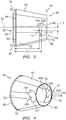
- the aft structure 34 includes a fixed structure 38, a first thrust reverser door 40 (e.g., shown as the "upper door"), a second thrust reverser door 42 (e.g., shown as the "lower” door), a first support arm 35, a second support arm 37, a pair of first thrust reverser door hinges 39A, 39B ("FTRD hinges"), and a pair of second thrust reverser door hinge 41A, 41B (“STRD hinges").
- the aft structure 34 and its components are configured to form an aft portion of an outer aerodynamic flow surface 46 of the nacelle 22 (see FIG. 1 ).
- the aft structure 34 and its components are also configured to form an aft portion of an inner aerodynamic flow surface 48.
- the aft portion of the inner aerodynamic flow surface 48 forms an outer peripheral boundary of an aft-most portion of a gas path 50 within the aircraft propulsion system 20; e.g., a core gas path.
- the aft-most portion of the gas path 50 may receive a mixed gas flow (e.g., a mix of a core gas and/or bypass air) from an upstream portion (or portions) of the gas turbine engine; e.g., from a bypass duct and/or core flow of the gas turbine engine.
- a mixed gas flow e.g., a mix of a core gas and/or bypass air
- the aft-most portion of the gas path 50 extends axially along the axial centerline 24 within the aircraft propulsion system 20 to an annular trailing edge 52 of a gas path nozzle 54, at which the gas path 50 meets an exterior environment surrounding the aircraft propulsion system 20.
- the fixed structure 38 has a generally tubular configuration, and extends axially along the centerline 24 between a fixed structure forward end 56 and a fixed structure aft end 58.
- a portion of the fixed structure 38 adjacent the forward end 56 is annular, extending completely around the circumference of the fixed structure 38.
- a portion of the fixed structure 38 adjacent the aft end 58 includes a pair of segments 44A, 44B, disposed on opposite sides of the fixed structure 38, each extending a limited circumferential distance, and thereby creating a first void 60 (e.g., an "upper” void) and a second void 62 (e.g., a "lower” void).
- each thrust reverser door 40, 42 includes an inner arcuate panel 70, 86 that is configured to mate with the fixed structure segments 44A, 44B to collectively create an annular structure; e.g., a continuation of the forward annular portion of the fixed structure 38.
- the interior surface 63 of the fixed structure 38 forms a respective portion of the inner aerodynamic flow surface 48.
- inner panels may be attached to the interior surface 63 of the fixed structure 38 to create the respective portion of the inner aerodynamic flow surface 48.
- the first support arm 35 extends axially between a forward end 96 and an aft end 98. At the aft end 98, the first support arm 35 includes an arcuately shaped flange surface 100.
- the second support arm 37 extends axially between a forward end 102 and an aft end 104. At the aft end 104, the second support arm 37 includes an arcuately shaped flange surface 106.
- the first and second support arms 35, 37 are configured the same, albeit as right and left versions. In other embodiments, the first and second support arms 35, 37 may be configured differently from one another.
- the first support arm 35 is disposed on a first side of the aft structure 34
- the second support arm 37 is disposed on a second side (opposite the first side) of the aft structure 34.
- the first and second support arms 35, 37 may be integrally formed with the fixed structure 38.
- the first and second support arms 35, 37 may be independent of, but attached to, the fixed structure 38.
- the first thrust reverser door 40 extends between a first (e.g., forward) door end 64 and a second (e.g., aft) door end 66.
- the aft structure 34 is configured to form an aft portion of an outer aerodynamic flow surface 46 of the nacelle 22 (see FIG. 1 ).
- the first thrust reverser door 40 extends circumferentially (e.g., between 150-180 degrees) about the centerline 24 between opposing door sides 68A, 68B.
- the first thrust reverser door 40 includes an inner arcuate panel 70 and an outer arcuate panel 72.
- the outer arcuate panel 72 includes an interior surface 108 and an exterior surface 110.
- the inner arcuate panel 70 is contiguous with the interior surface 108 of the outer arcuate panel 72 and may be attached to the interior surface 108. As indicated above, the inner arcuate panel 70 is configured to mate with the aft segments 44A, 44B of the fixed structure 38 to define a respective portion of the inner aerodynamic surface 48 and, thus, a respective outer peripheral boundary portion of the gas path 50 when the first thrust reverser door 40 is in its stowed position. Thus, when the first thrust reverser door 40 is in the stowed (e.g., closed) position, the interior surface 112 of the inner arcuate panel 70 is substantially flush with the interior surface 63 of the fixed structure 38.
- the exterior surface 110 of the outer arcuate panel 72 defines a respective portion of the outer aerodynamic surface 46 (see FIG. 1 ).
- the outer arcuate panel 72 is configured to circumferentially and axially overlap a portion of the fixed structure 38.
- the first thrust reverser door 40 is pivotally attached to both the first and second support arms 35, 37 via the FTRD hinges 39A, 39B.
- one of the FTRD hinges 39A, 39B is fixedly attached (i.e., non-rotationally attached) to one side of the first thrust reverser door 40 and pivotally attached via a pivot joint 74A, 74B to one of the first or second support arms 35, 37
- the other FTRD hinges 39A, 39B is fixedly attached (i.e., non-rotationally attached) to the opposite side of the first thrust reverser door 40 and pivotally attached via a pivot joint 74A, 74B to the other of the first or second support arms 35, 37.
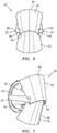
- a first actuator 76 (e.g., a hydraulic, pneumatic or mechanical linear actuator) is configured between and attached to the fixed structure 38 and the first thrust reverser door 40. With this configuration, the first actuator 76 is operable to move (e.g., pivot) the first thrust reverser door 40 between a stowed position (e.g., see FIGS. 2-4 ) and one or more deployed positions (e.g., FIG. 5 depicts the first thrust reverser door 40 in a completely deployed configuration). As will be explained below, when the first thrust reverser door 40 is in a deployed configuration, a first thrust reverser passage 78 is opened up between the fixed structure 38 and the door 40.
- a first thrust reverser passage 78 is opened up between the fixed structure 38 and the door 40.
- the second thrust reverser door 42 extends between a first (e.g., forward) door end 80 and a second (e.g., aft) door end 82.
- the aft structure 34 is configured to form an aft portion of an outer aerodynamic flow surface 46 of the nacelle 22 (see FIG. 1 ).
- the second thrust reverser door 42 extends circumferentially (e.g., between 150-180 degrees) about the centerline 24 between opposing door sides 84A, 84B.
- the second thrust reverser door 42 includes an inner arcuate panel 86 and an outer arcuate panel 88.
- the outer arcuate panel 88 includes an interior surface 114 and an exterior surface 116.
- the inner arcuate panel 86 is contiguous with the interior surface 114 of the outer arcuate panel 88 and may be attached to the interior surface 114. As indicated above, the inner arcuate panel 86 is configured to mate with the aft segments 44A, 44B of the fixed structure 38 to define a respective portion of the inner aerodynamic surface 48 and, thus, a respective outer peripheral boundary portion of the gas path 50 when the first thrust reverser door 40 is in its stowed position. Thus, when the second thrust reverser door 42 is in the stowed (e.g., closed) position, the interior surface 118 of the inner arcuate panel 86 is substantially flush with the interior surface 63 of the fixed structure 38.
- the exterior surface 116 of the outer arcuate panel 88 defines a respective portion of the outer aerodynamic surface 46 (see FIG. 1 ).
- the outer arcuate panel 88 is configured to circumferentially and axially overlap a portion of the fixed structure 38.
- the second thrust reverser door 42 is pivotally attached to both the first and second support arms 35, 37 via the STRD hinges 41A, 41B.
- one of the STRD hinges 41A, 41B is fixedly attached (i.e., non-rotationally attached) to one side of the second thrust reverser door 42 and pivotally attached via a pivot joint 90A, 90B to one of the first or second support arms 35, 37
- the other STRD hinges 41A, 41B is fixedly attached (i.e., non-rotationally attached) to the opposite side of the second thrust reverser door 42 and pivotally attached via a pivot joint 90A, 90B to the other of the first or second support arms 35, 37.
- a second actuator 92 e.g., a hydraulic, pneumatic or mechanical linear actuator
- the second actuator 92 is operable to move (e.g., pivot) the second thrust reverser door 42 between a stowed position (e.g., see FIGS. 2-4 ) and one or more deployed positions (e.g., FIG. 5 depicts the second thrust reverser door 42 in a completely deployed configuration).
- a second thrust reverser passage 94 is opened up between the fixed structure 38 and the door 42.
- pivot joints 74A, 74B for the first thrust reverser door 40 are disposed on opposite sides of the aft structure 34.
- the pivot joints 74A, 74B are disposed in the same position on the opposite sides; e.g., axial distance "Y1" from the forward end 56 of the fixed structure 38, and radial distance "X” from the axial centerline 24.
- the pivot joints 90A, 90B for the second thrust reverser door 42 are disposed on opposite sides of the aft structure 34.
- the pivot joints 90A, 90B are disposed in the same position on the opposite sides; e.g., axial distance "Y2" from the forward end 56 of the fixed structure 38, and radial distance "X” from the axial centerline 24.
- the first thrust reverser door 40 pivot joints 74A, 74B and the second thrust reverser door 42 pivot joints 90A, 90B are radially displaced the same distance "X” from the axial centerline 24.
- the axial distance "Y2" for the second thrust reverser door pivot joints 90A, 90B is greater than the axial distance "Y1" for the first thrust reverser door pivot joints 74A, 74B.
- the distance "X" is described from the axial centerline 24 of the nacelle 22.
- the present disclosure is not limited to locating the pivot joints off of the axial centerline 24. Rather, the reference datums of the nacelle centerline 24 and the forward end 56 of the fixed structure 38 are arbitrarily chosen for explanation sake. In some instances, the nacelle axial centerline 24 may be collinear with the engine centerline, but not necessarily. It should be noted further that the distances "Y1" and "Y2" are described above as referenced from the forward end 56 of the fixed structure 38.
- the forward end 56 of the fixed structure 38 is an arbitrarily chosen reference point, and the distances "Y1" and “Y2" may be referenced from an alternative reference point, subject to the statement that the axial distance "Y2" for the second thrust reverser door pivot joints 90A, 90B is greater than the axial distance "Y1" for the first thrust reverser door pivot joints 74A, 74B.
- thrust reverser permit the thrust reverser doors 40, 42 to be positioned in an aft position, and to rotate without interference. Positioning the thrust reverser doors 40, 42 in this manner facilitates the thrust reverser achieving "area match".
- area match refers to an aerodynamic match between the gas path area when the thrust reverser doors are disposed in the stowed position and when the thrust reverser doors are fully deployed.
- thrust reverser doors can be articulated from a stowed position to a fully deployed position without interfering with one another. This aspect of the present disclosure avoids the need for timed or synchronized deployment of the thrust reverser doors 40, 42.
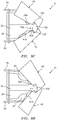
- FIGS. 9A-9E illustrate a sequence of the thrust reverser 36 deploying, where the thrust reverser doors 40 and 42 are stowed in FIG. 9A and the thrust reverser doors 40 and 42 are fully deployed in FIG. 9E .
- the first and the second actuators 76 and 92 respectively push against the thrust reverser doors 40 and 42 causing the doors 40 and 42 to pivot about the pivot joints 74A, 74B and 90A, 90B.
- the thrust reverser doors 40 and 42 pivot, a forward portion of each door 40, 42 projects radially outward into the surrounding environment and an aft portion of each door 40, 42 projects radially inward into the gas path 50.
- the aft portions of the doors 40, 42 are thereby operable to at least partially obstruct the gas path 50 proximate the nozzle 54, and redirect the gas flowing axially aft through the gas path 50 radially outward and forward through the thrust reverser passages 78 and 94.
- the first thrust reverser door 40 includes a pair of seal segments 120; i.e., one seal segment 120 engages the first support arm flange surface 100 and the other seal segment 120 engages the second support arm flange surface 106.
- the second thrust reverser door 42 includes a pair of seal segments 122; i.e., one seal segment 122 engages the first support arm flange surface 100 and the other seal segment 122 engages the second support arm flange surface 106.
- the present disclosure thrust reverser 36 is shown in the FIGURES as having a first thrust reverser door 40 disposed vertically, radially above a second thrust reverser door 42.
- the present disclosure is not limited to thrust reverser doors 40, 42 vertically, radially aligned.
- the present disclosure thrust reverser doors may actuate laterally.
- the FIGURES show the first thrust reverser door 40 and the second thrust reverser door 42 with particular pivot axes.
- the described pivot axes cause a portion of the first thrust reverser door 40 to be disposed axially aft of a portion of the second thrust reverser door 42.
- the described configurations of the doors 40, 42 and their respective pivot axes could be reversed.
Landscapes
- Engineering & Computer Science (AREA)
- Chemical & Material Sciences (AREA)
- Combustion & Propulsion (AREA)
- Mechanical Engineering (AREA)
- General Engineering & Computer Science (AREA)
- Structures Of Non-Positive Displacement Pumps (AREA)
Applications Claiming Priority (1)
| Application Number | Priority Date | Filing Date | Title |
|---|---|---|---|
| US16/055,791 US11187187B2 (en) | 2018-08-06 | 2018-08-06 | Thrust reverser |
Publications (2)
| Publication Number | Publication Date |
|---|---|
| EP3640466A1 true EP3640466A1 (de) | 2020-04-22 |
| EP3640466B1 EP3640466B1 (de) | 2022-07-20 |
Family
ID=67551153
Family Applications (1)
| Application Number | Title | Priority Date | Filing Date |
|---|---|---|---|
| EP19190250.1A Active EP3640466B1 (de) | 2018-08-06 | 2019-08-06 | Schubumkehrer |
Country Status (2)
| Country | Link |
|---|---|
| US (1) | US11187187B2 (de) |
| EP (1) | EP3640466B1 (de) |
Families Citing this family (3)
| Publication number | Priority date | Publication date | Assignee | Title |
|---|---|---|---|---|
| FR3105988B1 (fr) * | 2020-01-02 | 2021-12-03 | Safran Nacelles | Inverseur de poussée comprenant des portes formant en position ouverte une ouverture de déflexion d’air vers le haut |
| US12000358B1 (en) * | 2023-02-14 | 2024-06-04 | Pratt & Whitney Canada Corp. | Gas turbine engine nozzle loft for thrust reverser |
| US20250277475A1 (en) * | 2024-03-04 | 2025-09-04 | Textron Aviation Inc. | Aircraft Thrust Reverser Corrosion Shield |
Citations (2)
| Publication number | Priority date | Publication date | Assignee | Title |
|---|---|---|---|---|
| US5779192A (en) * | 1994-11-30 | 1998-07-14 | Societe Hispano-Suiza | Thrust reverser with improved forward thrust efficiency |
| EP3546735A1 (de) * | 2018-03-30 | 2019-10-02 | Rohr, Inc. | Hybrid-schubumkehrer für eine drehtür |
Family Cites Families (12)
| Publication number | Priority date | Publication date | Assignee | Title |
|---|---|---|---|---|
| GB1002709A (en) * | 1964-02-03 | 1965-08-25 | Rolls Royce | Improvements in or relating to thrust reversers for jet propulsion engines |
| FR2486153B1 (fr) | 1980-07-04 | 1985-10-04 | Hurel Dubois Avions | Inverseur de poussee pour moteur a reaction, destine notamment a equiper un aeronef |
| US5103634A (en) * | 1988-06-10 | 1992-04-14 | The Boeing Company | Thrust reversing system and method |
| US5176340A (en) | 1991-11-26 | 1993-01-05 | Lair Jean Pierre | Thrust reverser with a planar exit opening |
| FR2742482B1 (fr) | 1995-12-19 | 1998-02-06 | Hurel Dubois Avions | Inverseur de poussee a tuyere a section reglable pour moteur d'avion a reaction |
| CA2486172C (en) | 2002-05-21 | 2010-11-09 | The Nordam Group, Inc. | Variable area thrust reverser nozzle |
| US8015797B2 (en) * | 2006-09-21 | 2011-09-13 | Jean-Pierre Lair | Thrust reverser nozzle for a turbofan gas turbine engine |
| US8002217B2 (en) | 2007-11-16 | 2011-08-23 | Spirit Aerosystems, Inc. | System for adjustment of thrust reverser pivot door |
| US8127530B2 (en) * | 2008-06-19 | 2012-03-06 | The Nordam Group, Inc. | Thrust reverser for a turbofan gas turbine engine |
| FR3016863B1 (fr) * | 2014-01-29 | 2017-05-26 | Snecma | Nacelle pour turboreacteur d'avion |
| US11396854B2 (en) * | 2017-10-25 | 2022-07-26 | Rohr, Inc. | Hinge mechanism for pivot door thrust reversers |
| US10704495B2 (en) * | 2017-11-27 | 2020-07-07 | Rohr, Inc. | Pre-exit pivot door thrust reverser |
-
2018
- 2018-08-06 US US16/055,791 patent/US11187187B2/en active Active
-
2019
- 2019-08-06 EP EP19190250.1A patent/EP3640466B1/de active Active
Patent Citations (2)
| Publication number | Priority date | Publication date | Assignee | Title |
|---|---|---|---|---|
| US5779192A (en) * | 1994-11-30 | 1998-07-14 | Societe Hispano-Suiza | Thrust reverser with improved forward thrust efficiency |
| EP3546735A1 (de) * | 2018-03-30 | 2019-10-02 | Rohr, Inc. | Hybrid-schubumkehrer für eine drehtür |
Also Published As
| Publication number | Publication date |
|---|---|
| US11187187B2 (en) | 2021-11-30 |
| EP3640466B1 (de) | 2022-07-20 |
| US20200040844A1 (en) | 2020-02-06 |
Similar Documents
| Publication | Publication Date | Title |
|---|---|---|
| JP6167266B2 (ja) | 逆推力装置アセンブリおよび動作の方法 | |
| US9016040B2 (en) | Thrust reverser system with translating-rotating cascade and method of operation | |
| EP2570641B1 (de) | Lüftergehäuse mit Schubumkehrgitter, zugehöriger Fan und Gasturbinentriebwerk | |
| US10570853B2 (en) | Thrust reverser assembly | |
| US11149686B2 (en) | Thrust reverser assembly | |
| EP3591204B1 (de) | Schubumkehrer mit verschiebbarem hinterkantenkörper | |
| US20090301056A1 (en) | Aircraft engine thrust reverser | |
| EP2921686B1 (de) | Blockertürverriegelungsmechanismus einer Schubumkehrvorrichtung für ein Mantelstromtriebwerk | |
| US10184426B2 (en) | Thrust reverser with forward positioned blocker doors | |
| WO2005028303A2 (en) | Self stowing thrust reverser | |
| EP3640466B1 (de) | Schubumkehrer | |
| US20190032600A1 (en) | Thrust reverser assembly | |
| EP3441601B1 (de) | Schubumkehrstopp für turbinentriebwerk | |
| US20160245232A1 (en) | Blocker Door Configuration for a Thrust Reverser of a Turbofan Engine | |
| EP4198292B1 (de) | Düsenanordnung mit variablem querschnitt und betriebsverfahren | |
| US20230192308A1 (en) | Nacelle for an aircraft propulsion assembly comprising a flap for closing a recess for the passage of an actuator |
Legal Events
| Date | Code | Title | Description |
|---|---|---|---|
| PUAI | Public reference made under article 153(3) epc to a published international application that has entered the european phase |
Free format text: ORIGINAL CODE: 0009012 |
|
| STAA | Information on the status of an ep patent application or granted ep patent |
Free format text: STATUS: THE APPLICATION HAS BEEN PUBLISHED |
|
| AK | Designated contracting states |
Kind code of ref document: A1 Designated state(s): AL AT BE BG CH CY CZ DE DK EE ES FI FR GB GR HR HU IE IS IT LI LT LU LV MC MK MT NL NO PL PT RO RS SE SI SK SM TR |
|
| STAA | Information on the status of an ep patent application or granted ep patent |
Free format text: STATUS: REQUEST FOR EXAMINATION WAS MADE |
|
| 17P | Request for examination filed |
Effective date: 20201022 |
|
| RBV | Designated contracting states (corrected) |
Designated state(s): AL AT BE BG CH CY CZ DE DK EE ES FI FR GB GR HR HU IE IS IT LI LT LU LV MC MK MT NL NO PL PT RO RS SE SI SK SM TR |
|
| GRAP | Despatch of communication of intention to grant a patent |
Free format text: ORIGINAL CODE: EPIDOSNIGR1 |
|
| STAA | Information on the status of an ep patent application or granted ep patent |
Free format text: STATUS: GRANT OF PATENT IS INTENDED |
|
| INTG | Intention to grant announced |
Effective date: 20220211 |
|
| GRAS | Grant fee paid |
Free format text: ORIGINAL CODE: EPIDOSNIGR3 |
|
| GRAA | (expected) grant |
Free format text: ORIGINAL CODE: 0009210 |
|
| STAA | Information on the status of an ep patent application or granted ep patent |
Free format text: STATUS: THE PATENT HAS BEEN GRANTED |
|
| AK | Designated contracting states |
Kind code of ref document: B1 Designated state(s): AL AT BE BG CH CY CZ DE DK EE ES FI FR GB GR HR HU IE IS IT LI LT LU LV MC MK MT NL NO PL PT RO RS SE SI SK SM TR |
|
| REG | Reference to a national code |
Ref country code: CH Ref legal event code: EP |
|
| REG | Reference to a national code |
Ref country code: DE Ref legal event code: R096 Ref document number: 602019017122 Country of ref document: DE |
|
| REG | Reference to a national code |
Ref country code: AT Ref legal event code: REF Ref document number: 1505655 Country of ref document: AT Kind code of ref document: T Effective date: 20220815 |
|
| REG | Reference to a national code |
Ref country code: IE Ref legal event code: FG4D |
|
| REG | Reference to a national code |
Ref country code: LT Ref legal event code: MG9D |
|
| REG | Reference to a national code |
Ref country code: NL Ref legal event code: MP Effective date: 20220720 |
|
| PG25 | Lapsed in a contracting state [announced via postgrant information from national office to epo] |
Ref country code: SE Free format text: LAPSE BECAUSE OF FAILURE TO SUBMIT A TRANSLATION OF THE DESCRIPTION OR TO PAY THE FEE WITHIN THE PRESCRIBED TIME-LIMIT Effective date: 20220720 Ref country code: RS Free format text: LAPSE BECAUSE OF FAILURE TO SUBMIT A TRANSLATION OF THE DESCRIPTION OR TO PAY THE FEE WITHIN THE PRESCRIBED TIME-LIMIT Effective date: 20220720 Ref country code: PT Free format text: LAPSE BECAUSE OF FAILURE TO SUBMIT A TRANSLATION OF THE DESCRIPTION OR TO PAY THE FEE WITHIN THE PRESCRIBED TIME-LIMIT Effective date: 20221121 Ref country code: NO Free format text: LAPSE BECAUSE OF FAILURE TO SUBMIT A TRANSLATION OF THE DESCRIPTION OR TO PAY THE FEE WITHIN THE PRESCRIBED TIME-LIMIT Effective date: 20221020 Ref country code: NL Free format text: LAPSE BECAUSE OF FAILURE TO SUBMIT A TRANSLATION OF THE DESCRIPTION OR TO PAY THE FEE WITHIN THE PRESCRIBED TIME-LIMIT Effective date: 20220720 Ref country code: LV Free format text: LAPSE BECAUSE OF FAILURE TO SUBMIT A TRANSLATION OF THE DESCRIPTION OR TO PAY THE FEE WITHIN THE PRESCRIBED TIME-LIMIT Effective date: 20220720 Ref country code: LT Free format text: LAPSE BECAUSE OF FAILURE TO SUBMIT A TRANSLATION OF THE DESCRIPTION OR TO PAY THE FEE WITHIN THE PRESCRIBED TIME-LIMIT Effective date: 20220720 Ref country code: FI Free format text: LAPSE BECAUSE OF FAILURE TO SUBMIT A TRANSLATION OF THE DESCRIPTION OR TO PAY THE FEE WITHIN THE PRESCRIBED TIME-LIMIT Effective date: 20220720 Ref country code: ES Free format text: LAPSE BECAUSE OF FAILURE TO SUBMIT A TRANSLATION OF THE DESCRIPTION OR TO PAY THE FEE WITHIN THE PRESCRIBED TIME-LIMIT Effective date: 20220720 |
|
| REG | Reference to a national code |
Ref country code: AT Ref legal event code: MK05 Ref document number: 1505655 Country of ref document: AT Kind code of ref document: T Effective date: 20220720 |
|
| PG25 | Lapsed in a contracting state [announced via postgrant information from national office to epo] |
Ref country code: PL Free format text: LAPSE BECAUSE OF FAILURE TO SUBMIT A TRANSLATION OF THE DESCRIPTION OR TO PAY THE FEE WITHIN THE PRESCRIBED TIME-LIMIT Effective date: 20220720 Ref country code: IS Free format text: LAPSE BECAUSE OF FAILURE TO SUBMIT A TRANSLATION OF THE DESCRIPTION OR TO PAY THE FEE WITHIN THE PRESCRIBED TIME-LIMIT Effective date: 20221120 Ref country code: HR Free format text: LAPSE BECAUSE OF FAILURE TO SUBMIT A TRANSLATION OF THE DESCRIPTION OR TO PAY THE FEE WITHIN THE PRESCRIBED TIME-LIMIT Effective date: 20220720 Ref country code: GR Free format text: LAPSE BECAUSE OF FAILURE TO SUBMIT A TRANSLATION OF THE DESCRIPTION OR TO PAY THE FEE WITHIN THE PRESCRIBED TIME-LIMIT Effective date: 20221021 |
|
| REG | Reference to a national code |
Ref country code: CH Ref legal event code: PL |
|
| REG | Reference to a national code |
Ref country code: DE Ref legal event code: R097 Ref document number: 602019017122 Country of ref document: DE |
|
| PG25 | Lapsed in a contracting state [announced via postgrant information from national office to epo] |
Ref country code: SM Free format text: LAPSE BECAUSE OF FAILURE TO SUBMIT A TRANSLATION OF THE DESCRIPTION OR TO PAY THE FEE WITHIN THE PRESCRIBED TIME-LIMIT Effective date: 20220720 Ref country code: RO Free format text: LAPSE BECAUSE OF FAILURE TO SUBMIT A TRANSLATION OF THE DESCRIPTION OR TO PAY THE FEE WITHIN THE PRESCRIBED TIME-LIMIT Effective date: 20220720 Ref country code: MC Free format text: LAPSE BECAUSE OF FAILURE TO SUBMIT A TRANSLATION OF THE DESCRIPTION OR TO PAY THE FEE WITHIN THE PRESCRIBED TIME-LIMIT Effective date: 20220720 Ref country code: LU Free format text: LAPSE BECAUSE OF NON-PAYMENT OF DUE FEES Effective date: 20220806 Ref country code: LI Free format text: LAPSE BECAUSE OF NON-PAYMENT OF DUE FEES Effective date: 20220831 Ref country code: DK Free format text: LAPSE BECAUSE OF FAILURE TO SUBMIT A TRANSLATION OF THE DESCRIPTION OR TO PAY THE FEE WITHIN THE PRESCRIBED TIME-LIMIT Effective date: 20220720 Ref country code: CZ Free format text: LAPSE BECAUSE OF FAILURE TO SUBMIT A TRANSLATION OF THE DESCRIPTION OR TO PAY THE FEE WITHIN THE PRESCRIBED TIME-LIMIT Effective date: 20220720 Ref country code: CH Free format text: LAPSE BECAUSE OF NON-PAYMENT OF DUE FEES Effective date: 20220831 Ref country code: AT Free format text: LAPSE BECAUSE OF FAILURE TO SUBMIT A TRANSLATION OF THE DESCRIPTION OR TO PAY THE FEE WITHIN THE PRESCRIBED TIME-LIMIT Effective date: 20220720 |
|
| REG | Reference to a national code |
Ref country code: BE Ref legal event code: MM Effective date: 20220831 |
|
| PLBE | No opposition filed within time limit |
Free format text: ORIGINAL CODE: 0009261 |
|
| STAA | Information on the status of an ep patent application or granted ep patent |
Free format text: STATUS: NO OPPOSITION FILED WITHIN TIME LIMIT |
|
| PG25 | Lapsed in a contracting state [announced via postgrant information from national office to epo] |
Ref country code: SK Free format text: LAPSE BECAUSE OF FAILURE TO SUBMIT A TRANSLATION OF THE DESCRIPTION OR TO PAY THE FEE WITHIN THE PRESCRIBED TIME-LIMIT Effective date: 20220720 Ref country code: EE Free format text: LAPSE BECAUSE OF FAILURE TO SUBMIT A TRANSLATION OF THE DESCRIPTION OR TO PAY THE FEE WITHIN THE PRESCRIBED TIME-LIMIT Effective date: 20220720 |
|
| 26N | No opposition filed |
Effective date: 20230421 |
|
| PG25 | Lapsed in a contracting state [announced via postgrant information from national office to epo] |
Ref country code: AL Free format text: LAPSE BECAUSE OF FAILURE TO SUBMIT A TRANSLATION OF THE DESCRIPTION OR TO PAY THE FEE WITHIN THE PRESCRIBED TIME-LIMIT Effective date: 20220720 |
|
| PG25 | Lapsed in a contracting state [announced via postgrant information from national office to epo] |
Ref country code: IE Free format text: LAPSE BECAUSE OF NON-PAYMENT OF DUE FEES Effective date: 20220806 |
|
| PG25 | Lapsed in a contracting state [announced via postgrant information from national office to epo] |
Ref country code: SI Free format text: LAPSE BECAUSE OF FAILURE TO SUBMIT A TRANSLATION OF THE DESCRIPTION OR TO PAY THE FEE WITHIN THE PRESCRIBED TIME-LIMIT Effective date: 20220720 |
|
| PG25 | Lapsed in a contracting state [announced via postgrant information from national office to epo] |
Ref country code: BE Free format text: LAPSE BECAUSE OF NON-PAYMENT OF DUE FEES Effective date: 20220831 |
|
| PG25 | Lapsed in a contracting state [announced via postgrant information from national office to epo] |
Ref country code: HU Free format text: LAPSE BECAUSE OF FAILURE TO SUBMIT A TRANSLATION OF THE DESCRIPTION OR TO PAY THE FEE WITHIN THE PRESCRIBED TIME-LIMIT; INVALID AB INITIO Effective date: 20190806 |
|
| PG25 | Lapsed in a contracting state [announced via postgrant information from national office to epo] |
Ref country code: CY Free format text: LAPSE BECAUSE OF FAILURE TO SUBMIT A TRANSLATION OF THE DESCRIPTION OR TO PAY THE FEE WITHIN THE PRESCRIBED TIME-LIMIT Effective date: 20220720 |
|
| PG25 | Lapsed in a contracting state [announced via postgrant information from national office to epo] |
Ref country code: MK Free format text: LAPSE BECAUSE OF FAILURE TO SUBMIT A TRANSLATION OF THE DESCRIPTION OR TO PAY THE FEE WITHIN THE PRESCRIBED TIME-LIMIT Effective date: 20220720 Ref country code: IT Free format text: LAPSE BECAUSE OF FAILURE TO SUBMIT A TRANSLATION OF THE DESCRIPTION OR TO PAY THE FEE WITHIN THE PRESCRIBED TIME-LIMIT Effective date: 20220720 |
|
| PG25 | Lapsed in a contracting state [announced via postgrant information from national office to epo] |
Ref country code: BG Free format text: LAPSE BECAUSE OF FAILURE TO SUBMIT A TRANSLATION OF THE DESCRIPTION OR TO PAY THE FEE WITHIN THE PRESCRIBED TIME-LIMIT Effective date: 20220720 |
|
| PG25 | Lapsed in a contracting state [announced via postgrant information from national office to epo] |
Ref country code: MT Free format text: LAPSE BECAUSE OF FAILURE TO SUBMIT A TRANSLATION OF THE DESCRIPTION OR TO PAY THE FEE WITHIN THE PRESCRIBED TIME-LIMIT Effective date: 20220720 |
|
| PGFP | Annual fee paid to national office [announced via postgrant information from national office to epo] |
Ref country code: DE Payment date: 20250724 Year of fee payment: 7 |
|
| PGFP | Annual fee paid to national office [announced via postgrant information from national office to epo] |
Ref country code: GB Payment date: 20250724 Year of fee payment: 7 |
|
| PGFP | Annual fee paid to national office [announced via postgrant information from national office to epo] |
Ref country code: FR Payment date: 20250723 Year of fee payment: 7 |
|
| PG25 | Lapsed in a contracting state [announced via postgrant information from national office to epo] |
Ref country code: TR Free format text: LAPSE BECAUSE OF FAILURE TO SUBMIT A TRANSLATION OF THE DESCRIPTION OR TO PAY THE FEE WITHIN THE PRESCRIBED TIME-LIMIT Effective date: 20220720 |
|
| P01 | Opt-out of the competence of the unified patent court (upc) registered |
Free format text: CASE NUMBER: UPC_APP_0018038_3640466/2025 Effective date: 20251217 |