EP3640491B1 - Dispositif d'étrier de frein - Google Patents
Dispositif d'étrier de frein Download PDFInfo
- Publication number
- EP3640491B1 EP3640491B1 EP18200739.3A EP18200739A EP3640491B1 EP 3640491 B1 EP3640491 B1 EP 3640491B1 EP 18200739 A EP18200739 A EP 18200739A EP 3640491 B1 EP3640491 B1 EP 3640491B1
- Authority
- EP
- European Patent Office
- Prior art keywords
- seat
- brake disk
- lining
- brake
- central axis
- Prior art date
- Legal status (The legal status is an assumption and is not a legal conclusion. Google has not performed a legal analysis and makes no representation as to the accuracy of the status listed.)
- Active
Links
Images




Classifications
-
- F—MECHANICAL ENGINEERING; LIGHTING; HEATING; WEAPONS; BLASTING
- F16—ENGINEERING ELEMENTS AND UNITS; GENERAL MEASURES FOR PRODUCING AND MAINTAINING EFFECTIVE FUNCTIONING OF MACHINES OR INSTALLATIONS; THERMAL INSULATION IN GENERAL
- F16D—COUPLINGS FOR TRANSMITTING ROTATION; CLUTCHES; BRAKES
- F16D55/00—Brakes with substantially-radial braking surfaces pressed together in axial direction, e.g. disc brakes
- F16D55/02—Brakes with substantially-radial braking surfaces pressed together in axial direction, e.g. disc brakes with axially-movable discs or pads pressed against axially-located rotating members
- F16D55/22—Brakes with substantially-radial braking surfaces pressed together in axial direction, e.g. disc brakes with axially-movable discs or pads pressed against axially-located rotating members by clamping an axially-located rotating disc between movable braking members, e.g. movable brake discs or brake pads
- F16D55/224—Brakes with substantially-radial braking surfaces pressed together in axial direction, e.g. disc brakes with axially-movable discs or pads pressed against axially-located rotating members by clamping an axially-located rotating disc between movable braking members, e.g. movable brake discs or brake pads with a common actuating member for the braking members
- F16D55/225—Brakes with substantially-radial braking surfaces pressed together in axial direction, e.g. disc brakes with axially-movable discs or pads pressed against axially-located rotating members by clamping an axially-located rotating disc between movable braking members, e.g. movable brake discs or brake pads with a common actuating member for the braking members the braking members being brake pads
- F16D55/226—Brakes with substantially-radial braking surfaces pressed together in axial direction, e.g. disc brakes with axially-movable discs or pads pressed against axially-located rotating members by clamping an axially-located rotating disc between movable braking members, e.g. movable brake discs or brake pads with a common actuating member for the braking members the braking members being brake pads in which the common actuating member is moved axially, e.g. floating caliper disc brakes
- F16D55/2265—Brakes with substantially-radial braking surfaces pressed together in axial direction, e.g. disc brakes with axially-movable discs or pads pressed against axially-located rotating members by clamping an axially-located rotating disc between movable braking members, e.g. movable brake discs or brake pads with a common actuating member for the braking members the braking members being brake pads in which the common actuating member is moved axially, e.g. floating caliper disc brakes the axial movement being guided by one or more pins engaging bores in the brake support or the brake housing
- F16D55/227—Brakes with substantially-radial braking surfaces pressed together in axial direction, e.g. disc brakes with axially-movable discs or pads pressed against axially-located rotating members by clamping an axially-located rotating disc between movable braking members, e.g. movable brake discs or brake pads with a common actuating member for the braking members the braking members being brake pads in which the common actuating member is moved axially, e.g. floating caliper disc brakes the axial movement being guided by one or more pins engaging bores in the brake support or the brake housing by two or more pins
-
- F—MECHANICAL ENGINEERING; LIGHTING; HEATING; WEAPONS; BLASTING
- F16—ENGINEERING ELEMENTS AND UNITS; GENERAL MEASURES FOR PRODUCING AND MAINTAINING EFFECTIVE FUNCTIONING OF MACHINES OR INSTALLATIONS; THERMAL INSULATION IN GENERAL
- F16D—COUPLINGS FOR TRANSMITTING ROTATION; CLUTCHES; BRAKES
- F16D55/00—Brakes with substantially-radial braking surfaces pressed together in axial direction, e.g. disc brakes
- F16D55/02—Brakes with substantially-radial braking surfaces pressed together in axial direction, e.g. disc brakes with axially-movable discs or pads pressed against axially-located rotating members
- F16D55/22—Brakes with substantially-radial braking surfaces pressed together in axial direction, e.g. disc brakes with axially-movable discs or pads pressed against axially-located rotating members by clamping an axially-located rotating disc between movable braking members, e.g. movable brake discs or brake pads
- F16D55/224—Brakes with substantially-radial braking surfaces pressed together in axial direction, e.g. disc brakes with axially-movable discs or pads pressed against axially-located rotating members by clamping an axially-located rotating disc between movable braking members, e.g. movable brake discs or brake pads with a common actuating member for the braking members
- F16D55/225—Brakes with substantially-radial braking surfaces pressed together in axial direction, e.g. disc brakes with axially-movable discs or pads pressed against axially-located rotating members by clamping an axially-located rotating disc between movable braking members, e.g. movable brake discs or brake pads with a common actuating member for the braking members the braking members being brake pads
- F16D55/226—Brakes with substantially-radial braking surfaces pressed together in axial direction, e.g. disc brakes with axially-movable discs or pads pressed against axially-located rotating members by clamping an axially-located rotating disc between movable braking members, e.g. movable brake discs or brake pads with a common actuating member for the braking members the braking members being brake pads in which the common actuating member is moved axially, e.g. floating caliper disc brakes
- F16D55/2265—Brakes with substantially-radial braking surfaces pressed together in axial direction, e.g. disc brakes with axially-movable discs or pads pressed against axially-located rotating members by clamping an axially-located rotating disc between movable braking members, e.g. movable brake discs or brake pads with a common actuating member for the braking members the braking members being brake pads in which the common actuating member is moved axially, e.g. floating caliper disc brakes the axial movement being guided by one or more pins engaging bores in the brake support or the brake housing
- F16D55/22655—Constructional details of guide pins
Definitions
- the disclosure relates to a brake caliper device, and more particularly to a brake caliper device for a vehicle.
- US patent application 5 622 241 A aims to disclose a trailer brake system providing a disc brake assembly with a caliper unit including a housing for mounting the pads for relative movement toward and away from the rotor and a cradle with spaced guide pins/tracks for securely supporting the housing at multiple, spaced points.
- the cradle includes a yoke having spaced arms and a cross piece for embracing the housing, and is independently mounted on a single pivot pin.
- First and second stops are provided on the bracket for engagement with the cross piece to limit the pivot movement of the caliper unit during vehicle backing and forward movement, respectively.
- Guide apertures are provided adjacent the distal end of the respective arms of the yoke and include an elastomeric bushing around the guide pins for cushioned in and out movement.
- the spaced guide tracks on the housing assist in providing axial stability.
- An elastomeric spring formed integrally with the bushing bodily centers the housing in the axial direction during the non-braking modes and provides added cushion effect.
- An elastomeric bumper at the first stop urges the caliper unit towards the second stop to prevent pressure release during vehicle forward movement, including in the braking mode.
- a relief valve feeds/exhausts a common transfer line to the cylinder in the housing of the caliper unit.
- Taiwanese Patent Publication Number 163856 discloses a conventional brake caliper device adapted to be mounted to a vehicle body and adapted to be used with a brake disk.
- the conventional brake caliper device includes a positioning frame that is adapted to be fixed to the vehicle body and that has opposite side parts for flanking the brake disk, a brake caliper that has opposite portions for flanking the positioning frame and the brake disk, and first and second brake pads that are respectively disposed at opposite sides of the brake disk.
- the positioning frame includes two guiding members .
- the brake caliper includes a first seat that is slidable relative to the positioning frame along an axis parallel to a central axis of the brake disc, and a second seat that is connected to the first seat.
- the first seat is formed with two receiving holes that respectively receive the guiding members, and a pressure member for pushing the first brake pad to abut against the brake disk.
- the second seat is proximate to the second brake pad.
- the positioning frame is easily driven by its own weight and the weights of the first and second brake pads to become inclined, such that the braking process become less smooth or even nonfunctional, which can be proven fatal.
- an object of the disclosure is to provide a brake caliper device that can alleviate the drawback of the prior art.
- the brake caliper device is adapted to be mounted to a vehicle body and adapted to be used with a brake disk.
- the brake disk has a first side surface and a second side surface opposite to the first side surface, both of which are perpendicular to a central axis of the brake disk.
- the brake caliper device has a positioning unit, a main body unit, a lining unit, and an actuating unit.
- the positioning unit includes a positioning member that is adapted to be fixed to the vehicle body, two upper guiding members that are connected to the positioning member and that extend along an axial direction parallel to the central axis, and a lower guiding member that is connected to the positioning member, that extends along the axial direction, and that is lower than the upper guiding members.
- the main body unit includes a first seat and a second seat.
- the first seat is connected to the upper guiding members and the lower guiding member, faces and is adapted to be adjacent to the first side surface of the brake disk, and is adapted to be movable along the axial direction relative to the first side surface of the brake disk.
- the second seat that is co-movably connected to the first seat, faces and is adapted to be adjacent to the second side surface of the brake disk faces and is adjacent to the second seat, and cooperates with the first seat to define a receiving space therebetween for receiving a part of the brake disk.
- the lining unit includes a first lining member that is adapted to be disposed between the first seat and the first side surface of the brake disk, that is disposed in the receiving space, and that is movable along the axial direction, and a second lining member that is adapted to be movably disposed between the second seat and the second side surface of the brake disk, that is disposed in the receiving space, and that is movable along the axial direction.
- the actuating unit is mounted to the first seat, is operable to push the first lining member to abut against the first side surface of the brake disk, so as to generate a counterforce to push the first seat away from the brake disk and to move the second seat to press the second lining member against the second side surface of the brake disk, thereby clamping the brake disk between the first and second lining members.
- the first seat of said main body unit has a first inner surface that is adjacent to said receiving space, a first outer surface that is opposite to said first inner surface, two upper through holes that extend through said first inner and outer surfaces and that respectively receive said upper guiding members, and a lower through hole that is located between said upper through holes and that receives said lower guiding member; and said lower guiding member is lower than said upper guiding members.
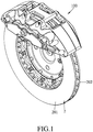
- an embodiment of a brake caliper device 100 is adapted to be mounted to a vehicle body 1 (see FIG. 4 ) and adapted to be used with a brake disk 2.
- the brake disk 2 has a first side surface 201 and a second side surface 202 opposite to the first side surface 201.
- the first and second side surfaces 201, 202 are perpendicular to a central axis (L) of the brake disk 2.
- the brake caliper device 100 includes a positioning unit 10, a main body unit 20, a lining unit 30, and an actuating unit 40.
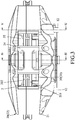
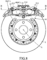
- the positioning unit 10 includes a positioning member 11 that is adapted to be fixed to the vehicle body 1, two upper guiding members 12 that are connected to the positioning member 11 and that are parallel to the central axis (L), a lower guiding member 13 that is connected to the positioning member 11, that is parallel to the central axis (L), and that is lower than the upper guiding members 12, and two first resilient sheets 14 that are connected to the positioning member 11.
- the positioning member 11 has a U-shaped cross-section perpendicular to the central axis (L) .
- the positioning member 11 has a base portion 111, and two side portions 112 that respectively and upwardly extend from opposite ends of the base portion 111.
- the base portion 111 has a top surface 115, and each of the side portions 112 has an inner surface 116 and a stepped shoulder surface 117 that is disposed between the top surface 115 of the base portion 111 and the side surface 116.
- the top surface 115, the side surfaces 116 and the shoulder surfaces 117 cooperatively define a first receiving groove 15.
- a top end of each of the side portions 112 distal from the base portion 111 is formed with an upper lock hole 113, and the base portion 111 is formed with a lower lock hole 114 that is disposed between the side portions 112.
- Each of the upper guiding members 12 is rod-shaped and engages fixedly the upper lock hole 113 of a respective one of the side portions 112.
- each of the first resilient sheets 14 is fixedly mounted to a respective one of the side portions 112 via a screw (as shown in FIG. 2 ) , and has an inverted V-shaped resilient portion 141.
- the main body unit 20 includes a first seat 21, a second seat 22, two second resilient sheets 23 that are connected to the second seat 22, and a connecting member 24.
- the first seat 21 faces and is adapted to be adjacent to the first side surface 201 of the brake disk 2.
- the second seat 22 faces and is adapted to be adjacent to the second side surface 202 of the brake disk 2.
- the first and second seats 21, 22 cooperatively define a receiving space 25 therebetween for receiving an upper part of the brake disk 2.
- the positioning member 11 of the positioning unit 10 is also received in the receiving space 25, and is adapted to be disposed between the first seat 21 and the first side surface 21 of the brake disk 2.
- the first seat 21 is connected to the upper guiding members 12 and the lower guiding member 13, and is movable parallel to the central axis (L) relative to the first side surface 201 of the brake disk 2.
- the first seat 21 has a first inner surface 211 that is adjacent to the receiving space 25, a first outer surface 212 that is opposite to the first inner surface 211, two upper through holes 213 that extend through the first inner and outer surfaces 211, 212 and that respectively receive the upper guiding members 12, a lower through hole 214 that is located between the upper through holes 213 and that receives the lower guiding member 13, and a plurality of piston chambers 215 (three in this embodiment) that are formed in the first inner surface 211.
- the second seat 22 has a base wall surface 223, two side wall surfaces 224 that respectively extend from opposite sides of the base wall surface 223 toward the receiving space 25, and two second inner surfaces 221 that respectively extend from the two side wall surfaces 224 away from each other and that are substantially parallel to the base wall surface 223.
- the base wall surface 223 and the second inner surfaces 221 are respectively distal from and proximate to the receiving space 25.
- the second seat 22 further has two support surfaces 225, each of which is perpendicularly connected to the side wall surface 223 and a respective one of the side wall surfaces 224.
- the base wall surfaces 223, the side wall surfaces 224 and the support surfaces 225 cooperatively define a second receiving groove 222 that is adjacent to the receiving space 25.
- each of the second resilient sheets 23 is fixedly mounted to a respective one of the side wall surfaces 224 via a screw (not shown) , and has an inverted V-shaped resilient portion 231.
- the connecting member 24 interconnects the first and second seats 21, 22, such that the second seat 22 is co-movable with the first seat 21.
- the lining unit 30 includes a first lining member 31 that is adapted to be disposed between the first seat 21 and the first side surface 201 of the brake disk 2, that is disposed in the receiving space 25 and that is movable parallel to the central axis (L) , and a second lining member 32 that is adapted to be movably disposed between the second seat 22 and the second side surface 202 of the brake disk 2, that is disposed in the receiving space 25 and that is movable parallel to the central axis (L) .
- the first lining member 31 is movably disposed in the first receiving groove 15 of the positioning unit 10, has two first abutting surfaces 311 that movably and respectively abut against the shoulder surfaces 117 of the side portions 112 of the positioning member 11, and a first top surface 312 that is opposite to the first abutting surfaces 311.
- the resilient portions 141 of the first resilient sheets 14 resiliently press against the first top surface 312 toward the base portion 111 of the positioning member 11.
- the second lining member 32 is received in the second receiving groove 222 of the second seat 22 of the main body unit 20, has two second abutting surfaces 321 that movably and respectively abut against the support surfaces 225 of the second seat 22 of the main body unit 20, and a second top surface 322 that is opposite to the second abutting surfaces 321.
- the resilient portion 231 of each of the second resilient sheets 23 resiliently presses against the second top surface 322, such that the second lining member 32 comes into contact with the support surfaces 225 of the second seat 22 of the main body unit 20.
- the actuating unit 40 is mounted to the first seat 21 of the main body unit 20, and includes a plurality of hydraulic pistons 41 that are respectively received in the piston chambers 215 of the first seat 21, and each of which has an end that abuts against the first lining member 31.
- pressurized oil is injected into the piston chambers 215, such that the hydraulic pistons 41 are hydraulically operated to push the first lining member 31 in a first direction (I) and toward the first side surface 201 of the brake disk 2.
- a counterforce begins to generate, pushing the first seat 21 of the main body unit 20 away from the brake disk 2 in a second direction (II) opposite to the first direction (I), and simultaneously moving the second seat 22 of the main body unit 20 in the second direction (II) to press the second lining member 32 against the second side surface 202 of the brake disk 2 (since the second seat 22 is co-movably connected to the first seat 31), thereby clamping the brake disk 2 between the first and second lining members 31, 32.
- the first seat 21 may stably move along the upper guiding members 12 and the lower guiding member 13 without becoming inclined, thereby ensuring that the movement of the main body unit 20 relative to the positioning unit 10 remain be stable for the braking process.
- the implementation of the lower guiding member 13, in conjunction with the upper guiding members 12, ensures that the positioning unit 10 is dimensionally stable and no longer prone to inclination, thereby ensuring smooth movement of the main body unit 20 during the braking process.
Landscapes
- Engineering & Computer Science (AREA)
- General Engineering & Computer Science (AREA)
- Mechanical Engineering (AREA)
- Braking Arrangements (AREA)
Claims (8)
- Dispositif d'étrier de frein (100) apte à être monté sur un corps de véhicule (1) et apte à être utilisé avec un disque de frein (2), le disque de frein (2) présentant une première surface latérale (201) et une deuxième surface latérale (202) opposée à la première surface latérale (201), la première et la deuxième surface latérale (201, 202) étant perpendiculaires à un axe central (L) du disque de frein (2), ledit dispositif d'étrier de frein (100) incluant :une unité de positionnement (10) incluant un élément de positionnement (11) qui est apte à être fixé au corps de véhicule (1), deux éléments de guidage supérieurs (12) qui sont connectés audit élément de positionnement (11) et qui sont parallèles à l'axe central (L), et un élément de guidage inférieur (13) qui est connecté audit élément de positionnement (11) et qui est parallèle à l'axe central (L) ;une unité de corps principal (20) incluant :un premier siège (21) qui est connecté auxdits éléments de guidage supérieurs (12) et audit élément de guidage inférieur (13), qui fait face et est apte à être adjacent à la première surface latérale (201) du disque de frein (2), et qui est apte à être mobile de manière parallèle à l'axe central (L) par rapport à la première surface latérale (201) du disque de frein (2), etun deuxième siège (22) qui est connecté de manière co-mobile audit premier siège (21), qui fait face et est apte à être adjacent à la deuxième surface latérale (202) du disque de frein (2), et qui interagit avec ledit premier siège (21) pour définir un espace de réception (25) entre eux pour recevoir une partie du disque de frein (2) ;une unité de garnissage (30) incluant un premier élément de garnissage (31) qui est apte à être disposé entre ledit premier siège (21) et la première surface latérale (201) du disque de frein (2), qui est disposé dans ledit espace de réception (25) et qui est mobile de manière parallèle à l'axe central (L), et un deuxième élément de garnissage (32) qui est apte à être disposé de manière mobile entre ledit deuxième siège (22) et la deuxième surface latérale (202) du disque de frein (2), qui est disposé dans ledit espace de réception (25) et qui est mobile de manière parallèle à l'axe central (L) ; etune unité d'actionnement (40) montée sur ledit premier siège (21), ladite unité d'actionnement (40) étant manœuvrable pour pousser ledit premier élément de garnissage (31) pour venir en butée contre la première surface latérale (201) du disque de frein (2), de manière à générer une force contraire pour pousser ledit premier siège (21) en éloignement du disque de frein (2) et pour déplacer ledit deuxième siège (22) pour appuyer ledit deuxième élément de garnissage (32) contre la deuxième surface latérale (202) du disque de frein (2), serrant ainsi le disque de frein (2) entre le premier et le deuxième élément de garnissage (31, 32) ;caractérisé en ce que :ledit premier siège (21) de ladite unité de corps principal (20) présente une première surface intérieure (211) qui est adjacente audit espace de réception (25), une première surface extérieure (212) qui est opposée à ladite première surface intérieure (211), deux trous traversants supérieurs (213) qui s'étendent à travers lesdites premières surfaces intérieure et extérieure (211, 212) et qui reçoivent respectivement lesdits éléments de guidage supérieurs (12), et un trou traversant inférieur (214) qui est situé entre lesdits trous traversants supérieurs (213) et qui reçoit ledit élément de guidage inférieur (13) ; etledit élément de guidage inférieur (13) est plus bas que lesdits éléments de guidage supérieurs (12).
- Le dispositif d'étrier de frein (100) tel que revendiqué dans la revendication 1, caractérisé en outre en ce que :ledit élément de positionnement (11) de ladite unité de positionnement (10) est reçue dans ledit espace de réception (25) et est apte à être disposé entre ledit premier siège (21) et la première surface latérale (201) du disque de frein (2) ; etledit élément de positionnement (11) présente une section transversale en forme de U perpendiculaire à l'axe central (L), et présente une partie de base (111) et deux parties latérales (112) qui s'étendent respectivement et vers le haut depuis des extrémités opposées de ladite partie de base (111) et qui interagissent avec ladite partie de base (111) pour définir une première rainure de réception (15) qui reçoit ledit premier élément de garnissage (31).
- Le dispositif d'étrier de frein (100) tel que revendiqué dans la revendication 2, caractérisé en outre en ce que :chacun desdits éléments de guidage supérieurs (12) est en forme de tige et est connecté à une extrémité supérieure d'une respective desdites parties latérales (112) dudit élément de positionnement (11) ; etledit élément de guidage inférieur (13) est en forme de tige, est connecté à ladite partie de base (111), et est situé sous et entre lesdits éléments de guidage supérieurs (12) ;une distance entre ledit élément de guidage inférieur (13) et l'axe central (L) est plus petite qu'une distance entre chacun desdits éléments de guidage supérieurs (12) et l'axe central (L).
- Le dispositif d'étrier de frein (100) tel que revendiqué dans la revendication 2, caractérisé en outre en ce que :ladite partie de base (111) dudit élément de positionnement (11) présente une surface supérieure (115) ;chacune desdites parties latérales (112) dudit élément de positionnement (11) présente une surface latérale intérieure (116) et une surface d'épaulement (117) qui est disposée entre ladite surface supérieure (115) de ladite partie de base (111) et ladite surface latérale (116) ;ladite surface supérieure (115) de ladite partie de base (111), et lesdites surfaces latérales (116) et lesdites surfaces d'épaulement (117) desdites parties latérales (112) définissent par interaction ladite première rainure de réception (15) ; etledit premier élément de garnissage (31) présente deux premières surfaces de butée (311) qui viennent en butée de manière mobile et respectivement contre lesdites surfaces d'épaulement (117) desdites parties latérales (112) dudit élément de positionnement (11).
- Le dispositif d'étrier de frein (100) tel que revendiqué dans la revendication 4, caractérisé en outre en ce que :ledit premier élément de garnissage (31) présente en outre une première surface supérieure (312) qui est opposée auxdites premières surfaces de butée (311) ; etladite unité de positionnement (10) inclut en outre deux premières feuilles souples (14) qui sont connectées audit élément de positionnement (11), et qui appuient de manière souple contre ladite première surface supérieure (312) dudit premier élément de garnissage (31) vers ladite partie de base (111) dudit élément de positionnement (11).
- Le dispositif d'étrier de frein (100) tel que revendiqué dans la revendication 1, caractérisé en outre en ce que :ledit premier siège (21) de ladite unité de corps principal (20) présente une première surface intérieure (211) qui est adjacente audit espace de réception (25), et une pluralité de chambres à piston (215) qui sont formées dans ladite première surface intérieure (211) ; etladite unité d'actionnement (40) inclut une pluralité de pistons hydrauliques (41) qui sont reçus respectivement dans lesdites chambres à piston (215), et qui sont manœuvrables hydrauliquement pour pousser ledit premier élément de garnissage (31) vers la première surface latérale (201) du disque de frein (2).
- Le dispositif d'étrier de frein (100) tel que revendiqué dans la revendication 1, caractérisé en outre en ce que :ledit deuxième siège (22) de ladite unité de corps principal (20) présente une surface de paroi de base (223),deux surfaces de paroi latérales (224) qui s'étendent respectivement depuis des côtés opposés de ladite surface de paroi de base (223) vers ledit espace de réception (25),deux deuxièmes surfaces intérieures (221) qui s'étendent respectivement depuis lesdites deux surfaces de paroi latérales (224) en éloignement l'une de l'autre et qui sont sensiblement parallèles à ladite surface de paroi de base (223), ladite surface de paroi de base (223) et lesdites deuxièmes surfaces intérieures (221) étant respectivement distales par rapport à et proches dudit espace de réception (25), etdeux surfaces de support (225), dont chacune est connectée perpendiculairement à ladite surface de paroi de base (223) et à une respective desdites surfaces de paroi latérales (224) ;ladite surface de paroi de base (223), lesdites surfaces de paroi latérales (224) et lesdites surfaces de support (225) définissent par interaction une deuxième rainure de réception (222) qui est adjacente audit espace de réception (25) et qui reçoit ledit deuxième élément de garnissage (32) ; etledit deuxième élément de garnissage (32) présente deux deuxièmes surfaces de butée (321) qui viennent en butée de manière mobile et respective contre lesdites surfaces de support (225) dudit deuxième siège (22) de ladite unité de corps principal (20).
- Le dispositif d'étrier de frein (100) tel que revendiqué dans la revendication 7, caractérisé en outre en ce que :ledit deuxième élément de garnissage (32) présente en outre une deuxième surface supérieure (322) qui est opposée auxdites deuxièmes surfaces de butée (321) ; etladite unité de corps principal (20) inclut en outre deux deuxièmes feuilles souples (23) qui sont connectées audit deuxième siège (22), et qui appuient de manière souple contre ladite deuxième surface supérieure (322) dudit deuxième élément de garnissage (32) de telle sorte que ledit deuxième élément de garnissage (32) entre en contact avec lesdites surfaces de support (225) dudit deuxième siège (22).
Priority Applications (1)
| Application Number | Priority Date | Filing Date | Title |
|---|---|---|---|
| EP18200739.3A EP3640491B1 (fr) | 2018-10-16 | 2018-10-16 | Dispositif d'étrier de frein |
Applications Claiming Priority (1)
| Application Number | Priority Date | Filing Date | Title |
|---|---|---|---|
| EP18200739.3A EP3640491B1 (fr) | 2018-10-16 | 2018-10-16 | Dispositif d'étrier de frein |
Publications (2)
| Publication Number | Publication Date |
|---|---|
| EP3640491A1 EP3640491A1 (fr) | 2020-04-22 |
| EP3640491B1 true EP3640491B1 (fr) | 2021-08-04 |
Family
ID=63878417
Family Applications (1)
| Application Number | Title | Priority Date | Filing Date |
|---|---|---|---|
| EP18200739.3A Active EP3640491B1 (fr) | 2018-10-16 | 2018-10-16 | Dispositif d'étrier de frein |
Country Status (1)
| Country | Link |
|---|---|
| EP (1) | EP3640491B1 (fr) |
Family Cites Families (4)
| Publication number | Priority date | Publication date | Assignee | Title |
|---|---|---|---|---|
| GB2018372B (en) * | 1978-04-07 | 1982-02-24 | Girling Ltd | Disc brakes for vehicles |
| US5622241A (en) * | 1995-09-12 | 1997-04-22 | Null; Robert L. | Trailer brake system with multiple point caliper unit mounting |
| DE10314437A1 (de) * | 2003-03-31 | 2004-10-14 | Continental Teves Ag & Co. Ohg | Bremsträger für eine Teilbelagscheibenbremse |
| TWI616603B (zh) * | 2016-05-20 | 2018-03-01 | Tw Racing Parts Inc | 電子式駐車卡鉗 |
-
2018
- 2018-10-16 EP EP18200739.3A patent/EP3640491B1/fr active Active
Non-Patent Citations (1)
| Title |
|---|
| None * |
Also Published As
| Publication number | Publication date |
|---|---|
| EP3640491A1 (fr) | 2020-04-22 |
Similar Documents
| Publication | Publication Date | Title |
|---|---|---|
| US10760630B2 (en) | Brake caliper device | |
| JP5156325B2 (ja) | 車両用キャリパブレーキ装置 | |
| AU2016280662B2 (en) | Disk brake for a utility vehicle and brake pad set | |
| WO2011024980A1 (fr) | Dispositif de frein à mâchoires | |
| EP2694350B1 (fr) | Récepteur de freinage de véhicule ferroviaire à porte-sabot | |
| EP3640491B1 (fr) | Dispositif d'étrier de frein | |
| JPS6238033Y2 (fr) | ||
| JP2009275782A (ja) | ピンスライド型車両用ディスクブレーキ | |
| KR20140067203A (ko) | 디스크 브레이크 | |
| KR20180060337A (ko) | 디스크 브레이크 | |
| CN212536487U (zh) | 一种制动钳总成 | |
| JP2008286234A (ja) | 鉄道車両用キャリパブレーキ装置 | |
| KR20230138982A (ko) | 패드 스프링 및 이를 구비하는 캘리퍼 브레이크 | |
| JP2011047427A (ja) | キャリパブレーキ装置 | |
| CN108825681B (zh) | 反动式卡钳装置 | |
| US20080156595A1 (en) | Disc brake apparatus of opposed-piston type | |
| JP2009162243A (ja) | 車両用キャリパブレーキ装置 | |
| JP6744737B2 (ja) | ブレーキ装置 | |
| EP1409885A1 (fr) | Compensateur d'usure de freins | |
| KR101394074B1 (ko) | 디스크 브레이크 | |
| JPS6334326B2 (fr) | ||
| KR100771009B1 (ko) | 차량용 디스크 브레이크 | |
| GB1563817A (en) | Disc brakes | |
| KR100784810B1 (ko) | 차량용 디스크 브레이크 | |
| CA2989723C (fr) | Frein a disque pour vehicule utilitaire et jeu de garnitures de frein |
Legal Events
| Date | Code | Title | Description |
|---|---|---|---|
| PUAI | Public reference made under article 153(3) epc to a published international application that has entered the european phase |
Free format text: ORIGINAL CODE: 0009012 |
|
| STAA | Information on the status of an ep patent application or granted ep patent |
Free format text: STATUS: THE APPLICATION HAS BEEN PUBLISHED |
|
| AK | Designated contracting states |
Kind code of ref document: A1 Designated state(s): AL AT BE BG CH CY CZ DE DK EE ES FI FR GB GR HR HU IE IS IT LI LT LU LV MC MK MT NL NO PL PT RO RS SE SI SK SM TR |
|
| AX | Request for extension of the european patent |
Extension state: BA ME |
|
| STAA | Information on the status of an ep patent application or granted ep patent |
Free format text: STATUS: REQUEST FOR EXAMINATION WAS MADE |
|
| 17P | Request for examination filed |
Effective date: 20200625 |
|
| RBV | Designated contracting states (corrected) |
Designated state(s): AL AT BE BG CH CY CZ DE DK EE ES FI FR GB GR HR HU IE IS IT LI LT LU LV MC MK MT NL NO PL PT RO RS SE SI SK SM TR |
|
| STAA | Information on the status of an ep patent application or granted ep patent |
Free format text: STATUS: EXAMINATION IS IN PROGRESS |
|
| 17Q | First examination report despatched |
Effective date: 20200904 |
|
| GRAP | Despatch of communication of intention to grant a patent |
Free format text: ORIGINAL CODE: EPIDOSNIGR1 |
|
| STAA | Information on the status of an ep patent application or granted ep patent |
Free format text: STATUS: GRANT OF PATENT IS INTENDED |
|
| INTG | Intention to grant announced |
Effective date: 20210215 |
|
| GRAS | Grant fee paid |
Free format text: ORIGINAL CODE: EPIDOSNIGR3 |
|
| GRAA | (expected) grant |
Free format text: ORIGINAL CODE: 0009210 |
|
| STAA | Information on the status of an ep patent application or granted ep patent |
Free format text: STATUS: THE PATENT HAS BEEN GRANTED |
|
| AK | Designated contracting states |
Kind code of ref document: B1 Designated state(s): AL AT BE BG CH CY CZ DE DK EE ES FI FR GB GR HR HU IE IS IT LI LT LU LV MC MK MT NL NO PL PT RO RS SE SI SK SM TR |
|
| REG | Reference to a national code |
Ref country code: GB Ref legal event code: FG4D |
|
| REG | Reference to a national code |
Ref country code: AT Ref legal event code: REF Ref document number: 1417273 Country of ref document: AT Kind code of ref document: T Effective date: 20210815 |
|
| REG | Reference to a national code |
Ref country code: CH Ref legal event code: EP |
|
| REG | Reference to a national code |
Ref country code: DE Ref legal event code: R096 Ref document number: 602018021122 Country of ref document: DE |
|
| REG | Reference to a national code |
Ref country code: IE Ref legal event code: FG4D |
|
| REG | Reference to a national code |
Ref country code: FI Ref legal event code: FGE |
|
| REG | Reference to a national code |
Ref country code: SE Ref legal event code: TRGR |
|
| REG | Reference to a national code |
Ref country code: NL Ref legal event code: FP |
|
| REG | Reference to a national code |
Ref country code: LT Ref legal event code: MG9D |
|
| REG | Reference to a national code |
Ref country code: AT Ref legal event code: MK05 Ref document number: 1417273 Country of ref document: AT Kind code of ref document: T Effective date: 20210804 |
|
| PG25 | Lapsed in a contracting state [announced via postgrant information from national office to epo] |
Ref country code: PT Free format text: LAPSE BECAUSE OF FAILURE TO SUBMIT A TRANSLATION OF THE DESCRIPTION OR TO PAY THE FEE WITHIN THE PRESCRIBED TIME-LIMIT Effective date: 20211206 Ref country code: NO Free format text: LAPSE BECAUSE OF FAILURE TO SUBMIT A TRANSLATION OF THE DESCRIPTION OR TO PAY THE FEE WITHIN THE PRESCRIBED TIME-LIMIT Effective date: 20211104 Ref country code: AT Free format text: LAPSE BECAUSE OF FAILURE TO SUBMIT A TRANSLATION OF THE DESCRIPTION OR TO PAY THE FEE WITHIN THE PRESCRIBED TIME-LIMIT Effective date: 20210804 Ref country code: BG Free format text: LAPSE BECAUSE OF FAILURE TO SUBMIT A TRANSLATION OF THE DESCRIPTION OR TO PAY THE FEE WITHIN THE PRESCRIBED TIME-LIMIT Effective date: 20211104 Ref country code: LT Free format text: LAPSE BECAUSE OF FAILURE TO SUBMIT A TRANSLATION OF THE DESCRIPTION OR TO PAY THE FEE WITHIN THE PRESCRIBED TIME-LIMIT Effective date: 20210804 Ref country code: RS Free format text: LAPSE BECAUSE OF FAILURE TO SUBMIT A TRANSLATION OF THE DESCRIPTION OR TO PAY THE FEE WITHIN THE PRESCRIBED TIME-LIMIT Effective date: 20210804 Ref country code: HR Free format text: LAPSE BECAUSE OF FAILURE TO SUBMIT A TRANSLATION OF THE DESCRIPTION OR TO PAY THE FEE WITHIN THE PRESCRIBED TIME-LIMIT Effective date: 20210804 Ref country code: ES Free format text: LAPSE BECAUSE OF FAILURE TO SUBMIT A TRANSLATION OF THE DESCRIPTION OR TO PAY THE FEE WITHIN THE PRESCRIBED TIME-LIMIT Effective date: 20210804 |
|
| PG25 | Lapsed in a contracting state [announced via postgrant information from national office to epo] |
Ref country code: PL Free format text: LAPSE BECAUSE OF FAILURE TO SUBMIT A TRANSLATION OF THE DESCRIPTION OR TO PAY THE FEE WITHIN THE PRESCRIBED TIME-LIMIT Effective date: 20210804 Ref country code: LV Free format text: LAPSE BECAUSE OF FAILURE TO SUBMIT A TRANSLATION OF THE DESCRIPTION OR TO PAY THE FEE WITHIN THE PRESCRIBED TIME-LIMIT Effective date: 20210804 Ref country code: GR Free format text: LAPSE BECAUSE OF FAILURE TO SUBMIT A TRANSLATION OF THE DESCRIPTION OR TO PAY THE FEE WITHIN THE PRESCRIBED TIME-LIMIT Effective date: 20211105 |
|
| PG25 | Lapsed in a contracting state [announced via postgrant information from national office to epo] |
Ref country code: DK Free format text: LAPSE BECAUSE OF FAILURE TO SUBMIT A TRANSLATION OF THE DESCRIPTION OR TO PAY THE FEE WITHIN THE PRESCRIBED TIME-LIMIT Effective date: 20210804 |
|
| REG | Reference to a national code |
Ref country code: DE Ref legal event code: R097 Ref document number: 602018021122 Country of ref document: DE |
|
| PG25 | Lapsed in a contracting state [announced via postgrant information from national office to epo] |
Ref country code: SM Free format text: LAPSE BECAUSE OF FAILURE TO SUBMIT A TRANSLATION OF THE DESCRIPTION OR TO PAY THE FEE WITHIN THE PRESCRIBED TIME-LIMIT Effective date: 20210804 Ref country code: SK Free format text: LAPSE BECAUSE OF FAILURE TO SUBMIT A TRANSLATION OF THE DESCRIPTION OR TO PAY THE FEE WITHIN THE PRESCRIBED TIME-LIMIT Effective date: 20210804 Ref country code: RO Free format text: LAPSE BECAUSE OF FAILURE TO SUBMIT A TRANSLATION OF THE DESCRIPTION OR TO PAY THE FEE WITHIN THE PRESCRIBED TIME-LIMIT Effective date: 20210804 Ref country code: EE Free format text: LAPSE BECAUSE OF FAILURE TO SUBMIT A TRANSLATION OF THE DESCRIPTION OR TO PAY THE FEE WITHIN THE PRESCRIBED TIME-LIMIT Effective date: 20210804 Ref country code: CZ Free format text: LAPSE BECAUSE OF FAILURE TO SUBMIT A TRANSLATION OF THE DESCRIPTION OR TO PAY THE FEE WITHIN THE PRESCRIBED TIME-LIMIT Effective date: 20210804 Ref country code: AL Free format text: LAPSE BECAUSE OF FAILURE TO SUBMIT A TRANSLATION OF THE DESCRIPTION OR TO PAY THE FEE WITHIN THE PRESCRIBED TIME-LIMIT Effective date: 20210804 |
|
| PLBE | No opposition filed within time limit |
Free format text: ORIGINAL CODE: 0009261 |
|
| STAA | Information on the status of an ep patent application or granted ep patent |
Free format text: STATUS: NO OPPOSITION FILED WITHIN TIME LIMIT |
|
| REG | Reference to a national code |
Ref country code: BE Ref legal event code: MM Effective date: 20211031 |
|
| PG25 | Lapsed in a contracting state [announced via postgrant information from national office to epo] |
Ref country code: MC Free format text: LAPSE BECAUSE OF FAILURE TO SUBMIT A TRANSLATION OF THE DESCRIPTION OR TO PAY THE FEE WITHIN THE PRESCRIBED TIME-LIMIT Effective date: 20210804 |
|
| 26N | No opposition filed |
Effective date: 20220506 |
|
| PG25 | Lapsed in a contracting state [announced via postgrant information from national office to epo] |
Ref country code: LU Free format text: LAPSE BECAUSE OF NON-PAYMENT OF DUE FEES Effective date: 20211016 Ref country code: IT Free format text: LAPSE BECAUSE OF FAILURE TO SUBMIT A TRANSLATION OF THE DESCRIPTION OR TO PAY THE FEE WITHIN THE PRESCRIBED TIME-LIMIT Effective date: 20210804 Ref country code: BE Free format text: LAPSE BECAUSE OF NON-PAYMENT OF DUE FEES Effective date: 20211031 |
|
| PG25 | Lapsed in a contracting state [announced via postgrant information from national office to epo] |
Ref country code: SI Free format text: LAPSE BECAUSE OF FAILURE TO SUBMIT A TRANSLATION OF THE DESCRIPTION OR TO PAY THE FEE WITHIN THE PRESCRIBED TIME-LIMIT Effective date: 20210804 |
|
| PG25 | Lapsed in a contracting state [announced via postgrant information from national office to epo] |
Ref country code: IE Free format text: LAPSE BECAUSE OF NON-PAYMENT OF DUE FEES Effective date: 20211016 |
|
| PG25 | Lapsed in a contracting state [announced via postgrant information from national office to epo] |
Ref country code: CY Free format text: LAPSE BECAUSE OF FAILURE TO SUBMIT A TRANSLATION OF THE DESCRIPTION OR TO PAY THE FEE WITHIN THE PRESCRIBED TIME-LIMIT Effective date: 20210804 |
|
| PG25 | Lapsed in a contracting state [announced via postgrant information from national office to epo] |
Ref country code: HU Free format text: LAPSE BECAUSE OF FAILURE TO SUBMIT A TRANSLATION OF THE DESCRIPTION OR TO PAY THE FEE WITHIN THE PRESCRIBED TIME-LIMIT; INVALID AB INITIO Effective date: 20181016 |
|
| PG25 | Lapsed in a contracting state [announced via postgrant information from national office to epo] |
Ref country code: MK Free format text: LAPSE BECAUSE OF FAILURE TO SUBMIT A TRANSLATION OF THE DESCRIPTION OR TO PAY THE FEE WITHIN THE PRESCRIBED TIME-LIMIT Effective date: 20210804 |
|
| PG25 | Lapsed in a contracting state [announced via postgrant information from national office to epo] |
Ref country code: MT Free format text: LAPSE BECAUSE OF FAILURE TO SUBMIT A TRANSLATION OF THE DESCRIPTION OR TO PAY THE FEE WITHIN THE PRESCRIBED TIME-LIMIT Effective date: 20210804 |
|
| PGFP | Annual fee paid to national office [announced via postgrant information from national office to epo] |
Ref country code: FR Payment date: 20250623 Year of fee payment: 8 |
|
| PGFP | Annual fee paid to national office [announced via postgrant information from national office to epo] |
Ref country code: SE Payment date: 20250623 Year of fee payment: 8 |
|
| PGFP | Annual fee paid to national office [announced via postgrant information from national office to epo] |
Ref country code: GB Payment date: 20250801 Year of fee payment: 8 |
|
| REG | Reference to a national code |
Ref country code: CH Ref legal event code: U11 Free format text: ST27 STATUS EVENT CODE: U-0-0-U10-U11 (AS PROVIDED BY THE NATIONAL OFFICE) Effective date: 20251101 |
|
| PGFP | Annual fee paid to national office [announced via postgrant information from national office to epo] |
Ref country code: NL Payment date: 20251024 Year of fee payment: 8 |
|
| PG25 | Lapsed in a contracting state [announced via postgrant information from national office to epo] |
Ref country code: TR Free format text: LAPSE BECAUSE OF FAILURE TO SUBMIT A TRANSLATION OF THE DESCRIPTION OR TO PAY THE FEE WITHIN THE PRESCRIBED TIME-LIMIT Effective date: 20210804 |
|
| PGFP | Annual fee paid to national office [announced via postgrant information from national office to epo] |
Ref country code: DE Payment date: 20250624 Year of fee payment: 8 |
|
| PGFP | Annual fee paid to national office [announced via postgrant information from national office to epo] |
Ref country code: FI Payment date: 20251024 Year of fee payment: 8 |
|
| PGFP | Annual fee paid to national office [announced via postgrant information from national office to epo] |
Ref country code: CH Payment date: 20251101 Year of fee payment: 8 |