EP3640500A1 - Dispositif de transmission de puissance pour véhicule - Google Patents
Dispositif de transmission de puissance pour véhicule Download PDFInfo
- Publication number
- EP3640500A1 EP3640500A1 EP19197527.5A EP19197527A EP3640500A1 EP 3640500 A1 EP3640500 A1 EP 3640500A1 EP 19197527 A EP19197527 A EP 19197527A EP 3640500 A1 EP3640500 A1 EP 3640500A1
- Authority
- EP
- European Patent Office
- Prior art keywords
- power transmission
- rotary member
- vehicle
- side rotary
- twc
- Prior art date
- Legal status (The legal status is an assumption and is not a legal conclusion. Google has not performed a legal analysis and makes no representation as to the accuracy of the status listed.)
- Granted
Links
Images


Classifications
-
- F—MECHANICAL ENGINEERING; LIGHTING; HEATING; WEAPONS; BLASTING
- F16—ENGINEERING ELEMENTS AND UNITS; GENERAL MEASURES FOR PRODUCING AND MAINTAINING EFFECTIVE FUNCTIONING OF MACHINES OR INSTALLATIONS; THERMAL INSULATION IN GENERAL
- F16H—GEARING
- F16H37/00—Combinations of mechanical gearings, not provided for in groups F16H1/00 - F16H35/00
- F16H37/02—Combinations of mechanical gearings, not provided for in groups F16H1/00 - F16H35/00 comprising essentially only toothed or friction gearings
- F16H37/021—Combinations of mechanical gearings, not provided for in groups F16H1/00 - F16H35/00 comprising essentially only toothed or friction gearings toothed gearing combined with continuously variable friction gearing
- F16H37/022—Combinations of mechanical gearings, not provided for in groups F16H1/00 - F16H35/00 comprising essentially only toothed or friction gearings toothed gearing combined with continuously variable friction gearing the toothed gearing having orbital motion
-
- B—PERFORMING OPERATIONS; TRANSPORTING
- B60—VEHICLES IN GENERAL
- B60K—ARRANGEMENT OR MOUNTING OF PROPULSION UNITS OR OF TRANSMISSIONS IN VEHICLES; ARRANGEMENT OR MOUNTING OF PLURAL DIVERSE PRIME-MOVERS IN VEHICLES; AUXILIARY DRIVES FOR VEHICLES; INSTRUMENTATION OR DASHBOARDS FOR VEHICLES; ARRANGEMENTS IN CONNECTION WITH COOLING, AIR INTAKE, GAS EXHAUST OR FUEL SUPPLY OF PROPULSION UNITS IN VEHICLES
- B60K17/00—Arrangement or mounting of transmissions in vehicles
- B60K17/04—Arrangement or mounting of transmissions in vehicles characterised by arrangement, location or kind of gearing
- B60K17/043—Transmission unit disposed in on near the vehicle wheel, or between the differential gear unit and the wheel
-
- B—PERFORMING OPERATIONS; TRANSPORTING
- B60—VEHICLES IN GENERAL
- B60K—ARRANGEMENT OR MOUNTING OF PROPULSION UNITS OR OF TRANSMISSIONS IN VEHICLES; ARRANGEMENT OR MOUNTING OF PLURAL DIVERSE PRIME-MOVERS IN VEHICLES; AUXILIARY DRIVES FOR VEHICLES; INSTRUMENTATION OR DASHBOARDS FOR VEHICLES; ARRANGEMENTS IN CONNECTION WITH COOLING, AIR INTAKE, GAS EXHAUST OR FUEL SUPPLY OF PROPULSION UNITS IN VEHICLES
- B60K17/00—Arrangement or mounting of transmissions in vehicles
- B60K17/02—Arrangement or mounting of transmissions in vehicles characterised by arrangement, location, or kind of clutch
-
- B—PERFORMING OPERATIONS; TRANSPORTING
- B60—VEHICLES IN GENERAL
- B60K—ARRANGEMENT OR MOUNTING OF PROPULSION UNITS OR OF TRANSMISSIONS IN VEHICLES; ARRANGEMENT OR MOUNTING OF PLURAL DIVERSE PRIME-MOVERS IN VEHICLES; AUXILIARY DRIVES FOR VEHICLES; INSTRUMENTATION OR DASHBOARDS FOR VEHICLES; ARRANGEMENTS IN CONNECTION WITH COOLING, AIR INTAKE, GAS EXHAUST OR FUEL SUPPLY OF PROPULSION UNITS IN VEHICLES
- B60K17/00—Arrangement or mounting of transmissions in vehicles
- B60K17/04—Arrangement or mounting of transmissions in vehicles characterised by arrangement, location or kind of gearing
- B60K17/06—Arrangement or mounting of transmissions in vehicles characterised by arrangement, location or kind of gearing of change-speed gearing
-
- B—PERFORMING OPERATIONS; TRANSPORTING
- B60—VEHICLES IN GENERAL
- B60K—ARRANGEMENT OR MOUNTING OF PROPULSION UNITS OR OF TRANSMISSIONS IN VEHICLES; ARRANGEMENT OR MOUNTING OF PLURAL DIVERSE PRIME-MOVERS IN VEHICLES; AUXILIARY DRIVES FOR VEHICLES; INSTRUMENTATION OR DASHBOARDS FOR VEHICLES; ARRANGEMENTS IN CONNECTION WITH COOLING, AIR INTAKE, GAS EXHAUST OR FUEL SUPPLY OF PROPULSION UNITS IN VEHICLES
- B60K17/00—Arrangement or mounting of transmissions in vehicles
- B60K17/22—Arrangement or mounting of transmissions in vehicles characterised by arrangement, location, or type of main drive shafting, e.g. cardan shaft
-
- F—MECHANICAL ENGINEERING; LIGHTING; HEATING; WEAPONS; BLASTING
- F16—ENGINEERING ELEMENTS AND UNITS; GENERAL MEASURES FOR PRODUCING AND MAINTAINING EFFECTIVE FUNCTIONING OF MACHINES OR INSTALLATIONS; THERMAL INSULATION IN GENERAL
- F16D—COUPLINGS FOR TRANSMITTING ROTATION; CLUTCHES; BRAKES
- F16D41/00—Freewheels or freewheel clutches
- F16D41/12—Freewheels or freewheel clutches with hinged pawl co-operating with teeth, cogs, or the like
- F16D41/125—Freewheels or freewheel clutches with hinged pawl co-operating with teeth, cogs, or the like the pawl movement having an axial component
-
- F—MECHANICAL ENGINEERING; LIGHTING; HEATING; WEAPONS; BLASTING
- F16—ENGINEERING ELEMENTS AND UNITS; GENERAL MEASURES FOR PRODUCING AND MAINTAINING EFFECTIVE FUNCTIONING OF MACHINES OR INSTALLATIONS; THERMAL INSULATION IN GENERAL
- F16D—COUPLINGS FOR TRANSMITTING ROTATION; CLUTCHES; BRAKES
- F16D41/00—Freewheels or freewheel clutches
- F16D41/12—Freewheels or freewheel clutches with hinged pawl co-operating with teeth, cogs, or the like
- F16D41/14—Freewheels or freewheel clutches with hinged pawl co-operating with teeth, cogs, or the like the effective stroke of the pawl being adjustable
-
- F—MECHANICAL ENGINEERING; LIGHTING; HEATING; WEAPONS; BLASTING
- F16—ENGINEERING ELEMENTS AND UNITS; GENERAL MEASURES FOR PRODUCING AND MAINTAINING EFFECTIVE FUNCTIONING OF MACHINES OR INSTALLATIONS; THERMAL INSULATION IN GENERAL
- F16H—GEARING
- F16H3/00—Toothed gearings for conveying rotary motion with variable gear ratio or for reversing rotary motion
- F16H3/02—Toothed gearings for conveying rotary motion with variable gear ratio or for reversing rotary motion without gears having orbital motion
- F16H3/08—Toothed gearings for conveying rotary motion with variable gear ratio or for reversing rotary motion without gears having orbital motion exclusively or essentially with continuously meshing gears, that can be disengaged from their shafts
- F16H3/12—Toothed gearings for conveying rotary motion with variable gear ratio or for reversing rotary motion without gears having orbital motion exclusively or essentially with continuously meshing gears, that can be disengaged from their shafts with means for synchronisation not incorporated in the clutches
-
- B—PERFORMING OPERATIONS; TRANSPORTING
- B60—VEHICLES IN GENERAL
- B60Y—INDEXING SCHEME RELATING TO ASPECTS CROSS-CUTTING VEHICLE TECHNOLOGY
- B60Y2400/00—Special features of vehicle units
- B60Y2400/42—Clutches or brakes
- B60Y2400/421—Dog type clutches or brakes
-
- B—PERFORMING OPERATIONS; TRANSPORTING
- B60—VEHICLES IN GENERAL
- B60Y—INDEXING SCHEME RELATING TO ASPECTS CROSS-CUTTING VEHICLE TECHNOLOGY
- B60Y2400/00—Special features of vehicle units
- B60Y2400/42—Clutches or brakes
- B60Y2400/422—Synchromesh type clutches or brakes
-
- F—MECHANICAL ENGINEERING; LIGHTING; HEATING; WEAPONS; BLASTING
- F16—ENGINEERING ELEMENTS AND UNITS; GENERAL MEASURES FOR PRODUCING AND MAINTAINING EFFECTIVE FUNCTIONING OF MACHINES OR INSTALLATIONS; THERMAL INSULATION IN GENERAL
- F16D—COUPLINGS FOR TRANSMITTING ROTATION; CLUTCHES; BRAKES
- F16D25/00—Fluid-actuated clutches
- F16D25/06—Fluid-actuated clutches in which the fluid actuates a piston incorporated in, i.e. rotating with the clutch
- F16D25/061—Fluid-actuated clutches in which the fluid actuates a piston incorporated in, i.e. rotating with the clutch the clutch having interengaging clutch members
-
- F—MECHANICAL ENGINEERING; LIGHTING; HEATING; WEAPONS; BLASTING
- F16—ENGINEERING ELEMENTS AND UNITS; GENERAL MEASURES FOR PRODUCING AND MAINTAINING EFFECTIVE FUNCTIONING OF MACHINES OR INSTALLATIONS; THERMAL INSULATION IN GENERAL
- F16H—GEARING
- F16H37/00—Combinations of mechanical gearings, not provided for in groups F16H1/00 - F16H35/00
- F16H37/02—Combinations of mechanical gearings, not provided for in groups F16H1/00 - F16H35/00 comprising essentially only toothed or friction gearings
- F16H37/021—Combinations of mechanical gearings, not provided for in groups F16H1/00 - F16H35/00 comprising essentially only toothed or friction gearings toothed gearing combined with continuously variable friction gearing
- F16H2037/026—Layouts with particular features of reversing gear, e.g. to achieve compact arrangement
-
- F—MECHANICAL ENGINEERING; LIGHTING; HEATING; WEAPONS; BLASTING
- F16—ENGINEERING ELEMENTS AND UNITS; GENERAL MEASURES FOR PRODUCING AND MAINTAINING EFFECTIVE FUNCTIONING OF MACHINES OR INSTALLATIONS; THERMAL INSULATION IN GENERAL
- F16H—GEARING
- F16H2200/00—Transmissions for multiple ratios
- F16H2200/0008—Transmissions for multiple ratios specially adapted for front-wheel-driven vehicles
-
- F—MECHANICAL ENGINEERING; LIGHTING; HEATING; WEAPONS; BLASTING
- F16—ENGINEERING ELEMENTS AND UNITS; GENERAL MEASURES FOR PRODUCING AND MAINTAINING EFFECTIVE FUNCTIONING OF MACHINES OR INSTALLATIONS; THERMAL INSULATION IN GENERAL
- F16H—GEARING
- F16H2200/00—Transmissions for multiple ratios
- F16H2200/20—Transmissions using gears with orbital motion
- F16H2200/2002—Transmissions using gears with orbital motion characterised by the number of sets of orbital gears
- F16H2200/2005—Transmissions using gears with orbital motion characterised by the number of sets of orbital gears with one sets of orbital gears
-
- F—MECHANICAL ENGINEERING; LIGHTING; HEATING; WEAPONS; BLASTING
- F16—ENGINEERING ELEMENTS AND UNITS; GENERAL MEASURES FOR PRODUCING AND MAINTAINING EFFECTIVE FUNCTIONING OF MACHINES OR INSTALLATIONS; THERMAL INSULATION IN GENERAL
- F16H—GEARING
- F16H2200/00—Transmissions for multiple ratios
- F16H2200/20—Transmissions using gears with orbital motion
- F16H2200/203—Transmissions using gears with orbital motion characterised by the engaging friction means not of the freewheel type, e.g. friction clutches or brakes
- F16H2200/2035—Transmissions using gears with orbital motion characterised by the engaging friction means not of the freewheel type, e.g. friction clutches or brakes with two engaging means
Definitions
- the invention relates to a power transmission device for a vehicle that is equipped with a first power transmission path and a second power transmission path in parallel between an engine and a driving wheel.
- a vehicular power transmission device that is equipped with a first power transmission path that is configured to be equipped with a first clutch, a gear mechanism, and a dog clutch, and a second power transmission path that is configured to be equipped with a continuously variable transmission and a second clutch, in parallel, between an engine and a driving wheel.
- a power transmission device for a vehicle described in WO 2013/176208 is one such example.
- the dog clutch is provided on the first power transmission path. Then, when the vehicle assumes a running state where the first clutch rotates at high speed, the first clutch is prevented from rotating at high speed, by releasing the dog clutch.
- the dog clutch of WO 2013/176208 is configured to be equipped with a synchronization mechanism, so the number of parts has increased and the cost of manufacturing has become high.
- the invention makes it possible to reduce the cost of manufacturing in a power transmission device for a vehicle that includes a first power transmission path and a second power transmission path in parallel between an engine and a driving wheel.
- An aspect of the invention is a power transmission device for a vehicle.
- the power transmission device includes a first power transmission path that is provided between an engine and a driving wheel, and a second power transmission path that is provided between the engine and the driving wheel and that is provided in parallel with the first power transmission path.
- the first power transmission path includes a first clutch and a secondary clutch that is provided on the driving wheel side with respect to the first clutch.
- the second power transmission path includes a continuously variable transmission and a second clutch.
- the secondary clutch is configured to make a changeover between a first mode and a second mode.
- the first mode ensures that a first motive power acting in a normal rotation direction is transmitted and that a second motive power acting in a reverse rotation direction is blocked.
- the second mode ensures that at least the second motive power acting in the reverse rotation direction is transmitted.
- the secondary clutch is configured as the secondary clutch that can be changed over to at least the first mode and the second mode. Therefore, by being changed over to the first mode, the secondary clutch can transmit the motive power acting in the normal rotation direction (a vehicle forward direction) in the first power transmission path. Besides, by being changed over to the second mode, the secondary clutch can transmit the motive power acting in the reverse rotation direction (a vehicle backward direction) in the first power transmission path. Besides, while the vehicle runs via the second transmission path, the secondary clutch can block the rotation transmitted from the driving wheel side by being changed over to the first mode. Therefore, the first clutch and the like, which are located on the engine side with respect to the secondary clutch, are prevented from rotating at high speed.
- the vehicle is enabled to run forward and backward via the first power transmission path, and the first clutch is prevented from rotating at high speed, by changing over the mode of the secondary clutch.
- the vehicle is enabled to run in the same manner as in the case where the dog clutch having the synchronization mechanism is provided as the secondary clutch in the first power transmission path.
- the secondary clutch does not require the synchronization mechanism or the like, so the number of parts is smaller, and the cost of manufacturing can be further reduced than in the case where the dog clutch having the synchronization mechanism is provided in the first power transmission path.
- the power transmission device for the vehicle may include an actuator for making a changeover between the first mode of the secondary clutch and the second mode of the secondary clutch.
- the actuator may be provided on a same rotary shaft as the secondary clutch.
- the actuator for changing over the mode of the secondary clutch is arranged on the same rotary shaft as the secondary clutch. Therefore, the actuator can be compactly configured by aggregating parts constituting the actuator at a position that is adjacent to the secondary clutch.
- the secondary clutch may be set in such a manner as to change over to the first mode with no working fluid supplied to the actuator.
- the secondary clutch changes over to the first mode with no working fluid supplied to the actuator. Therefore, there is no need to supply working fluid to the actuator while the vehicle runs in the first mode. Thus, the amount of consumption of working fluid can be reduced.
- the secondary clutch may include an input-side rotary member that is coupled to the engine in such a manner as to enable transmission of the motive power, an output-side rotary member that is coupled to the driving wheel in such a manner as to enable transmission of the motive power, and a first strut and a second strut that are interposed between the input-side rotary member and the output-side rotary member.
- the first strut may be configured to keep the input-side rotary member and the output-side rotary member from rotating relatively to each other when the first motive power acting in the normal rotation direction is transmitted the secondary clutch in the first mode.
- the second strut may be configured to keep the input-side rotary member and the output-side rotary member from rotating relatively to each other when the second motive power acting in the reverse rotation direction is transmitted the secondary clutch in the second mode.
- the actuator may include a pressing piston and a spring.
- the pressing piston may be provided at a position that is adjacent to an output-side rotary member in an axial direction of the rotary shaft.
- the spring may be configured to abut on the pressing piston and urge the pressing piston toward the output-side rotary member.
- the spring may be interposed between the pressing piston and a counter gear that is provided on the rotary shaft, in the axial direction of the rotary shaft.
- the spring is interposed between the pressing piston and the counter gear.
- the number of parts can be restrained from increasing, by utilizing the counter gear as a member that generates a reaction force of the spring.
- part of the pressing piston may overlap with the counter gear when the counter gear and the pressing piston are viewed from outside in a radial direction of the rotary shaft.
- part of the pressing piston overlaps with the counter gear when viewed from outside in the radial direction of the rotary shaft.
- the mechanism around the actuator can be compactly configured in the axial direction of the rotary shaft.
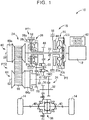
- FIG. 1 is a view illustrating the schematic configuration of a vehicle 10 to which the invention is applied.
- the vehicle 10 is equipped with a vehicular power transmission device 16 (hereinafter referred to as the power transmission device 16) that transmits a motive power of an engine 12 functioning as a motive power source to driving wheels 14.
- the power transmission device 16 transmits a motive power of an engine 12 functioning as a motive power source to driving wheels 14.
- the power transmission device 16 is provided between the engine 12 and the driving wheels 14.
- the power transmission device 16 is equipped with a known torque converter 20 as a hydraulic transmission device that is coupled to the engine 12, an input shaft 22 that is coupled to the torque converter 20, a belt-type continuously variable transmission 24 that is coupled to the input shaft 22, a forward/backward changeover device 26 that is also coupled to the input shaft 22, a gear mechanism 28 that is coupled to the input shaft 22 via the forward/backward changeover device 26 and that is provided in parallel with the continuously variable transmission 24, an output shaft 30 as an output rotary member that is common to the continuously variable transmission 24 and the gear mechanism 28, a countershaft 32, a reduction gear device 34 that is constituted of a pair of gears that are provided on the output shaft 30 and the countershaft 32 respectively in a relatively unrotatable manner and that mesh with each other, a gear 36 that is provided on the countershaft 32 in a relatively unrotatable manner, a differential device 38 that is coupled to the gear 36 in such a manner as to enable transmission of the motive
- the motive power output from the engine 12 is transmitted to the right and left driving wheels 14 sequentially via the torque converter 20, the forward/backward changeover device 26, the gear mechanism 28, the reduction gear device 34, the differential device 38, the axles 40 and the like.
- the motive power output from the engine 12 is transmitted to the right and left driving wheels 14 sequentially via the torque converter 20, the continuously variable transmission 24, the reduction gear device 34, the differential device 38, the axles 40 and the like.
- the motive power is synonymous with a torque or a power when they are not distinguished from each other in particular.
- the power transmission device 16 is equipped with the gear mechanism 28 and the continuously variable transmission 24, which are provided in parallel with the power transmission path PT between the engine 12 and the driving wheels 14.
- the power transmission device 16 is equipped with two power transmission paths that are provided in parallel with each other between the input shaft 22 and the output shaft 30 and that each enable transmission of the motive power of the engine 12 from the input shaft 22 to the output shaft 30.
- the two power transmission paths are a first power transmission path PT1 that is configured to include the gear mechanism 28, and a second power transmission path PT2 that is configured to include the continuously variable transmission 24. That is, the power transmission device 16 is equipped with the two power transmission paths, namely, the first power transmission path PT1 and the second power transmission path PT2, in parallel with each other between the input shaft 22 and the output shaft 30.
- the first power transmission path PT1 is a power transmission path that is equipped with the forward/backward changeover device 26 that is configured to include a first clutch C1 and a first brake B1, the gear mechanism 28, and a two-way clutch TWC functioning as a secondary clutch, and that ensures that the motive power of the engine 12 is transmitted from the input shaft 22 to the driving wheels 14 via the gear mechanism 28.
- the forward/backward changeover device 26, the gear mechanism 28, and the two-way clutch TWC are arranged in this sequence from the engine 12 toward the driving wheels 14.
- the two-way clutch TWC is arranged on the driving wheel 14 sides with respect to the first clutch C1.
- the second power transmission path PT2 is a power transmission path that is equipped with the continuously variable transmission 24 and a second clutch C2, and that ensures that the motive power of the engine 12 is transmitted from the input shaft 22 to the driving wheels 14 via the continuously variable transmission 24.
- the continuously variable transmission 24 and the second clutch C2 are arranged in this sequence from the engine 12 toward the driving wheels 14.
- the continuously variable transmission 24 that constitutes the second power transmission path PT2 is equipped with a primary shaft 58 that is provided coaxially with the input shaft 22 and that is integrally coupled to the input shaft 22, a primary pulley 60 that is coupled to the primary shaft 58 and whose effective diameter is variable, a secondary shaft 62 that is provided coaxially with the output shaft 30, a secondary pulley 64 that is coupled to the secondary shaft 62 and whose effective diameter is variable, and a transmission belt 66 as a transmission element that is wound between the respective pulleys 60 and 64.
- the continuously variable transmission 24 is a known belt-type continuously variable transmission that carries out the transmission of the motive power via a frictional force between each of the pulleys 60 and 64 and the transmission belt 66.
- the continuously variable transmission 24 transmits the motive power of the engine 12 to the driving wheel 14 sides.
- the effective diameter of the primary pulley 60 is changed by a hydraulic actuator 60a
- the effective diameter of the secondary pulley 64 is changed by a hydraulic actuator 64a.
- a speed ratio ycvt of the continuously variable transmission 24 is adjusted.
- a higher speed ratio is formed in the second power transmission path PT2 than in the first power transmission path PT1.
- the input shaft rotational speed Nin is a rotational speed of the input shaft 22
- the output shaft rotational speed Nout is a rotational speed of the output shaft 30.
- the power transmission device 16 In the power transmission device 16, the power transmission path through which the motive power of the engine 12 is transmitted to the driving wheels 14 is changed over between the first power transmission path PT1 and the second power transmission path PT2 in accordance with the running state of the vehicle 10. Therefore, the power transmission device 16 is equipped with a plurality of engagement devices for selectively forming the first power transmission path PT1 and the second power transmission path PT2.
- the plurality of the engagement devices correspond to the first clutch C1, the first brake B1, the second clutch C2, and the two-way clutch TWC.
- the first clutch C1 is an engagement device that is provided on the first power transmission path PT1 and that is designed to selectively connect and disconnect the first power transmission path PT1, and is an engagement device that enables the transmission of the motive power through the first power transmission path PT1 by being engaged when the vehicle runs forward.
- the first brake B1 is an engagement device that is provided on the first power transmission path PT1 and that is designed to selectively connect and disconnect the first power transmission path PT1, and is an engagement device that enables the transmission of the motive power through the first power transmission path PT1 by being engaged when the vehicle runs backward.
- the first power transmission path PT1 is formed through engagement of the first clutch C1 or the first brake B1.
- the second clutch C2 is an engagement device that is provided in the second power transmission path PT2 and that is designed to selectively connect and disconnect the second power transmission path PT2, and is an engagement device that enables the second power transmission path PT2 to transmit the motive power by being engaged when the vehicle runs forward.
- Each of the first clutch C1, the first brake B1, and the second clutch C2 is a known hydraulic wet frictional engagement device that is frictionally engaged by a hydraulic actuator.
- Each of the first clutch C1 and the first brake B1 is an element that constitutes the forward/backward changeover device 26.
- the two-way clutch TWC is provided in the first power transmission path PT1, and is configured to be changeable over between a one-way mode in which a motive power acting in a vehicle forward direction is transmitted and a motive power acting in a vehicle backward direction is blocked, and a lock mode in which the power acting in the vehicle forward direction and the motive power acting in the vehicle backward direction are transmitted.
- the vehicle forward direction corresponds to the normal rotation direction of the invention
- the vehicle backward direction corresponds to the reverse rotation direction of the invention.
- the one-way mode corresponds to the first mode of the invention
- the lock mode corresponds to the second mode of the invention.
- the motive power acting in the vehicle forward direction is transmitted to the two-way clutch TWC from the engine 12 with the two-way clutch TWC changed over to the one-way mode
- the motive power is transmitted to the driving wheels 14 via the two-way clutch TWC.
- the motive power acting in the vehicle backward direction is transmitted to the two-way clutch TWC from the engine 12 with the two-way clutch TWC changed over to the one-way mode
- the motive power is blocked by the two-way clutch TWC.
- the engine 12 is equipped with an engine control device 42 having various pieces of equipment that are needed to perform output control of the engine 12, such as an electronic throttle device, a fuel injection device, an ignition device and the like.
- the engine control device 42 of the engine 12 is controlled in accordance with an accelerator operation amount ⁇ acc as an operation amount of the accelerator pedal corresponding to an amount of a driving request made by a driver for the vehicle 10, by an electronic control unit (not shown).
- an engine torque Te as an output torque of the engine 12 is controlled.
- the torque converter 20 is equipped with a pump impeller 20p that is provided between the engine 12 and the continuously variable transmission 24 and that is coupled to the engine 12, and a turbine impeller 20t that is coupled to the input shaft 22.
- the torque converter 20 is a fluid transmission device that transmits the motive power of the engine 12 to the input shaft 22.
- the torque converter 20 is equipped with a known lockup clutch LU that can directly couple the pump impeller 20p and the turbine impeller 20t, namely, input and output rotary members of the torque converter 20 to each other.
- the lockup clutch LU directly couples the pump impeller 20p and the turbine impeller 20t (i.e., the engine 12 and the input shaft 22) to each other in accordance with a running state of the vehicle. For example, in a relatively high vehicle speed range, the engine 12 and the input shaft 22 are directly coupled to each other by the lockup clutch LU.
- the power transmission device 16 is equipped with a mechanical oil pump 44 that is coupled to the pump impeller 20p.
- the oil pump 44 supplies an original pressure of a working fluid pressure for performing shift control of the continuously variable transmission 24, generating a belt clamping force in the continuously variable transmission 24, changing over an operation state such as engagement, release and the like of each of the plurality of the engagement devices, and changing over an operation state of the lockup clutch LU to an oil pressure control circuit (not shown) with which the vehicle 10 is equipped.
- the forward/backward changeover device 26 is equipped with a double pinion-type planetary gear device 26p, the first clutch C1, and the first brake B1.
- the planetary gear device 26p is a differential mechanism having three rotary elements, namely, a carrier 26c as an input element, a sun gear 26s as an output element, and a ring gear 26r as a reaction element.
- the carrier 26c is coupled to the input shaft 22.
- the ring gear 26r is selectively coupled to the case 18 via the first brake B1.
- the sun gear 26s is coupled to a small-diameter gear 48 that is arranged on an outer peripheral side of the input shaft 22 and that is provided in such a manner as to enable rotation relative to the input shaft 22.
- the carrier 26c and the sun gear 26s are selectively coupled to each other via the first clutch C1.
- the gear mechanism 28 is equipped with the small-diameter gear 48, a countershaft 50, and a large-diameter gear 52 that is provided on the countershaft 50 in such a manner as to enable rotation relative thereto and that meshes with the small-diameter gear 48.
- a counter gear 54 that meshes with an output gear 56 provided on the output shaft 30 is provided on the countershaft 50 unrotatably relatively thereto.
- the countershaft 50 corresponds to the rotary shaft of the invention.
- the two-way clutch TWC is provided between the large-diameter gear 52 and the counter gear 54 in an axial direction of the countershaft 50.
- the two-way clutch TWC is provided on the driving wheel 14 sides with respect to the gear mechanism 28, in the first power transmission path PT1.
- the two-way clutch TWC is configured to be changeable over to one of the one-way mode and the lock mode, by a hydraulic actuator 41.
- FIG. 2 is a cross-sectional view for illustrating the structures of the two-way clutch TWC and the hydraulic actuator 41 for changing over the mode of the two-way clutch TWC.
- the countershaft 50 is arranged rotatably around an axis CL of rotation.
- Both the two-way clutch TWC and the hydraulic actuator 41 are arranged on the countershaft 50 as the rotary shaft. That is, the two-way clutch TWC and the hydraulic actuator 41 are arranged concentrically with the countershaft 50.
- the two-way clutch TWC and the hydraulic actuator 41 are provided on an outer peripheral side of the countershaft 50.
- the large-diameter gear 52, the counter gear 54, the two-way clutch TWC, and the hydraulic actuator 41 are substantially symmetric with respect to the axis CL of rotation. Therefore, a lower-half below the axis CL of rotation is omitted in FIG. 2 .
- the large-diameter gear 52 is formed in the shape of a circular disc, and is relatively rotatably fitted to an outer periphery of the countershaft 50 via a bearing 75. Meshing teeth 52a of the large-diameter gear 52 that meshes with the small-diameter gear 48 are formed on an outer peripheral side of the large-diameter gear 52. Besides, an inner peripheral side of the large-diameter gear 52 functions as a later-described input-side rotary member 68 that constitutes the two-way clutch TWC. That is, the large-diameter gear 52 and the input-side rotary member 68 of the two-way clutch TWC are integrally molded.
- the counter gear 54 is annularly formed, and an inner peripheral portion of the counter gear 54 is fixed to an outer peripheral surface of the countershaft 50 relatively unrotatably and relatively immovably in the axial direction.
- the counter gear 54 corresponds to the gear of the invention.
- the two-way clutch TWC is configured to include the input-side rotary member 68 that is formed on the inner peripheral side of the large-diameter gear 52, a first output-side rotary member 70a and a second output-side rotary member 70b that are arranged at a position that is adjacent to the input-side rotary member 68 in the axial direction of the countershaft 50 (it will be assumed hereinafter that the axial direction corresponds to the axial direction of the countershaft 50 unless otherwise specified), a plurality of first struts 72a and a plurality of torsion coil springs 73a that are interposed between the input-side rotary member 68 and the first output-side rotary member 70a in the axial direction, and a plurality of second struts 72b and a plurality of torsion coil springs 73b that are interposed between the input-side rotary member 68 and the second output-side rotary member 70b in the axial direction.
- each of the first output-side rotary member 70a and the second output-side rotary member 70b corresponds to the output-side rotary member of the invention.
- the input-side rotary member 68 is formed in the shape of a circular disc, and is arranged rotatably around the axis CL of rotation relatively to the countershaft 50.
- the input-side rotary member 68 is arranged in such a manner as to be sandwiched between the first output-side rotary member 70a and the second output-side rotary member 70b in the axial direction.
- the meshing teeth 52a of the large-diameter gear 52 are formed on an outer peripheral side of the input-side rotary member 68.
- the input-side rotary member 68 is coupled to the engine 12 in such a manner as to enable transmission of the motive power, via the gear mechanism 28, the forward/backward changeover device 26 and the like.
- First accommodation portions 76a in which the first struts 72a and the torsion coil springs 73a are accommodated respectively are formed in that surface of the input-side rotary member 68 which is opposed to the first output-side rotary member 70a in the axial direction. A plurality of the first accommodation portions 76a are formed at equal angular intervals in the circumferential direction.
- second accommodation portions 76b in which the second struts 72b and the torsion coil springs 73b are accommodated respectively are formed in that surface of the input-side rotary member 68 which is opposed to the second output-side rotary member 70b in the axial direction.
- a plurality of the second accommodation portions 76b are formed at equal angular intervals in the circumferential direction.
- the first accommodation portions 76a and the second accommodation portions 76b are formed at the same positions respectively in the radial direction of the input-side rotary member 68.
- the first output-side rotary member 70a is formed in the shape of a circular disc, and is arranged in such a manner as to be sandwiched between the bearing 75 and a bearing 67 in the axial direction. Besides, an inner peripheral portion of the first output-side rotary member 70a is spline-fitted to the countershaft 50, and the first output-side rotary member 70a thereby rotates integrally with the countershaft 50.
- the first output-side rotary member 70a is coupled to the driving wheels 14 in such a manner as to enable transmission of the motive power, via the counter gear 54, the output gear 56, the output shaft 30, the differential device 38, and the like.
- First recess portions 78a that are recessed away from the input-side rotary member 68 are formed in that surface of the first output-side rotary member 70a which is opposed to the input-side rotary member 68 in the axial direction.
- the first recess portions 78a thus formed are equal in number to the first accommodation portions 76a, and are arranged at equal angular intervals in the circumferential direction. Besides, each of the first recess portions 78a is formed at the same position as each of the first accommodation portions 76a formed in the input-side rotary member 68, in the radial direction of the first output-side rotary member 70a. Accordingly, when the rotational position of each of the first accommodation portions 76a and the rotational position of each of the first recess portions 78a coincide with each other, each of the first accommodation portions 76a and each of the first recess portions 78a are adjacent to each other in the axial direction (see FIG. 2 ).
- the second output-side rotary member 70b is an annular member with an L-shaped cross-section, and is arranged in such a manner as to be sandwiched, in the axial direction, between the bearing 75 and a flange portion 50a that protrudes in the radial direction from the outer peripheral surface of the countershaft 50. Besides, an inner peripheral portion of the second output-side rotary member 70b is spline-fitted to the countershaft 50, and the second output-side rotary member 70b thereby rotates integrally with the countershaft 50.
- the second output-side rotary member 70b is coupled to the driving wheels 14 in such a manner as to enable transmission of the motive power via the counter gear 54, the output gear 56, the output shaft 30, the differential device 38, and the like.
- Second recess portions 78b that are recessed away from the input-side rotary member 68 are formed in that surface of the second output-side rotary member 70b which is opposed to the input-side rotary member 68 in the axial direction.
- the second recess portions 78b thus formed are equal in number to the second accommodation portions 76b, and are arranged at equal angular intervals in the circumferential direction. Besides, each of the second recess portions 78b is formed at the same position as each of the second accommodation portions 76b formed in the input-side rotary member 68, in the radial direction of the second output-side rotary member 70b. Accordingly, when the rotational position of each of the second accommodation portions 76b and the rotational position of each of the second recess portions 78b coincide with each other, each of the second accommodation portions 76b and each of the second recess portions 78b are adjacent to each other in the axial direction (see FIG. 2 ).
- a plurality of through-holes 88 that are parallel to the axis CL of rotation are formed through the second output-side rotary member 70b.
- the through-holes 88 penetrate the second output-side rotary member 70b in the axial direction.
- each of the through-holes 88 is formed at a position overlapping with each of the second recess portions 78b when viewed in the axial direction of the countershaft 50. Accordingly, one end of each of the through-holes 88 communicates with each of the second recess portions 78b.
- Pins 90 are inserted through the through-holes 88 respectively.
- Each of the pins 90 is formed in the shape of a circular cylinder, and can slide within each of the through-holes 88.
- each of the pins 90 is held in abutment on a later-described pressing piston 74 that constitutes the hydraulic actuator 41, and the other end of each of the pins 90 is held in abutment on each of annular rings 86 that are accommodated in the second recess portions 78b respectively.
- the rings 86 are fitted to a plurality of arc-like grooves 84 (see FIGS. 3 and 4 ) that are formed in the second output-side rotary member 70b and that are formed in such a manner as to join the second recess portions 78b that are adjacent to each other in the circumferential direction (see FIGS. 3 and 4 ), and are movable relatively to the second output-side rotary member 70b in the axial direction. Accordingly, as shown in FIG. 2 , when each of the pins 90 moves toward the input-side rotary member 68 side in the axial direction by being pressed by the pressing piston 74, each of the rings 86 also moves toward the input-side rotary member 68 side in the axial direction by being pressed by each of the pins 90.
- each of the pins 90 shown in FIG. 2 moved to the utmost toward the input-side rotary member 68 side in the axial direction, an end portion of each of the rings 86 in the axial direction is moved to a position of a mating surface of the input-side rotary member 68 and the second output-side rotary member 70b.
- each of the second struts 72b accommodated in each of the second accommodation portions 76b is pressed by each of the rings 86, and each of the second struts 72b is thereby kept from moving toward each of the second recess portion 78b sides.
- the state shown in FIG. 2 corresponds to the state of the one-way mode of the two-way clutch TWC.
- Each of the pins 90 is moved in the axial direction by the hydraulic actuator 41.
- the hydraulic actuator 41 is arranged on the countershaft 50.
- the hydraulic actuator 41 is provided at a position that is adjacent to the second output-side rotary member 70b of the two-way clutch TWC in the axial direction, between the counter gear 54 and the two-way clutch TWC in the axial direction.
- the hydraulic actuator 41 is equipped with the pressing piston 74, a plurality of coil springs 92 that are interposed between the counter gear 54 and the pressing piston 74 in the axial direction, and a hydraulic chamber 94 that is formed by being surrounded by the pressing piston 74 and the countershaft 50.
- the pressing piston 74 is formed in the shape of a circular cylinder, and an inner peripheral surface of the pressing piston 74 is slidably fitted to the outer peripheral surface of the countershaft 50.
- a pair of O-rings 96 and 98 are interposed between the inner peripheral surface of the pressing piston 74 and the outer peripheral surface of the countershaft 50. Accordingly, the hydraulic chamber 94, which is formed between the pair of the O-rings 96 and 98 in the axial direction, is an oil-tight space.
- a flange portion 74a that extends in the radial direction is formed on the pressing piston 74 on the second output-side rotary member 70b side in the axial direction.
- the flange portion 74a extends in the radial direction as far as a position at which the flange portion 74a can abut on each of the pins 90 in the axial direction.
- the plurality of the coil springs 92 are interposed between the flange portion 74a of the pressing piston 74 and the counter gear 54 in the axial direction.
- the coil springs 92 are arranged at equal angular intervals in the circumferential direction of the pressing piston 74.
- Each of the coil springs 92 urges the pressing piston 74 toward the second output-side rotary member 70b side in the axial direction. Accordingly, with no working fluid supplied to the hydraulic chamber 94, the pressing piston 74 is moved toward the second output-side rotary member 70b side in the axial direction, and the flange portion 74a of the pressing piston 74 is brought into contact with the second output-side rotary member 70b, due to the urging force of the coil springs 92, as shown in FIG.
- the coil springs 92 are arranged at equal angular intervals in the circumferential direction of the pressing piston 74 (the flange portion 74a), so the urging force is substantially homogeneously applied to the pressing piston 74 in the circumferential direction.
- the coil springs 92 that are arranged at equal angular intervals in the circumferential direction substantially homogeneously urge the urging force to the pressing piston 74 in the circumferential direction.
- the pressing piston 74 is restrained from inclining.
- the oil pressure of working fluid homogeneously acts on the pressing piston 74 in the circumferential direction. Therefore, the pressing piston 74 is restrained from inclining.
- the pressing piston 74 is restrained from inclining, so there is no need to provide a mechanism for restraining the pressing piston 74 from inclining, a sensor for detecting the inclination of the pressing piston 74, and the like.
- the urging force of the coil springs 92 acts as a load for moving the pressing piston 74 toward the second output-side rotary member 70b side in the axial direction in the hydraulic actuator 41, and a force generated by the oil pressure of working fluid in the hydraulic chamber 94 acts as a load for moving the pressing piston 74 toward the counter gear 54 side in the axial direction in the hydraulic actuator 41.
- the hydraulic actuator 41 is arranged on the countershaft 50 as is the case with the two-way clutch TWC. Therefore, the hydraulic actuator 41 can be configured to be adjacent to the two-way clutch TWC in the axial direction. By aggregating members constituting the hydraulic actuator 41 at a position that is adjacent to the two-way clutch TWC, the hydraulic actuator 41 can be compactly configured. Besides, one end of each of the coil springs 92 is held in abutment on the counter gear 54, and the counter gear 54 is used as a member that receives a reaction force of the coil springs 92. Thus, the number of parts is restrained from increasing, and the hydraulic actuator 41 is compact.
- FIGS. 3 and 4 are cross-sectional views showing part of the two-way clutch TWC of FIG. 2 cut off along the circumferential direction thereof at a position indicated by an alternate long and short dash line A.
- FIG. 3 shows a state where the two-way clutch TWC has been changed over to the one-way mode
- FIG. 4 shows a state where the two-way clutch TWC has been changed over to the lock mode.
- a vertical direction on the sheet of each of FIGS. 3 and 4 corresponds to a rotational direction
- an upward direction on the sheet corresponds to the vehicle backward direction (a backward rotational direction)
- a downward direction on the sheet corresponds to the vehicle forward direction (a forward rotational direction).
- a lateral direction on the sheet of each of FIGS. 3 and 4 corresponds to the axial direction of the countershaft 50 (i.e., the direction of the axis CL of rotation), a right side on the sheet corresponds to the large-diameter gear 52 side of FIG. 2 , and a left side on the sheet corresponds to the counter gear 54 side of FIG. 2 .
- each of the first accommodation portions 76a in which each of the first struts 72a and the each of the torsion coil springs 73a are accommodated is formed on that side of the input-side rotary member 68 which is opposed to the first output-side rotary member 70a in the axial direction (in the lateral direction on the sheet).
- Each of the first struts 72a is configured as a plate-like member having a predetermined thickness, and is formed lengthwise along the rotational direction (the circumferential direction) as indicated by the cross-sections of FIGS. 3 and 4 .
- each of the first struts 72a has a predetermined dimension in a direction perpendicular to the sheet of each of FIGS. 3 and 4 (the radial direction in FIG. 2 ).
- each of the first struts 72a in a longitudinal direction thereof is urged toward the first output-side rotary member 70a side by each of the torsion coil springs 73a.
- the other end of each of the first struts 72a in the longitudinal direction thereof is held in abutment on each of first step portions 82a formed in the first accommodation portions 76a.
- Each of the first struts 72a can turn around the other end thereof that abuts on each of the first step portions 82a.
- Each of the torsion coil springs 73a is interposed between each of the first struts 72a and the input-side rotary member 68, and urges one end of each of the first struts 72a toward the first output-side rotary member 70a.
- the first recess portions 78a that are recessed in the direction away from the input-side rotary member 68 are formed in that surface of the first output-side rotary member 70a which is opposed to the input-side rotary member 68 in the axial direction.
- Each of the first recess portions 78a is shaped such that one end of each of the first struts 72a can be accommodated therein.
- the above-mentioned first struts 72a, the above-mentioned torsion coil springs 73a, the above-mentioned first accommodation portions 76a, and the above-mentioned first recess portions 78a constitute the one-way clutch that transmits the motive power acting in the vehicle forward direction to the driving wheels 14 and that blocks the motive power acting in the vehicle backward direction.
- the second accommodation portions 76b in which the second struts 72b and the torsion coil springs 73b are accommodated are formed in that surface of the input-side rotary member 68 which is opposed to the second output-side rotary member 70b in the axial direction.
- Each of the second struts 72b is configured as a plate-like member having a predetermined thickness, and is formed in the longitudinal direction along the rotational direction as indicated by the cross-sections of FIGS. 3 and 4 .
- each of the second struts 72b has a predetermined dimension in the direction perpendicular to the sheet of each of FIGS. 3 and 4 (the radial direction in FIG. 2 ).
- each of the second struts 72b in the longitudinal direction thereof is urged toward the second output-side rotary member 70b side by each of the torsion coil springs 73b.
- the other end of each of the second struts 72b in the longitudinal direction thereof is held in abutment on each of second step portions 82b formed in the second accommodation portions 76b respectively.
- Each of the second struts 72b can turn around the other end thereof that abuts on each of the second step portions 82b.
- Each of the torsion coil springs 73b is interposed between each of the second struts 72b and the input-side rotary member 68, and urges one end of each of the second struts 72b toward the second output-side rotary member 70b.
- the second recess portions 78b that are recessed in the direction away from the input-side rotary member 68 are formed in that surface of the second output-side rotary member 70b which is opposed to the input-side rotary member 68 in the axial direction.
- Each of the second recess portions 78b is shaped such that one end of each of the second struts 72b can be accommodated therein.
- the above-mentioned second struts 72b, the above-mentioned torsion coil springs 73b, the above-mentioned second accommodation portions 76b, and the above-mentioned second recess portions 78b constitute the one-way clutch that transmits the motive power acting in the vehicle backward direction to the driving wheels 14 and that blocks the motive power acting in the vehicle forward direction.
- the through-holes 88 that penetrate in the axial direction are formed through the second output-side rotary member 70b, and the pins 90 are inserted through these through-holes respectively.
- One end of each of the pins 90 abuts on the pressing piston 74, and the other end of each of the pins 90 abuts on each of the annular rings 86.
- the pressing piston 74 is urged toward the second output-side rotary member 70b side by the coil springs 92.
- each of the pins 90 is moved toward the input-side rotary member 68 side by being pressed by the pressing piston 74, and each of the rings 86 is also moved toward the input-side rotary member 68 side in the axial direction by being pressed by each of the pins 90.
- one end of each of the second struts 72b moves toward the input-side rotary member 68 side by being pressed against each of the rings 86.
- each of the second struts 72b and each of the second wall surfaces 80b are kept from abutting on each other.
- the input-side rotary member 68 and the second output-side rotary member 70b are allowed to rotate relatively to each other, so the second struts 72b do not function as the one-way clutch.
- one end of each of the first struts 72a is urged toward the first output-side rotary member 70a side by each of the torsion coil springs 73a, and can hence abut on each of the first wall surfaces 80a of the first recess portions 78a. That is, in the state shown in FIG. 3 , the input-side rotary member 68 and the first output-side rotary member 70a are kept from rotating relatively to each other in the vehicle forward direction.
- each of the first struts 72a can abut on each of the first wall surfaces 80a of the first output-side rotary member 70a.
- the two-way clutch TWC in the one-way mode, each of the first struts 72a can abut on each of the first wall surfaces 80a of the first output-side rotary member 70a.
- the two-way clutch TWC in the one-way mode, one end of each of the first struts 72a and one of the first wall surfaces 80a abut on each other, and the other end of each of the first struts 72a and each of the first step portions 82a abut on each other, as shown in FIG. 3 .
- the input-side rotary member 68 and the first output-side rotary member 70a are kept from rotating relatively to each other in the vehicle forward direction.
- the first struts 72a function as the one-way clutch, transmit the motive power acting in the vehicle forward direction to the driving wheels 14, and block the motive power acting in the vehicle backward direction.
- the two-way clutch TWC can transmit the motive power acting in the vehicle forward direction and the motive power acting in the vehicle backward direction to the driving wheels 14. Accordingly, for example, when the vehicle runs backward, the changeover of the two-way clutch TWC to the lock mode enables the vehicle to run backward. Besides, when the vehicle coasts, the rotation transmitted from the driving wheel 14 sides is transmitted to the engine 12 side via the two-way clutch TWC by changing over the two-way clutch TWC to the lock mode. Thus, engine braking through the dragging of the engine 12 can be caused.
- the two-way clutch TWC is set in such a manner as to be changed over to the one-way mode due to the urging force of the coil springs 92. Accordingly, when the vehicle runs with the two-way clutch TWC in the one-way mode, there is no need to supply working fluid to the hydraulic actuator 41.
- the operation of the power transmission device 16 configured as described above will be described.
- a changeover to gear running for causing the vehicle 10 to run by transmitting the motive power of the engine 12 to the driving wheels 14 via the first power transmission path PT1 is made.
- the first clutch C1 is engaged, the second clutch C2 is released, and the two-way clutch TWC is changed over to the one-way mode.
- the motive power of the engine 12 is transmitted to the first power transmission path PT1 side.
- the two-way clutch TWC is changed over to the one-way mode, and hence can transmit the motive power acting in the vehicle forward direction.
- gear running for transmitting the motive power of the engine 12 to the driving wheels 14 via the first power transmission path PT1 is enabled.
- the dog clutch is provided instead of the two-way clutch TWC, and the rotation transmitted to the first clutch C1 is blocked by disconnecting this dog clutch.
- the dog clutch needs to be disconnected every time a changeover from gear running to belt running is made.
- the two-way clutch TWC is applied.
- the running mode is changed from gear running to belt running, namely, the power transmission path PT is changed over from the first power transmission path PT1 to the second power transmission path PT2.
- a changeover from gear running to belt running is made by controlling the torque capacity of the second clutch C2.
- the two-way clutch TWC transmits the motive power to the first power transmission path PT1 at an appropriate timing, so a shock is restrained from being caused in the changeover transition period.
- the changeover of the power transmission path PT is carried out only through the control of the torque capacity of the second clutch C2.
- the control is easier to perform than in the case where clutch-to-clutch control of the first clutch C1 and the second clutch C2 is performed.
- the vehicle runs backward
- the first brake B1 is engaged, and the two-way clutch TWC is changed over to the lock mode.
- the motive power acting in the vehicle backward direction is transmitted to the first power transmission path PT1.
- the motive power acting in the vehicle backward direction is transmitted to the driving wheels 14 via the two-way clutch TWC, by changing over the two-way clutch TWC to the lock mode. Therefore, the vehicle is enabled to run backward.
- the mode of the two-way clutch TWC is changed over in the power transmission device 16.
- the vehicle 10 is enabled to run forward and backward.
- engine braking can also be caused when the vehicle coasts.
- the rotation transmitted from the driving wheel 14 sides is blocked by the two-way clutch TWC, by changing over the two-way clutch TWC to the one-way mode during belt running.
- the members and the like that constitute the first clutch C1 located on the engine 12 side with respect to the two-way clutch TWC are prevented from rotating at high speed.
- the vehicle is enabled to run in the same manner as in the case where the dog clutch having the synchronization mechanism is provided instead of the two-way clutch TWC.
- the two-way clutch TWC is not equipped with any synchronization mechanism.
- the number of parts of the two-way clutch TWC is smaller than the number of parts of the dog clutch that is equipped with the synchronization mechanism, and the cost of manufacturing the two-way clutch TWC has been reduced below the cost of manufacturing the dog clutch.
- the two-way clutch TWC that can be changed over to the one-way mode and the lock mode is provided as the secondary clutch. Therefore, for example, by changing over the two-way clutch TWC to the one-way mode, the motive power acting in the vehicle forward direction can be transmitted in the first power transmission path PT1. Besides, by changing over the two-way clutch TWC to the lock mode, the motive power acting in the vehicle backward direction can be transmitted in the first power transmission path PT1. Besides, by changing over the two-way clutch TWC to the one-way mode while the vehicle runs through the use of the second power transmission path PT2, the rotation transmitted from the driving wheel 14 sides can be blocked by the two-way clutch TWC.
- the first clutch C1 and the like which are located on the engine side with respect to the two-way clutch TWC, are prevented from rotating at high speed.
- the vehicle is enabled to run forward and backward via the first power transmission path PT1, and the first clutch C1 is prevented from rotating at high speed.
- the vehicle can run in the same manner as in the case where the dog clutch having the synchronization mechanism is provided as the secondary clutch in the first power transmission path PT1.
- the two-way clutch TWC does not require any synchronization mechanism. Therefore, the number of parts is smaller, and the cost of manufacturing can be further reduced than in the case where the dog clutch having the synchronization mechanism is provided in the first power transmission path PT1.
- the hydraulic actuator 41 for changing over the mode of the two-way clutch TWC is arranged on the countershaft 50 as is the case with the two-way clutch TWC. Therefore, the hydraulic actuator 41 can be compactly configured by aggregating parts constituting the hydraulic actuator 41 at a position that is adjacent to the two-way clutch TWC. Besides, the two-way clutch TWC changes over to the one-way mode with no working fluid supplied to the hydraulic actuator 41, so there is no need to supply working fluid to the hydraulic actuator 41 while the vehicle runs in the one-way mode. As a result, the amount of consumption of working fluid can be reduced. Besides, the coil springs 92 that constitute the hydraulic actuator 41 are interposed between the pressing piston 74 and the counter gear 54. Therefore, the number of parts can be restrained from increasing, by utilizing the counter gear 54 as a member for generating the reaction force of the coil springs 92.
- FIG. 5 is a view illustrating the schematic configuration of a vehicle 120 corresponding to another one of the embodiments of the invention.
- a vehicle power transmission device 122 (hereinafter referred to as the power transmission device 122) is provided between the engine 12 and the driving wheels 14.
- a comparison between the power transmission device 122 and the power transmission device 16 according to the foregoing first embodiment reveals that the former is different in the structure of a forward/backward changeover device 126 from the latter.
- the structure of the forward/backward changeover device 126 that is different from that of the foregoing first embodiment will be described hereinafter.
- the forward/backward changeover device 126 is equipped with a double pinion-type planetary gear device 126p, the first clutch C1, and the first brake B1.
- the planetary gear device 126p is a differential mechanism having three rotary elements, namely, a sun gear 126s as an input element, a carrier 126c as an output element, and a ring gear 126r as a reaction element.
- the sun gear 126s is coupled to the input shaft 22.
- the ring gear 126r is selectively coupled to the case 18 via the first brake B1.
- the carrier 126c is coupled to the small-diameter gear 48.
- the carrier 126c and the sun gear 126s are selectively coupled to each other via the first clutch C1.
- the motive of the engine 12 is transmitted, as the motive power acting in the vehicle forward direction, to the small-diameter gear 48 via the carrier 126c when the first clutch C1 is engaged, and the motive power of the engine 12 is transmitted, as the motive power acting in the vehicle backward direction, to the small-diameter gear 48 via the carrier 126c when the first brake B1 is engaged. Accordingly, even in the case where the forward/backward changeover device 126 is configured as described above, the vehicle 10 can be caused to run in the same manner as in the foregoing embodiment.
- the forward/backward changeover device 126 of the present embodiment also makes it possible to obtain an effect similar to that of the foregoing embodiment.
- the forward/backward changeover device 126 is configured as the double pinion-type planetary gear device as is the case with the forward/backward changeover device 26 of the foregoing embodiment.
- the invention is applicable even if the forward/backward changeover device is configured as a single pinion-type planetary gear device.
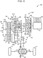
- FIG. 6 is a view illustrating the schematic configuration of a vehicle 140 corresponding to still another one of the embodiments of the invention.
- a vehicle power transmission device 142 (hereinafter referred to as the power transmission device 142) is provided between the engine 12 and the driving wheels 14.
- a comparison between the power transmission device 142 and the power transmission device 16 according to the foregoing first embodiment reveals that the former is different from the latter in location where the two-way clutch TWC is arranged.
- the two-way clutch TWC is arranged on the same rotary shaft as the input shaft 22. What is different from the foregoing first embodiment will be described hereinafter.
- the two-way clutch TWC is arranged on the same rotary shaft as the input shaft 22.
- the two-way clutch TWC is interposed between the carrier 26c of the forward/backward changeover device 26 and the small-diameter gear 48, on an outer periphery of the input shaft 22. Accordingly, in the present embodiment, the forward/backward changeover device 26, the two-way clutch TWC, and the gear mechanism 28 are arranged in this sequence from the engine 12 side, in the first power transmission path PT1.
- the vehicle can run in the same manner as in the foregoing first embodiment.
- the vehicle when the vehicle runs forward, the vehicle is enabled to run forward through the motive power of the engine 12, by changing over the two-way clutch TWC to the one-way mode.
- the vehicle runs backward, the vehicle is enabled to run backward through the motive power of the engine 12, by changing over the two-way clutch TWC to the lock mode.
- the rotation of the driving wheels 14 is transmitted to the gear mechanism 28 by changing over the two-way clutch TWC to the one-way mode.
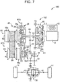
- FIG. 7 is a view illustrating the schematic configuration of a vehicle 160 corresponding to still another one of the embodiments of the invention.
- a vehicle power transmission device 162 (hereinafter referred to as the power transmission device 162) is provided between the engine 12 and the driving wheels 14.
- a comparison between the power transmission device 162 and the power transmission device 16 according to the foregoing first embodiment reveals that the former is different from the latter in location where the two-way clutch TWC is arranged.
- the two-way clutch TWC is arranged on the same rotary shaft as the output shaft 30. What is different from the foregoing first embodiment will be described hereinafter.
- the two-way clutch TWC is arranged on the same rotary shaft as the output shaft 30.
- the two-way clutch TWC is interposed between the output gear 56 and the output shaft 30, on an outer periphery of the output shaft 30.
- the vehicle is enabled to run in the same manner as in the foregoing first embodiment. For example, when the vehicle runs forward, the vehicle is enabled to run forward through the power of the engine 12, by changing over the two-way clutch TWC to the one-way mode. When the vehicle runs backward, the vehicle is enabled to run backward through the motive power of the engine 12, by changing over the two-way clutch TWC to the lock mode.
- FIG. 8 is a view illustrating the schematic configuration of a vehicle 180 corresponding to still another one of the embodiments of the invention.
- a vehicle power transmission device 182 (hereinafter referred to as the power transmission device 182) is provided between the engine 12 and the driving wheels 14.
- a comparison between the power transmission device 182 and the power transmission device 16 according to the foregoing first embodiment reveals that the former is different from the latter in location where the second clutch C2 is arranged.
- the second clutch C2 is arranged on the same rotary shaft as the input shaft 22. What is different from the foregoing first embodiment will be described hereinafter.
- the second clutch C2 is provided between the input shaft 22 and the primary shaft 58 of the primary pulley 60. Accordingly, the second clutch C2 and the continuously variable transmission 24 are arranged in this sequence from the engine 12 side in the second power transmission path PT2.
- the vehicle is enabled to run in the same manner as in the foregoing embodiment.
- the second clutch C2 is arranged on the same rotary shaft as the input shaft 22, so the torque capacity of the second clutch C2 can be made smaller than in the case where the second clutch C2 is arranged on the same rotary shaft as the output shaft 30.
- the cost of manufacturing the second clutch C2 can be reduced, and the controllability of the second clutch C2 is also enhanced.
- the two-way clutch TWC is configured to be changeable over between the one-way mode in which the motive power acting in the vehicle forward direction is transmitted and the motive power acting in the vehicle backward direction is blocked, and the lock mode in which the motive power acting in the vehicle forward direction and the motive power acting in the vehicle backward direction are transmitted, but the invention is not necessarily limited thereto.
- a free mode in which the motive power in the vehicle forward direction and the motive power in the vehicle backward direction are blocked, and a mode in which only the motive power acting in the vehicle backward direction is transmitted may be added to the one-way mode and the lock mode.
- the structure of the two-way clutch TWC is not necessarily limited to that of the present embodiment.
- the two-way clutch may be constituted of a first one-way clutch and a second one-way clutch that are provided separately from each other, the first one-way clutch may be configured to be able to transmit the motive power acting in the vehicle forward direction, the second one-way clutch may be configured to be able to transmit the motive power acting in the vehicle backward direction, and furthermore, the second one-way clutch may be configured to be changeable over to a mode in which the motive power acting in the vehicle backward direction is blocked.
- the structure thereof can be changed as appropriate.
- the first one-way clutch may also be configured to be changeable over to a mode in which the motive power acting in the vehicle forward direction is blocked.
- the gear ratio EL in the first power transmission path PT1 that is constituted of the gear mechanism 28 is set as a value larger than the lowermost speed ratio ymax of the continuously variable transmission 24 as the maximum speed ratio in the second power transmission path PT2, but the invention is not necessarily limited thereto.
- the gear ratio EL may be set to a value smaller than the lowermost speed ratio ymax of the continuously variable transmission 24, namely, on the high side.
- the belt-type continuously variable transmission 24 is arranged on the second power transmission path PT2, but the invention is not necessarily limited to the belt-type continuously variable transmission.
- this belt-type continuously variable transmission can be replaced with a toroidal-type continuously variable transmission or the like as appropriate.
- the hydraulic actuator 41 is subjected to differential operation by the oil pressure of working fluid, but the actuator is not necessarily limited thereto.
- the actuator may be driven by an electric motor.
- the first struts 72a are arranged on the input-side rotary member 68, and the first recess portions 78a are formed in the first output-side rotary member 70a.
- the first recess portions 78a may be formed in the input-side rotary member 68, and the first struts 72a may be arranged on the first output-side rotary member 70a.
- the hydraulic actuator 41 is arranged between the counter gear 54 and the input-side rotary member 68.
- the hydraulic actuator 41 may be arranged on a back side of the counter gear 54 with respect to the input-side rotary member 68.
- the hydraulic actuator 41 is arranged adjacent to the second output-side rotary member 70b, the first struts 72a, which are interposed between the input-side rotary member 68 and the second output-side rotary member 70b, are configured to be changeable over by the hydraulic actuator 41, and the first struts 72a function as the one-way clutch that transmits the motive power acting in the vehicle backward direction and that blocks the motive power acting in the vehicle forward direction.
- the two-way clutch TWC when no working fluid is supplied to the hydraulic actuator 41, the two-way clutch TWC changes over to the one-way mode.
- the two-way clutch TWC may be configured to change over to the lock mode when no working fluid is supplied to the hydraulic actuator 41.
- the two-way clutch TWC can transmit the motive power acting in the vehicle forward direction and the motive power acting in the vehicle backward direction upon being changed over to the lock mode, but the invention is not necessarily limited thereto.
- the two-way clutch is only required to transmit the motive power acting in the vehicle backward direction, and may not necessarily transmit the motive power acting in the vehicle forward direction.
Landscapes
- Engineering & Computer Science (AREA)
- General Engineering & Computer Science (AREA)
- Mechanical Engineering (AREA)
- Chemical & Material Sciences (AREA)
- Combustion & Propulsion (AREA)
- Transportation (AREA)
- Structure Of Transmissions (AREA)
- Transmission Devices (AREA)
Applications Claiming Priority (1)
| Application Number | Priority Date | Filing Date | Title |
|---|---|---|---|
| JP2018195439A JP7040396B2 (ja) | 2018-10-16 | 2018-10-16 | 車両用動力伝達装置 |
Publications (2)
| Publication Number | Publication Date |
|---|---|
| EP3640500A1 true EP3640500A1 (fr) | 2020-04-22 |
| EP3640500B1 EP3640500B1 (fr) | 2022-06-22 |
Family
ID=67981945
Family Applications (1)
| Application Number | Title | Priority Date | Filing Date |
|---|---|---|---|
| EP19197527.5A Not-in-force EP3640500B1 (fr) | 2018-10-16 | 2019-09-16 | Dispositif de transmission de puissance pour véhicule |
Country Status (5)
| Country | Link |
|---|---|
| US (1) | US10989287B2 (fr) |
| EP (1) | EP3640500B1 (fr) |
| JP (1) | JP7040396B2 (fr) |
| KR (1) | KR102228710B1 (fr) |
| CN (1) | CN111059240A (fr) |
Families Citing this family (2)
| Publication number | Priority date | Publication date | Assignee | Title |
|---|---|---|---|---|
| JP7035952B2 (ja) * | 2018-10-16 | 2022-03-15 | トヨタ自動車株式会社 | 車両用動力伝達装置の制御装置 |
| CN118974447A (zh) * | 2022-04-04 | 2024-11-15 | 北极星工业有限公司 | 无级变速器 |
Citations (4)
| Publication number | Priority date | Publication date | Assignee | Title |
|---|---|---|---|---|
| EP1114952A1 (fr) * | 2000-01-07 | 2001-07-11 | Nissan Motor Co., Ltd. | Transmission à variation continue |
| WO2013176208A1 (fr) | 2012-05-23 | 2013-11-28 | トヨタ自動車株式会社 | Dispositif de transmission de puissance de véhicule |
| WO2014120595A1 (fr) * | 2013-01-30 | 2014-08-07 | Borgwarner Inc. | Module d'embrayage à modes multiples |
| US20180274643A1 (en) * | 2015-10-30 | 2018-09-27 | Aisin Aw Co., Ltd. | Automatic transmission |
Family Cites Families (12)
| Publication number | Priority date | Publication date | Assignee | Title |
|---|---|---|---|---|
| KR20010012128A (ko) | 1997-04-28 | 2001-02-15 | 민즈 인더스트리즈 인코포레이티드 | 제어가능한 오버런닝 커플링 |
| JP4183810B2 (ja) | 1998-10-23 | 2008-11-19 | 富士重工業株式会社 | 車両用ベルト式無段変速装置 |
| JP4440421B2 (ja) * | 2000-04-17 | 2010-03-24 | トヨタ自動車株式会社 | 電磁式ローラクラッチ |
| JP2002048213A (ja) * | 2000-08-01 | 2002-02-15 | Toyota Motor Corp | 無段変速機構を備えた変速機 |
| EP1519084A3 (fr) * | 2003-09-26 | 2012-05-02 | NTN Corporation | Boîte de vitesses de véhicule |
| US8286772B2 (en) | 2009-04-01 | 2012-10-16 | Means Industries, Inc. | Controllable coupling assembly and overrunning coupling and control assembly utilizing same |
| US8727090B2 (en) * | 2010-07-22 | 2014-05-20 | Tai-Her Yang | Centrifugal force combined with sliding damping type torque actuated clutch |
| DE102012006730B4 (de) * | 2012-04-02 | 2024-07-18 | Borgwarner Inc. | Kupplungseinrichtung |
| US9127730B2 (en) * | 2012-10-17 | 2015-09-08 | Magna Powertrain Of America, Inc. | Electric actuator module for selectable clutch |
| US10006498B2 (en) * | 2016-01-28 | 2018-06-26 | Deere & Company | Drive assembly with bimodal clutch module |
| JP6456420B2 (ja) | 2016-03-17 | 2019-01-23 | 本田技研工業株式会社 | 自動変速機 |
| WO2018085920A1 (fr) * | 2016-11-10 | 2018-05-17 | Magna Powertrain Inc. | Ensemble embrayage unidirectionnel électrique à double effet |
-
2018
- 2018-10-16 JP JP2018195439A patent/JP7040396B2/ja not_active Expired - Fee Related
-
2019
- 2019-09-05 US US16/561,095 patent/US10989287B2/en not_active Expired - Fee Related
- 2019-09-05 KR KR1020190110054A patent/KR102228710B1/ko not_active Expired - Fee Related
- 2019-09-10 CN CN201910852618.3A patent/CN111059240A/zh active Pending
- 2019-09-16 EP EP19197527.5A patent/EP3640500B1/fr not_active Not-in-force
Patent Citations (4)
| Publication number | Priority date | Publication date | Assignee | Title |
|---|---|---|---|---|
| EP1114952A1 (fr) * | 2000-01-07 | 2001-07-11 | Nissan Motor Co., Ltd. | Transmission à variation continue |
| WO2013176208A1 (fr) | 2012-05-23 | 2013-11-28 | トヨタ自動車株式会社 | Dispositif de transmission de puissance de véhicule |
| WO2014120595A1 (fr) * | 2013-01-30 | 2014-08-07 | Borgwarner Inc. | Module d'embrayage à modes multiples |
| US20180274643A1 (en) * | 2015-10-30 | 2018-09-27 | Aisin Aw Co., Ltd. | Automatic transmission |
Also Published As
| Publication number | Publication date |
|---|---|
| CN111059240A (zh) | 2020-04-24 |
| US10989287B2 (en) | 2021-04-27 |
| JP7040396B2 (ja) | 2022-03-23 |
| EP3640500B1 (fr) | 2022-06-22 |
| US20200116243A1 (en) | 2020-04-16 |
| KR102228710B1 (ko) | 2021-03-16 |
| KR20200042842A (ko) | 2020-04-24 |
| JP2020063774A (ja) | 2020-04-23 |
Similar Documents
| Publication | Publication Date | Title |
|---|---|---|
| CN100557271C (zh) | 自动变速器 | |
| US7731624B2 (en) | Automatic transmission | |
| US9970522B2 (en) | Automatic transmission | |
| EP3640505B1 (fr) | Dispositif de transmission de puissance pour véhicule et procédé de commande de dispositif de transmission de puissance | |
| US20170314672A1 (en) | Control apparatus for power transmission system | |
| EP3640500B1 (fr) | Dispositif de transmission de puissance pour véhicule | |
| US5813933A (en) | Continuously variable transmission with bias springs on the drive and driven pulleys for setting a predetermined speed ratio when the cut is in neutral | |
| US20190293129A1 (en) | Frictional coupling device of vehicular power transmitting system | |
| US20200114914A1 (en) | Control apparatus for vehicle drive-force transmitting apparatus | |
| EP3690284A1 (fr) | Dispositif de transmission d'alimentation de véhicule | |
| CN111071033A (zh) | 车辆用动力传递装置 | |
| JP6112068B2 (ja) | 噛合式クラッチ | |
| JP2008064125A (ja) | ベルト式無段変速機 | |
| JP4734972B2 (ja) | 歯車装置 | |
| US9625019B2 (en) | Infinitely variable transmission | |
| CN111075923A (zh) | 车辆用动力传递装置的控制装置 | |
| JP4792791B2 (ja) | トルクカム装置およびベルト式無段変速機 | |
| JP6474661B2 (ja) | 車両用動力伝達装置 | |
| JP2010276159A (ja) | 無段変速機 | |
| JP2021127808A (ja) | クラッチ機構 | |
| JP2021060053A (ja) | 車両用油圧シリンダ装置 | |
| KR19980049800A (ko) | 차량용 무단 변속장치 | |
| WO2019167426A1 (fr) | Dispositif de transmission de puissance | |
| JP2015045364A (ja) | 車両用変速機 | |
| JP2006300213A (ja) | トルクカム装置およびベルト式無段変速機 |
Legal Events
| Date | Code | Title | Description |
|---|---|---|---|
| PUAI | Public reference made under article 153(3) epc to a published international application that has entered the european phase |
Free format text: ORIGINAL CODE: 0009012 |
|
| STAA | Information on the status of an ep patent application or granted ep patent |
Free format text: STATUS: REQUEST FOR EXAMINATION WAS MADE |
|
| 17P | Request for examination filed |
Effective date: 20190927 |
|
| AK | Designated contracting states |
Kind code of ref document: A1 Designated state(s): AL AT BE BG CH CY CZ DE DK EE ES FI FR GB GR HR HU IE IS IT LI LT LU LV MC MK MT NL NO PL PT RO RS SE SI SK SM TR |
|
| AX | Request for extension of the european patent |
Extension state: BA ME |
|
| STAA | Information on the status of an ep patent application or granted ep patent |
Free format text: STATUS: EXAMINATION IS IN PROGRESS |
|
| 17Q | First examination report despatched |
Effective date: 20201201 |
|
| RIC1 | Information provided on ipc code assigned before grant |
Ipc: F16H 37/02 20060101AFI20210610BHEP Ipc: F16D 41/14 20060101ALI20210610BHEP |
|
| GRAP | Despatch of communication of intention to grant a patent |
Free format text: ORIGINAL CODE: EPIDOSNIGR1 |
|
| STAA | Information on the status of an ep patent application or granted ep patent |
Free format text: STATUS: GRANT OF PATENT IS INTENDED |
|
| INTG | Intention to grant announced |
Effective date: 20210802 |
|
| GRAJ | Information related to disapproval of communication of intention to grant by the applicant or resumption of examination proceedings by the epo deleted |
Free format text: ORIGINAL CODE: EPIDOSDIGR1 |
|
| STAA | Information on the status of an ep patent application or granted ep patent |
Free format text: STATUS: EXAMINATION IS IN PROGRESS |
|
| INTC | Intention to grant announced (deleted) | ||
| GRAP | Despatch of communication of intention to grant a patent |
Free format text: ORIGINAL CODE: EPIDOSNIGR1 |
|
| STAA | Information on the status of an ep patent application or granted ep patent |
Free format text: STATUS: GRANT OF PATENT IS INTENDED |
|
| INTG | Intention to grant announced |
Effective date: 20220125 |
|
| GRAS | Grant fee paid |
Free format text: ORIGINAL CODE: EPIDOSNIGR3 |
|
| GRAA | (expected) grant |
Free format text: ORIGINAL CODE: 0009210 |
|
| STAA | Information on the status of an ep patent application or granted ep patent |
Free format text: STATUS: THE PATENT HAS BEEN GRANTED |
|
| AK | Designated contracting states |
Kind code of ref document: B1 Designated state(s): AL AT BE BG CH CY CZ DE DK EE ES FI FR GB GR HR HU IE IS IT LI LT LU LV MC MK MT NL NO PL PT RO RS SE SI SK SM TR |
|
| REG | Reference to a national code |
Ref country code: GB Ref legal event code: FG4D |
|
| REG | Reference to a national code |
Ref country code: CH Ref legal event code: EP |
|
| REG | Reference to a national code |
Ref country code: DE Ref legal event code: R096 Ref document number: 602019016099 Country of ref document: DE |
|
| REG | Reference to a national code |
Ref country code: AT Ref legal event code: REF Ref document number: 1499966 Country of ref document: AT Kind code of ref document: T Effective date: 20220715 |
|
| REG | Reference to a national code |
Ref country code: IE Ref legal event code: FG4D |
|
| REG | Reference to a national code |
Ref country code: LT Ref legal event code: MG9D |
|
| REG | Reference to a national code |
Ref country code: NL Ref legal event code: MP Effective date: 20220622 |
|
| PG25 | Lapsed in a contracting state [announced via postgrant information from national office to epo] |
Ref country code: SE Free format text: LAPSE BECAUSE OF FAILURE TO SUBMIT A TRANSLATION OF THE DESCRIPTION OR TO PAY THE FEE WITHIN THE PRESCRIBED TIME-LIMIT Effective date: 20220622 Ref country code: NO Free format text: LAPSE BECAUSE OF FAILURE TO SUBMIT A TRANSLATION OF THE DESCRIPTION OR TO PAY THE FEE WITHIN THE PRESCRIBED TIME-LIMIT Effective date: 20220922 Ref country code: LT Free format text: LAPSE BECAUSE OF FAILURE TO SUBMIT A TRANSLATION OF THE DESCRIPTION OR TO PAY THE FEE WITHIN THE PRESCRIBED TIME-LIMIT Effective date: 20220622 Ref country code: HR Free format text: LAPSE BECAUSE OF FAILURE TO SUBMIT A TRANSLATION OF THE DESCRIPTION OR TO PAY THE FEE WITHIN THE PRESCRIBED TIME-LIMIT Effective date: 20220622 Ref country code: GR Free format text: LAPSE BECAUSE OF FAILURE TO SUBMIT A TRANSLATION OF THE DESCRIPTION OR TO PAY THE FEE WITHIN THE PRESCRIBED TIME-LIMIT Effective date: 20220923 Ref country code: FI Free format text: LAPSE BECAUSE OF FAILURE TO SUBMIT A TRANSLATION OF THE DESCRIPTION OR TO PAY THE FEE WITHIN THE PRESCRIBED TIME-LIMIT Effective date: 20220622 Ref country code: BG Free format text: LAPSE BECAUSE OF FAILURE TO SUBMIT A TRANSLATION OF THE DESCRIPTION OR TO PAY THE FEE WITHIN THE PRESCRIBED TIME-LIMIT Effective date: 20220922 |
|
| PGFP | Annual fee paid to national office [announced via postgrant information from national office to epo] |
Ref country code: DE Payment date: 20220816 Year of fee payment: 4 |
|
| REG | Reference to a national code |
Ref country code: AT Ref legal event code: MK05 Ref document number: 1499966 Country of ref document: AT Kind code of ref document: T Effective date: 20220622 |
|
| PG25 | Lapsed in a contracting state [announced via postgrant information from national office to epo] |
Ref country code: RS Free format text: LAPSE BECAUSE OF FAILURE TO SUBMIT A TRANSLATION OF THE DESCRIPTION OR TO PAY THE FEE WITHIN THE PRESCRIBED TIME-LIMIT Effective date: 20220622 Ref country code: LV Free format text: LAPSE BECAUSE OF FAILURE TO SUBMIT A TRANSLATION OF THE DESCRIPTION OR TO PAY THE FEE WITHIN THE PRESCRIBED TIME-LIMIT Effective date: 20220622 |
|
| PGFP | Annual fee paid to national office [announced via postgrant information from national office to epo] |
Ref country code: FR Payment date: 20220822 Year of fee payment: 4 |
|
| PG25 | Lapsed in a contracting state [announced via postgrant information from national office to epo] |
Ref country code: NL Free format text: LAPSE BECAUSE OF FAILURE TO SUBMIT A TRANSLATION OF THE DESCRIPTION OR TO PAY THE FEE WITHIN THE PRESCRIBED TIME-LIMIT Effective date: 20220622 |
|
| PG25 | Lapsed in a contracting state [announced via postgrant information from national office to epo] |
Ref country code: SM Free format text: LAPSE BECAUSE OF FAILURE TO SUBMIT A TRANSLATION OF THE DESCRIPTION OR TO PAY THE FEE WITHIN THE PRESCRIBED TIME-LIMIT Effective date: 20220622 Ref country code: SK Free format text: LAPSE BECAUSE OF FAILURE TO SUBMIT A TRANSLATION OF THE DESCRIPTION OR TO PAY THE FEE WITHIN THE PRESCRIBED TIME-LIMIT Effective date: 20220622 Ref country code: RO Free format text: LAPSE BECAUSE OF FAILURE TO SUBMIT A TRANSLATION OF THE DESCRIPTION OR TO PAY THE FEE WITHIN THE PRESCRIBED TIME-LIMIT Effective date: 20220622 Ref country code: PT Free format text: LAPSE BECAUSE OF FAILURE TO SUBMIT A TRANSLATION OF THE DESCRIPTION OR TO PAY THE FEE WITHIN THE PRESCRIBED TIME-LIMIT Effective date: 20221024 Ref country code: ES Free format text: LAPSE BECAUSE OF FAILURE TO SUBMIT A TRANSLATION OF THE DESCRIPTION OR TO PAY THE FEE WITHIN THE PRESCRIBED TIME-LIMIT Effective date: 20220622 Ref country code: EE Free format text: LAPSE BECAUSE OF FAILURE TO SUBMIT A TRANSLATION OF THE DESCRIPTION OR TO PAY THE FEE WITHIN THE PRESCRIBED TIME-LIMIT Effective date: 20220622 Ref country code: CZ Free format text: LAPSE BECAUSE OF FAILURE TO SUBMIT A TRANSLATION OF THE DESCRIPTION OR TO PAY THE FEE WITHIN THE PRESCRIBED TIME-LIMIT Effective date: 20220622 Ref country code: AT Free format text: LAPSE BECAUSE OF FAILURE TO SUBMIT A TRANSLATION OF THE DESCRIPTION OR TO PAY THE FEE WITHIN THE PRESCRIBED TIME-LIMIT Effective date: 20220622 |
|
| PG25 | Lapsed in a contracting state [announced via postgrant information from national office to epo] |
Ref country code: PL Free format text: LAPSE BECAUSE OF FAILURE TO SUBMIT A TRANSLATION OF THE DESCRIPTION OR TO PAY THE FEE WITHIN THE PRESCRIBED TIME-LIMIT Effective date: 20220622 Ref country code: IS Free format text: LAPSE BECAUSE OF FAILURE TO SUBMIT A TRANSLATION OF THE DESCRIPTION OR TO PAY THE FEE WITHIN THE PRESCRIBED TIME-LIMIT Effective date: 20221022 |
|
| REG | Reference to a national code |
Ref country code: DE Ref legal event code: R097 Ref document number: 602019016099 Country of ref document: DE |
|
| PG25 | Lapsed in a contracting state [announced via postgrant information from national office to epo] |
Ref country code: AL Free format text: LAPSE BECAUSE OF FAILURE TO SUBMIT A TRANSLATION OF THE DESCRIPTION OR TO PAY THE FEE WITHIN THE PRESCRIBED TIME-LIMIT Effective date: 20220622 |
|
| PG25 | Lapsed in a contracting state [announced via postgrant information from national office to epo] |
Ref country code: MC Free format text: LAPSE BECAUSE OF FAILURE TO SUBMIT A TRANSLATION OF THE DESCRIPTION OR TO PAY THE FEE WITHIN THE PRESCRIBED TIME-LIMIT Effective date: 20220622 Ref country code: DK Free format text: LAPSE BECAUSE OF FAILURE TO SUBMIT A TRANSLATION OF THE DESCRIPTION OR TO PAY THE FEE WITHIN THE PRESCRIBED TIME-LIMIT Effective date: 20220622 |
|
| PLBE | No opposition filed within time limit |
Free format text: ORIGINAL CODE: 0009261 |
|
| REG | Reference to a national code |
Ref country code: CH Ref legal event code: PL |
|
| STAA | Information on the status of an ep patent application or granted ep patent |
Free format text: STATUS: NO OPPOSITION FILED WITHIN TIME LIMIT |
|
| REG | Reference to a national code |
Ref country code: BE Ref legal event code: MM Effective date: 20220930 |
|
| 26N | No opposition filed |
Effective date: 20230323 |
|
| P01 | Opt-out of the competence of the unified patent court (upc) registered |
Effective date: 20230427 |
|
| REG | Reference to a national code |
Ref country code: DE Ref legal event code: R084 Ref document number: 602019016099 Country of ref document: DE |
|
| PG25 | Lapsed in a contracting state [announced via postgrant information from national office to epo] |
Ref country code: LU Free format text: LAPSE BECAUSE OF NON-PAYMENT OF DUE FEES Effective date: 20220916 |
|
| PG25 | Lapsed in a contracting state [announced via postgrant information from national office to epo] |
Ref country code: LI Free format text: LAPSE BECAUSE OF NON-PAYMENT OF DUE FEES Effective date: 20220930 Ref country code: IE Free format text: LAPSE BECAUSE OF NON-PAYMENT OF DUE FEES Effective date: 20220916 Ref country code: CH Free format text: LAPSE BECAUSE OF NON-PAYMENT OF DUE FEES Effective date: 20220930 |
|
| REG | Reference to a national code |
Ref country code: GB Ref legal event code: 746 Effective date: 20230731 |
|
| PG25 | Lapsed in a contracting state [announced via postgrant information from national office to epo] |
Ref country code: SI Free format text: LAPSE BECAUSE OF FAILURE TO SUBMIT A TRANSLATION OF THE DESCRIPTION OR TO PAY THE FEE WITHIN THE PRESCRIBED TIME-LIMIT Effective date: 20220622 |
|
| PG25 | Lapsed in a contracting state [announced via postgrant information from national office to epo] |
Ref country code: BE Free format text: LAPSE BECAUSE OF NON-PAYMENT OF DUE FEES Effective date: 20220930 |
|
| PG25 | Lapsed in a contracting state [announced via postgrant information from national office to epo] |
Ref country code: IT Free format text: LAPSE BECAUSE OF FAILURE TO SUBMIT A TRANSLATION OF THE DESCRIPTION OR TO PAY THE FEE WITHIN THE PRESCRIBED TIME-LIMIT Effective date: 20220622 |
|
| PG25 | Lapsed in a contracting state [announced via postgrant information from national office to epo] |
Ref country code: HU Free format text: LAPSE BECAUSE OF FAILURE TO SUBMIT A TRANSLATION OF THE DESCRIPTION OR TO PAY THE FEE WITHIN THE PRESCRIBED TIME-LIMIT; INVALID AB INITIO Effective date: 20190916 |
|
| REG | Reference to a national code |
Ref country code: DE Ref legal event code: R119 Ref document number: 602019016099 Country of ref document: DE |
|
| PG25 | Lapsed in a contracting state [announced via postgrant information from national office to epo] |
Ref country code: CY Free format text: LAPSE BECAUSE OF FAILURE TO SUBMIT A TRANSLATION OF THE DESCRIPTION OR TO PAY THE FEE WITHIN THE PRESCRIBED TIME-LIMIT Effective date: 20220622 |
|
| GBPC | Gb: european patent ceased through non-payment of renewal fee |
Effective date: 20230916 |
|
| PG25 | Lapsed in a contracting state [announced via postgrant information from national office to epo] |
Ref country code: MK Free format text: LAPSE BECAUSE OF FAILURE TO SUBMIT A TRANSLATION OF THE DESCRIPTION OR TO PAY THE FEE WITHIN THE PRESCRIBED TIME-LIMIT Effective date: 20220622 |
|
| PG25 | Lapsed in a contracting state [announced via postgrant information from national office to epo] |
Ref country code: GB Free format text: LAPSE BECAUSE OF NON-PAYMENT OF DUE FEES Effective date: 20230916 |
|
| PG25 | Lapsed in a contracting state [announced via postgrant information from national office to epo] |
Ref country code: GB Free format text: LAPSE BECAUSE OF NON-PAYMENT OF DUE FEES Effective date: 20230916 Ref country code: FR Free format text: LAPSE BECAUSE OF NON-PAYMENT OF DUE FEES Effective date: 20230930 Ref country code: DE Free format text: LAPSE BECAUSE OF NON-PAYMENT OF DUE FEES Effective date: 20240403 |
|
| PG25 | Lapsed in a contracting state [announced via postgrant information from national office to epo] |
Ref country code: MT Free format text: LAPSE BECAUSE OF FAILURE TO SUBMIT A TRANSLATION OF THE DESCRIPTION OR TO PAY THE FEE WITHIN THE PRESCRIBED TIME-LIMIT Effective date: 20220622 |
|
| PG25 | Lapsed in a contracting state [announced via postgrant information from national office to epo] |
Ref country code: BG Free format text: LAPSE BECAUSE OF FAILURE TO SUBMIT A TRANSLATION OF THE DESCRIPTION OR TO PAY THE FEE WITHIN THE PRESCRIBED TIME-LIMIT Effective date: 20220622 |
|
| PG25 | Lapsed in a contracting state [announced via postgrant information from national office to epo] |
Ref country code: BG Free format text: LAPSE BECAUSE OF FAILURE TO SUBMIT A TRANSLATION OF THE DESCRIPTION OR TO PAY THE FEE WITHIN THE PRESCRIBED TIME-LIMIT Effective date: 20220622 |
|
| PG25 | Lapsed in a contracting state [announced via postgrant information from national office to epo] |
Ref country code: TR Free format text: LAPSE BECAUSE OF FAILURE TO SUBMIT A TRANSLATION OF THE DESCRIPTION OR TO PAY THE FEE WITHIN THE PRESCRIBED TIME-LIMIT Effective date: 20220622 |