EP3640529A1 - Luminaire led et système d'éclairage - Google Patents
Luminaire led et système d'éclairage Download PDFInfo
- Publication number
- EP3640529A1 EP3640529A1 EP19194289.5A EP19194289A EP3640529A1 EP 3640529 A1 EP3640529 A1 EP 3640529A1 EP 19194289 A EP19194289 A EP 19194289A EP 3640529 A1 EP3640529 A1 EP 3640529A1
- Authority
- EP
- European Patent Office
- Prior art keywords
- light
- led
- luminaire
- led lamps
- led module
- Prior art date
- Legal status (The legal status is an assumption and is not a legal conclusion. Google has not performed a legal analysis and makes no representation as to the accuracy of the status listed.)
- Withdrawn
Links
- 229920001296 polysiloxane Polymers 0.000 claims abstract description 51
- 230000005855 radiation Effects 0.000 claims description 17
- 238000011161 development Methods 0.000 description 13
- 230000018109 developmental process Effects 0.000 description 13
- 241000219739 Lens Species 0.000 description 12
- 239000003086 colorant Substances 0.000 description 8
- 230000000694 effects Effects 0.000 description 6
- 230000001105 regulatory effect Effects 0.000 description 6
- 238000009434 installation Methods 0.000 description 5
- 238000002156 mixing Methods 0.000 description 5
- 230000008901 benefit Effects 0.000 description 4
- 238000005516 engineering process Methods 0.000 description 4
- 239000000463 material Substances 0.000 description 4
- 238000013461 design Methods 0.000 description 3
- 239000011159 matrix material Substances 0.000 description 3
- 230000003287 optical effect Effects 0.000 description 3
- 229920003229 poly(methyl methacrylate) Polymers 0.000 description 3
- 239000004926 polymethyl methacrylate Substances 0.000 description 3
- GWEVSGVZZGPLCZ-UHFFFAOYSA-N Titan oxide Chemical compound O=[Ti]=O GWEVSGVZZGPLCZ-UHFFFAOYSA-N 0.000 description 2
- 230000001788 irregular Effects 0.000 description 2
- 238000004519 manufacturing process Methods 0.000 description 2
- 239000000203 mixture Substances 0.000 description 2
- 239000004417 polycarbonate Substances 0.000 description 2
- 229910000838 Al alloy Inorganic materials 0.000 description 1
- 235000014647 Lens culinaris subsp culinaris Nutrition 0.000 description 1
- 238000007792 addition Methods 0.000 description 1
- 230000032683 aging Effects 0.000 description 1
- 229910052782 aluminium Inorganic materials 0.000 description 1
- XAGFODPZIPBFFR-UHFFFAOYSA-N aluminium Chemical compound [Al] XAGFODPZIPBFFR-UHFFFAOYSA-N 0.000 description 1
- 238000003491 array Methods 0.000 description 1
- 230000004888 barrier function Effects 0.000 description 1
- 230000005540 biological transmission Effects 0.000 description 1
- 238000006243 chemical reaction Methods 0.000 description 1
- 238000010276 construction Methods 0.000 description 1
- 230000008878 coupling Effects 0.000 description 1
- 238000010168 coupling process Methods 0.000 description 1
- 238000005859 coupling reaction Methods 0.000 description 1
- 238000002845 discoloration Methods 0.000 description 1
- 239000003822 epoxy resin Substances 0.000 description 1
- LNEPOXFFQSENCJ-UHFFFAOYSA-N haloperidol Chemical compound C1CC(O)(C=2C=CC(Cl)=CC=2)CCN1CCCC(=O)C1=CC=C(F)C=C1 LNEPOXFFQSENCJ-UHFFFAOYSA-N 0.000 description 1
- 238000000265 homogenisation Methods 0.000 description 1
- 150000003949 imides Chemical class 0.000 description 1
- 230000003993 interaction Effects 0.000 description 1
- 230000001795 light effect Effects 0.000 description 1
- 230000005923 long-lasting effect Effects 0.000 description 1
- 239000007769 metal material Substances 0.000 description 1
- 238000000034 method Methods 0.000 description 1
- 238000012986 modification Methods 0.000 description 1
- 230000004048 modification Effects 0.000 description 1
- 230000036651 mood Effects 0.000 description 1
- 229920003023 plastic Polymers 0.000 description 1
- BASFCYQUMIYNBI-UHFFFAOYSA-N platinum Chemical compound [Pt] BASFCYQUMIYNBI-UHFFFAOYSA-N 0.000 description 1
- 229920000515 polycarbonate Polymers 0.000 description 1
- 229920000647 polyepoxide Polymers 0.000 description 1
- 229920013617 polymethylmethyacrylimide Polymers 0.000 description 1
- 230000003595 spectral effect Effects 0.000 description 1
- 238000012549 training Methods 0.000 description 1
Images


Classifications
-
- F—MECHANICAL ENGINEERING; LIGHTING; HEATING; WEAPONS; BLASTING
- F21—LIGHTING
- F21V—FUNCTIONAL FEATURES OR DETAILS OF LIGHTING DEVICES OR SYSTEMS THEREOF; STRUCTURAL COMBINATIONS OF LIGHTING DEVICES WITH OTHER ARTICLES, NOT OTHERWISE PROVIDED FOR
- F21V5/00—Refractors for light sources
- F21V5/002—Refractors for light sources using microoptical elements for redirecting or diffusing light
-
- F—MECHANICAL ENGINEERING; LIGHTING; HEATING; WEAPONS; BLASTING
- F21—LIGHTING
- F21V—FUNCTIONAL FEATURES OR DETAILS OF LIGHTING DEVICES OR SYSTEMS THEREOF; STRUCTURAL COMBINATIONS OF LIGHTING DEVICES WITH OTHER ARTICLES, NOT OTHERWISE PROVIDED FOR
- F21V13/00—Producing particular characteristics or distribution of the light emitted by means of a combination of elements specified in two or more of main groups F21V1/00 - F21V11/00
- F21V13/02—Combinations of only two kinds of elements
- F21V13/04—Combinations of only two kinds of elements the elements being reflectors and refractors
-
- F—MECHANICAL ENGINEERING; LIGHTING; HEATING; WEAPONS; BLASTING
- F21—LIGHTING
- F21V—FUNCTIONAL FEATURES OR DETAILS OF LIGHTING DEVICES OR SYSTEMS THEREOF; STRUCTURAL COMBINATIONS OF LIGHTING DEVICES WITH OTHER ARTICLES, NOT OTHERWISE PROVIDED FOR
- F21V7/00—Reflectors for light sources
- F21V7/04—Optical design
- F21V7/048—Optical design with facets structure
-
- G—PHYSICS
- G02—OPTICS
- G02B—OPTICAL ELEMENTS, SYSTEMS OR APPARATUS
- G02B19/00—Condensers, e.g. light collectors or similar non-imaging optics
- G02B19/0004—Condensers, e.g. light collectors or similar non-imaging optics characterised by the optical means employed
- G02B19/0028—Condensers, e.g. light collectors or similar non-imaging optics characterised by the optical means employed refractive and reflective surfaces, e.g. non-imaging catadioptric systems
-
- G—PHYSICS
- G02—OPTICS
- G02B—OPTICAL ELEMENTS, SYSTEMS OR APPARATUS
- G02B19/00—Condensers, e.g. light collectors or similar non-imaging optics
- G02B19/0033—Condensers, e.g. light collectors or similar non-imaging optics characterised by the use
- G02B19/0047—Condensers, e.g. light collectors or similar non-imaging optics characterised by the use for use with a light source
- G02B19/0061—Condensers, e.g. light collectors or similar non-imaging optics characterised by the use for use with a light source the light source comprising a LED
- G02B19/0066—Condensers, e.g. light collectors or similar non-imaging optics characterised by the use for use with a light source the light source comprising a LED in the form of an LED array
-
- G—PHYSICS
- G02—OPTICS
- G02B—OPTICAL ELEMENTS, SYSTEMS OR APPARATUS
- G02B3/00—Simple or compound lenses
- G02B3/0006—Arrays
- G02B3/0037—Arrays characterized by the distribution or form of lenses
- G02B3/0062—Stacked lens arrays, i.e. refractive surfaces arranged in at least two planes, without structurally separate optical elements in-between
- G02B3/0068—Stacked lens arrays, i.e. refractive surfaces arranged in at least two planes, without structurally separate optical elements in-between arranged in a single integral body or plate, e.g. laminates or hybrid structures with other optical elements
-
- G—PHYSICS
- G02—OPTICS
- G02B—OPTICAL ELEMENTS, SYSTEMS OR APPARATUS
- G02B5/00—Optical elements other than lenses
- G02B5/02—Diffusing elements; Afocal elements
- G02B5/0205—Diffusing elements; Afocal elements characterised by the diffusing properties
- G02B5/021—Diffusing elements; Afocal elements characterised by the diffusing properties the diffusion taking place at the element's surface, e.g. by means of surface roughening or microprismatic structures
- G02B5/0215—Diffusing elements; Afocal elements characterised by the diffusing properties the diffusion taking place at the element's surface, e.g. by means of surface roughening or microprismatic structures the surface having a regular structure
-
- F—MECHANICAL ENGINEERING; LIGHTING; HEATING; WEAPONS; BLASTING
- F21—LIGHTING
- F21S—NON-PORTABLE LIGHTING DEVICES; SYSTEMS THEREOF; VEHICLE LIGHTING DEVICES SPECIALLY ADAPTED FOR VEHICLE EXTERIORS
- F21S8/00—Lighting devices intended for fixed installation
- F21S8/02—Lighting devices intended for fixed installation of recess-mounted type, e.g. downlighters
-
- F—MECHANICAL ENGINEERING; LIGHTING; HEATING; WEAPONS; BLASTING
- F21—LIGHTING
- F21Y—INDEXING SCHEME ASSOCIATED WITH SUBCLASSES F21K, F21L, F21S and F21V, RELATING TO THE FORM OR THE KIND OF THE LIGHT SOURCES OR OF THE COLOUR OF THE LIGHT EMITTED
- F21Y2115/00—Light-generating elements of semiconductor light sources
- F21Y2115/10—Light-emitting diodes [LED]
Definitions
- the invention relates to an LED light, in particular a wall or ceiling-mounted LED light implemented as a downlight or wallwasher, and a light system with several such LED lights.
- Modern ceiling or wall lights sometimes have a large number of individual light sources and / or light modules, which can be arranged, for example, linearly in a row or in a matrix, in order to be able to implement as diverse as possible lighting scenarios.
- the publication describes DE 10 2016 217 332 A1 a luminaire with several luminaire segments that can be inserted into a luminaire base and each emit light in a directed manner and with different emission characteristics.
- LED strips or LED arrays can be used in special lighting applications such as building lighting or event technology.
- Such LED-based lights can be equipped with reflectors and other optical elements and can be designed, for example, as downlights, ie as ceiling lights, or as wallwashers, ie as wall lights.
- a luminaire can be used, for example, as a floodlight for spot or strip linear or spot-like lighting of extensive flat surfaces, such as walls or facades, as is also the case in, for example DE 10 2016 217 332 A1 is explained.
- variable and flexible it is desirable to make the lighting characteristics of the lighting systems as variable and flexible as possible, for example by making variable light colors and / or color temperatures possible by combining differently designed LEDs.
- a particular challenge with such lighting concepts is sometimes the most homogeneous and to achieve directional light emission without relevant efficiency losses, so that the light of the individual LEDs is mixed as well as possible to a uniform light color or color temperature.
- One of the objects of the invention is to find solutions for LED-based lights with a tunable light color and / or color temperature, which have a highly homogeneous light emission.
- a lamp in particular a downlight or a wallwasher, comprises an LED module with a multiplicity of LED lamps; a silicone lens which is arranged on the LED module, the silicone lens being designed with a faceted light entry surface and with a facetted light exit surface for homogenizing the light emitted by the LED module; and a faceted reflector formed around the silicone lens to reflect the homogenized light; the LED module being designed to emit light of variable color and / or variable color temperature.
- a lighting system comprises a plurality of lights according to the invention.
- One idea on which the present invention is based is to guide the light emitted by an LED module through a double-faceted silicone lens, that is to say through a silicone lens with a faceted light entry side lying above the LED module and a facetted light exit side lying above it, and thereby one to achieve a highly homogeneous light emission.
- a faceted surface is understood to mean that a multiplicity of (micro) facets are incorporated into and / or cover a surface.
- the light emitted by the LED lamps of the LED module of different light colors, e.g. red, green and blue (RGB), and / or different color temperatures, e.g.
- the double-faceted silicone lens serves as a mixing chamber in order to achieve a good light mixing and thus a uniform light color or color temperature.
- the silicone lens is supported by the also faceted reflector, which further distributes rays of different colors and fuses them together to achieve a final, uniform light distribution.
- the color temperature or light color of the light emitted by the luminaire can be determined by regulating the luminosity of the individual LED lamps, for example, the final color temperature can be set by regulating the proportion of warm white and cold white light.
- Opaque lenses or generally opaque diffusers, that is to say optical elements which are also available in a shape other than a lens, for example as a cover
- Homogenization is achieved by means of the double-faceted lens proposed here, i.e. a premixing of the light before striking the reflector and at the same time avoiding undesired refraction effects, without or with significantly less efficiency losses.
- the installation height of the lens on the LED module can be kept very low, for example a few millimeters, so that the reflector can also be arranged directly on these components to save space.
- Such optical silicone is compared to ordinary transparent plastics such as epoxy resins, PMMA (polymethyl methacrylate, also known as acrylic glass), PMMI (polymethacrylmethyl imide) or PC (polycarbonate) or the like extremely temperature-resistant and resistant to moisture and UV radiation, making it particularly good as Material suitable for long-life lamps and especially LED lights. Silicone has an excellent Light transmission, which is maintained even over long periods of use, without any aging-related clouding or discoloration known from other materials.
- silicone lenses can be arranged very close to the LED lamps, which improves the efficiency of the light emission.
- silicone offers outstanding design freedom due to its high elasticity and toughness, which is particularly helpful not least for the production of the double faceting of the present invention and other microstructures.
- the LED lamps can form at least two groups.
- the LED lamps of each group can each be designed to emit light of a specific color and / or color temperature.
- red, green and blue LEDs can serve as illuminants in the usual way as RGB sources for colored light.
- white LEDs of different color temperatures can be combined, e.g. cold white light and warm white light. In principle, it is of course also possible to combine different LEDs to mix red, green, blue and warm white or similar.
- the LED lamps of the different groups can be arranged alternately across an emission surface of the LED module.
- triples of RGB LEDs can form an alternating grid, e.g. a rectangular or square grid.
- cold-white and warm-white LEDs can be distributed alternately in a grid over the radiation surface.
- the LED module can be designed to emit tunable white, RGB, RGBA, RGBW and / or AWB or the like.
- tunable white (English: "Tunable White”) is understood the variable color temperature control of the luminaire within the white light, ie between warm white from about 2000 K and cool white at up to about 6000 K.
- Tunable white represents a lighting concept that is based on Model of daylight oriented, and which strives for a pleasant color temperature of white light for changing times of the day to create.
- Such variability can be achieved, for example, by combining LEDs with different color temperatures, the illuminance of which is dynamically varied separately by a controller in different control loops.
- RGBW red, green, blue and white LEDs in the case of RGBW.
- Other color formats can also be used, such as RGBA (red, green, blue and alpha, ie transparency), AWB (amber, white, blue) etc.
- the LED lamps can be made opaque at the edges.
- Light emerging from the side can thus be reflected and thus the frontal light coupling can be improved.
- the LED illuminants only emit light from the light exit surface located on top of an LED circuit board, for example.
- the light yield and efficiency of the LED lamps are improved in this way.
- undesired effects due to the interaction of LEDs arranged next to one another, such as cross-light or cross-talk can be avoided.
- the light can be bundled more intensely and emitted in a more targeted manner.
- the LED lamps can each be designed as CSP LEDs or similar.
- CSP stands for "Chip Scale Package” (in German, for example: “Housing in the size of the chip") and describes a specific LED technology in which the LEDs are extremely compact in design with high performance (high luminance or luminous intensity) at the same time highly concentrated and directed radiation can be produced.
- the silicone lens can rest directly on the LED module and / or the LED lamps of the LED module.
- the arrangement of LED lamps and silicone lens can thus advantageously be made extremely compact in this development.
- the light entry surface of the silicone lens can be spherically concave and the light exit surface of the silicone lens can be spherically convex.
- the curvature of the light entry surface can correspond to the curvature of the light exit surface.
- the silicone lens can thus be spherical form curved dome, the interior of which serves as a mixing chamber for light of different color and / or color temperature between the light entry surface and the light exit surface.
- the luminaire can comprise a control unit which is designed to control the light radiation of the LED module.
- the control unit can be designed to independently control the individual LED lamps.
- individual LEDs can be regulated or controlled independently of one another by the control unit, e.g. a variety of individual LEDs of different colors and / or color temperatures.
- control unit can be designed to independently control at least two groups of the LED lamps, the LED lamps being controlled jointly within each group.
- a large number of individual LEDs can be divided into two groups, a first group containing warm white LEDs and a second group containing cold white LEDs.
- the LEDs of a group do not have to be arranged next to one another. Rather, the LEDs can be arranged, for example, alternately or in a different manner distributed over a radiation surface.
- each group can be controlled by the control unit via an associated control loop.
- the cold white LEDs would thus be controlled by a first control loop and the warm white LEDs by a second control loop.
- the lighting system can have a system body.
- the lights can each be individually detachably inserted into the system body.
- the combination of several such lights in the lighting system enables a wide variety of lighting scenarios to be implemented with a uniform system.
- the lights function as modules or "insets", so to speak, which can be combined with each other in different versions.
- the lighting system can be designed as a downlight, wherein one module can be optimized for illuminating a workplace, while other modules generate a warm mood.
- Figure 1 shows a schematic perspective view of a lamp 1 obliquely from above according to an embodiment of the invention.
- the lamp 1 is still in Fig. 2 in a top view, in Fig. 3 in an exploded view and Fig. 4 shown in a sectional view.
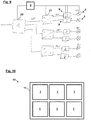
- the lamp 1 can be one of several lamps 1 in a lighting system 10, as shown in Fig. 10 is indicated schematically.
- the lighting system 10 in the example Fig. 10 comprises a luminaire body 11, in which a total of six LED lights 1 are individually used in a 2 x 3 matrix.
- the lamp body 11 can, for example, be made in one piece from a metal material, such as aluminum or an aluminum alloy.
- the lamp body 11 can - as shown schematically in Fig. 10 shown - have a substantially rectangular base area, wherein the individual lights 1 may have an approximately square shape.
- the luminaires 1 can be individually inserted into the luminaire body 11 and removed again, so that the most varied configurations of the luminaire system 10 can be implemented in a flexible manner, depending on the application, with different designs Luminaires 1 are used, which thus function as a kind of light inserts or light modules.
- the luminaire 10 can have a multiplicity of light-emitting diodes (“light emitting diodes”, LEDs) as active illuminants.
- the lamp 1 can therefore also be referred to as an LED lamp 1.
- the LEDs can be, for example, high-voltage LEDs operated with a direct voltage, the operating voltage of which is as close as possible to the effective mains voltage.
- the LEDs can also be low-voltage LEDs.
- Low-voltage LEDs like high-voltage LEDs, are LEDs that are operated with DC voltage, but whose operating voltage is significantly below the mains voltage and which therefore require a separate voltage conversion. However, low-voltage LEDs usually have a somewhat better efficiency than high-voltage LEDs.
- the lighting system 10 can be installed, for example, in a suspended ceiling, for example, or can be attached to a ceiling, and attachment to other parts of a building, for example in the wall area, is also possible.
- the lighting system 10 can thus function as a downlight or wallwasher or the like, for example, one or more of the LED lights 1 being able to produce different emission characteristics, colors or lighting effects, for example.
- the individual LED lights 1 can be freely configured by the customer, for example by a light designer, prior to their manufacture and delivery, for example in order to combine several light effects to be represented by means of LED lights 1 in the desired manner.
- the lighting system 10 thus opens up the possibility of implementing a wide variety of lighting concepts in a flexible manner.
- walls can be lightened at the same time, light can be provided for general lighting and highlights can be set, for example, to illuminate a workplace or to bring out certain furnishings.
- the lamp body 11 and the LED lamps 1 of the lamp system 10 for example different housing shapes, different matrix arrangements, several individual spots in a row or another irregular arrangement of individual spots.
- the system body 11 can be inserted into an installation frame that is not explicitly shown in the figures.
- the mounting frame can be equipped with structures on the circumferential outside thereof which facilitate, for example, "borderless" installation, for example by means of filling.
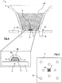
- the exemplary lamp 1 according to 1 to 4 comprises an LED module 2 with a large number of LED lamps 3, which are each designed as individual LEDs and are arranged next to one another in a radiation area 18 in a square basic shape on a circuit board 7, as shown in FIG Fig. 5 is shown.
- Each of the LED lamps 3 can be arranged in (not explicitly shown) lamp receptacles or lamp slots on the circuit board 7, which carries the various LEDs or groups of LEDs and provides a corresponding electrical energy supply for the LED lamps 3.
- the LED lamps 3 can also be fastened on a holder or a receptacle of the LED module 2, which in turn is then fastened on the circuit board 7.
- a board 7 is shown by way of example. It can be seen here that the individual LED lamps 3 are arranged in an alternating pattern, a total of two groups of individual LEDs being provided in this specific example.
- One group includes LEDs that emit in a warm white light, for example at about 2000 K to 3000 K.
- the other group contains cold white LEDs, for example 4500 K to 6000 K.
- the two groups are regulated independently of one another, which means variable color temperature control LED light 1 is made possible with tunable white (English: "Tunable White”) (cf. Fig. 9 further down). Other spectral ranges of the white light color are of course also provided.
- LED lamps 3 can be arranged differently than shown on one or more boards 7, for example in irregular patterns, in several spatially separate groups, etc.
- the LED illuminants 3 are designed in particular as CSP LEDs, which are opaque on the edges in order to avoid cross-light or cross-talk effects, that is to say the mutual influence between adjacent individual LEDs and to avoid to allow strongly bundled and directed broadcasting.
- the CSP technology (“Chip Scale Package”) is characterized by outstanding light output and light intensity out. Due to the more concentrated light beam, adjacent LEDs or groups of LEDs can be placed in close proximity to each other. Overall, this results in an LED module that can be designed to be particularly space-saving. In addition, efficiency losses compared to conventional LED technologies are very limited.
- the LED lamp 1 further comprises a silicone lens 4.
- the silicone lens 4 is arranged directly on the LED module 2 in such a way that the LED lamps 3 are covered by the silicone lens 4 and light emitted by them passes through the silicone lens 4 with as little loss as possible.
- the silicone lens 4 is also double-faceted. Specifically, the silicone lens 4 has a faceted spherically concave light entry surface 5a and a facetted spherically convex light exit surface 5b for homogenizing the light emitted by the LED module 2.
- the silicone lens 4 serves as a sort of mixing chamber for the light from the different LED lamps 3, which, as already mentioned, emit light with two different color temperatures in this example.
- the light is emitted by the LED lamps 3, then enters the silicone lens 4 via the light entry surface 5a and then exits again via the light exit surface 5b.
- Both the light entry surface 5a and the light exit surface 5b have a multiplicity of lens facets 17 which, in combination, bring about a strong mixing of the light beams of the individual LEDs. As a result, highly homogeneous light of a uniform color temperature or color emerges from the silicone lens 4.
- the LED light 1 comprises a faceted reflector 6, which is formed around the silicone lens 4 on the circuit board 7 for reflecting the homogenized light.
- the reflector 6 is illustrated with a square outer shape, a plurality of reflector facets 16 being arranged distributed on inner surfaces of the reflector 6, which form a kind of cone or funnel around the light exit surface 5b of the silicone lens 4.
- the reflector 6 imparts a respective radiation characteristic to the light emitted by the LED lamps 3, for example the radiation characteristic of a downlight of a wall washer, etc.
- the radiation characteristic of the lighting system 10 can thus be adapted depending on the application.
- Some of the LED lights 1 can thus have the radiation characteristic of an individual luminaire which, for example, produces a circular or elliptical cone of light when the lighting system 10 is installed on the ceiling.
- Other LED lights 1 can generate the radiation characteristic of a wall washer, ie have a main emission direction that is oblique to the base of the system body 11. With such a wallwasher characteristic, for example, a wall can be illuminated.
- the circuit board 7 (cf. Fig. 5 ) a plurality of mounting positions 12, at which mounting holes can be provided, for example.
- Fastening means 13 for example locking pins, pressure holders or the like, can in turn be introduced into these fastening bores.
- the silicone lens 4 is applied to a lens base 19, which in turn has a plurality of fastening arms.
- the reflector 6 has a reflector base 14 on a lower side, on which in turn a plurality of locking pins are arranged.
- the silicone lens 4 with the lens base 19 can first be attached to the circuit board.
- the reflector 6 can then be placed on this arrangement and inserted into the circuit board 7.
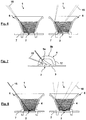
- FIG. 6 schematic sectional views of an exemplary LED light without silicone lens in two different operating states. Links in Fig. 6 three exemplary light beams 15 are shown, which are emitted by the LED module 2. In this case, it is a matter of direct light which emerges directly from the LED light 1 without reflection on the reflector 6. Right in Fig. 6 an operating state is shown in which only indirect light is generated, ie the light rays 15 are first reflected by the LED module 2 on the reflector 6 before they emerge from the LED light 1. For example, how to left in Fig. 6 can recognize, the individual light beams 15 emerge from the LED lamp 1 in a relatively wide range.
- Fig. 7 shows, in contrast, a silicone lens 4, as in the LED lamp 1 Fig. 1 is used.
- the silicone lens 4 is designed with a faceted light entry surface 5a and with a facetted light exit surface 5b for homogenizing the light emitted by the LED module 2.
- the lens facets 17 of both surfaces 5a, 5b act like small aspherical lenses. Each such microlens deflects the light of all LED lamps 3 and thus ultimately acts as a very small light source on the surface of the silicone lens 4, ie a spherical surface.
- Each of these light sources is to a certain extent formed from all LED lamps 3 at the same time and emits their light colors together.
- Fig. 7 shows a few selected light beams 15 as an example.
- Fig. 7 and LED lamps 3 shown in the other figures are assumed to be point sources in a simplified manner, even if each LED lamp 3 in reality emits light from an extended surface, ie each of the light beams 15 shown illuminates a certain surface section, for example on the reflector 6 .
- Fig. 8 shows accordingly Fig. 6 two schematic sectional views of the LED light 1 Fig. 1 in different operating states, one with only direct radiation (left) and one with only indirect radiation (right).
- operating states with a mixture of direct and indirect light naturally also benefit from the advantageous properties of the silicone lens 4.
- Fig. 6 it is clearly visible, for example, on the left how much more the light rays 15 are directed and focused due to the silicone lens 4.
- this leads to the light of differently designed LED illuminants 3, for example LEDs with cold white and warm white light, being mixed and homogenized, so that in total a light with a uniform color or color temperature is emitted.
- the function of the reflector facets 16 here is to first distribute concentrated rays of different colors and fuse them together in order to achieve a final, uniform light distribution.
- Fig. 9 shows a schematic view of a control and supply circuit for the LED light 1 from Fig. 1 .
- the supply of electrical energy is regulated by a control unit 8, which controls the LED lamps 3 in independent control loops / supply loops 9.
- the LED lamps 3 it is possible for the LED lamps 3 to be controlled individually and independently of one another.
- the LED lamps 3 can thus be flexible, individually or in different groups, switchable and / or controllable for generating different lighting effects.
- Fig. 9 shows purely by way of example the pair-wise control of LED lamps 3 and / or groups of LED lamps 3.
- an input rectifier can be designed to direct an AC line voltage into a lamp supply voltage.
- an alternating voltage for example a 230V or 115V AC alternating voltage, can be directed into a lamp supply voltage of 48 volts, which is then further regulated down into smaller suitable supply voltages, for example by a cascaded sequence of switched voltage dividers or voltage converters.
- the rectifier 20 can provide a lamp supply voltage for the LED lamp 1 or the LED lamps 3 located in the LED lamp 1 on the one hand, and a supply voltage for the control unit 8 on the other hand.
- the supply voltage for the control unit 8 can optionally be provided via an additional DC converter for the electronic components of the control unit 8, such as the control signal generator, can be converted into a suitable DC supply voltage.
- the described lighting system 10 is very flexible and easily scalable due to the modular lamp construction with individually usable LED lights 1. In addition, a powerful option is created for generating a wide variety of lighting scenarios with different combinations of radiation characteristics and color temperatures.
- a double-faceted silicone lens 4 and a faceted reflector 6 By combining a double-faceted silicone lens 4 and a faceted reflector 6, a highly homogeneous and directional light radiation is achieved with a minimum system height.
- the lighting system 10 can, for example, in shallow installation depth can be installed in walls or ceilings without special tools, e.g. with a snap and / or locking system.
- the use of CSP LEDs minimizes the loss of efficiency and creates a cost-effective and long-lasting system with high luminous efficacy and light intensity, which can produce different light colors and color temperatures with high uniformity.
Landscapes
- Physics & Mathematics (AREA)
- General Physics & Mathematics (AREA)
- Optics & Photonics (AREA)
- Engineering & Computer Science (AREA)
- General Engineering & Computer Science (AREA)
- Non-Portable Lighting Devices Or Systems Thereof (AREA)
- Securing Globes, Refractors, Reflectors Or The Like (AREA)
Applications Claiming Priority (1)
| Application Number | Priority Date | Filing Date | Title |
|---|---|---|---|
| DE102018217695.7A DE102018217695A1 (de) | 2018-10-16 | 2018-10-16 | LED-Leuchte und Leuchtensystem |
Publications (1)
| Publication Number | Publication Date |
|---|---|
| EP3640529A1 true EP3640529A1 (fr) | 2020-04-22 |
Family
ID=67810391
Family Applications (1)
| Application Number | Title | Priority Date | Filing Date |
|---|---|---|---|
| EP19194289.5A Withdrawn EP3640529A1 (fr) | 2018-10-16 | 2019-08-29 | Luminaire led et système d'éclairage |
Country Status (3)
| Country | Link |
|---|---|
| EP (1) | EP3640529A1 (fr) |
| AT (1) | AT521854B1 (fr) |
| DE (1) | DE102018217695A1 (fr) |
Cited By (1)
| Publication number | Priority date | Publication date | Assignee | Title |
|---|---|---|---|---|
| WO2025012586A1 (fr) * | 2023-07-13 | 2025-01-16 | Gaggione | Dispositif optique comprenant une optique primaire et un dispositif de zoom |
Families Citing this family (1)
| Publication number | Priority date | Publication date | Assignee | Title |
|---|---|---|---|---|
| CN115930156B (zh) * | 2022-12-29 | 2026-07-10 | 苏州欧普照明有限公司 | 复合反射灯罩及照明灯具 |
Citations (11)
| Publication number | Priority date | Publication date | Assignee | Title |
|---|---|---|---|---|
| DE102012007206A1 (de) * | 2012-04-10 | 2013-10-10 | Erco Gmbh | Leuchte |
| WO2014094061A1 (fr) * | 2012-12-21 | 2014-06-26 | Gerard Lighting Pty Ltd | Ensemble optique pour plafonnier intensif à del |
| US20140226337A1 (en) * | 2011-06-17 | 2014-08-14 | Koninklijke Philips N.V. | Led light source |
| KR20150025783A (ko) * | 2013-08-30 | 2015-03-11 | 한국산업기술대학교산학협력단 | 고효율과 고방열 및 광균일도 향상을 위한 led 조명 |
| US9410676B1 (en) * | 2015-03-20 | 2016-08-09 | Green Creative, Llc | LED light bulb |
| DE102015208171A1 (de) * | 2015-05-04 | 2016-11-10 | Osram Gmbh | Bestrahlungsvorrichtung mit Strahlungseinheit |
| US9494297B1 (en) * | 2010-11-19 | 2016-11-15 | Continental Manufacturing, LLC | Solar-powered LED module and lighting fixtures |
| US9574735B2 (en) * | 2010-09-23 | 2017-02-21 | Light Prescriptions Innovators, Llc | Shell integrator |
| US20170059147A1 (en) * | 2015-09-01 | 2017-03-02 | Osram Gmbh | ILLUMINANT WITH LEDs |
| DE102016217332A1 (de) | 2016-09-12 | 2018-03-15 | H4X E.U. | Leuchte |
| US20180160504A1 (en) * | 2015-06-11 | 2018-06-07 | Cree, Inc. | Lighting device including solid state emitters with adjustable control |
Family Cites Families (2)
| Publication number | Priority date | Publication date | Assignee | Title |
|---|---|---|---|---|
| DE102015216111B4 (de) * | 2015-08-24 | 2023-02-16 | Osram Gmbh | Beleuchtungsvorrichtung |
| DE102015011714A1 (de) * | 2015-09-07 | 2017-03-09 | Bartenbach Holding Gmbh | Beleuchtungsvorrichtung |
-
2018
- 2018-10-16 DE DE102018217695.7A patent/DE102018217695A1/de not_active Ceased
- 2018-11-15 AT ATA51007/2018A patent/AT521854B1/de active
-
2019
- 2019-08-29 EP EP19194289.5A patent/EP3640529A1/fr not_active Withdrawn
Patent Citations (12)
| Publication number | Priority date | Publication date | Assignee | Title |
|---|---|---|---|---|
| US9574735B2 (en) * | 2010-09-23 | 2017-02-21 | Light Prescriptions Innovators, Llc | Shell integrator |
| US9494297B1 (en) * | 2010-11-19 | 2016-11-15 | Continental Manufacturing, LLC | Solar-powered LED module and lighting fixtures |
| US20140226337A1 (en) * | 2011-06-17 | 2014-08-14 | Koninklijke Philips N.V. | Led light source |
| DE102012007206A1 (de) * | 2012-04-10 | 2013-10-10 | Erco Gmbh | Leuchte |
| WO2014094061A1 (fr) * | 2012-12-21 | 2014-06-26 | Gerard Lighting Pty Ltd | Ensemble optique pour plafonnier intensif à del |
| KR20150025783A (ko) * | 2013-08-30 | 2015-03-11 | 한국산업기술대학교산학협력단 | 고효율과 고방열 및 광균일도 향상을 위한 led 조명 |
| US9410676B1 (en) * | 2015-03-20 | 2016-08-09 | Green Creative, Llc | LED light bulb |
| US20160327214A1 (en) * | 2015-03-20 | 2016-11-10 | Green Creative Ltd. | Led light bulb |
| DE102015208171A1 (de) * | 2015-05-04 | 2016-11-10 | Osram Gmbh | Bestrahlungsvorrichtung mit Strahlungseinheit |
| US20180160504A1 (en) * | 2015-06-11 | 2018-06-07 | Cree, Inc. | Lighting device including solid state emitters with adjustable control |
| US20170059147A1 (en) * | 2015-09-01 | 2017-03-02 | Osram Gmbh | ILLUMINANT WITH LEDs |
| DE102016217332A1 (de) | 2016-09-12 | 2018-03-15 | H4X E.U. | Leuchte |
Cited By (2)
| Publication number | Priority date | Publication date | Assignee | Title |
|---|---|---|---|---|
| WO2025012586A1 (fr) * | 2023-07-13 | 2025-01-16 | Gaggione | Dispositif optique comprenant une optique primaire et un dispositif de zoom |
| FR3151102A1 (fr) * | 2023-07-13 | 2025-01-17 | Gaggione | Dispositif optique comprenant une optique primaire et un dispositif de zoom |
Also Published As
| Publication number | Publication date |
|---|---|
| DE102018217695A1 (de) | 2020-04-16 |
| AT521854A2 (de) | 2020-05-15 |
| AT521854A3 (de) | 2024-03-15 |
| AT521854B1 (de) | 2024-09-15 |
Similar Documents
| Publication | Publication Date | Title |
|---|---|---|
| EP3293441B1 (fr) | Luminaire | |
| DE102011012130A1 (de) | Beleuchtungsvorrichtung | |
| DE102010062454A1 (de) | Anordnung zur Lichtabgabe | |
| EP2534003B1 (fr) | Lampe de lecture pour véhicules automobiles | |
| DE102009023268A1 (de) | LED-Beleuchtungseinheit mit Reflektor | |
| DE102016120256A1 (de) | Beleuchtungsvorrichtung mit variabler lichtverteilung | |
| DE102008017271B4 (de) | Leuchte mit zwei Lichtquellen in einer Aussparung eines zumindest teilweise lichtleitenden Trägers, Verwendung dieser Leuchte als Hänge-, Wand- oder Standleuchte und Leuchtvorrichtung für eine solche Leuchte | |
| DE102009060607B4 (de) | Rettungszeichenleuchte mit erhöhter Lichtausbeute | |
| AT521854B1 (de) | LED-Leuchte und Leuchtensystem | |
| EP2926324B1 (fr) | Système de cadre lumineux | |
| DE10103781A1 (de) | Einrichtung zur Beleuchtung von Rettungswegen | |
| EP2250433B1 (fr) | Lampe, en particulier à éclairage dirigé vers le bas | |
| DE3318264A1 (de) | Leuchte mit perforiertem hochglanzreflektor | |
| EP2872936A1 (fr) | Injection latérale de lumière | |
| EP1020682A1 (fr) | Lampe de plafond, mural ou à pied pour l'éclairage intérieur | |
| DE202012104303U1 (de) | Leuchte zum Mischen von Licht aus LED- und OLED-Lichtquellen | |
| EP3540299B1 (fr) | Luminaire | |
| EP3869093A1 (fr) | Luminaire à lumière à émission lumineuse directe et indirect | |
| WO2011107479A1 (fr) | Luminaire présentant des éléments de directivité de la lumière | |
| EP3034928B1 (fr) | Éclairage et moyen d'eclairage associe | |
| EP1467141A2 (fr) | Luminaire à surface luminescente fermée | |
| CH710609A1 (de) | Leuchte mit Primär- und Sekundärabstrahlungsrichtung. | |
| EP3627042B1 (fr) | Luminaire pourvu d'un élément de guide de lumière sous la forme de plaque | |
| EP2518388B1 (fr) | Eclairage | |
| DE102004026829B4 (de) | Vorrichtung und Verfahren zum flächigen Abstrahlen von Licht |
Legal Events
| Date | Code | Title | Description |
|---|---|---|---|
| PUAI | Public reference made under article 153(3) epc to a published international application that has entered the european phase |
Free format text: ORIGINAL CODE: 0009012 |
|
| STAA | Information on the status of an ep patent application or granted ep patent |
Free format text: STATUS: THE APPLICATION HAS BEEN PUBLISHED |
|
| AK | Designated contracting states |
Kind code of ref document: A1 Designated state(s): AL AT BE BG CH CY CZ DE DK EE ES FI FR GB GR HR HU IE IS IT LI LT LU LV MC MK MT NL NO PL PT RO RS SE SI SK SM TR |
|
| AX | Request for extension of the european patent |
Extension state: BA ME |
|
| STAA | Information on the status of an ep patent application or granted ep patent |
Free format text: STATUS: REQUEST FOR EXAMINATION WAS MADE |
|
| 17P | Request for examination filed |
Effective date: 20200923 |
|
| RBV | Designated contracting states (corrected) |
Designated state(s): AL AT BE BG CH CY CZ DE DK EE ES FI FR GB GR HR HU IE IS IT LI LT LU LV MC MK MT NL NO PL PT RO RS SE SI SK SM TR |
|
| STAA | Information on the status of an ep patent application or granted ep patent |
Free format text: STATUS: EXAMINATION IS IN PROGRESS |
|
| 17Q | First examination report despatched |
Effective date: 20210503 |
|
| STAA | Information on the status of an ep patent application or granted ep patent |
Free format text: STATUS: THE APPLICATION IS DEEMED TO BE WITHDRAWN |
|
| 18D | Application deemed to be withdrawn |
Effective date: 20240910 |