EP3640538A1 - Stérilisateur à vapeur et son procédé de montage - Google Patents
Stérilisateur à vapeur et son procédé de montage Download PDFInfo
- Publication number
- EP3640538A1 EP3640538A1 EP19203610.1A EP19203610A EP3640538A1 EP 3640538 A1 EP3640538 A1 EP 3640538A1 EP 19203610 A EP19203610 A EP 19203610A EP 3640538 A1 EP3640538 A1 EP 3640538A1
- Authority
- EP
- European Patent Office
- Prior art keywords
- heating element
- section
- heating
- axis
- rotation
- Prior art date
- Legal status (The legal status is an assumption and is not a legal conclusion. Google has not performed a legal analysis and makes no representation as to the accuracy of the status listed.)
- Granted
Links
Images

Classifications
-
- F—MECHANICAL ENGINEERING; LIGHTING; HEATING; WEAPONS; BLASTING
- F22—STEAM GENERATION
- F22B—METHODS OF STEAM GENERATION; STEAM BOILERS
- F22B1/00—Methods of steam generation characterised by form of heating method
- F22B1/28—Methods of steam generation characterised by form of heating method in boilers heated electrically
- F22B1/284—Methods of steam generation characterised by form of heating method in boilers heated electrically with water in reservoirs
Definitions
- the present invention relates to a steam sterilizer according to the preamble of claim 1 and a method for assembling such a steam sterilizer according to the preamble of claim 13.
- a steam sterilizer in which a steam generator with a liquid basin is arranged below a pressure vessel of the steam sterilizer.
- a heater is provided within the liquid pool with which the water in the liquid pool can be heated in order to produce steam.
- a target temperature of 137 ° C. is typically provided for the steam generation. All of the water contained in the liquid pool must be heated to this temperature. At the same time, the heater must always be covered with water, as an exposed heater can lead to overheating.
- the US 2,007,034 A describes a cylindrical steam generator in which two heating elements are arranged vertically.
- the US 2010/0065414 A1 describes an arrangement for heating and distilling water.
- a horizontally arranged heating element which can optionally be designed spirally, is provided in a water basin.
- the present invention has for its object to provide a steam sterilizer that requires less energy in operation than the steam sterilizers known from the prior art, but at the same time can provide the same amount of steam.
- Such a steam sterilizer has a pressure vessel and a steam generator which can be brought into flow connection with the pressure vessel. In this way, steam that is produced in the steam generator can be transferred to the pressure vessel.
- the steam generator has a liquid pool and one arranged in the liquid pool Heating element on.
- the heating element is in particular arranged essentially horizontally in the liquid basin.
- the heating element serves to heat liquid which is kept in stock in the liquid basin in order to generate steam.
- the heating element has a heating section which serves for heat transfer to a liquid which surrounds the heating element. A liquid therefore does not flow through the heating element, but is immersed in a liquid during operation.
- a suitable liquid is water.
- the heating section comprises the entirety of all surfaces of the heating element which are used for heat transfer.
- the heating section thus represents the entirety of all surface areas of the heating element which are used directly for heat transfer to the liquid in the liquid pool.
- the heating element has a connection section with which it can be inserted into the steam generator.
- a thread is formed in the connection section, with the aid of which the heating element can be screwed into a heating element receptacle of the steam generator.
- connection section of the heating element has a (virtual) axis of rotation, around which the heating element can be screwed into the heating element receptacle or unscrewed from the heating element receptacle.
- the heating element is rotated about the axis of rotation in order to insert it into the steam generator or - for example in the case of maintenance and repairs - to remove it from the steam generator.
- the heating section has an underside that extends along the axis of rotation.
- the underside does not necessarily have to extend exactly parallel to the axis of rotation; it can also be slightly inclined to the axis of rotation (up to a maximum of about 20 degrees, in particular 0 degrees to 20 degrees, in particular 3 degrees to 15 degrees, in particular 5 degrees to 10 degrees).
- the heating section has an upper side.
- the top also extends along the axis of rotation.
- the underside also does not necessarily have to be exactly parallel to the axis of rotation. It can also extend slightly inclined to the axis of rotation (up to a maximum of about 20 degrees, in particular 0 degrees to 20 degrees, in particular 3 degrees to 15 degrees, in particular 5 degrees to 10 degrees).
- the angle between the underside of the heating section and the axis of rotation and the angle between the top of the heating section and the axis of rotation can be the same size or different from one another.
- the underside of the heating section is spaced further from the axis of rotation than the top of the heating section. This means that the heating section is not aligned concentrically with the axis of rotation. Rather, it is arranged closer to a bottom of the liquid pool than to a ceiling of the liquid pool.
- this arrangement of the heating section which is eccentric with respect to the axis of rotation makes it possible to arrange the heating element closer to the bottom of the liquid container than is the case with the steam sterilizers known from the prior art. This in turn means that only a smaller volume of liquid is required in order to completely cover the heating element or the heating section with liquid. This means that there is a smaller total volume of liquid that must be heated to the target temperature when generating steam. This is possible with less energy than if a larger amount of liquid had to be heated.
- the acentric arrangement of the heating section with respect to the axis of rotation of the heating element results in energy savings when operating the steam sterilizer.
- the solution to the objective technical problem claimed according to the invention provides for a reduction in the minimum volume V min by using the one used Heating element has a special geometry, in which a longitudinal axis of the heating element runs parallel offset to an axis of rotation about which the heating element is screwed into the steam generator.
- heating elements are typically screwed or screwed into steam generators of steam sterilizers, these heating elements have hitherto generally been designed to be rotationally symmetrical or concentric with an axis of rotation of the heating element. In this way, such a heating element can be screwed into a steam generator particularly easily.
- the solution claimed according to the invention provides a deviation from this rotationally symmetrical or concentric configuration of the heating element known from the prior art. Surprisingly, it has been shown that mounting the heating element is not made significantly more difficult by an eccentric arrangement of the heating section with respect to the axis of rotation of the heating element, since there is typically sufficient installation space in the liquid basins of steam sterilizers for screwing in such a heating element.
- the present invention relates to a steam sterilizer with a pressure vessel and a steam generator, which can be brought into flow connection with the pressure vessel, the steam generator having a liquid basin and a heating element, in particular arranged essentially horizontally in the liquid basin, the heating element being one Heat-dissipating heating section, which comprises in particular the entirety of all surfaces of the heating element used for heat transfer, has a non-heat-dissipating transition section and a connection section serving for connection to the steam generator, a thread being formed in the connection section, with the aid of which the heating element is inserted into a Heating element holder of the steam generator is screwed in.
- connection section has a (virtual) axis of rotation, around which the heating element is moved for screwing into the heating element receptacle or for unscrewing from the heating element receptacle.
- the heating section of the heating element extends along a (virtual) longitudinal axis extending through a central region of the heating section.
- the longitudinal axis of extension and the axis of rotation are not in alignment. Rather, they are offset parallel to one another. This also makes it possible to arrange the heating element closer to a bottom of the liquid container than is the case with the steam sterilizers known from the prior art.
- the parallel offset provided in this aspect of the invention of the longitudinal axis of extension of the heating element to the axis of rotation of the heating element results in energy savings when operating the steam sterilizer.
- the heating element is positioned as deep as possible in the liquid basin of the steam generator, this position experiencing manufacturing limits due to the design of the liquid basin.
- a distance between the axis of rotation and the longitudinal extension axis is between 1 cm and 10 cm, in particular between 2 cm and 9 cm, in particular between 3 cm and 8 cm, in particular between 4 cm and 7 cm, in particular between 5 cm and 6 cm .
- a difference between the distance between the underside and the axis of rotation and the distance between the top and the axis of rotation is between 1 cm and 10 cm, in particular between 2 cm and 9 cm, in particular between 3 cm and 8 cm, in particular between 4 cm and 7 cm, in particular between 5 cm and 6 cm.
- the heating section has a first end and a second end.
- the first end is connected directly or indirectly to the connection section.
- the second end is a free end, that is to say an end that is not connected to any other section of the heating element.
- the free end can be designed in the form of a 180-degree curve of an area of the heating section in order to bring about a change in direction of individual elements of the heating section.
- the heating element has a transition section which is not used for heat emission.
- the transition section is arranged between the connection section and the heating section.
- the transition section is connected to both the heating section and the connection section.
- the transition section runs at an angle both with respect to the axis of rotation and with respect to a longitudinal direction of extension of the top of the heating section.
- Such a transition section makes it particularly easy simply cause a parallel offset of the heating section in relation to the axis of rotation, so that the heating section can be arranged particularly simply eccentrically to the axis of rotation by means of such a transition section.
- the underside of the heating section runs essentially parallel to a bottom of the liquid pool. This simplifies the installation of the heating element and the later operation of the steam sterilizer.
- the bottom of the liquid basin has a slight incline in order to enable the liquid basin to be emptied particularly easily.
- the term “essentially parallel” is to be understood both as an arrangement which emulates such an inclination of the bottom of the liquid basin, and an arrangement in which the heating element runs horizontally, while the bottom of the liquid basin has a slight inclination with respect to the horizontal .
- the top of the heating section can basically run above the axis of rotation. In this case, however, the top of the heating section protrudes less far upward than the axis of rotation than the bottom of the heating section downward from the axis of rotation. In a variant it is provided that in particular the entire top of the heating section extends below the axis of rotation. In this variant, the heating element can be arranged particularly deep in the liquid pool.
- an envelope of the heating section extends along a (virtual) longitudinal axis.
- This axis of longitudinal extension is typically identical to the axis of longitudinal extension which runs through a central region of the heating section.
- the longitudinal extension axis runs through the center of gravity of the cross section of the envelope. It is also provided that the axis of rotation and the longitudinal axis of extension run parallel to one another offset.
- the envelope can also be referred to as a three-dimensional envelope or as a three-dimensional envelope. It describes a virtual three-dimensional figure, which surrounds the entire heating section like a cone jacket or a cylinder jacket and lies with its inside against the outer surface of the heating section.
- the cross section of the envelope typically has a circular or elliptical base area. The center of gravity of such a base area is typically in the center of the base area.
- the longitudinal extension axis in this variant therefore typically runs through the center of the cross section of the envelope.
- the transition section runs between the connection section and the heating section.
- the transition section extends along a transition section axis which runs both at an angle to the axis of rotation and at an angle to the axis of longitudinal extension.
- the transition section axis intersects the rotation axis and the longitudinal extension axis.
- An angle between the transition section axis and the axis of rotation or between the transition section axis and the longitudinal extension axis is in one variant between 5 ° and 30 °, in particular between 10 ° and 25 °, in particular between 15 and 20 °. Since the transition section itself does not serve to give off heat to a liquid that surrounds the heating element, the transition section does not have to be completely covered by liquid. It is only important for the function of the heating element that the heating section of the heating element is completely covered by liquid when the steam sterilizer is operating.
- the longitudinal axis of extension In order for the heating element to be arranged closer to a bottom of the liquid pool, the longitudinal axis of extension must be arranged lower than the axis of rotation. In one embodiment, the longitudinal axis extends exactly below the axis of rotation. Then the heating section of the heating element is typically arranged in its lowest possible position, so that the total volume of the liquid to be heated can be reduced to a minimum in order to still ensure safe operation of the heating element.
- the longitudinal extension axis of the heating element or the underside of the heating section runs essentially parallel to a bottom of the liquid pool.
- a substantially parallel alignment is present when the longitudinal extension axis or the underside of the heating section is inclined to the ground by a maximum of 3 degrees, in particular by a maximum of 0.5 degrees to 2.5 degrees, in particular by a maximum of 1 degree to 2 degrees.
- the heating section of the heating element in this variant runs parallel or inclined up to 3 degrees to the bottom of the liquid pool.
- Such an essentially parallel arrangement of the heating section to the bottom of the liquid pool is preferred, since a substantially uniformly high liquid level in the liquid pool then ensures that the heating section of the heating element is immersed substantially uniformly deep into the liquid in the liquid pool.
- the bottom of the liquid pool runs essentially horizontally.
- the floor then runs essentially horizontally if it is arranged inclined by a maximum of 3 degrees, in particular by a maximum of 0.5 degrees to 2.5 degrees, in particular by a maximum of 1 degree to 2 degrees.
- a maximum of 3 degrees can result in the water in the liquid pool automatically accumulates in an area of the liquid gas pool by providing an emptying nozzle or drain of the liquid pool.
- the longitudinal extension axis of the heating element or the underside of the heating section runs exactly parallel to a bottom of the liquid pool.
- the bottom of the liquid pool runs exactly horizontally.
- the heating element has a positioning element.
- this positioning element ensures automatic positioning of the heating element in the intended installation position, that is to say in particular with a heating section arranged as deep as possible.
- the positioning element abuts against a stop when the heating element is in the desired installation position.
- the positioning element then prevents the heating element from being screwed in further, that is to say a further rotational movement of the heating element in the installation direction.
- the positioning element can be designed, for example, as a limiting pin which abuts a stop when the heating element is in the desired installation position.
- the heating element is locked in its installation position by a locking means, so that it can only be unscrewed from its installation position again after the locking means has been released.
- the positioning element and the locking means can interact with one another and bring about an automatic positioning with subsequent locking of the heating element.
- the heating element is designed as a tubular heater with at least one heating tube.
- a heating tube has a start and an end, which are typically both connected to the connection section of the heating element.
- the heating tube then begins at the connection section in order to assume any geometric configuration and finally ends again at the connection section.
- more than one heating tube is provided. Even then, however, it is usually provided that the heating tubes begin and end at the connection section of the heating element.
- the area in which the heating tube essentially changes its direction of extension by 180 ° represents in one variant a free end of the heating section. Several such 180-degree turns of the heating tube can together form the free end of the heating section.
- the heating tube is shaped such that it has at least 2, in particular at least 3, in particular at least 4, in particular at least 5, in particular has at least 6, in particular at least 7 and very particularly at least 8 sections which run parallel to one another.
- the heating tube can comprise 2 to 10 such parallel sections, in particular 3 to 9, in particular 4 to 8, in particular 5 to 7 such sections. All such sections together or the entire heating tube typically form the heating section if the heating element has only a single heating tube. If the heating element has a plurality of heating tubes, all surfaces of the heating tubes or surfaces of the sections of the heating tubes together form the heating section of the heating element.
- the steam sterilizer has a pressure vessel and a steam generator.
- This steam generator can be brought into flow connection with the pressure vessel.
- the steam generator has a liquid basin and a heating element which is arranged in the liquid basin.
- the heating element has a heating section and a connection section.
- the heating section serves to emit heat to a liquid which surrounds the heating element in the liquid pool.
- the heating section comprises the entirety of all surfaces of the heating element provided for heat transfer, that is to say all those surfaces which directly ensure heat transfer into a liquid which is contained in the liquid pool.
- the connection section is used to connect the heating element to the steam generator. For this purpose, a thread is formed in the connection section.
- the method claimed according to the invention is characterized in that the heating element is screwed into a heating element receptacle of the steam generator for mounting by means of the thread about an axis of rotation of the connection section. This screwing in takes place until the connection section is connected to the heating element receptacle in a fluid-tight manner and an underside of the heating section which extends along the axis of rotation is below the axis of rotation and is further spaced from the axis of rotation than an upper side of the heating section.
- the steam sterilizer has a pressure vessel and a steam generator.
- This steam generator can be brought into flow connection with the pressure vessel.
- the steam generator has a liquid basin and a heating element which is arranged in the liquid basin.
- the heating element has a heating section, one Transitional section and a connecting section.
- the heating section serves to emit heat to a liquid which surrounds the heating element in the liquid pool.
- the heating section includes in particular the entirety of all surfaces of the heating element provided for heat transfer.
- the transition section is not used for heat transfer to such a liquid.
- the connection section is used to connect the heating element to the steam generator. For this purpose, a thread is formed in the connection section.
- the alternative method is characterized in that the heating element is screwed into a heating element receptacle of the steam generator for mounting by means of the thread about an axis of rotation of the connection section. This screwing takes place until the connection section is connected to the heating element receptacle in a fluid-tight manner and at the same time there is a longitudinal axis of extension of the heating element, along which the heating section extends and which runs parallel to the axis of rotation, below the axis of rotation.
- Such an assembly ensures that the heating section of the heating element is arranged lower than the axis of rotation of the heating element and is thus closer to a bottom of the liquid pool than a heating element which is constructed rotationally symmetrically around an axis of rotation.
- the heating element is screwed into the heating element receptacle until the longitudinal extension axis or the underside of the heating section is located exactly below the axis of rotation.
- the heating element is screwed into the heating element receptacle of the steam generator until a positioning element prevents the heating element from being screwed in further.
- this positioning element can be, for example, a stop element which, when screwed in, abuts a stop when the desired or optimal installation position has been reached.
- a locking means can be provided with which the heating element is locked in the desired position after it has been screwed in, in order to avoid an undesired change in position of the heating element.
- the Figure 1A shows a steam sterilizer 1 known from the prior art with a pressure vessel 2 and a steam generator 3 which surrounds the pressure vessel 2 in sections in the form of a jacket.
- a liquid basin 4 of the steam generator 3 is arranged on an underside of the pressure vessel 2, in which water for steam generation is kept in stock.
- a tubular heater 5 is arranged in the liquid pool 4, which is used to heat the water 6 contained in the liquid pool 4.
- V min The minimum liquid level in the liquid pool 4 is indicated by the dashed line labeled V min .
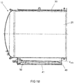
- the Figure 1B shows an embodiment of a steam sterilizer 10.
- This steam sterilizer 10 also has a pressure vessel 20 and a steam generator 30, which surrounds the pressure vessel 20 in sections like a jacket.
- a liquid basin 40 of the steam generator 30 is arranged on an underside of the pressure vessel 20.
- This liquid pool 40 there is a tubular heater 50 which serves as a heating element.
- This tubular heater 50 is used during the operation of the steam sterilizer to evaporate water 60 that is in the liquid basin 4, so that the steam is then shown in a schematic representation in FIG Figure 1B Line, not shown, can be passed from the steam generator 30 into the interior of the pressure vessel 20.
- the tubular heater 50 is stepped along its longitudinal axis; it has a step-like course.
- the tubular heating element 50 can be arranged closer to a lower base 41 of the liquid basin 40 than is the case with the heating elements known from the prior art.
- a lower minimum water volume V min is required in order to be able to operate the tubular heating element 50 safely.
- the total volume of the water to be heated in the liquid pool 40 by the tubular heater 50 is significantly lower than in the steam sterilizers known from the prior art. As a result, less energy is required to heat or partially evaporate this water.
- the steam sterilizer 10 can be operated with a lower energy input than, for example, the steam sterilizer 1, although the amount of steam generated in the steam generator 30 corresponds exactly to the amount that also exists in the steam generator 3 of the steam sterilizer 1 (compare Figure 1A ) can be generated.
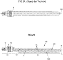
- the Figure 2A shows an enlarged side view of the tubular heater 5 of the Figure 1A .
- This tubular heater 5 has an axis of rotation RA about which it can be rotated in order to be screwed into the steam generator 3 in the region of the liquid pool 4.
- the tubular heater 5 is constructed essentially rotationally symmetrically about the axis of rotation RA.
- the Figure 2B shows an enlarged side view of the tubular heater 50 of the steam sterilizer 10 of FIG Figure 1B .
- This tubular heater 50 also has an axis of rotation R, which runs centrally through a threaded plug 51, which serves as a connection section.
- a thread 52 is provided on this threaded plug 51, with which the tubular heating element 50 can be screwed into a tubular heating element receptacle provided for this purpose in the area of the liquid pool 40 of the steam generator 30.
- a transition section 53 runs obliquely downward from the connecting section 51 and then merges into a straight heating section 54 of the tubular heating element 50.
- This heating section 54 of the tubular heating element 50 extends along a longitudinal axis L, which runs approximately centrally within the heating section 54.
- the heating section 54 has four subsections 55 of a heating tube, which are connected to one another in the manner of a winding and in sections run parallel to one another.
- the heating section comprises all surfaces of the tubular heating element 50 which are provided for heat transfer.
- the transition section 53 extends along a transition section axis U, which intersects both the axis of rotation R and the longitudinal extension axis L at an angle ⁇ , which in the exemplary embodiment of the tubular heating element 50 of FIG Figure 2B is around 15 °.
- the longitudinal extension axis L is offset parallel to the axis of rotation R due to the transition section 53.
- a stepped construction of the tubular heating element 50 is achieved, in which the heating section 54 is no longer aligned with the axis of rotation.
- an underside 540 of the heating section 54 lies lower below the axis of rotation R than an upper side 541 of the heating section 54 lies above the axis of rotation.
- the underside 540 of the heating section 54 is spaced further from the axis of rotation R than the upper side 541 of the heating section 54 Figure 2B the upper side 541 of the heating section 54 is also completely below the axis of rotation R of the tubular heating element 50.
- the heating section 54 it is possible to arrange the heating section 54 further outside a center of the tubular heating element 50 defined by the axis of rotation than is the case with the tubular heating elements known from the prior art. It is thus possible to arrange the heating section 54 overall below the axis of rotation R and thus lower than the heating sections of the tubular heating elements known from the prior art. This means that less water is required to completely cover the heating section 54 when it is arranged in a liquid basin of the same size as a conventional tubular heating element. Less water then also has to be heated in order to generate steam from the water by means of the tubular heating element 50.
- tubular heater shown 50 is another embodiment of a tubular heater for a steam sterilizer.
- the same elements are designated with the same reference numerals as in the previous figures.
- the tubular heater 50 the Figure 2C also has a threaded plug 51 with a thread 52 and a heating section 54 which is on its in the Figure 2C the side shown on the left is connected to the threaded plug 51.
- the heating section 54 comprises all surfaces of the tubular heating element 50, which serve for heat transfer and thus provide heat transfer into a liquid (in particular water) which surrounds the tubular heating element 50 in a liquid basin of a steam sterilizer.
- the tubular heating element 50 again has an axis of rotation R, around which the tubular heating element 50 with its thread 52 can be screwed into a corresponding tubular heating element receptacle.
- An underside 540 of the heating section 54 is spaced further from the axis of rotation R than an upper side 541 of the heating section 54.
- the heating section 54 of the tubular heating element 50 and the rotating axis R of the tubular heating element 50 are not arranged concentrically to one another, but rather eccentrically.
- Such a configuration also results in a lower arrangement of the heating section 54 of the tubular heating element 50, as a result of which the minimum liquid volume that is required for the intended operation of the tubular heating element 50 is smaller than in the solutions known from the prior art.
- the Figure 2C the upper side 541 of the heating section 54 is not continuously below the axis of rotation R. Nevertheless, it is always arranged closer to the axis of rotation R than the lower side 540 of the heating section 54.
- the right side of the heating section 54 is not connected to any other element of the tubular heating element 50, but has a free end 542.
- a heating tube of the heating element makes a 180-degree curve in order to change the direction of the course of the heating tube.
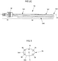
- FIG. 3 shows a schematic cross-sectional view through the tubular heater 50 of FIG Figure 2B or the Figure 2C in the area of the heating section 54 of the respective tubular heating element 50.
- the subsections 55 of the heating tube of the tubular heating element 50 can be clearly seen.
- the entire heating tube with its subsections 55 provides the entire surfaces of the heating section 54 provided for heat transfer.
- a (virtual) envelope 543 is placed around the heating section 54.
- the envelope 543 has the shape of a cylinder jacket (it is open at the free end 542 of the heating section 54; compare this to that Figure 2C ) and runs on an outside of the surface of the heating portion 54.
- the envelope 543 includes an elliptical base 544 in its interior.
- the center of gravity of this base area 544 lies in the center of the base area 544.
- a longitudinal extension axis L of the heating section 54 runs through this center of gravity.
- the tubular heating element 50 In the installed state of the tubular heating element 50, it is arranged lower than the axis of rotation R of the tubular heating element 50. This results in an acentric alignment of the heating section 54 or the longitudinal extension axis L of the heating section 54 with respect to the axis of rotation R. Consequently, it is possible to arrange the heating pipe with its subsections 55 deeper in the liquid basin of a steam sterilizer than in the case of the prior art known solutions is the case.
Landscapes
- Engineering & Computer Science (AREA)
- Life Sciences & Earth Sciences (AREA)
- Sustainable Development (AREA)
- Sustainable Energy (AREA)
- Physics & Mathematics (AREA)
- Thermal Sciences (AREA)
- Mechanical Engineering (AREA)
- General Engineering & Computer Science (AREA)
- Apparatus For Disinfection Or Sterilisation (AREA)
Applications Claiming Priority (1)
| Application Number | Priority Date | Filing Date | Title |
|---|---|---|---|
| EP18201284 | 2018-10-18 |
Publications (2)
| Publication Number | Publication Date |
|---|---|
| EP3640538A1 true EP3640538A1 (fr) | 2020-04-22 |
| EP3640538B1 EP3640538B1 (fr) | 2021-08-11 |
Family
ID=63914904
Family Applications (1)
| Application Number | Title | Priority Date | Filing Date |
|---|---|---|---|
| EP19203610.1A Active EP3640538B1 (fr) | 2018-10-18 | 2019-10-16 | Stérilisateur à vapeur et son procédé de montage |
Country Status (1)
| Country | Link |
|---|---|
| EP (1) | EP3640538B1 (fr) |
Citations (8)
| Publication number | Priority date | Publication date | Assignee | Title |
|---|---|---|---|---|
| US1874244A (en) * | 1928-08-16 | 1932-08-30 | Sydney N Coates | Electric steam boiler |
| US2007034A (en) | 1930-07-07 | 1935-07-02 | Linus H Jones | Steam boiler of the flash type |
| US2494654A (en) * | 1948-09-07 | 1950-01-17 | Super Mold Corp | Boiler |
| CH281242A (fr) * | 1945-06-13 | 1952-02-29 | Steam Torch Corp | Procédé de surchauffe de vapeur, et dispositif générateur de vapeur surchauffée pour la mise en oeuvre de ce procédé. |
| GB1090313A (en) * | 1965-04-12 | 1967-11-08 | John Mortimer Cronin | Improvements relating to apparatus for stripping and cleaning wall coverings |
| FR2201747A5 (fr) * | 1972-10-03 | 1974-04-26 | Setric | |
| DE10260895A1 (de) | 2002-12-17 | 2004-07-08 | Melag Ohg | Interne Dampfversorgung für Dampfsterilisatoren |
| US20100065414A1 (en) | 2006-06-26 | 2010-03-18 | Willem Luloff Rautenbach | Water heating and distillation arrangement |
-
2019
- 2019-10-16 EP EP19203610.1A patent/EP3640538B1/fr active Active
Patent Citations (8)
| Publication number | Priority date | Publication date | Assignee | Title |
|---|---|---|---|---|
| US1874244A (en) * | 1928-08-16 | 1932-08-30 | Sydney N Coates | Electric steam boiler |
| US2007034A (en) | 1930-07-07 | 1935-07-02 | Linus H Jones | Steam boiler of the flash type |
| CH281242A (fr) * | 1945-06-13 | 1952-02-29 | Steam Torch Corp | Procédé de surchauffe de vapeur, et dispositif générateur de vapeur surchauffée pour la mise en oeuvre de ce procédé. |
| US2494654A (en) * | 1948-09-07 | 1950-01-17 | Super Mold Corp | Boiler |
| GB1090313A (en) * | 1965-04-12 | 1967-11-08 | John Mortimer Cronin | Improvements relating to apparatus for stripping and cleaning wall coverings |
| FR2201747A5 (fr) * | 1972-10-03 | 1974-04-26 | Setric | |
| DE10260895A1 (de) | 2002-12-17 | 2004-07-08 | Melag Ohg | Interne Dampfversorgung für Dampfsterilisatoren |
| US20100065414A1 (en) | 2006-06-26 | 2010-03-18 | Willem Luloff Rautenbach | Water heating and distillation arrangement |
Also Published As
| Publication number | Publication date |
|---|---|
| EP3640538B1 (fr) | 2021-08-11 |
Similar Documents
| Publication | Publication Date | Title |
|---|---|---|
| EP2271375A1 (fr) | Appareil et procédé pour désinfecter, stériliser et/ou entretenir des instruments médicaux, notamment dentaires | |
| DE112015003259T5 (de) | Wärmepumpe und Geschirrspülmaschine mit einer solchen Wärmepumpe | |
| DE8218000U1 (de) | Vorrichtung zum waschen von gemuese, fruechten oder aehnlichen produkten | |
| DE3435155A1 (de) | Selbstausrichtende verbindungsvorrichtung | |
| DE3625862A1 (de) | Verfahren und vorrichtung zur oberflaechenbehandlung fuer waermeaustauscher | |
| DE2735450A1 (de) | Dampferzeuger fuer kernkraftwerke, insbesondere fuer druckwasserreaktoren | |
| EP3081303B1 (fr) | Broyeur a billes a agitateur | |
| DE3221350A1 (de) | Geraet zur bereitstellung hochreinen, sterilen wassers | |
| DE2716180A1 (de) | Thermostatische zelle zur erzeugung einer fluessigkeit mit festgelegter temperatur und festgelegtem reinheitsgrad | |
| DE69112905T2 (de) | Brennstabbündel für Kernreaktor. | |
| EP3640538B1 (fr) | Stérilisateur à vapeur et son procédé de montage | |
| WO2020254169A1 (fr) | Dispositif et procédé destinés à désinfecter un fluide au moyen de lumière uv | |
| DE2734981C2 (de) | Sperrmuttervorrichtung | |
| DE3532261C2 (fr) | ||
| EP0173038B1 (fr) | Soupape de surpression pour une chaudière d'étuve pour traiter les aliments à la vapeur | |
| EP1464388A1 (fr) | Traitement par micro-ondes de substances chemiques dans un récient | |
| DE102004025302B3 (de) | Behälter und Verfahren zur gasdichten Kapselung eines radioaktiven Gegenstandes | |
| CH634944A5 (de) | Vorrichtung zum verschluss von rohroeffnungen und zur loesbaren befestigung von laengsbelasteten bauteilen in den rohren. | |
| DE3214064C2 (fr) | ||
| CH653372A5 (de) | Verdampfertiegel fuer vakuum-aufdampfanlagen. | |
| DE2534757C3 (de) | Einrichtung zur elektrischen Behandlung von Flüssigkeiten, die Mikroorganismen enthalten | |
| DE68915883T2 (de) | Behälterverschluss. | |
| EP3638394B1 (fr) | Appareil de laboratoire destiné à l'évaporation d'une substance | |
| CH659881A5 (de) | Vorrichtung zur verteilung der absorptionsfluessigkeit in einem absorptionskuehlapparat. | |
| DE3134804A1 (de) | Dampfablass- und ueberdruckventil |
Legal Events
| Date | Code | Title | Description |
|---|---|---|---|
| PUAI | Public reference made under article 153(3) epc to a published international application that has entered the european phase |
Free format text: ORIGINAL CODE: 0009012 |
|
| STAA | Information on the status of an ep patent application or granted ep patent |
Free format text: STATUS: THE APPLICATION HAS BEEN PUBLISHED |
|
| AK | Designated contracting states |
Kind code of ref document: A1 Designated state(s): AL AT BE BG CH CY CZ DE DK EE ES FI FR GB GR HR HU IE IS IT LI LT LU LV MC MK MT NL NO PL PT RO RS SE SI SK SM TR |
|
| AX | Request for extension of the european patent |
Extension state: BA ME |
|
| STAA | Information on the status of an ep patent application or granted ep patent |
Free format text: STATUS: REQUEST FOR EXAMINATION WAS MADE |
|
| 17P | Request for examination filed |
Effective date: 20200525 |
|
| RBV | Designated contracting states (corrected) |
Designated state(s): AL AT BE BG CH CY CZ DE DK EE ES FI FR GB GR HR HU IE IS IT LI LT LU LV MC MK MT NL NO PL PT RO RS SE SI SK SM TR |
|
| GRAP | Despatch of communication of intention to grant a patent |
Free format text: ORIGINAL CODE: EPIDOSNIGR1 |
|
| STAA | Information on the status of an ep patent application or granted ep patent |
Free format text: STATUS: GRANT OF PATENT IS INTENDED |
|
| INTG | Intention to grant announced |
Effective date: 20210303 |
|
| GRAS | Grant fee paid |
Free format text: ORIGINAL CODE: EPIDOSNIGR3 |
|
| GRAA | (expected) grant |
Free format text: ORIGINAL CODE: 0009210 |
|
| STAA | Information on the status of an ep patent application or granted ep patent |
Free format text: STATUS: THE PATENT HAS BEEN GRANTED |
|
| AK | Designated contracting states |
Kind code of ref document: B1 Designated state(s): AL AT BE BG CH CY CZ DE DK EE ES FI FR GB GR HR HU IE IS IT LI LT LU LV MC MK MT NL NO PL PT RO RS SE SI SK SM TR |
|
| REG | Reference to a national code |
Ref country code: CH Ref legal event code: EP |
|
| REG | Reference to a national code |
Ref country code: DE Ref legal event code: R096 Ref document number: 502019002028 Country of ref document: DE |
|
| REG | Reference to a national code |
Ref country code: IE Ref legal event code: FG4D Free format text: LANGUAGE OF EP DOCUMENT: GERMAN Ref country code: AT Ref legal event code: REF Ref document number: 1419742 Country of ref document: AT Kind code of ref document: T Effective date: 20210915 |
|
| REG | Reference to a national code |
Ref country code: LT Ref legal event code: MG9D |
|
| REG | Reference to a national code |
Ref country code: NL Ref legal event code: MP Effective date: 20210811 |
|
| PG25 | Lapsed in a contracting state [announced via postgrant information from national office to epo] |
Ref country code: FI Free format text: LAPSE BECAUSE OF FAILURE TO SUBMIT A TRANSLATION OF THE DESCRIPTION OR TO PAY THE FEE WITHIN THE PRESCRIBED TIME-LIMIT Effective date: 20210811 Ref country code: HR Free format text: LAPSE BECAUSE OF FAILURE TO SUBMIT A TRANSLATION OF THE DESCRIPTION OR TO PAY THE FEE WITHIN THE PRESCRIBED TIME-LIMIT Effective date: 20210811 Ref country code: NO Free format text: LAPSE BECAUSE OF FAILURE TO SUBMIT A TRANSLATION OF THE DESCRIPTION OR TO PAY THE FEE WITHIN THE PRESCRIBED TIME-LIMIT Effective date: 20211111 Ref country code: PT Free format text: LAPSE BECAUSE OF FAILURE TO SUBMIT A TRANSLATION OF THE DESCRIPTION OR TO PAY THE FEE WITHIN THE PRESCRIBED TIME-LIMIT Effective date: 20211213 Ref country code: LT Free format text: LAPSE BECAUSE OF FAILURE TO SUBMIT A TRANSLATION OF THE DESCRIPTION OR TO PAY THE FEE WITHIN THE PRESCRIBED TIME-LIMIT Effective date: 20210811 Ref country code: BG Free format text: LAPSE BECAUSE OF FAILURE TO SUBMIT A TRANSLATION OF THE DESCRIPTION OR TO PAY THE FEE WITHIN THE PRESCRIBED TIME-LIMIT Effective date: 20211111 Ref country code: ES Free format text: LAPSE BECAUSE OF FAILURE TO SUBMIT A TRANSLATION OF THE DESCRIPTION OR TO PAY THE FEE WITHIN THE PRESCRIBED TIME-LIMIT Effective date: 20210811 Ref country code: SE Free format text: LAPSE BECAUSE OF FAILURE TO SUBMIT A TRANSLATION OF THE DESCRIPTION OR TO PAY THE FEE WITHIN THE PRESCRIBED TIME-LIMIT Effective date: 20210811 Ref country code: RS Free format text: LAPSE BECAUSE OF FAILURE TO SUBMIT A TRANSLATION OF THE DESCRIPTION OR TO PAY THE FEE WITHIN THE PRESCRIBED TIME-LIMIT Effective date: 20210811 |
|
| PG25 | Lapsed in a contracting state [announced via postgrant information from national office to epo] |
Ref country code: PL Free format text: LAPSE BECAUSE OF FAILURE TO SUBMIT A TRANSLATION OF THE DESCRIPTION OR TO PAY THE FEE WITHIN THE PRESCRIBED TIME-LIMIT Effective date: 20210811 Ref country code: LV Free format text: LAPSE BECAUSE OF FAILURE TO SUBMIT A TRANSLATION OF THE DESCRIPTION OR TO PAY THE FEE WITHIN THE PRESCRIBED TIME-LIMIT Effective date: 20210811 Ref country code: GR Free format text: LAPSE BECAUSE OF FAILURE TO SUBMIT A TRANSLATION OF THE DESCRIPTION OR TO PAY THE FEE WITHIN THE PRESCRIBED TIME-LIMIT Effective date: 20211112 |
|
| PG25 | Lapsed in a contracting state [announced via postgrant information from national office to epo] |
Ref country code: NL Free format text: LAPSE BECAUSE OF FAILURE TO SUBMIT A TRANSLATION OF THE DESCRIPTION OR TO PAY THE FEE WITHIN THE PRESCRIBED TIME-LIMIT Effective date: 20210811 |
|
| PG25 | Lapsed in a contracting state [announced via postgrant information from national office to epo] |
Ref country code: DK Free format text: LAPSE BECAUSE OF FAILURE TO SUBMIT A TRANSLATION OF THE DESCRIPTION OR TO PAY THE FEE WITHIN THE PRESCRIBED TIME-LIMIT Effective date: 20210811 |
|
| REG | Reference to a national code |
Ref country code: DE Ref legal event code: R097 Ref document number: 502019002028 Country of ref document: DE |
|
| PG25 | Lapsed in a contracting state [announced via postgrant information from national office to epo] |
Ref country code: SM Free format text: LAPSE BECAUSE OF FAILURE TO SUBMIT A TRANSLATION OF THE DESCRIPTION OR TO PAY THE FEE WITHIN THE PRESCRIBED TIME-LIMIT Effective date: 20210811 Ref country code: SK Free format text: LAPSE BECAUSE OF FAILURE TO SUBMIT A TRANSLATION OF THE DESCRIPTION OR TO PAY THE FEE WITHIN THE PRESCRIBED TIME-LIMIT Effective date: 20210811 Ref country code: RO Free format text: LAPSE BECAUSE OF FAILURE TO SUBMIT A TRANSLATION OF THE DESCRIPTION OR TO PAY THE FEE WITHIN THE PRESCRIBED TIME-LIMIT Effective date: 20210811 Ref country code: EE Free format text: LAPSE BECAUSE OF FAILURE TO SUBMIT A TRANSLATION OF THE DESCRIPTION OR TO PAY THE FEE WITHIN THE PRESCRIBED TIME-LIMIT Effective date: 20210811 Ref country code: CZ Free format text: LAPSE BECAUSE OF FAILURE TO SUBMIT A TRANSLATION OF THE DESCRIPTION OR TO PAY THE FEE WITHIN THE PRESCRIBED TIME-LIMIT Effective date: 20210811 Ref country code: AL Free format text: LAPSE BECAUSE OF FAILURE TO SUBMIT A TRANSLATION OF THE DESCRIPTION OR TO PAY THE FEE WITHIN THE PRESCRIBED TIME-LIMIT Effective date: 20210811 |
|
| PLBE | No opposition filed within time limit |
Free format text: ORIGINAL CODE: 0009261 |
|
| STAA | Information on the status of an ep patent application or granted ep patent |
Free format text: STATUS: NO OPPOSITION FILED WITHIN TIME LIMIT |
|
| REG | Reference to a national code |
Ref country code: BE Ref legal event code: MM Effective date: 20211031 |
|
| PG25 | Lapsed in a contracting state [announced via postgrant information from national office to epo] |
Ref country code: MC Free format text: LAPSE BECAUSE OF FAILURE TO SUBMIT A TRANSLATION OF THE DESCRIPTION OR TO PAY THE FEE WITHIN THE PRESCRIBED TIME-LIMIT Effective date: 20210811 |
|
| 26N | No opposition filed |
Effective date: 20220512 |
|
| PG25 | Lapsed in a contracting state [announced via postgrant information from national office to epo] |
Ref country code: LU Free format text: LAPSE BECAUSE OF NON-PAYMENT OF DUE FEES Effective date: 20211016 Ref country code: BE Free format text: LAPSE BECAUSE OF NON-PAYMENT OF DUE FEES Effective date: 20211031 |
|
| PG25 | Lapsed in a contracting state [announced via postgrant information from national office to epo] |
Ref country code: SI Free format text: LAPSE BECAUSE OF FAILURE TO SUBMIT A TRANSLATION OF THE DESCRIPTION OR TO PAY THE FEE WITHIN THE PRESCRIBED TIME-LIMIT Effective date: 20210811 |
|
| PG25 | Lapsed in a contracting state [announced via postgrant information from national office to epo] |
Ref country code: IE Free format text: LAPSE BECAUSE OF NON-PAYMENT OF DUE FEES Effective date: 20211016 |
|
| P01 | Opt-out of the competence of the unified patent court (upc) registered |
Effective date: 20230512 |
|
| PG25 | Lapsed in a contracting state [announced via postgrant information from national office to epo] |
Ref country code: CY Free format text: LAPSE BECAUSE OF FAILURE TO SUBMIT A TRANSLATION OF THE DESCRIPTION OR TO PAY THE FEE WITHIN THE PRESCRIBED TIME-LIMIT Effective date: 20210811 |
|
| PG25 | Lapsed in a contracting state [announced via postgrant information from national office to epo] |
Ref country code: HU Free format text: LAPSE BECAUSE OF FAILURE TO SUBMIT A TRANSLATION OF THE DESCRIPTION OR TO PAY THE FEE WITHIN THE PRESCRIBED TIME-LIMIT; INVALID AB INITIO Effective date: 20191016 |
|
| PG25 | Lapsed in a contracting state [announced via postgrant information from national office to epo] |
Ref country code: MK Free format text: LAPSE BECAUSE OF FAILURE TO SUBMIT A TRANSLATION OF THE DESCRIPTION OR TO PAY THE FEE WITHIN THE PRESCRIBED TIME-LIMIT Effective date: 20210811 |
|
| PG25 | Lapsed in a contracting state [announced via postgrant information from national office to epo] |
Ref country code: MT Free format text: LAPSE BECAUSE OF FAILURE TO SUBMIT A TRANSLATION OF THE DESCRIPTION OR TO PAY THE FEE WITHIN THE PRESCRIBED TIME-LIMIT Effective date: 20210811 |
|
| REG | Reference to a national code |
Ref country code: CH Ref legal event code: U11 Free format text: ST27 STATUS EVENT CODE: U-0-0-U10-U11 (AS PROVIDED BY THE NATIONAL OFFICE) Effective date: 20251101 |
|
| PG25 | Lapsed in a contracting state [announced via postgrant information from national office to epo] |
Ref country code: TR Free format text: LAPSE BECAUSE OF FAILURE TO SUBMIT A TRANSLATION OF THE DESCRIPTION OR TO PAY THE FEE WITHIN THE PRESCRIBED TIME-LIMIT Effective date: 20210811 |
|
| PGFP | Annual fee paid to national office [announced via postgrant information from national office to epo] |
Ref country code: DE Payment date: 20250909 Year of fee payment: 7 |
|
| PGFP | Annual fee paid to national office [announced via postgrant information from national office to epo] |
Ref country code: GB Payment date: 20251024 Year of fee payment: 7 |
|
| PGFP | Annual fee paid to national office [announced via postgrant information from national office to epo] |
Ref country code: AT Payment date: 20251021 Year of fee payment: 7 |
|
| PGFP | Annual fee paid to national office [announced via postgrant information from national office to epo] |
Ref country code: IT Payment date: 20251031 Year of fee payment: 7 |
|
| PGFP | Annual fee paid to national office [announced via postgrant information from national office to epo] |
Ref country code: FR Payment date: 20251027 Year of fee payment: 7 |
|
| PGFP | Annual fee paid to national office [announced via postgrant information from national office to epo] |
Ref country code: CH Payment date: 20251101 Year of fee payment: 7 |