EP3640558B1 - Kommutierende luftauslassluftkanalmaschine und steuerungsverfahren dafür sowie klimatisierungsvorrichtung - Google Patents
Kommutierende luftauslassluftkanalmaschine und steuerungsverfahren dafür sowie klimatisierungsvorrichtung Download PDFInfo
- Publication number
- EP3640558B1 EP3640558B1 EP17913779.9A EP17913779A EP3640558B1 EP 3640558 B1 EP3640558 B1 EP 3640558B1 EP 17913779 A EP17913779 A EP 17913779A EP 3640558 B1 EP3640558 B1 EP 3640558B1
- Authority
- EP
- European Patent Office
- Prior art keywords
- air
- fan
- vent
- serves
- duct machine
- Prior art date
- Legal status (The legal status is an assumption and is not a legal conclusion. Google has not performed a legal analysis and makes no representation as to the accuracy of the status listed.)
- Active
Links
Images

Classifications
-
- F—MECHANICAL ENGINEERING; LIGHTING; HEATING; WEAPONS; BLASTING
- F24—HEATING; RANGES; VENTILATING
- F24F—AIR-CONDITIONING; AIR-HUMIDIFICATION; VENTILATION; USE OF AIR CURRENTS FOR SCREENING
- F24F1/00—Room units for air-conditioning, e.g. separate or self-contained units or units receiving primary air from a central station
- F24F1/0007—Indoor units, e.g. fan coil units
- F24F1/0011—Indoor units, e.g. fan coil units characterised by air outlets
- F24F1/0014—Indoor units, e.g. fan coil units characterised by air outlets having two or more outlet openings
-
- F—MECHANICAL ENGINEERING; LIGHTING; HEATING; WEAPONS; BLASTING
- F24—HEATING; RANGES; VENTILATING
- F24F—AIR-CONDITIONING; AIR-HUMIDIFICATION; VENTILATION; USE OF AIR CURRENTS FOR SCREENING
- F24F1/00—Room units for air-conditioning, e.g. separate or self-contained units or units receiving primary air from a central station
- F24F1/0007—Indoor units, e.g. fan coil units
- F24F1/0018—Indoor units, e.g. fan coil units characterised by fans
- F24F1/0025—Cross-flow or tangential fans
-
- F—MECHANICAL ENGINEERING; LIGHTING; HEATING; WEAPONS; BLASTING
- F24—HEATING; RANGES; VENTILATING
- F24F—AIR-CONDITIONING; AIR-HUMIDIFICATION; VENTILATION; USE OF AIR CURRENTS FOR SCREENING
- F24F1/00—Room units for air-conditioning, e.g. separate or self-contained units or units receiving primary air from a central station
- F24F1/0007—Indoor units, e.g. fan coil units
- F24F1/0018—Indoor units, e.g. fan coil units characterised by fans
- F24F1/0033—Indoor units, e.g. fan coil units characterised by fans having two or more fans
-
- F—MECHANICAL ENGINEERING; LIGHTING; HEATING; WEAPONS; BLASTING
- F24—HEATING; RANGES; VENTILATING
- F24F—AIR-CONDITIONING; AIR-HUMIDIFICATION; VENTILATION; USE OF AIR CURRENTS FOR SCREENING
- F24F11/00—Control or safety arrangements
- F24F11/70—Control systems characterised by their outputs; Constructional details thereof
- F24F11/72—Control systems characterised by their outputs; Constructional details thereof for controlling the supply of treated air, e.g. its pressure
- F24F11/74—Control systems characterised by their outputs; Constructional details thereof for controlling the supply of treated air, e.g. its pressure for controlling air flow rate or air velocity
- F24F11/77—Control systems characterised by their outputs; Constructional details thereof for controlling the supply of treated air, e.g. its pressure for controlling air flow rate or air velocity by controlling the speed of ventilators
-
- F—MECHANICAL ENGINEERING; LIGHTING; HEATING; WEAPONS; BLASTING
- F24—HEATING; RANGES; VENTILATING
- F24F—AIR-CONDITIONING; AIR-HUMIDIFICATION; VENTILATION; USE OF AIR CURRENTS FOR SCREENING
- F24F11/00—Control or safety arrangements
- F24F11/70—Control systems characterised by their outputs; Constructional details thereof
- F24F11/72—Control systems characterised by their outputs; Constructional details thereof for controlling the supply of treated air, e.g. its pressure
- F24F11/79—Control systems characterised by their outputs; Constructional details thereof for controlling the supply of treated air, e.g. its pressure for controlling the direction of the supplied air
-
- F—MECHANICAL ENGINEERING; LIGHTING; HEATING; WEAPONS; BLASTING
- F24—HEATING; RANGES; VENTILATING
- F24F—AIR-CONDITIONING; AIR-HUMIDIFICATION; VENTILATION; USE OF AIR CURRENTS FOR SCREENING
- F24F13/00—Details common to, or for air-conditioning, air-humidification, ventilation or use of air currents for screening
- F24F13/24—Means for preventing or suppressing noise
-
- F—MECHANICAL ENGINEERING; LIGHTING; HEATING; WEAPONS; BLASTING
- F24—HEATING; RANGES; VENTILATING
- F24F—AIR-CONDITIONING; AIR-HUMIDIFICATION; VENTILATION; USE OF AIR CURRENTS FOR SCREENING
- F24F13/00—Details common to, or for air-conditioning, air-humidification, ventilation or use of air currents for screening
- F24F13/24—Means for preventing or suppressing noise
- F24F2013/247—Active noise-suppression
Definitions
- the present application relates to the technical field of air conditioning, in particular to an air duct machine with switchable air-out directions and a control method thereof and an air-conditioning apparatus.
- An air duct machine is short for a duct-type air conditioning equipment, and is a type of central air conditioner. Generally, it connects an indoor unit and an outdoor unit, which are connected through a copper pipe. An air supply pipe is led from indoors and introduced to each room, and air is returned to the indoor unit through an air return pipe, and then cooled and mixed with fresh air to supply fresh air again.
- a cross-flow fan should be respectively arranged at a sideward vent and a downward vent.
- the other fan When one fan rotates as an air supply fan, the other fan is static which is at an air return position, and its motion state has a great influence on return air, thereby impeding entrance of return air and reducing the air return amount, and the contact between return air and blades of a static fan will generate unnecessary noises.
- the air duct type air conditioner comprises a base, first fan blades, second fan blades and an evaporator, wherein all the first fan blades, second fan blades and evaporator are installed inside the base; the evaporator is positioned between the first fan blades and the second fan blades; a first air hole is formed in one side, corresponding to the first fan blades, of the base; a second air hole is formed in one side, corresponding to the second fan blades, of the base; the first air hole comprises a first normally-open passage and a first controllable passage; the second air hole comprises a second normally-open passage and a second controllable passage; the air duct type air conditioner also comprises a first movable worm tongue and a second movable worm tongue, wherein the first movable worm tongue is used for controlling opening and closing of the first controllable passage; the second movable worm tongue is used for controlling opening and closing of
- CN 105276782 A discloses an air flue structure, an indoor unit and an air conditioning plant which are used for outputting air in different directions.
- the air flue structure is used for the indoor unit and comprises at least two air outlets.
- Each air outlet is correspondingly provided with a cross-flow fan structure.
- the air outflow directions of the air outlets form included angles.
- WO 2007/136202 A1 discloses an air conditioner includes a case provided with openings, a heat exchanger disposed in the case, one or more fans disposed in the case, and a variation unit that is movably disposed around the fans to vary air inlet and outlet directions.
- a technical problem to be solved in the present application is to provide an air duct machine with switchable air-out directions and a control method thereof and an air-conditioning apparatus, so as to increase the air output amount and lower the noise.
- an air duct machine with switchable air-out directions including a housing, a first fan, a second fan and a control mechanism, wherein the first fan and the second fan are both mounted in the housing, the housing has a first vent and a second vent, the first vent is disposed on the side of the first fan, the second vent is disposed on the side of the second fan, and a communicating air channel is formed between the first vent and the second vent;
- first fan and the second fan are both cross-flow fans.
- first fan and the second fan are configured to rotate in the same direction.
- the present application further correspondingly provides a control method of an air duct machine with switchable air-out directions, including:
- the present application further provides an air-conditioning apparatus which includes the above air duct machine with switchable air-out directions.
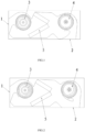
- an air duct machine with switchable air-out directions includes a housing, a first fan 3, a second fan 4, a heat exchanger 5 and a control mechanism (not shown in the figures), wherein the first fan 3 and the second fan 4 are both mounted in the housing, the housing is formed with a first vent 1 at a side corresponding to the first fan 3, the housing is formed with a second vent 2 at a side corresponding to the second fan 4, specifically or preferably, the first vent 1 is located at the lateral side of the housing, and the second vent 2 is located at the bottom the housing.
- a communicating air channel is formed between the first vent 1 and the second vent 2, the heat exchanger 5 is arranged in a middle region of the air channel, and is located between the first fan 3 and the second fan 4.
- an air duct machine with switchable air-out directions of the present application utilizes a control mechanism to achieve linkage control of a first fan 3 and a second fan 4.
- a control mechanism controls the first fan 3 which serves as an air-out fan to supply air to the first vent 1, wherein the first fan 3 rotates in an anti-clockwise direction
- the control mechanism controls the second fan 4 which serves as a regulating fan to rotate towards a direction opposite to a direction in which air is supplied to the second vent 2, wherein the second fan 4 rotates in an anti-clockwise direction, and the second vent 2 which serves as a return vent returns air to the air channel; and the reverse rotation of the second fan 4 reduces obstruction to return air, optimizes a flow field of return air, enlarges the area of return air, increases the air output amount, and effectively lowers the noise.
- the control mechanism controls the second fan 4 which serves as an air-out fan to supply air to the second vent 2, wherein the second fan 4 rotates in a clockwise direction, and the control mechanism controls the first fan 3 which serves as a regulating fan to rotate in a direction opposite to a direction in which air is supplied to the first vent 1, wherein the first fan 3 rotates in an anti-clockwise direction, and the first vent 1 which serves as a return vent returns air to the air channel; and the reverse rotation of the first fan 3 reduces obstruction to return air, optimizes a flow field of return air, enlarges the area of return air, increases the air output amount, and effectively lowers the noise.
- a regulating fan rotates in a direction opposite to a direction in which air is supplied to a corresponding vent, such that the regulating fan exerts no negative effect on a flow field in a whole air channel, and further has a positive effect on the air channel flow field to some extent, so as to increase the air output amount and lower the noise.
- the first fan 3 and the second fan 4 are both particularly cross-flow fans.
- the fans in the air duct machine with switchable air-out directions of the present application are cross-flow fans, the effects of increasing the air output amount and lowering the noise are especially dramatic.
- the first fan 3 and the second fan 4 rotate in the same direction, in this way, during design, they can be driven by a same motor, thereby facilitating control.
- the rotational directions of the first fan 3 and the second fan 4 can also be opposite, which depends on design of blades of the fans and position selection of vents.
- Table 1 Sideward air outlet of a first vent 1 Downward air outlet of a second vent 2 Rotational speed (rpm) of a blade of a first fan 3 Air output amount (m 3 /min) Rotational speed (rpm) of a blade of a second fan 4 Air output amount (m 3 /min) 350 189 350 203 500 221 500 298 650 330 650 374 800 433 800 484 950 531 950 582 1100 623 1100 661 1250 718 1250 748 1400 822 1400 845
- the range of a rotational speed W1 of an air-out fan is 400r/min-1400r/min.
- a regulating fan exerts no negative effect on a flow field in the whole air channel, and further has a positive effect on the air channel flow field to some extent, and the effects of increasing the air output amount and lowering the noise of an air duct machine with switchable air-out directions are especially dramatic.
- a first fan 3 is an air-out fan, and a second fan 4 is a regulating fan
- a first fan 3 is an air-out fan
- a second fan 4 is a regulating fan
- Table 2 Rotational speed (rpm) of a blade of a first fan 3
- Rotational speed (rpm) of a fan of a second fan 4 Air amount (m 3 /min) 650 0 330 650 270 352 650 300 390 650 330 348 950 0 531 950 390 550 950 415 630 950 440 566 1250 0 718 1250 470 745 1250 510 860 1250 540 760
- the present application correspondingly provides a control method of the abovementioned air duct machine with switchable air-out directions, including:
- a control method of an air duct machine with switchable air-out directions of the present application achieves linkage control of a first fan 3 and a second fan 4.
- the first fan 3 which serves as an air-out fan is caused to supply air to the first vent 1, wherein the first fan 3 rotates in an anti-clockwise direction
- the second fan 4 which serves as a regulating fan is caused to rotate towards a direction opposite to a direction in which air is supplied to the second vent 2, wherein the second fan 4 rotates in an anti-clockwise direction, and the second vent 2 which serves as a return vent returns air to an air channel; and the reverse rotation of the second fan 4 reduces obstruction to return air, optimizes a flow field of return air, enlarges the area of return air, increases the air output amount, and effectively lowers the noise.
- the second fan 4 which serves as an air-out fan is caused to supply air to the second vent 2, wherein the second fan 4 rotates in a clockwise direction, and the first fan 3 which serves as a regulating fan is caused to rotate in a direction opposite to a direction in which air is supplied to the first vent 1, wherein the first fan 3 rotates in an anti-clockwise direction, the first vent 1 which serves as a return vent returns air to the air channel; and the reverse rotation of the first fan 3 reduces obstruction to return air, optimizes a flow field of return air, enlarges the area of return air, increases the air output amount, and effectively lowers the noise.
- the range of a rotational speed W1 of the air-out fan is 400r/min-1400r/min, such that an air duct machine with switchable air-out directions can maximize its performance.
- a regulating fan exerts no negative effect on a flow field in the whole air channel, and further has a positive effect on the air channel flow field to some extent, and the effects of increasing the air output amount and lowering the noise of an air duct machine with switchable air-out directions are especially dramatic.
- the present application further provides an air-conditioning apparatus which includes the abovementioned air duct machine with switchable air-out directions. Since the air duct machine with switchable air-out directions of the present application can increase the air output amount and lower the noise, correspondingly, the air-conditioning apparatus of the present application also has the above beneficial technical effects, which will not be repeated herein.
Landscapes
- Engineering & Computer Science (AREA)
- Chemical & Material Sciences (AREA)
- Combustion & Propulsion (AREA)
- Mechanical Engineering (AREA)
- General Engineering & Computer Science (AREA)
- Physics & Mathematics (AREA)
- Fluid Mechanics (AREA)
- Air Conditioning Control Device (AREA)
- Structures Of Non-Positive Displacement Pumps (AREA)
- Air-Conditioning For Vehicles (AREA)
- Control Of Positive-Displacement Air Blowers (AREA)
Claims (5)
- Luftkanalmaschine mit schaltbaren Ausblasrichtungen, umfassend ein Gehäuse, einen ersten Lüfter (3), einen zweiten Lüfter (4) und einen Steuermechanismus, wobei der erste Lüfter (3) und der zweite Lüfter (4) beide in dem Gehäuse montiert sind, das Gehäuse eine erste Entlüftung (1) und eine zweite Entlüftung (2) aufweist, die erste Entlüftung (1) auf der Seite des ersten Lüfters (3) angeordnet ist und die zweite Entlüftung (2) auf der Seite des zweiten Lüfters (4) angeordnet ist und ein Verbindungsluftkanal zwischen der ersten Entlüftung (1) und der zweiten Entlüftung (2) gebildet ist,wobei sich die erste Entlüftung (1) an der seitlichen Seite des Gehäuses befindet und sich die zweite Entlüftung (2) an der Unterseite des Gehäuses befindet,der erste Lüfter (3) in einem Luftauslasszustand der ersten Entlüftung (1) als Luftauslasslüfter dient und der zweite Lüfter (4) als Regulierungslüfter dient, und der Steuermechanismus konfiguriert ist, um den ersten Lüfter (3) zu steuern, um der ersten Entlüftung (1) Luft zuzuführen, und der zweite Lüfter (4) zu steuern, um in einer Richtung entgegengesetzt zu einer Richtung zu drehen, in der der zweiten Entlüftung (2) Luft zugeführt wird; undder zweite Lüfter (4) in einem Entlüftungszustand der zweiten Entlüftung (2) als Luftauslasslüfter dient und der erste Lüfter (3) als Regulierungslüfter dient, der Steuermechanismus konfiguriert ist, um den zweiten Lüfter (4) zu steuern, um der zweiten Entlüftung (2) Luft zuzuführen, und den ersten Lüfter (3) zu steuern, um in einer Richtung entgegengesetzt zu einer Richtung zu drehen, in der der ersten Entlüftung (1) Luft zugeführt wird,dadurch gekennzeichnet, dass eine Drehzahl W2 des Regulierungslüfters und die Drehzahl W1 des Luftauslasslüfters die folgende Beziehung erfüllen:
 wobei 60 U/min ≤ A ≤ 120 U/min, und wobei der Bereich einer Drehzahl W1 des Luftauslasslüfters 400 U/min-1400 U/min ist.
 - Luftkanalmaschine mit schaltbaren Ausblasrichtungen nach Anspruch 1, wobei der erste Lüfter (3) und der zweite Lüfter (4) beide Querstromlüfter sind.
- Luftkanalmaschine mit schaltbaren Ausblasrichtungen nach Anspruch 1, wobei der erste Lüfter (3) und der zweite Lüfter (4) konfiguriert sind, in derselben Richtung zu drehen.
- Steuerungsverfahren einer Luftkanalmaschine mit schaltbaren Ausblasrichtungen nach Anspruch 1, umfassend:in einem Entlüftungszustand der ersten Entlüftung (1), Veranlassen, dass der erste Lüfter (3), der als Luftauslasslüfter dient, in einer Richtung dreht, in der der ersten Entlüftung (1) Luft zugeführt wird, und Veranlassen, dass der zweite Lüfter (4), der als Regulierungslüfter dient, in einer Richtung entgegengesetzt einer Richtung dreht, in der der zweiten Entlüftung (2) Luft zugeführt wird;in einem Entlüftungszustand der zweiten Entlüftung (2), Veranlassen, dass der zweite Lüfter (4), der als Luftauslasslüfter dient, in einer Richtung dreht, in der der zweiten Entlüftung (2) Luft zugeführt wird, und Veranlassen, dass der erste Lüfter (3), der als Regulierungslüfter dient, in einer Richtung entgegengesetzt einer Richtung dreht, in der der ersten Entlüftung (1) Luft zugeführt wird, dadurch gekennzeichnet, dass eine Drehzahl W2 des Regulierungslüfters und die Drehzahl W1 des Luftauslasslüfters die folgende Beziehung erfüllen:
 wobei 60 U/min ≤ A ≤ 120 U/min, und wobei der Bereich einer Drehzahl W1 des Luftauslasslüfters 400 U/min-1400 U/min ist.
 - Klimagerät, umfassend die Luftkanalmaschine mit schaltbaren Ausblasrichtungen nach einem der Ansprüche 1 bis 4.
Applications Claiming Priority (2)
| Application Number | Priority Date | Filing Date | Title |
|---|---|---|---|
| CN201710445762.6A CN107084440A (zh) | 2017-06-14 | 2017-06-14 | 可换向出风风管机及其控制方法以及空调装置 |
| PCT/CN2017/118317 WO2018227924A1 (zh) | 2017-06-14 | 2017-12-25 | 可换向出风风管机及其控制方法以及空调装置 |
Publications (3)
| Publication Number | Publication Date |
|---|---|
| EP3640558A1 EP3640558A1 (de) | 2020-04-22 |
| EP3640558A4 EP3640558A4 (de) | 2021-02-24 |
| EP3640558B1 true EP3640558B1 (de) | 2025-06-04 |
Family
ID=59606927
Family Applications (1)
| Application Number | Title | Priority Date | Filing Date |
|---|---|---|---|
| EP17913779.9A Active EP3640558B1 (de) | 2017-06-14 | 2017-12-25 | Kommutierende luftauslassluftkanalmaschine und steuerungsverfahren dafür sowie klimatisierungsvorrichtung |
Country Status (4)
| Country | Link |
|---|---|
| US (1) | US11384952B2 (de) |
| EP (1) | EP3640558B1 (de) |
| CN (1) | CN107084440A (de) |
| WO (1) | WO2018227924A1 (de) |
Families Citing this family (9)
| Publication number | Priority date | Publication date | Assignee | Title |
|---|---|---|---|---|
| CN107084440A (zh) * | 2017-06-14 | 2017-08-22 | 珠海格力电器股份有限公司 | 可换向出风风管机及其控制方法以及空调装置 |
| CN110906494A (zh) * | 2018-09-17 | 2020-03-24 | 青岛海尔空调器有限总公司 | 空调新风机换气控制方法 |
| CN109114675B (zh) * | 2018-11-05 | 2024-05-14 | 珠海格力电器股份有限公司 | 空调设备及风管机 |
| CN110425637B (zh) * | 2019-08-05 | 2024-06-25 | 宁波奥克斯电气股份有限公司 | 一种可实现多种出风模式的室内机及其控制方法 |
| CN113217994A (zh) * | 2021-05-10 | 2021-08-06 | 海信(山东)空调有限公司 | 双风道空调的出风控制方法和室内机 |
| CN113465027B (zh) * | 2021-06-17 | 2023-05-26 | 青岛海尔空调电子有限公司 | 可逆风管机及其出风控制方法 |
| CN116164341A (zh) * | 2021-11-25 | 2023-05-26 | 东芝开利空调(中国)有限公司 | 空调装置的室内单元 |
| CN114738831B (zh) * | 2022-03-17 | 2024-07-09 | 青岛海尔空调电子有限公司 | 用于控制空调的方法、装置、空调和存储介质 |
| CN115823720A (zh) * | 2022-11-16 | 2023-03-21 | 青岛海尔空调器有限总公司 | 一种空调器的控制方法及空调器 |
Family Cites Families (14)
| Publication number | Priority date | Publication date | Assignee | Title |
|---|---|---|---|---|
| JPH11201490A (ja) * | 1998-01-20 | 1999-07-30 | Fujitsu General Ltd | 空気調和機 |
| JP2001165495A (ja) * | 1999-12-09 | 2001-06-22 | Ryuki Engineering:Kk | 換気用風管装置 |
| KR100644544B1 (ko) | 2005-10-28 | 2006-11-10 | 엘지전자 주식회사 | 공기조화기 |
| KR100809784B1 (ko) | 2006-05-20 | 2008-03-04 | 엘지전자 주식회사 | 횡류팬을 포함하는 공기 조화기 |
| CN202560599U (zh) * | 2012-04-10 | 2012-11-28 | 广东美的制冷设备有限公司 | 一种串联风机系统 |
| CN103673076B (zh) * | 2012-09-10 | 2016-08-24 | 珠海格力电器股份有限公司 | 立式空调器 |
| CN103776090A (zh) | 2012-10-18 | 2014-05-07 | 珠海格力电器股份有限公司 | 房间空调器及其控制方法 |
| WO2015106385A1 (zh) * | 2014-01-14 | 2015-07-23 | 中山大洋电机股份有限公司 | 一种应用在hvac系统中的ecm电机的恒风量控制方法 |
| CN204285717U (zh) * | 2014-10-20 | 2015-04-22 | 重庆绿彰科技发展有限公司 | 幕墙动力通风器 |
| CN105276782A (zh) | 2015-10-12 | 2016-01-27 | 珠海格力电器股份有限公司 | 风道结构、室内机及空气调节装置 |
| CN205065934U (zh) * | 2015-10-12 | 2016-03-02 | 珠海格力电器股份有限公司 | 风管机 |
| CN106440030A (zh) * | 2016-09-26 | 2017-02-22 | 珠海格力电器股份有限公司 | 风管机和空调装置 |
| CN107084440A (zh) | 2017-06-14 | 2017-08-22 | 珠海格力电器股份有限公司 | 可换向出风风管机及其控制方法以及空调装置 |
| CN206817628U (zh) * | 2017-06-14 | 2017-12-29 | 珠海格力电器股份有限公司 | 可换向出风风管机以及空调装置 |
-
2017
- 2017-06-14 CN CN201710445762.6A patent/CN107084440A/zh active Pending
- 2017-12-25 WO PCT/CN2017/118317 patent/WO2018227924A1/zh not_active Ceased
- 2017-12-25 EP EP17913779.9A patent/EP3640558B1/de active Active
- 2017-12-25 US US16/607,268 patent/US11384952B2/en active Active
Also Published As
| Publication number | Publication date |
|---|---|
| US11384952B2 (en) | 2022-07-12 |
| US20200300496A1 (en) | 2020-09-24 |
| WO2018227924A1 (zh) | 2018-12-20 |
| EP3640558A4 (de) | 2021-02-24 |
| EP3640558A1 (de) | 2020-04-22 |
| CN107084440A (zh) | 2017-08-22 |
Similar Documents
| Publication | Publication Date | Title |
|---|---|---|
| EP3640558B1 (de) | Kommutierende luftauslassluftkanalmaschine und steuerungsverfahren dafür sowie klimatisierungsvorrichtung | |
| EP0091643A2 (de) | Klimagerät | |
| US3394755A (en) | Air screen creating-air conditioning apparatus | |
| CN107238131B (zh) | 一种空调室内机及空调 | |
| CN213983780U (zh) | 一种新风空调室内机及新风空调器 | |
| CN113959009B (zh) | 壁挂式空调室内机和空调器 | |
| SE542661C2 (en) | AIR TERMINAL DEVICE FOR CONTROL OF AIR FLOW IN A VENTILATION SYSTEM | |
| CN211345513U (zh) | 空调室内机及其风道组件 | |
| EP1316760B1 (de) | Zierplatte für klimaanlage, abblaseinheit für luftauslass und klimaanlage | |
| KR20030057926A (ko) | 공기조화기의 풍향조절장치 | |
| JP2010243081A (ja) | 空気調和機の室内機 | |
| CN213514112U (zh) | 空调柜机 | |
| CN213119472U (zh) | 一种空调出风口的遮蔽面板 | |
| JPH08152187A (ja) | 空気調和機 | |
| JP2008151477A (ja) | 床置型空気調和機 | |
| CN109798594B (zh) | 送风结构及具有其的空调室内机 | |
| CN111811053A (zh) | 空调室内机以及空调控制方法 | |
| CN219160587U (zh) | 一种风道中调节风向的机构 | |
| CN107401775B (zh) | 内导风板及具有其的壁挂式空调室内机 | |
| KR102451313B1 (ko) | 공기조화기 | |
| CN206817628U (zh) | 可换向出风风管机以及空调装置 | |
| CN220852340U (zh) | 一种立式空调室内机 | |
| CN115388531B (zh) | 空调室内机、空调及空调室内机的控制方法 | |
| CN218154499U (zh) | 空调器室内机 | |
| CN217441807U (zh) | 空调器室内机 |
Legal Events
| Date | Code | Title | Description |
|---|---|---|---|
| STAA | Information on the status of an ep patent application or granted ep patent |
Free format text: STATUS: THE INTERNATIONAL PUBLICATION HAS BEEN MADE |
|
| PUAI | Public reference made under article 153(3) epc to a published international application that has entered the european phase |
Free format text: ORIGINAL CODE: 0009012 |
|
| STAA | Information on the status of an ep patent application or granted ep patent |
Free format text: STATUS: REQUEST FOR EXAMINATION WAS MADE |
|
| 17P | Request for examination filed |
Effective date: 20191010 |
|
| AK | Designated contracting states |
Kind code of ref document: A1 Designated state(s): AL AT BE BG CH CY CZ DE DK EE ES FI FR GB GR HR HU IE IS IT LI LT LU LV MC MK MT NL NO PL PT RO RS SE SI SK SM TR |
|
| AX | Request for extension of the european patent |
Extension state: BA ME |
|
| DAV | Request for validation of the european patent (deleted) | ||
| DAX | Request for extension of the european patent (deleted) | ||
| REG | Reference to a national code |
Ref country code: DE Ref legal event code: R079 Free format text: PREVIOUS MAIN CLASS: F24F0013000000 Ipc: F24F0001003300 Ref document number: 602017089838 Country of ref document: DE |
|
| A4 | Supplementary search report drawn up and despatched |
Effective date: 20210126 |
|
| RIC1 | Information provided on ipc code assigned before grant |
Ipc: F24F 1/0025 20190101ALN20210120BHEP Ipc: F24F 11/77 20180101ALI20210120BHEP Ipc: F24F 1/0033 20190101AFI20210120BHEP Ipc: F24F 1/0014 20190101ALI20210120BHEP Ipc: F24F 13/24 20060101ALI20210120BHEP Ipc: F24F 11/79 20180101ALI20210120BHEP |
|
| STAA | Information on the status of an ep patent application or granted ep patent |
Free format text: STATUS: EXAMINATION IS IN PROGRESS |
|
| 17Q | First examination report despatched |
Effective date: 20230206 |
|
| P01 | Opt-out of the competence of the unified patent court (upc) registered |
Effective date: 20230530 |
|
| GRAP | Despatch of communication of intention to grant a patent |
Free format text: ORIGINAL CODE: EPIDOSNIGR1 |
|
| STAA | Information on the status of an ep patent application or granted ep patent |
Free format text: STATUS: GRANT OF PATENT IS INTENDED |
|
| RIC1 | Information provided on ipc code assigned before grant |
Ipc: F24F 1/0025 20190101ALN20250307BHEP Ipc: F24F 11/79 20180101ALI20250307BHEP Ipc: F24F 11/77 20180101ALI20250307BHEP Ipc: F24F 1/0014 20190101ALI20250307BHEP Ipc: F24F 13/24 20060101ALI20250307BHEP Ipc: F24F 1/0033 20190101AFI20250307BHEP |
|
| INTG | Intention to grant announced |
Effective date: 20250320 |
|
| GRAS | Grant fee paid |
Free format text: ORIGINAL CODE: EPIDOSNIGR3 |
|
| GRAA | (expected) grant |
Free format text: ORIGINAL CODE: 0009210 |
|
| STAA | Information on the status of an ep patent application or granted ep patent |
Free format text: STATUS: THE PATENT HAS BEEN GRANTED |
|
| AK | Designated contracting states |
Kind code of ref document: B1 Designated state(s): AL AT BE BG CH CY CZ DE DK EE ES FI FR GB GR HR HU IE IS IT LI LT LU LV MC MK MT NL NO PL PT RO RS SE SI SK SM TR |
|
| REG | Reference to a national code |
Ref country code: GB Ref legal event code: FG4D |
|
| REG | Reference to a national code |
Ref country code: CH Ref legal event code: EP |
|
| REG | Reference to a national code |
Ref country code: DE Ref legal event code: R096 Ref document number: 602017089838 Country of ref document: DE |
|
| REG | Reference to a national code |
Ref country code: IE Ref legal event code: FG4D |
|
| REG | Reference to a national code |
Ref country code: NL Ref legal event code: MP Effective date: 20250604 |
|
| PG25 | Lapsed in a contracting state [announced via postgrant information from national office to epo] |
Ref country code: FI Free format text: LAPSE BECAUSE OF FAILURE TO SUBMIT A TRANSLATION OF THE DESCRIPTION OR TO PAY THE FEE WITHIN THE PRESCRIBED TIME-LIMIT Effective date: 20250604 Ref country code: ES Free format text: LAPSE BECAUSE OF FAILURE TO SUBMIT A TRANSLATION OF THE DESCRIPTION OR TO PAY THE FEE WITHIN THE PRESCRIBED TIME-LIMIT Effective date: 20250604 |
|
| REG | Reference to a national code |
Ref country code: LT Ref legal event code: MG9D |
|
| PG25 | Lapsed in a contracting state [announced via postgrant information from national office to epo] |
Ref country code: NO Free format text: LAPSE BECAUSE OF FAILURE TO SUBMIT A TRANSLATION OF THE DESCRIPTION OR TO PAY THE FEE WITHIN THE PRESCRIBED TIME-LIMIT Effective date: 20250904 Ref country code: GR Free format text: LAPSE BECAUSE OF FAILURE TO SUBMIT A TRANSLATION OF THE DESCRIPTION OR TO PAY THE FEE WITHIN THE PRESCRIBED TIME-LIMIT Effective date: 20250905 |
|
| PG25 | Lapsed in a contracting state [announced via postgrant information from national office to epo] |
Ref country code: PL Free format text: LAPSE BECAUSE OF FAILURE TO SUBMIT A TRANSLATION OF THE DESCRIPTION OR TO PAY THE FEE WITHIN THE PRESCRIBED TIME-LIMIT Effective date: 20250604 |
|
| PG25 | Lapsed in a contracting state [announced via postgrant information from national office to epo] |
Ref country code: BG Free format text: LAPSE BECAUSE OF FAILURE TO SUBMIT A TRANSLATION OF THE DESCRIPTION OR TO PAY THE FEE WITHIN THE PRESCRIBED TIME-LIMIT Effective date: 20250604 |
|
| PG25 | Lapsed in a contracting state [announced via postgrant information from national office to epo] |
Ref country code: HR Free format text: LAPSE BECAUSE OF FAILURE TO SUBMIT A TRANSLATION OF THE DESCRIPTION OR TO PAY THE FEE WITHIN THE PRESCRIBED TIME-LIMIT Effective date: 20250604 |
|
| PG25 | Lapsed in a contracting state [announced via postgrant information from national office to epo] |
Ref country code: RS Free format text: LAPSE BECAUSE OF FAILURE TO SUBMIT A TRANSLATION OF THE DESCRIPTION OR TO PAY THE FEE WITHIN THE PRESCRIBED TIME-LIMIT Effective date: 20250904 |
|
| PG25 | Lapsed in a contracting state [announced via postgrant information from national office to epo] |
Ref country code: LV Free format text: LAPSE BECAUSE OF FAILURE TO SUBMIT A TRANSLATION OF THE DESCRIPTION OR TO PAY THE FEE WITHIN THE PRESCRIBED TIME-LIMIT Effective date: 20250604 |
|
| PG25 | Lapsed in a contracting state [announced via postgrant information from national office to epo] |
Ref country code: NL Free format text: LAPSE BECAUSE OF FAILURE TO SUBMIT A TRANSLATION OF THE DESCRIPTION OR TO PAY THE FEE WITHIN THE PRESCRIBED TIME-LIMIT Effective date: 20250604 |
|
| PG25 | Lapsed in a contracting state [announced via postgrant information from national office to epo] |
Ref country code: PT Free format text: LAPSE BECAUSE OF FAILURE TO SUBMIT A TRANSLATION OF THE DESCRIPTION OR TO PAY THE FEE WITHIN THE PRESCRIBED TIME-LIMIT Effective date: 20251006 |
|
| REG | Reference to a national code |
Ref country code: AT Ref legal event code: MK05 Ref document number: 1800656 Country of ref document: AT Kind code of ref document: T Effective date: 20250604 |
|
| PG25 | Lapsed in a contracting state [announced via postgrant information from national office to epo] |
Ref country code: IS Free format text: LAPSE BECAUSE OF FAILURE TO SUBMIT A TRANSLATION OF THE DESCRIPTION OR TO PAY THE FEE WITHIN THE PRESCRIBED TIME-LIMIT Effective date: 20251004 |
|
| PGFP | Annual fee paid to national office [announced via postgrant information from national office to epo] |
Ref country code: GB Payment date: 20251229 Year of fee payment: 9 |
|
| PG25 | Lapsed in a contracting state [announced via postgrant information from national office to epo] |
Ref country code: SM Free format text: LAPSE BECAUSE OF FAILURE TO SUBMIT A TRANSLATION OF THE DESCRIPTION OR TO PAY THE FEE WITHIN THE PRESCRIBED TIME-LIMIT Effective date: 20250604 Ref country code: AT Free format text: LAPSE BECAUSE OF FAILURE TO SUBMIT A TRANSLATION OF THE DESCRIPTION OR TO PAY THE FEE WITHIN THE PRESCRIBED TIME-LIMIT Effective date: 20250604 |
|
| PGFP | Annual fee paid to national office [announced via postgrant information from national office to epo] |
Ref country code: FR Payment date: 20251127 Year of fee payment: 9 |
|
| PG25 | Lapsed in a contracting state [announced via postgrant information from national office to epo] |
Ref country code: CZ Free format text: LAPSE BECAUSE OF FAILURE TO SUBMIT A TRANSLATION OF THE DESCRIPTION OR TO PAY THE FEE WITHIN THE PRESCRIBED TIME-LIMIT Effective date: 20250604 |
|
| PG25 | Lapsed in a contracting state [announced via postgrant information from national office to epo] |
Ref country code: EE Free format text: LAPSE BECAUSE OF FAILURE TO SUBMIT A TRANSLATION OF THE DESCRIPTION OR TO PAY THE FEE WITHIN THE PRESCRIBED TIME-LIMIT Effective date: 20250604 |
|
| PG25 | Lapsed in a contracting state [announced via postgrant information from national office to epo] |
Ref country code: SK Free format text: LAPSE BECAUSE OF FAILURE TO SUBMIT A TRANSLATION OF THE DESCRIPTION OR TO PAY THE FEE WITHIN THE PRESCRIBED TIME-LIMIT Effective date: 20250604 Ref country code: RO Free format text: LAPSE BECAUSE OF FAILURE TO SUBMIT A TRANSLATION OF THE DESCRIPTION OR TO PAY THE FEE WITHIN THE PRESCRIBED TIME-LIMIT Effective date: 20250604 |
|
| PG25 | Lapsed in a contracting state [announced via postgrant information from national office to epo] |
Ref country code: IT Free format text: LAPSE BECAUSE OF FAILURE TO SUBMIT A TRANSLATION OF THE DESCRIPTION OR TO PAY THE FEE WITHIN THE PRESCRIBED TIME-LIMIT Effective date: 20250604 |
|
| REG | Reference to a national code |
Ref country code: DE Ref legal event code: R097 Ref document number: 602017089838 Country of ref document: DE |
|
| PLBE | No opposition filed within time limit |
Free format text: ORIGINAL CODE: 0009261 |
|
| STAA | Information on the status of an ep patent application or granted ep patent |
Free format text: STATUS: NO OPPOSITION FILED WITHIN TIME LIMIT |
|
| PG25 | Lapsed in a contracting state [announced via postgrant information from national office to epo] |
Ref country code: DK Free format text: LAPSE BECAUSE OF FAILURE TO SUBMIT A TRANSLATION OF THE DESCRIPTION OR TO PAY THE FEE WITHIN THE PRESCRIBED TIME-LIMIT Effective date: 20250604 |
|
| PGFP | Annual fee paid to national office [announced via postgrant information from national office to epo] |
Ref country code: DE Payment date: 20251231 Year of fee payment: 9 |
|
| REG | Reference to a national code |
Ref country code: CH Ref legal event code: L10 Free format text: ST27 STATUS EVENT CODE: U-0-0-L10-L00 (AS PROVIDED BY THE NATIONAL OFFICE) Effective date: 20260416 |