EP3640656B1 - Procédé de fonctionnement d'un capteur de batterie et capteur de batterie - Google Patents
Procédé de fonctionnement d'un capteur de batterie et capteur de batterie Download PDFInfo
- Publication number
- EP3640656B1 EP3640656B1 EP19201069.2A EP19201069A EP3640656B1 EP 3640656 B1 EP3640656 B1 EP 3640656B1 EP 19201069 A EP19201069 A EP 19201069A EP 3640656 B1 EP3640656 B1 EP 3640656B1
- Authority
- EP
- European Patent Office
- Prior art keywords
- measuring resistor
- battery
- temperature
- battery sensor
- voltage drop
- Prior art date
- Legal status (The legal status is an assumption and is not a legal conclusion. Google has not performed a legal analysis and makes no representation as to the accuracy of the status listed.)
- Active
Links
Images


Classifications
-
- G—PHYSICS
- G01—MEASURING; TESTING
- G01R—MEASURING ELECTRIC VARIABLES; MEASURING MAGNETIC VARIABLES
- G01R31/00—Arrangements for testing electric properties; Arrangements for locating electric faults; Arrangements for electrical testing characterised by what is being tested not provided for elsewhere
- G01R31/36—Arrangements for testing, measuring or monitoring the electrical condition of accumulators or electric batteries, e.g. capacity or state of charge [SoC]
- G01R31/385—Arrangements for measuring battery or accumulator variables
- G01R31/386—Arrangements for measuring battery or accumulator variables using test-loads
-
- G—PHYSICS
- G01—MEASURING; TESTING
- G01R—MEASURING ELECTRIC VARIABLES; MEASURING MAGNETIC VARIABLES
- G01R31/00—Arrangements for testing electric properties; Arrangements for locating electric faults; Arrangements for electrical testing characterised by what is being tested not provided for elsewhere
- G01R31/36—Arrangements for testing, measuring or monitoring the electrical condition of accumulators or electric batteries, e.g. capacity or state of charge [SoC]
- G01R31/374—Arrangements for testing, measuring or monitoring the electrical condition of accumulators or electric batteries, e.g. capacity or state of charge [SoC] with means for correcting the measurement for temperature or ageing
-
- G—PHYSICS
- G01—MEASURING; TESTING
- G01K—MEASURING TEMPERATURE; MEASURING QUANTITY OF HEAT; THERMALLY-SENSITIVE ELEMENTS NOT OTHERWISE PROVIDED FOR
- G01K13/00—Thermometers specially adapted for specific purposes
-
- G—PHYSICS
- G01—MEASURING; TESTING
- G01K—MEASURING TEMPERATURE; MEASURING QUANTITY OF HEAT; THERMALLY-SENSITIVE ELEMENTS NOT OTHERWISE PROVIDED FOR
- G01K7/00—Measuring temperature based on the use of electric or magnetic elements directly sensitive to heat ; Power supply therefor, e.g. using thermoelectric elements
- G01K7/16—Measuring temperature based on the use of electric or magnetic elements directly sensitive to heat ; Power supply therefor, e.g. using thermoelectric elements using resistive elements
-
- G—PHYSICS
- G01—MEASURING; TESTING
- G01R—MEASURING ELECTRIC VARIABLES; MEASURING MAGNETIC VARIABLES
- G01R31/00—Arrangements for testing electric properties; Arrangements for locating electric faults; Arrangements for electrical testing characterised by what is being tested not provided for elsewhere
- G01R31/36—Arrangements for testing, measuring or monitoring the electrical condition of accumulators or electric batteries, e.g. capacity or state of charge [SoC]
- G01R31/364—Battery terminal connectors with integrated measuring arrangements
-
- G—PHYSICS
- G01—MEASURING; TESTING
- G01R—MEASURING ELECTRIC VARIABLES; MEASURING MAGNETIC VARIABLES
- G01R31/00—Arrangements for testing electric properties; Arrangements for locating electric faults; Arrangements for electrical testing characterised by what is being tested not provided for elsewhere
- G01R31/36—Arrangements for testing, measuring or monitoring the electrical condition of accumulators or electric batteries, e.g. capacity or state of charge [SoC]
- G01R31/3644—Constructional arrangements
-
- G—PHYSICS
- G01—MEASURING; TESTING
- G01R—MEASURING ELECTRIC VARIABLES; MEASURING MAGNETIC VARIABLES
- G01R31/00—Arrangements for testing electric properties; Arrangements for locating electric faults; Arrangements for electrical testing characterised by what is being tested not provided for elsewhere
- G01R31/36—Arrangements for testing, measuring or monitoring the electrical condition of accumulators or electric batteries, e.g. capacity or state of charge [SoC]
- G01R31/378—Arrangements for testing, measuring or monitoring the electrical condition of accumulators or electric batteries, e.g. capacity or state of charge [SoC] specially adapted for the type of battery or accumulator
-
- G—PHYSICS
- G01—MEASURING; TESTING
- G01R—MEASURING ELECTRIC VARIABLES; MEASURING MAGNETIC VARIABLES
- G01R31/00—Arrangements for testing electric properties; Arrangements for locating electric faults; Arrangements for electrical testing characterised by what is being tested not provided for elsewhere
- G01R31/36—Arrangements for testing, measuring or monitoring the electrical condition of accumulators or electric batteries, e.g. capacity or state of charge [SoC]
- G01R31/385—Arrangements for measuring battery or accumulator variables
- G01R31/387—Determining ampere-hour charge capacity or SoC
-
- G—PHYSICS
- G01—MEASURING; TESTING
- G01R—MEASURING ELECTRIC VARIABLES; MEASURING MAGNETIC VARIABLES
- G01R31/00—Arrangements for testing electric properties; Arrangements for locating electric faults; Arrangements for electrical testing characterised by what is being tested not provided for elsewhere
- G01R31/36—Arrangements for testing, measuring or monitoring the electrical condition of accumulators or electric batteries, e.g. capacity or state of charge [SoC]
- G01R31/389—Measuring internal impedance, internal conductance or related variables
-
- G—PHYSICS
- G01—MEASURING; TESTING
- G01R—MEASURING ELECTRIC VARIABLES; MEASURING MAGNETIC VARIABLES
- G01R31/00—Arrangements for testing electric properties; Arrangements for locating electric faults; Arrangements for electrical testing characterised by what is being tested not provided for elsewhere
- G01R31/36—Arrangements for testing, measuring or monitoring the electrical condition of accumulators or electric batteries, e.g. capacity or state of charge [SoC]
- G01R31/392—Determining battery ageing or deterioration, e.g. state of health
-
- G—PHYSICS
- G01—MEASURING; TESTING
- G01R—MEASURING ELECTRIC VARIABLES; MEASURING MAGNETIC VARIABLES
- G01R35/00—Testing or calibrating of apparatus covered by the other groups of this subclass
- G01R35/005—Calibrating; Standards or reference devices, e.g. voltage or resistance standards, "golden" references
-
- G—PHYSICS
- G01—MEASURING; TESTING
- G01K—MEASURING TEMPERATURE; MEASURING QUANTITY OF HEAT; THERMALLY-SENSITIVE ELEMENTS NOT OTHERWISE PROVIDED FOR
- G01K2217/00—Temperature measurement using electric or magnetic components already present in the system to be measured
Definitions
- the invention relates to a method for operating a battery sensor and a battery sensor.
- Battery sensors are used in vehicles to record battery parameters in order to determine the battery's state of charge and/or health.
- the battery sensor is typically located on one of the battery terminals and has, for example, a battery terminal for contacting the vehicle battery.
- the battery parameters to be recorded include battery voltage, battery current, and battery temperature.
- At least one measuring resistor arranged in the current path of the load current and at least one voltage detection device are provided, which can measure the voltage drop of a current flowing through the measuring resistor, for example, the load current. If the electrical resistance of the measuring resistor is known, the current flowing through the measuring resistor, for example, the load current, can be determined from the measured voltage drop across the measuring resistor using Ohm's law.
- the electrical resistance of the measuring resistor can change over the lifetime of the battery sensor and with temperature changes.
- state-of-the-art methods for determining a correction value for the The electrical resistance of the measuring resistor and/or the detected voltage drop across the measuring resistor are known. This correction value can be used to mathematically compensate for a change in the electrical resistance of the measuring resistor.
- the temperature of the battery sensor is determined, for example, via a temperature sensor arranged in the battery sensor, which is connected to a component of the battery sensor that is thermally conductively connected to the battery.
- the temperature sensor is mounted on the measuring resistor.
- securely attaching the temperature sensor to the measuring resistor is very complex and requires additional steps during battery sensor assembly.
- the temperature sensor is mounted on a circuit board on which the voltage detection device or an evaluation circuit is located.
- the temperature sensor is coupled to the measuring resistor, for example, via contacts that have very good thermal conductivity. If the measuring resistor heats up, the contacts and thus the temperature sensor are heated.
- Such a system with temperature sensor is used, for example, in the DE 10 2014 213 731 A1 shown.
- a method for determining a temperature from the change in the electrical resistance of a temperature measuring resistor is shown.
- the object of the invention is to provide a method for operating a battery sensor and a battery sensor which enable a reliable and accurate determination of the temperature of the measuring resistor and thus a more accurate measurement of battery parameters.
- the electrical resistance of the measuring resistor is dependent, among other things, on temperature. This means that a change in the battery's temperature, which also affects the measuring resistor thermally coupled to the battery, leads to a change in the electrical resistance of the measuring resistor.
- the evaluation circuit usually determines a correction value for the electrical resistance of the measuring resistor and/or for the detected voltage drop across the measuring resistor. This correction value enables a much more precise determination of the current flowing through the measuring resistor, since a change in the electrical resistance of the measuring resistor can be mathematically compensated.
- the temperature dependence of the correction value is then used to determine the temperature of the measuring resistor.
- the relationship between the temperature and the correction value is determined in advance and stored, for example, in a memory of the evaluation circuit. If the correction value is known, the temperature value corresponding to this correction value can be determined from the data stored in the memory. This eliminates the need for a separate temperature sensor. Furthermore, since the temperature of the measuring resistor, which is in direct contact with the vehicle battery, is determined, the delay in temperature determination is as short as possible, and the influence of other external factors on temperature detection is minimized. The method described above determines the change in the electrical resistance of the measuring resistor or the state of the measuring resistor. used directly to determine the temperature or a temperature value.
- the reference current is briefly applied to the measuring resistor, and the voltage drop or the change in the voltage drop across the measuring resistor due to the reference current is determined using the voltage detection device.
- the actual electrical resistance of the measuring resistor can be determined from the voltage drop or the change in the voltage drop caused by the reference current and the known reference current.
- a comparison with the theoretical value or the value stored in a memory The correction value can be determined from the stored electrical resistance of the measuring resistor.
- This method has the advantage that no interruption of the current or voltage measurement is required. All that is required is that the voltage drop, or change in the voltage drop, due to the reference current can be separated from the voltage drop caused by the load current.
- the reference current is applied to only one of the measuring resistors. Accordingly, the voltage drop changes only across this measuring resistor. while the voltage drop across the other measuring resistor is caused solely by the load current.
- the two voltage drops it is possible to mathematically separate the voltage drop across the first measuring resistor due to the reference current from the voltage drop due to the load current. This allows for a precise determination of the voltage drop due to the reference current.
- the electrical resistance of the first measuring resistor or a correction value for the electrical resistance of the first measuring resistor can be determined.
- This method is particularly advantageous when the load current fluctuates significantly. By comparing it with the voltage drop across the second measuring resistor, it is possible to assess whether a change in the voltage drop across the first measuring resistor is caused by a change in the load current or by the application of the reference current, thus allowing an accurate determination of the voltage drop due to the reference current.
- a second temperature value can be recorded and a A temperature correction value for the first temperature value is determined based on the second temperature value. Comparing the first temperature value with the second temperature value allows for a more accurate temperature determination. For example, this can minimize the influence of other factors that affect the electrical resistance of the measuring resistor.
- the method in which two temperature values are determined in the manner described above and are compared with each other can be used for self-diagnosis of the battery sensor, in particular for temperature determination of the battery sensor.
- the determination of the first temperature value can be used to check the correct function of the detection of the second temperature value, in particular the correct function of a temperature sensor.
- the second temperature value can be used to check and correct the first temperature value.
- the second temperature value is recorded, for example, with a sensor, in particular with a temperature sensor.
- a battery sensor is further provided according to claim 1 for detecting battery parameters, in particular of a vehicle battery, with a first connection and a second connection for contacting the poles of a battery, at least one measuring resistor, with at least one voltage detection device for detecting a voltage drop of a load current of the battery flowing via the battery sensor across the measuring resistor and for outputting at least one measured value dependent on the detected voltage drop for determining the load current flowing via the battery sensor and with an evaluation circuit, wherein the evaluation circuit is designed to determine a correction value for the measured value and to determine a first temperature value of the measuring resistor based on the determined correction value, in particular using a previous method.
- the battery sensor can have at least one reference current device for applying a reference current of known magnitude to the measuring resistor
- the correction value is determined using the reference current device, for example, using the method described above.
- the battery sensor can also have a plurality of measuring resistors, wherein the battery sensor has a first measuring resistor of the measuring resistors and a second measuring resistor of the measuring resistors arranged in series therewith, each with at least one voltage detection device for detecting a voltage drop across the respective measuring resistor.
- the battery sensor may additionally comprise a temperature sensor for determining a second temperature value, wherein the evaluation circuit is designed to determine a temperature correction value for the first temperature value based on the second temperature value.
- FIG. 1 A schematic representation of a battery sensor 10 for a battery 12, in particular a vehicle battery, is shown.
- the battery sensor 10 has a first terminal 14 and a second terminal 16 for contacting the poles 18, 20 of the battery 12 and is arranged in the load current path 22 of the vehicle, so that the load current 22 of the vehicle flows through the battery sensor 10.
- the battery sensor 10 can determine three battery parameters, the temperature of the measuring resistor, the battery voltage and the load current, in order to make statements about the state of charge and the state of health of the battery 12.
- the battery sensor 10 has a voltage measuring device 24, which is connected to the first terminal 14 to detect the battery voltage.
- the voltage measuring device 24 also has an analog-to-digital converter 25 for digitizing the measurement signals.
- the voltage measuring device 24 can also have an amplifier for the measurement signal.
- a current measuring device 26 is provided for determining the load current 22.
- the current measuring device 26 has a measuring resistor 28 arranged in the load current path, through which the load current 22 flows, and a voltage detection device 30, the inputs 32a, 32b of which are each contacted with a contact point 34a, 34b before and after the measuring resistor 28.
- the measuring resistor 28 for example, consists of a material with a heat-dependent electrical resistance. This means that a temperature change of the measuring resistor has at least a small influence on the electrical resistance of the measuring resistor.
- Measuring resistor 28 can, for example, be made of copper or a copper alloy.
- the voltage detection device 30 detects the voltage drop between the contact points 34a, 34b, i.e. the voltage drop across the measuring resistor 28.
- the voltage detection device 30 further comprises an amplifier 36 and an analog-to-digital converter 38.
- the electrical resistance of the measuring resistor 28 may change during operation of the battery sensor 10.
- the electrical resistance of the material of the measuring resistor 28 may change depending on the temperature.
- aging-related or environmentally-related changes in the electrical resistance of the measuring resistor 28 may occur.
- a reference current device 40 is provided, via which a reference current 42 of known magnitude can be provided.
- the reference current device 40 has a reference current resistor 44, a voltage detection device 46 and a switch 48.
- the reference current resistor 44 is a high-precision resistor, preferably made of a material that has a low Temperature dependence.
- the reference current device 40 is connected to the first contact point 34a, so that by closing the switch 48, the reference current 42 can be fed into the first contact point 34a and thus applied to the measuring resistor 28.
- the voltage detection device 46 can be used to determine the voltage drop across the reference current resistor 44. Using this voltage drop and the known electrical resistance of the reference current resistor 44, the reference current can be determined very precisely.
- a reference current 42 of known magnitude is briefly applied to the measuring resistor 28 using the reference current device 40.
- the change in the voltage drop due to the reference current 42 applied in addition to the load current 22 can be determined using the voltage detection device 26, and from this, the exact electrical resistance of the measuring resistor 28 or a correction value for the detected voltage drop can be determined. If the reference current device 40 is subsequently separated from the measuring resistor 28 by opening the switch 48, the subsequently detected voltage drop can be corrected using the determined correction value.
- the recorded values of the voltage measuring device 24 and the current measuring device 26 are evaluated in an evaluation circuit 50 in order to be able to make statements about the state of charge and the state of health of the battery 12.
- a temperature sensor which is arranged, for example, on the measuring resistor 28 or on a circuit board.
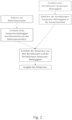
- the temperature is instead determined from the detected voltage drop across the measuring resistor 28.
- the electrical resistance of the measuring resistor 28 is temperature-dependent.
- the relationship between the temperature and the electrical resistance of the measuring resistor 28 is determined in advance and stored in the evaluation circuit 50. For a determined corrected electrical resistance of the measuring resistor 28 or for a determined correction value, the temperature of the measuring resistor 28 can thus be determined from the previously determined relationship.
- a correction value is determined for the voltage drop detected by the voltage detection device 26.
- the current temperature of the measuring resistor 28 is then determined from this correction value or the corrected electrical resistance of the measuring resistor 28 determined using this correction value and the previously determined relationship between the electrical resistance of the measuring resistor 28 and the temperature. Since the measuring resistor is electrically and thermally connected to the battery terminal, this temperature can be used to determine the battery temperature ( Figure 2 ).
- the battery sensor 10 can, for example, also have a plurality of measuring resistors 28, which can be arranged in parallel or in series, wherein a plurality of voltage detection devices 26 can also be provided for detecting the individual voltage drops across the measuring resistors 28.
- the reference current can, for example, be conducted only through individual ones of the measuring resistors 28 in order to better distinguish or separate the voltage drops due to the reference current and the load current.
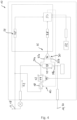
- FIG. 3 For example, an embodiment with two measuring resistors 28a, 28b arranged in series is shown.
- the reference current 42 is fed between the two measuring resistors 28a, 28b arranged in series, i.e., in a sense, it is only applied to one of the two measuring resistors 28a.
- the reference current 42 is applied, only the voltage drop across the measuring resistor 28a changes, while the voltage drop at the second measuring resistor 28b is caused solely by the load current.
- the voltage drop caused by the reference current 42 at the first measuring resistor 28a can be filtered out.
- This method is particularly advantageous when the load current fluctuates greatly, making it difficult to distinguish whether a change in the voltage drop is caused solely by the reference current 42 or by a change in the load current.
- a change in the load current 22 leads to a change in the voltage drop across both measuring resistors 28a, 28b, while a change in the voltage drop caused by the reference current 42 only affects the first measuring resistor 28a.
- the battery sensor 10 shown in FIG. 1 is a schematic representation of the battery sensor 10.
- This battery sensor also includes a temperature sensor 52 connected to the evaluation circuit 50.
- the temperature sensor is located in the battery sensor, for example, on the circuit board on which the evaluation circuit 50 is located, or on the measuring resistor 28.
- the temperature sensor 52 can output a second temperature value to the evaluation circuit.
- the simultaneous detection of a first and a second temperature value can be used, for example, to improve the accuracy of temperature determination.
- the second temperature value can be used, for example, to determine a correction value for the first temperature value, for example, to compensate for aging effects.
- the first temperature value can be used to subject the second temperature value determined by the temperature sensor 52 to a plausibility check. If a defined deviation between the first and second temperature values occurs, for example, an error signal can be output and/or a correction value for the second temperature value can be determined.
Landscapes
- Physics & Mathematics (AREA)
- General Physics & Mathematics (AREA)
- Measurement Of Current Or Voltage (AREA)
- Secondary Cells (AREA)
Claims (9)
- Procédé de fonctionnement d'un capteur de batterie (10), le capteur de batterie (10) comprenant une première connexion (14) et une seconde connexion (16) pour établir un contact avec les pôles (18, 20) d'une batterie (12), au moins une résistance de mesure (28, 28a, 28b) ainsi qu'au moins un dispositif de détection de tension (30, 30a, 30b) pour détecter une chute de tension d'un courant de charge (22) de la batterie (12) passant par le capteur de batterie (10) aux bornes de la résistance de mesure (28, 28a, 28b) et pour fournir en sortie au moins une valeur de mesure dépendant de la chute de tension détectée pour déterminer le courant de charge (22) passant par le capteur de batterie (10) et un circuit d'évaluation (50), comprenant les étapes suivantes :- détermination par le circuit d'évaluation (50) d'une valeur de correction pour la valeur de mesure, et- détermination par le circuit d'évaluation (50) d'une première valeur de température de la résistance de mesure (28, 28a, 28b) sur la base de la valeur de correction déterminée.
- Procédé selon la revendication 1, comprenant les étapes suivantes :- application à la résistance de mesure (28, 28a, 28b) d'un courant de référence de valeur connue,- détection d'une chute de tension provoquée par le courant de référence et/ou d'une variation de la chute de tension provoquée par le courant de référence,- détermination de la valeur de température sur la base de la chute de tension provoquée par le courant de référence et/ou sur la base de la variation de la chute de tension provoquée par le courant de référence.
- Procédé selon la revendication 2, dans lequel le capteur de batterie (10) comprend une pluralité de résistances de mesure (28, 28a, 28b), le capteur de batterie comprenant au moins une première résistance de mesure (28a), parmi les résistances de mesure (28a) et, disposée en série avec celle-ci, une seconde résistance de mesure (28b), parmi les résistances de mesure (28), comprenant respectivement au moins un dispositif de détection de tension pour détecter une chute de tension aux bornes de la résistance de mesure (28a, 28b) respective, comprenant les étapes suivantes :- application à la résistance de mesure (28a) d'un courant de référence de valeur connue,- détection par les dispositifs de détection de tension des chutes de tension aux bornes de la première résistance de mesure et aux bornes de la seconde résistance de mesure,- comparaison des chutes de tension aux bornes de la première résistance de mesure (28a) et de la seconde résistance de mesure (28b) et détermination des chutes de tension sur la base du courant de charge et du courant de référence.
- Procédé selon l'une quelconque des revendications précédentes, comprenant les étapes suivantes :- détection d'une seconde valeur de température,- détermination d'une valeur de correction de température pour la première valeur de température sur la base de la seconde valeur de température.
- Procédé selon la revendication 4, caractérisé en ce que la seconde valeur de température est détectée au moyen d'un capteur, notamment au moyen d'un capteur de température (52).
- Capteur de batterie (10) destiné à détecter une tension d'une batterie (12), notamment d'une batterie de véhicule, comprenant une première connexion (14) et une seconde connexion (16) pour établir un contact avec les pôles (18, 20) d'une batterie (12), au moins une résistance de mesure (28, 28a, 28b), au moins un dispositif de détection de tension (30, 30a, 30b) pour détecter une chute de tension d'un courant de charge (22) de la batterie (12) passant par le capteur de batterie (10) aux bornes de la résistance de mesure (28, 28a, 28b) et pour fournir en sortie au moins une valeur de mesure dépendant de la chute de tension détectée pour déterminer le courant de charge (22) passant par le capteur de batterie (10), et comprenant un circuit d'évaluation (50), le circuit d'évaluation (50) étant conçu pour déterminer une valeur de correction pour la valeur de mesure et pour déterminer une première valeur de température de la résistance de mesure (28, 28a, 28b) sur la base de la valeur de correction déterminée, notamment par un procédé selon l'une quelconque des revendications précédentes.
- Capteur de batterie selon la revendication 6, caractérisé en ce que le capteur de batterie (10) comprend au moins un dispositif à courant de référence (40) destiné à appliquer un courant de référence de valeur connue à au moins une résistance de mesure (28, 28a, 28b).
- Capteur de batterie selon l'une quelconque des revendications 6 et 7, caractérisé en ce que le capteur de batterie (10) comprend une pluralité de résistances de mesure (28, 28a, 28b), le capteur de batterie (10) comprenant au moins une première résistance de mesure (28a), parmi les résistances de mesure (28) et, disposée en série avec celle-ci, une seconde résistance de mesure (28b), parmi les résistances de mesure (28), comprenant respectivement au moins un dispositif de détection de tension (30a, 30b) pour détecter une chute de tension aux bornes de la résistance de mesure (28a, 28b) respective.
- Capteur de batterie selon l'une quelconque des revendications 6 à 8, caractérisé en ce que le capteur de batterie (10) comprend un capteur de température (52) destiné à déterminer une seconde valeur de température, le circuit d'évaluation (50) étant conçu pour déterminer une valeur de correction de température pour la première valeur de température sur la base de la seconde valeur de température.
Applications Claiming Priority (1)
| Application Number | Priority Date | Filing Date | Title |
|---|---|---|---|
| DE102018217528.4A DE102018217528A1 (de) | 2018-10-12 | 2018-10-12 | Verfahren zum Betrieb eines Batteriesensors und Batteriesensor |
Publications (2)
| Publication Number | Publication Date |
|---|---|
| EP3640656A1 EP3640656A1 (fr) | 2020-04-22 |
| EP3640656B1 true EP3640656B1 (fr) | 2025-04-09 |
Family
ID=68136240
Family Applications (1)
| Application Number | Title | Priority Date | Filing Date |
|---|---|---|---|
| EP19201069.2A Active EP3640656B1 (fr) | 2018-10-12 | 2019-10-02 | Procédé de fonctionnement d'un capteur de batterie et capteur de batterie |
Country Status (4)
| Country | Link |
|---|---|
| US (1) | US11656284B2 (fr) |
| EP (1) | EP3640656B1 (fr) |
| CN (1) | CN111044910B (fr) |
| DE (1) | DE102018217528A1 (fr) |
Families Citing this family (1)
| Publication number | Priority date | Publication date | Assignee | Title |
|---|---|---|---|---|
| EP4009507A1 (fr) * | 2020-12-04 | 2022-06-08 | STABL Energy GmbH | Système de stockage de batterie à gestion de température |
Citations (1)
| Publication number | Priority date | Publication date | Assignee | Title |
|---|---|---|---|---|
| US8029187B2 (en) * | 2007-02-21 | 2011-10-04 | Kyocera Corporation | Apparatus, system and method for high resolution identification with temperature dependent resistive device |
Family Cites Families (15)
| Publication number | Priority date | Publication date | Assignee | Title |
|---|---|---|---|---|
| US6028426A (en) * | 1997-08-19 | 2000-02-22 | Statpower Technologies Partnership | Temperature compensated current measurement device |
| JP3691364B2 (ja) | 2000-08-02 | 2005-09-07 | 三洋電機株式会社 | 電流検出装置と電流検出装置を備えるバッテリー装置 |
| US6870357B1 (en) | 2002-11-21 | 2005-03-22 | National Semiconductor Corporation | Method and apparatus for determining the temperature of a junction using voltage responses of the junction and a correction factor |
| DE102004022556B3 (de) * | 2004-05-07 | 2005-10-27 | Siemens Ag | Selbstkalibrierende Vorrichtung zur Spannungsmessung und Verfahren hierfür |
| KR100985667B1 (ko) | 2007-08-22 | 2010-10-05 | 주식회사 엘지화학 | 배터리 개방전압 추정장치, 이를 이용한 배터리 충전상태추정장치 및 그 제어 방법 |
| DE102011083307A1 (de) | 2011-09-23 | 2013-03-28 | Continental Automotive Gmbh | Vorrichtung zur Messung eines Batteriestroms |
| EP2623996B1 (fr) * | 2012-02-02 | 2014-05-21 | MAGNA STEYR Battery Systems GmbH & Co OG | Circuit de mesure de courant et procédé de surveillance d'un fonctionnement d'un circuit de mesure de courant |
| JP2014016297A (ja) * | 2012-07-11 | 2014-01-30 | Yazaki Corp | シャント抵抗式電流センサ |
| DE102014213731A1 (de) * | 2014-07-15 | 2016-01-21 | Robert Bosch Gmbh | Verfahren und Vorrichtung zum Messen des elektrischen Stroms einer Batterie mit mehreren Batteriemodulen |
| WO2016042091A1 (fr) * | 2014-09-17 | 2016-03-24 | Continental Teves Ag & Co. Ohg | Étalonnage de capteurs de courant au moyen du courant de référence pendant la mesure du courant |
| CN105467324B (zh) | 2014-09-30 | 2020-03-03 | 株式会社杰士汤浅国际 | 电池劣化判定装置、电池劣化判定方法以及电池组 |
| JP6478661B2 (ja) | 2015-01-29 | 2019-03-06 | ルネサスエレクトロニクス株式会社 | バッテリセルの電圧補正方法、バッテリ監視装置、半導体チップ及び車両 |
| CN105652207A (zh) | 2015-12-31 | 2016-06-08 | 浙江华丰电动工具有限公司 | 一种动力型锂电池电量监控装置及监控方法 |
| DE102016204941B4 (de) | 2016-03-24 | 2025-12-11 | Continental Automotive Technologies GmbH | Verfahren zum Bestimmen eines Laststroms und Batteriesensor |
| DE102017221612A1 (de) | 2017-11-30 | 2019-06-06 | Continental Automotive Gmbh | Stromsensor und Verfahren zum Messen eines elektrischen Stroms |
-
2018
- 2018-10-12 DE DE102018217528.4A patent/DE102018217528A1/de not_active Withdrawn
-
2019
- 2019-10-02 EP EP19201069.2A patent/EP3640656B1/fr active Active
- 2019-10-10 US US16/598,022 patent/US11656284B2/en active Active
- 2019-10-11 CN CN201910961626.1A patent/CN111044910B/zh active Active
Patent Citations (1)
| Publication number | Priority date | Publication date | Assignee | Title |
|---|---|---|---|---|
| US8029187B2 (en) * | 2007-02-21 | 2011-10-04 | Kyocera Corporation | Apparatus, system and method for high resolution identification with temperature dependent resistive device |
Also Published As
| Publication number | Publication date |
|---|---|
| EP3640656A1 (fr) | 2020-04-22 |
| CN111044910B (zh) | 2023-04-18 |
| DE102018217528A1 (de) | 2020-04-16 |
| US20200116794A1 (en) | 2020-04-16 |
| CN111044910A (zh) | 2020-04-21 |
| US11656284B2 (en) | 2023-05-23 |
Similar Documents
| Publication | Publication Date | Title |
|---|---|---|
| EP3701274A1 (fr) | Procédé pour faire fonctionner un capteur de batterie et capteur de batterie | |
| EP3640651B1 (fr) | Procédé de fonctionnement d'un capteur de courant et capteur de courant | |
| DE102017223535A1 (de) | Verfahren und Batteriesensor zur Ermittlung eines Laststroms | |
| DE10149982B4 (de) | Verfahren zur Ermittlung der Temperatur einer elektrischen Spule sowie zugehörige Vorrichtung | |
| DE102010009835A1 (de) | Elektronisches Bauelement insbesondere Stromsensor | |
| DE102019218308A1 (de) | Widerstandsbaugruppe für Stromsensor sowie Stromsensor und Verfahren zur Messung eines Batteriestroms | |
| DE102014219238A1 (de) | Überstromerkennung im Stromsensor mit Hallsensor | |
| DE19729697C1 (de) | Anordnung zum Bestimmen der relativen Luftfeuchte | |
| DE102022207853A1 (de) | Stromsensor | |
| DE102017221612A1 (de) | Stromsensor und Verfahren zum Messen eines elektrischen Stroms | |
| EP1213189B1 (fr) | Dispositif pour surveiller le réseau de bord d'un véhicule | |
| WO2012110224A1 (fr) | Circuit destiné au chauffage électrique d'un siège | |
| DE102010003125B4 (de) | Vorrichtung zur Temperaturmessung | |
| EP3640652B1 (fr) | Procédé de fonctionnement d'un capteur de batterie et capteur de batterie | |
| DE102013213566A1 (de) | Vorrichtung und Verfahren zur Messung einer Stromstärke | |
| EP3637116B1 (fr) | Détecteur et procédé de vérification d'un détecteur | |
| EP1818536A2 (fr) | Procédé et dispositif de surveillance d'au moins une bougie de préchauffage d'un véhicule automobile | |
| EP3640656A1 (fr) | Procédé de fonctionnement d'un capteur de batterie et capteur de batterie | |
| EP3233578B1 (fr) | Dispositif de surveillance pour au moins un circuit d'allumage pour un moyen de protection de personnes pour un véhicule, et procédé servant à faire fonctionner un dispositif de surveillance | |
| DE102018217600A1 (de) | Verfahren und Batteriesensor zur Branderkennung in einem Fahrzeug und Fahrzeug | |
| EP1879005B1 (fr) | Procédé destiné à la vérification d'un capteur de température doté d'au moins deux résistances sensibles à la température | |
| EP4312047A1 (fr) | Capteur de courant | |
| DE102006030337B4 (de) | Verfahren zur Steuerung einer Sitzheizung eines Fahrzeugsitzes, sowie Sitzheizung | |
| WO2020043780A1 (fr) | Capteur de batterie et procédé de fonctionnement d'un capteur de batterie | |
| DE102019215754A1 (de) | Verfahren zum Betrieb eines Stromsensors und Stromsensor |
Legal Events
| Date | Code | Title | Description |
|---|---|---|---|
| PUAI | Public reference made under article 153(3) epc to a published international application that has entered the european phase |
Free format text: ORIGINAL CODE: 0009012 |
|
| STAA | Information on the status of an ep patent application or granted ep patent |
Free format text: STATUS: THE APPLICATION HAS BEEN PUBLISHED |
|
| AK | Designated contracting states |
Kind code of ref document: A1 Designated state(s): AL AT BE BG CH CY CZ DE DK EE ES FI FR GB GR HR HU IE IS IT LI LT LU LV MC MK MT NL NO PL PT RO RS SE SI SK SM TR |
|
| AX | Request for extension of the european patent |
Extension state: BA ME |
|
| STAA | Information on the status of an ep patent application or granted ep patent |
Free format text: STATUS: REQUEST FOR EXAMINATION WAS MADE |
|
| 17P | Request for examination filed |
Effective date: 20201022 |
|
| RBV | Designated contracting states (corrected) |
Designated state(s): AL AT BE BG CH CY CZ DE DK EE ES FI FR GB GR HR HU IE IS IT LI LT LU LV MC MK MT NL NO PL PT RO RS SE SI SK SM TR |
|
| RAP1 | Party data changed (applicant data changed or rights of an application transferred) |
Owner name: CONTINENTAL AUTOMOTIVE TECHNOLOGIES GMBH |
|
| STAA | Information on the status of an ep patent application or granted ep patent |
Free format text: STATUS: EXAMINATION IS IN PROGRESS |
|
| 17Q | First examination report despatched |
Effective date: 20221124 |
|
| RAP3 | Party data changed (applicant data changed or rights of an application transferred) |
Owner name: CONTINENTAL AUTOMOTIVE TECHNOLOGIES GMBH |
|
| GRAP | Despatch of communication of intention to grant a patent |
Free format text: ORIGINAL CODE: EPIDOSNIGR1 |
|
| STAA | Information on the status of an ep patent application or granted ep patent |
Free format text: STATUS: GRANT OF PATENT IS INTENDED |
|
| RIC1 | Information provided on ipc code assigned before grant |
Ipc: G01K 7/16 20060101ALI20241113BHEP Ipc: G01R 35/00 20060101ALI20241113BHEP Ipc: G01R 31/374 20190101ALI20241113BHEP Ipc: G01R 31/364 20190101AFI20241113BHEP |
|
| INTG | Intention to grant announced |
Effective date: 20241126 |
|
| GRAS | Grant fee paid |
Free format text: ORIGINAL CODE: EPIDOSNIGR3 |
|
| GRAA | (expected) grant |
Free format text: ORIGINAL CODE: 0009210 |
|
| STAA | Information on the status of an ep patent application or granted ep patent |
Free format text: STATUS: THE PATENT HAS BEEN GRANTED |
|
| AK | Designated contracting states |
Kind code of ref document: B1 Designated state(s): AL AT BE BG CH CY CZ DE DK EE ES FI FR GB GR HR HU IE IS IT LI LT LU LV MC MK MT NL NO PL PT RO RS SE SI SK SM TR |
|
| REG | Reference to a national code |
Ref country code: GB Ref legal event code: FG4D Free format text: NOT ENGLISH |
|
| REG | Reference to a national code |
Ref country code: CH Ref legal event code: EP |
|
| REG | Reference to a national code |
Ref country code: DE Ref legal event code: R096 Ref document number: 502019013170 Country of ref document: DE |
|
| REG | Reference to a national code |
Ref country code: IE Ref legal event code: FG4D Free format text: LANGUAGE OF EP DOCUMENT: GERMAN |
|
| REG | Reference to a national code |
Ref country code: NL Ref legal event code: MP Effective date: 20250409 |
|
| PG25 | Lapsed in a contracting state [announced via postgrant information from national office to epo] |
Ref country code: NL Free format text: LAPSE BECAUSE OF FAILURE TO SUBMIT A TRANSLATION OF THE DESCRIPTION OR TO PAY THE FEE WITHIN THE PRESCRIBED TIME-LIMIT Effective date: 20250409 |
|
| PG25 | Lapsed in a contracting state [announced via postgrant information from national office to epo] |
Ref country code: ES Free format text: LAPSE BECAUSE OF FAILURE TO SUBMIT A TRANSLATION OF THE DESCRIPTION OR TO PAY THE FEE WITHIN THE PRESCRIBED TIME-LIMIT Effective date: 20250409 Ref country code: FI Free format text: LAPSE BECAUSE OF FAILURE TO SUBMIT A TRANSLATION OF THE DESCRIPTION OR TO PAY THE FEE WITHIN THE PRESCRIBED TIME-LIMIT Effective date: 20250409 Ref country code: PT Free format text: LAPSE BECAUSE OF FAILURE TO SUBMIT A TRANSLATION OF THE DESCRIPTION OR TO PAY THE FEE WITHIN THE PRESCRIBED TIME-LIMIT Effective date: 20250811 |
|
| REG | Reference to a national code |
Ref country code: LT Ref legal event code: MG9D |
|
| PG25 | Lapsed in a contracting state [announced via postgrant information from national office to epo] |
Ref country code: GR Free format text: LAPSE BECAUSE OF FAILURE TO SUBMIT A TRANSLATION OF THE DESCRIPTION OR TO PAY THE FEE WITHIN THE PRESCRIBED TIME-LIMIT Effective date: 20250710 Ref country code: NO Free format text: LAPSE BECAUSE OF FAILURE TO SUBMIT A TRANSLATION OF THE DESCRIPTION OR TO PAY THE FEE WITHIN THE PRESCRIBED TIME-LIMIT Effective date: 20250709 |
|
| PG25 | Lapsed in a contracting state [announced via postgrant information from national office to epo] |
Ref country code: PL Free format text: LAPSE BECAUSE OF FAILURE TO SUBMIT A TRANSLATION OF THE DESCRIPTION OR TO PAY THE FEE WITHIN THE PRESCRIBED TIME-LIMIT Effective date: 20250409 |
|
| PG25 | Lapsed in a contracting state [announced via postgrant information from national office to epo] |
Ref country code: BG Free format text: LAPSE BECAUSE OF FAILURE TO SUBMIT A TRANSLATION OF THE DESCRIPTION OR TO PAY THE FEE WITHIN THE PRESCRIBED TIME-LIMIT Effective date: 20250409 |
|
| PG25 | Lapsed in a contracting state [announced via postgrant information from national office to epo] |
Ref country code: HR Free format text: LAPSE BECAUSE OF FAILURE TO SUBMIT A TRANSLATION OF THE DESCRIPTION OR TO PAY THE FEE WITHIN THE PRESCRIBED TIME-LIMIT Effective date: 20250409 |
|
| PG25 | Lapsed in a contracting state [announced via postgrant information from national office to epo] |
Ref country code: RS Free format text: LAPSE BECAUSE OF FAILURE TO SUBMIT A TRANSLATION OF THE DESCRIPTION OR TO PAY THE FEE WITHIN THE PRESCRIBED TIME-LIMIT Effective date: 20250709 |
|
| REG | Reference to a national code |
Ref country code: CH Ref legal event code: W10 Free format text: ST27 STATUS EVENT CODE: U-0-0-W10-W00 (AS PROVIDED BY THE NATIONAL OFFICE) Effective date: 20251022 |
|
| PG25 | Lapsed in a contracting state [announced via postgrant information from national office to epo] |
Ref country code: IS Free format text: LAPSE BECAUSE OF FAILURE TO SUBMIT A TRANSLATION OF THE DESCRIPTION OR TO PAY THE FEE WITHIN THE PRESCRIBED TIME-LIMIT Effective date: 20250809 |
|
| PG25 | Lapsed in a contracting state [announced via postgrant information from national office to epo] |
Ref country code: LV Free format text: LAPSE BECAUSE OF FAILURE TO SUBMIT A TRANSLATION OF THE DESCRIPTION OR TO PAY THE FEE WITHIN THE PRESCRIBED TIME-LIMIT Effective date: 20250409 |
|
| RAP4 | Party data changed (patent owner data changed or rights of a patent transferred) |
Owner name: AUMOVIO GERMANY GMBH |
|
| PGFP | Annual fee paid to national office [announced via postgrant information from national office to epo] |
Ref country code: DE Payment date: 20251031 Year of fee payment: 7 |
|
| REG | Reference to a national code |
Ref country code: DE Ref legal event code: R097 Ref document number: 502019013170 Country of ref document: DE |
|
| PG25 | Lapsed in a contracting state [announced via postgrant information from national office to epo] |
Ref country code: DK Free format text: LAPSE BECAUSE OF FAILURE TO SUBMIT A TRANSLATION OF THE DESCRIPTION OR TO PAY THE FEE WITHIN THE PRESCRIBED TIME-LIMIT Effective date: 20250409 Ref country code: SM Free format text: LAPSE BECAUSE OF FAILURE TO SUBMIT A TRANSLATION OF THE DESCRIPTION OR TO PAY THE FEE WITHIN THE PRESCRIBED TIME-LIMIT Effective date: 20250409 |
|
| PG25 | Lapsed in a contracting state [announced via postgrant information from national office to epo] |
Ref country code: CZ Free format text: LAPSE BECAUSE OF FAILURE TO SUBMIT A TRANSLATION OF THE DESCRIPTION OR TO PAY THE FEE WITHIN THE PRESCRIBED TIME-LIMIT Effective date: 20250409 |
|
| PG25 | Lapsed in a contracting state [announced via postgrant information from national office to epo] |
Ref country code: EE Free format text: LAPSE BECAUSE OF FAILURE TO SUBMIT A TRANSLATION OF THE DESCRIPTION OR TO PAY THE FEE WITHIN THE PRESCRIBED TIME-LIMIT Effective date: 20250409 |
|
| REG | Reference to a national code |
Ref country code: DE Ref legal event code: R081 Ref document number: 502019013170 Country of ref document: DE Owner name: AUMOVIO GERMANY GMBH, DE Free format text: FORMER OWNER: CONTINENTAL AUTOMOTIVE TECHNOLOGIES GMBH, 30175 HANNOVER, DE |
|
| PG25 | Lapsed in a contracting state [announced via postgrant information from national office to epo] |
Ref country code: SK Free format text: LAPSE BECAUSE OF FAILURE TO SUBMIT A TRANSLATION OF THE DESCRIPTION OR TO PAY THE FEE WITHIN THE PRESCRIBED TIME-LIMIT Effective date: 20250409 Ref country code: RO Free format text: LAPSE BECAUSE OF FAILURE TO SUBMIT A TRANSLATION OF THE DESCRIPTION OR TO PAY THE FEE WITHIN THE PRESCRIBED TIME-LIMIT Effective date: 20250409 |
|
| PG25 | Lapsed in a contracting state [announced via postgrant information from national office to epo] |
Ref country code: IT Free format text: LAPSE BECAUSE OF FAILURE TO SUBMIT A TRANSLATION OF THE DESCRIPTION OR TO PAY THE FEE WITHIN THE PRESCRIBED TIME-LIMIT Effective date: 20250409 |
|
| PLBE | No opposition filed within time limit |
Free format text: ORIGINAL CODE: 0009261 |
|
| STAA | Information on the status of an ep patent application or granted ep patent |
Free format text: STATUS: NO OPPOSITION FILED WITHIN TIME LIMIT |
|
| REG | Reference to a national code |
Ref country code: CH Ref legal event code: L10 Free format text: ST27 STATUS EVENT CODE: U-0-0-L10-L00 (AS PROVIDED BY THE NATIONAL OFFICE) Effective date: 20260218 |
|
| 26N | No opposition filed |
Effective date: 20260112 |
|
| REG | Reference to a national code |
Ref country code: CH Ref legal event code: H13 Free format text: ST27 STATUS EVENT CODE: U-0-0-H10-H13 (AS PROVIDED BY THE NATIONAL OFFICE) Effective date: 20260527 |
|
| PG25 | Lapsed in a contracting state [announced via postgrant information from national office to epo] |
Ref country code: LU Free format text: LAPSE BECAUSE OF NON-PAYMENT OF DUE FEES Effective date: 20251002 |
|
| REG | Reference to a national code |
Ref country code: BE Ref legal event code: MM Effective date: 20251031 |
|
| GBPC | Gb: european patent ceased through non-payment of renewal fee |
Effective date: 20251002 |
|
| PG25 | Lapsed in a contracting state [announced via postgrant information from national office to epo] |
Ref country code: LT Free format text: LAPSE BECAUSE OF FAILURE TO SUBMIT A TRANSLATION OF THE DESCRIPTION OR TO PAY THE FEE WITHIN THE PRESCRIBED TIME-LIMIT Effective date: 20250409 |
|
| PG25 | Lapsed in a contracting state [announced via postgrant information from national office to epo] |
Ref country code: MC Free format text: LAPSE BECAUSE OF FAILURE TO SUBMIT A TRANSLATION OF THE DESCRIPTION OR TO PAY THE FEE WITHIN THE PRESCRIBED TIME-LIMIT Effective date: 20250409 |
|
| PG25 | Lapsed in a contracting state [announced via postgrant information from national office to epo] |
Ref country code: GB Free format text: LAPSE BECAUSE OF NON-PAYMENT OF DUE FEES Effective date: 20251002 |
|
| PG25 | Lapsed in a contracting state [announced via postgrant information from national office to epo] |
Ref country code: BE Free format text: LAPSE BECAUSE OF NON-PAYMENT OF DUE FEES Effective date: 20251031 Ref country code: CH Free format text: LAPSE BECAUSE OF NON-PAYMENT OF DUE FEES Effective date: 20251031 |
|
| PG25 | Lapsed in a contracting state [announced via postgrant information from national office to epo] |
Ref country code: FR Free format text: LAPSE BECAUSE OF NON-PAYMENT OF DUE FEES Effective date: 20251031 |
|
| PG25 | Lapsed in a contracting state [announced via postgrant information from national office to epo] |
Ref country code: SE Free format text: LAPSE BECAUSE OF FAILURE TO SUBMIT A TRANSLATION OF THE DESCRIPTION OR TO PAY THE FEE WITHIN THE PRESCRIBED TIME-LIMIT Effective date: 20250409 |