EP3640700A1 - Linsensystem, kamerasystem und abbildungssystem - Google Patents
Linsensystem, kamerasystem und abbildungssystem Download PDFInfo
- Publication number
- EP3640700A1 EP3640700A1 EP18818135.8A EP18818135A EP3640700A1 EP 3640700 A1 EP3640700 A1 EP 3640700A1 EP 18818135 A EP18818135 A EP 18818135A EP 3640700 A1 EP3640700 A1 EP 3640700A1
- Authority
- EP
- European Patent Office
- Prior art keywords
- lens
- imaging element
- lens system
- image
- respect
- Prior art date
- Legal status (The legal status is an assumption and is not a legal conclusion. Google has not performed a legal analysis and makes no representation as to the accuracy of the status listed.)
- Granted
Links
Images






Classifications
-
- G—PHYSICS
- G02—OPTICS
- G02B—OPTICAL ELEMENTS, SYSTEMS OR APPARATUS
- G02B13/00—Optical objectives specially designed for the purposes specified below
- G02B13/18—Optical objectives specially designed for the purposes specified below with lenses having one or more non-spherical faces, e.g. for reducing geometrical aberration
-
- G—PHYSICS
- G02—OPTICS
- G02B—OPTICAL ELEMENTS, SYSTEMS OR APPARATUS
- G02B9/00—Optical objectives characterised both by the number of the components and their arrangements according to their sign, i.e. + or -
- G02B9/64—Optical objectives characterised both by the number of the components and their arrangements according to their sign, i.e. + or - having more than six components
-
- G—PHYSICS
- G02—OPTICS
- G02B—OPTICAL ELEMENTS, SYSTEMS OR APPARATUS
- G02B13/00—Optical objectives specially designed for the purposes specified below
- G02B13/001—Miniaturised objectives for electronic devices, e.g. portable telephones, webcams, PDAs, small digital cameras
- G02B13/0015—Miniaturised objectives for electronic devices, e.g. portable telephones, webcams, PDAs, small digital cameras characterised by the lens design
- G02B13/002—Miniaturised objectives for electronic devices, e.g. portable telephones, webcams, PDAs, small digital cameras characterised by the lens design having at least one aspherical surface
- G02B13/0045—Miniaturised objectives for electronic devices, e.g. portable telephones, webcams, PDAs, small digital cameras characterised by the lens design having at least one aspherical surface having five or more lenses
-
- G—PHYSICS
- G02—OPTICS
- G02B—OPTICAL ELEMENTS, SYSTEMS OR APPARATUS
- G02B13/00—Optical objectives specially designed for the purposes specified below
- G02B13/04—Reversed telephoto objectives
-
- G—PHYSICS
- G02—OPTICS
- G02B—OPTICAL ELEMENTS, SYSTEMS OR APPARATUS
- G02B13/00—Optical objectives specially designed for the purposes specified below
- G02B13/08—Anamorphotic objectives
-
- G—PHYSICS
- G03—PHOTOGRAPHY; CINEMATOGRAPHY; ANALOGOUS TECHNIQUES USING WAVES OTHER THAN OPTICAL WAVES; ELECTROGRAPHY; HOLOGRAPHY
- G03B—APPARATUS OR ARRANGEMENTS FOR TAKING PHOTOGRAPHS OR FOR PROJECTING OR VIEWING THEM; APPARATUS OR ARRANGEMENTS EMPLOYING ANALOGOUS TECHNIQUES USING WAVES OTHER THAN OPTICAL WAVES; ACCESSORIES THEREFOR
- G03B17/00—Details of cameras or camera bodies; Accessories therefor
- G03B17/02—Bodies
- G03B17/12—Bodies with means for supporting objectives, supplementary lenses, filters, masks, or turrets
-
- G—PHYSICS
- G02—OPTICS
- G02B—OPTICAL ELEMENTS, SYSTEMS OR APPARATUS
- G02B13/00—Optical objectives specially designed for the purposes specified below
- G02B13/06—Panoramic objectives; So-called "sky lenses" including panoramic objectives having reflecting surfaces
-
- G—PHYSICS
- G02—OPTICS
- G02B—OPTICAL ELEMENTS, SYSTEMS OR APPARATUS
- G02B27/00—Optical systems or apparatus not provided for by any of the groups G02B1/00 - G02B26/00, G02B30/00
- G02B27/0025—Optical systems or apparatus not provided for by any of the groups G02B1/00 - G02B26/00, G02B30/00 for optical correction, e.g. distorsion, aberration
-
- G—PHYSICS
- G02—OPTICS
- G02B—OPTICAL ELEMENTS, SYSTEMS OR APPARATUS
- G02B5/00—Optical elements other than lenses
- G02B5/005—Diaphragms
-
- H—ELECTRICITY
- H04—ELECTRIC COMMUNICATION TECHNIQUE
- H04N—PICTORIAL COMMUNICATION, e.g. TELEVISION
- H04N23/00—Cameras or camera modules comprising electronic image sensors; Control thereof
- H04N23/50—Constructional details
- H04N23/55—Optical parts specially adapted for electronic image sensors; Mounting thereof
-
- H—ELECTRICITY
- H04—ELECTRIC COMMUNICATION TECHNIQUE
- H04N—PICTORIAL COMMUNICATION, e.g. TELEVISION
- H04N23/00—Cameras or camera modules comprising electronic image sensors; Control thereof
- H04N23/60—Control of cameras or camera modules
- H04N23/698—Control of cameras or camera modules for achieving an enlarged field of view, e.g. panoramic image capture
Definitions
- the present disclosure relates to a lens system, a camera system, and an imaging system.
- a quadrilateral image formed by a lens that does not conform to a central projection style may collapse.
- an optical image and the imaging element do not fully overlap with each other, increasing an unused region on a photosensitive surface.
- PTL 1 discloses a method for capturing a panoramic image using an image sensor having an oblong shape.
- PTL 1 discloses that a toric lens is used as a fisheye objective lens to convert a circular image into a quadrilateral image to allow a quadrilateral imaging element to form the image.
- a lens system capable of effectively utilizing a region of a photosensitive surface of a quadrilateral imaging element, and expanding a subject at a central portion around an optical axis, and a camera system and an imaging system including the lens system are provided.
- a lens system is a lens system configured to form an image on an imaging element having a quadrilateral shape disposed on an optical axis, and includes a first free-curved lens being asymmetrical with respect to the optical axis.
- a free-curved surface of the first free-curved lens has negative refractive power with respect to a ray parallel to the optical axis at an intersection point between a circle separated from the optical axis by a length having a predetermined ratio with respect to a minimum image height and a first surface passing through the optical axis and parallel to longer sides of the imaging element, and positive refractive power with respect to a ray parallel to the optical axis at an intersection point between a circle separated from the optical axis by a length having a predetermined ratio with respect to the minimum image height and a second surface passing through the optical axis and parallel to shorter sides of the imaging element.
- a camera system includes the lens system according to the present disclosure, described above, and a quadrilateral imaging element disposed at a position at which the lens system forms an image on the optical axis.
- An imaging system includes the lens system according to the present disclosure, described above, a quadrilateral imaging element disposed at a position at which the lens system forms an image on the optical axis, and an image processor configured to process the image generated by the imaging element.
- the present invention can achieve a lens system configured to form an approximately quadrilateral image, and to expand a subject at a central portion around an optical axis, and a camera system and an imaging system including the lens system.
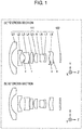
- FIG. 1 is a layout diagram of a lens system according to a first exemplary embodiment, illustrating an infinity focusing state.
- Part (a) of FIG. 1 is a YZ cross-section
- part (b) of FIG. 1 is an XZ cross-section, each illustrating lens system 111 including eight lens elements, and quadrilateral imaging element 102 having shorter sides and longer sides.
- An X direction is a direction parallel to the longer sides of imaging element 102.
- a Y direction is a direction parallel to a shorter side direction of imaging element 102.
- a Z direction is a direction parallel to an optical axis.
- the YZ cross-section includes the optical axis, and is a plane parallel to the Y direction and the Z direction.
- the XZ cross-section includes the optical axis, and is a plane parallel to the X direction and the Z direction.
- lens system 111 includes, in order from an object side to an image surface side, five lens elements L1 to L5, aperture diaphragm A, and three lens elements L6 to L8.
- a position at which lens system 111 forms an image corresponds to an image surface of imaging element 102.
- reference marks are omitted.
- Lens system 111 includes, in order from the object side to the image surface side, lens element L1 having a negative meniscus shape where a convex surface faces the object side, lens element L2 having both surfaces formed into concave shapes, lens element L3 having both surfaces formed into concave shapes, lens element L4 having both surfaces formed into convex shapes, lens element L5 having a positive meniscus shape where both surfaces are formed into aspherical shapes and a convex surface faces the object side, aperture diaphragm A, lens element L6 having both surfaces formed into convex shapes, lens element L7 having a negative meniscus shape where a convex surface faces the image surface side, and lens element L8 having a positive meniscus shape where a convex surface faces the object side. Lens element L6 and lens element L7 are joined with each other.
- lens element L1 is an example of a first lens element
- lens element L2 is an example of a second lens element.
- lens element L3 and lens element L8 each have both surfaces respectively facing the object side and the image surface side and being XY-polynomial, free-curved surfaces.
- the free-curved surfaces are each added with an asterisk "*".
- lens element L3 is an example of a first free-curved lens
- lens element L8 is an example of a second free-curved lens.
- the free-curved surface, facing the image surface side, of lens element L3 has negative refractive power with respect to a ray parallel to the optical axis at an intersection point between a circle separated from the optical axis by a length having a predetermined ratio with respect to a minimum image height and an XZ plane (first surface) passing through the optical axis and parallel to the longer sides of the imaging element, and positive refractive power with respect to a ray parallel to the optical axis at an intersection point between a circle separated from the optical axis by a length having a predetermined ratio with respect to the minimum image height and a YZ plane (second surface) passing through the optical axis and parallel to the shorter sides of the imaging element.
- all ratios correspond to the predetermined ratio with respect to the minimum image height.
- the free-curved surface, facing the image surface side, of lens element L3 has negative refractive power with respect to a ray parallel to the optical axis at all intersection points with the XZ plane, and positive refractive power with respect to a ray parallel to the optical axis at all intersection points with the YZ plane.
- Surface data of the lens elements will be described later. Shapes of surfaces of free-curved lenses and aspherical lenses correspond to shapes around the optical axis (peak) in the Y direction.
- FIG. 2 is a layout diagram of a lens system according to a second exemplary embodiment. Part (a) of FIG. 2 is a YZ cross-section, and part (b) of FIG. 2 is an XZ cross-section, each illustrating lens system 121 including eight lens elements, and quadrilateral imaging element 102 having shorter sides and longer sides. In part (b) of FIG. 2 , reference marks are omitted.
- lens system 121 according to the second exemplary embodiment is identical in number, kinds, and a disposition order of lens elements, but differs in surface data of lens system elements L1 to L8. Differences in surface data will be described later.
- lens element L1 is an example of a first lens element
- lens element L2 is an example of a second lens element
- lens element L3 is an example of a first free-curved lens
- lens element L8 is an example of a second free-curved lens.
- the free-curved surface, facing the image surface side, of lens element L3 has negative refractive power with respect to a ray parallel to the optical axis at all intersection points with the XZ plane, and positive refractive power with respect to a ray parallel to the optical axis at all intersection points with the YZ plane.
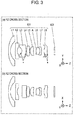
- FIG. 3 is a layout diagram of a lens system according to a third exemplary embodiment. Part (a) of FIG. 3 is a YZ cross-section, and part (b) of FIG. 3 is an XZ cross-section, each illustrating lens system 131 including eight lens elements, and quadrilateral imaging element 102 having shorter sides and longer sides. In part (b) of FIG. 3 , reference marks are omitted.
- lens system 131 according to the third exemplary embodiment is identical in number of lens elements, but differs in kind of lens element L2 and surface data of lens system elements L1 to L8.
- Lens element L2 has a negative meniscus shape where a convex surface faces the object side.
- lens element L1 is an example of a first lens element
- lens element L2 is an example of a second lens element
- lens element L3 is an example of a first free-curved lens
- lens element L8 is an example of a second free-curved lens.
- the free-curved surface, facing the image surface side, of lens element L3 has negative refractive power with respect to a ray parallel to the optical axis at all intersection points with the XZ plane, and positive refractive power with respect to a ray parallel to the optical axis at all intersection points with the YZ plane.
- the lens systems according to the first to third exemplary embodiments each include a plurality of lens elements to form an image on quadrilateral imaging element 102 having the shorter sides and the longer sides.
- the lens systems each include, as lens elements, the free-curved lenses that are rotational asymmetrical with respect to the optical axis. That is, the lens systems each include, in order from the object side to the image surface side, a plurality of the lens elements, an aperture diaphragm, and a plurality of the lens elements. With this configuration, an approximately quadrilateral image that is almost quadrilateral can be formed.
- the lens systems according to the first to third exemplary embodiments each have such a configuration that includes at least three or more lens elements that are rotational symmetrical with respect to the optical axis. With this configuration, free-curved lenses have been reduced in number, minimizing unevenness in capability due to directions. Furthermore, the lens systems according to the first to third exemplary embodiments can advantageously shorten calculation periods during designing.
- the lens systems according to the first to third exemplary embodiments are advantageous in terms of that position control for image heights and aberration reductions can be easily performed.
- a lens system configured to form an image on a quadrilateral imaging element disposed on an optical axis includes a first free-curved lens being asymmetrical with respect to the optical axis.
- a free-curved surface of the first free-curved lens has negative refractive power with respect to a ray parallel to the optical axis at an intersection point between a circle separated from the optical axis by a length having a predetermined ratio with respect to a minimum image height and an XZ plane passing through the optical axis and parallel to the longer sides of the imaging element, and positive refractive power with respect to a ray parallel to the optical axis at an intersection point between a circle separated from the optical axis by a length having a predetermined ratio with respect to the minimum image height and a YZ plane passing through the optical axis and parallel to the shorter sides of the imaging element (hereinafter, the configuration is referred to as a basic configuration of the exemplary embodiments).
- the predetermined ratio with respect to the minimum image height preferably ranges from 40% to 80% inclusive, and more preferably is 60%.
- the free-curved surface as can be seen on the first free-curved lens allows expanding an image at a central portion of an image circle around an optical axis, and capturing a subject present around the optical axis in an enlarged manner, leading to a higher detection and recognition rate. Furthermore, an image circle of a fisheye lens, which is normally circular, can be expanded in the longer side direction in particular. With a portion where positive and negative inversion occurs in refractive power of a free-curved surface, fine image-expanding effects can be achieved.
- a first free-curved lens does not have a free-curved surface having negative refractive power with respect to a ray parallel to the optical axis at an intersection point between a circle separated from the optical axis by a length having a predetermined ratio with respect to a minimum image height and an XZ plane, and positive refractive power with respect to a ray parallel to the optical axis at an intersection point between a circle separated from the optical axis by a length having a predetermined ratio with respect to the minimum image height and a YZ plane, an image cannot be fully expanded at a central region of a photosensitive surface of a quadrilateral imaging element. Otherwise, lens elements may increase in number, expanding a lens system in size. Such a lens having a free-curved surface, as described above, which has been difficult to manufacture so far, has become possible to manufacture as processing and molding techniques have been advancing in recent years.
- a lens system having the basic configuration of the present exemplary embodiments as can be seen in the lens systems according to the first to third exemplary embodiments, for example, satisfy the following condition (1). ⁇ LONG > 60 ° where,
- a lens system having the basic configuration of the present exemplary embodiments as can be seen in the lens systems according to the first to third exemplary embodiments, for example, satisfy the following condition (4). ⁇ LONG ⁇ ⁇ SHORT > 0 where,
- a lens system having the basic configuration of the present exemplary embodiments as can be seen in the lens systems according to the first to third exemplary embodiments, for example, satisfy the following condition (6).
- n FREE ⁇ 1.7 where,
- a lens system having the basic configuration of the present exemplary embodiments include aperture diaphragm A between an object and an imaging element, and satisfy the following condition (7). ⁇ 3 ⁇ N o ⁇ N i ⁇ 3 where,
- a lens system having the basic configuration of the present exemplary embodiments include aperture diaphragm A between the object and imaging element 102, at least one first free-curved lens closer to the object than aperture diaphragm A is, and at least one second free-curved lens closer to the image surface than aperture diaphragm A is.
- Adopting the configuration described above is advantageous in terms of that curvatures of image surface can be reduced in any directions including the longer side direction, the shorter side direction, and a diagonal direction.
- imaging element 102 do not include an image circle of the lens system.
- a lens system using a free-curved lens securing resolution around ends of an image circle is difficult in terms of designing and manufacturing.
- the lenses configuring the lens systems according to the first to third exemplary embodiments have symmetrical surfaces with respect to the longer sides or the shorter sides of imaging element 102. However, even when asymmetrical surfaces are used, enough effects can be achieved, as long as the basic configuration of the present exemplary embodiments and the conditions are satisfied.
- FIG. 4 is a schematic block diagram of a camera system according to a fourth exemplary embodiment.
- Camera system 100 according to the fourth exemplary embodiment includes lens system 111, imaging element 102 configured to receive an optical image formed by lens system 111 and to convert the received optical image into an electrical image signal, and camera main body 103.
- the lens system of the fourth exemplary embodiment can be one of the lens systems according to the first to third exemplary embodiments.
- FIG. 4 illustrates a case where lens system 111 according to the first exemplary embodiment is used as a lens system.
- Imaging element 102 can thus form an approximately quadrilateral image.
- Camera system 100 capable of effectively utilizing the region of the photosensitive surface of imaging element 102 having a quadrilateral shape to obtain an image can be achieved.
- FIG. 5 is a schematic block diagram of an imaging system according to a fifth exemplary embodiment.
- imaging optical system 201 used in imaging system 200 according to the fifth exemplary embodiment includes one of the lens systems according to the first to third exemplary embodiments.
- image processor 202 may be provided inside or outside of camera main body 103 (see FIG. 4 ).
- a first numerical value example in which lens system 111 according to the first exemplary embodiment has been specifically implemented will be described herein.
- a unit of length is "mm"
- a unit of angle of view is "°” in the drawings and tables.
- radius of curvature r, surface spacing d, refraction factor nd with respect to the d-line, and Abbe's number vd with respect to the d-line are illustrated.
- Sag amounts z of surfaces parallel to a Z axis of aspherical and free-curved surfaces are respectively defined by mathematical expression 1 and mathematical expression 2.
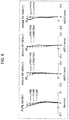
- a short dashed line illustrates a characteristic of the C-line.
- a long dashed line illustrates a characteristic of the F-line.
- a horizontal axis illustrates astigmatism, whereas a perpendicular axis illustrates angles of view.
- a solid line illustrates a characteristic of a YZ plane (in the diagram, y direction).
- a dashed line illustrates a characteristic of an XZ plane (in the diagram, x direction).
- Lens system 111 according to the first numerical value example corresponds to the first exemplary embodiment illustrated in FIG. 1 .
- Surface data of lens system 111 according to the first numerical value example is illustrated in Table 1.
- Various kinds of data is illustrated in Table 2.
- Aspherical and free-curved surface data of a fifth surface, a sixth surface, a ninth surface, a tenth surface, a fifteenth surface, and a sixteenth surface is illustrated in Table 3, Table 4, Table 5, Table 6, Table 7, and Table 8, respectively.
- Lens system 121 according to the second numerical value example corresponds to the second exemplary embodiment illustrated in FIG. 2 .
- Surface data of lens system 121 according to the second numerical value example is illustrated in Table 9.
- Various kinds of data is illustrated in Table 10.
- Aspherical and free-curved surface data of a fifth surface, a sixth surface, a ninth surface, a tenth surface, a fifteenth surface, and a sixteenth surface is illustrated in Table 11, Table 12, Table 13, Table 14, Table 15, and Table 16, respectively.
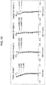
- FIG. 10 is a spherical aberration diagram and astigmatism diagrams in an infinity focusing state of lens system 131 according to a third numerical value example.
- FIG. 11 is a diagram illustrating a relationship between an angle of view and an image point in the infinity focusing state of lens system 131 according to the third numerical value example. Even in a case of lens system 131 illustrated in FIG. 11 , compared with a normal rotational symmetrical lens, it can be seen that a shape of the image surface is expanded, and the region of the photosensitive surface of imaging element 102 having a quadrilateral shape is effectively utilized.
- Lens system 131 according to the third numerical value example corresponds to the third exemplary embodiment illustrated in FIG. 3 .
- Surface data of lens system 131 according to the third numerical value example is illustrated in Table 17.
- Various kinds of data is illustrated in Table 18.
- Aspherical and free-curved surface data of a fifth surface, a sixth surface, a ninth surface, a tenth surface, a fifteenth surface, and a sixteenth surface is illustrated in Table 19, Table 20, Table 21, Table 22, Table 23, and Table 24, respectively.
- Table 25 described below illustrates corresponding values to the conditions in the lens systems according to the numerical value examples.
- the lens systems according to the implementations are applicable to digital still cameras, digital video cameras, cameras of cellular phones, cameras of personal digital assistances (PDAs), monitoring cameras of monitoring systems, Web cameras, and on-vehicle cameras, for example.
- the lens systems according to the implementations are preferable for photographing optical systems for which high image quality is required, such as digital still camera systems and digital video camera systems.
Landscapes
- Physics & Mathematics (AREA)
- General Physics & Mathematics (AREA)
- Optics & Photonics (AREA)
- Engineering & Computer Science (AREA)
- Multimedia (AREA)
- Signal Processing (AREA)
- Lenses (AREA)
- Stereoscopic And Panoramic Photography (AREA)
- Studio Devices (AREA)
Applications Claiming Priority (2)
| Application Number | Priority Date | Filing Date | Title |
|---|---|---|---|
| JP2017115547 | 2017-06-13 | ||
| PCT/JP2018/004775 WO2018230034A1 (ja) | 2017-06-13 | 2018-02-13 | レンズ系、カメラシステム及び撮像システム |
Publications (3)
| Publication Number | Publication Date |
|---|---|
| EP3640700A1 true EP3640700A1 (de) | 2020-04-22 |
| EP3640700A4 EP3640700A4 (de) | 2020-06-10 |
| EP3640700B1 EP3640700B1 (de) | 2024-12-25 |
Family
ID=64658622
Family Applications (1)
| Application Number | Title | Priority Date | Filing Date |
|---|---|---|---|
| EP18818135.8A Active EP3640700B1 (de) | 2017-06-13 | 2018-02-13 | Linsensystem, kamerasystem und abbildungssystem |
Country Status (6)
| Country | Link |
|---|---|
| US (1) | US11327278B2 (de) |
| EP (1) | EP3640700B1 (de) |
| JP (2) | JP6607426B2 (de) |
| KR (1) | KR20200017404A (de) |
| CN (1) | CN110730920B (de) |
| WO (1) | WO2018230034A1 (de) |
Families Citing this family (12)
| Publication number | Priority date | Publication date | Assignee | Title |
|---|---|---|---|---|
| JP7117605B2 (ja) * | 2017-06-13 | 2022-08-15 | パナソニックIpマネジメント株式会社 | レンズ系、カメラシステム及び撮像システム |
| JP6653456B1 (ja) | 2019-05-24 | 2020-02-26 | パナソニックIpマネジメント株式会社 | 撮像装置 |
| EP3994513A1 (de) * | 2019-07-31 | 2022-05-11 | Huawei Technologies Co., Ltd. | Bilderfassungslinsenanordnung, bilderfassungsvorrichtung und elektronische vorrichtung |
| CN110505384B (zh) * | 2019-08-29 | 2021-05-14 | Oppo广东移动通信有限公司 | 成像系统、终端和图像获取方法 |
| EP4040210A4 (de) | 2019-09-30 | 2022-12-07 | Panasonic Intellectual Property Management Co., Ltd. | Linsensystem, bildgebungsvorrichtung und bildgebungssystem |
| CN114503005B (zh) | 2019-09-30 | 2024-06-14 | 松下知识产权经营株式会社 | 透镜系统、摄像装置以及摄像系统 |
| CN111736311B (zh) * | 2020-07-27 | 2020-11-13 | 常州市瑞泰光电有限公司 | 摄像光学镜头 |
| KR102526441B1 (ko) | 2020-10-12 | 2023-04-27 | 삼성전기주식회사 | 촬상 광학계 |
| CN114384671B (zh) * | 2022-01-27 | 2023-10-20 | 杭州电子科技大学 | 广角变形摄像镜头 |
| KR20240035164A (ko) * | 2022-09-08 | 2024-03-15 | 엘지이노텍 주식회사 | 광학계 및 이를 포함하는 카메라 장치 |
| KR20240044749A (ko) * | 2022-09-29 | 2024-04-05 | 엘지이노텍 주식회사 | 광학계 및 이를 포함하는 카메라 장치 |
| WO2025023790A1 (ko) * | 2023-07-26 | 2025-01-30 | 삼성전자 주식회사 | 카메라 모듈 및 그를 포함하는 전자 장치 |
Family Cites Families (14)
| Publication number | Priority date | Publication date | Assignee | Title |
|---|---|---|---|---|
| JPS53127722A (en) * | 1977-04-13 | 1978-11-08 | Fuji Photo Film Co Ltd | Anamorphic lens |
| FR2827680B1 (fr) * | 2001-07-20 | 2003-10-10 | Immervision Internat Pte Ltd | Procede de capture d'une image panoramique au moyen d'un capteur d'image de forme rectangulaire |
| SE519974C2 (sv) | 2002-06-03 | 2003-05-06 | Cemvac System Ab | Anordning för utmatning av en monomer till en med en polymer förfylld blandningsanordning för tillredning av bencement |
| JP2006011093A (ja) * | 2004-06-25 | 2006-01-12 | Konica Minolta Opto Inc | 超広角光学系、撮像装置、車載カメラ及びデジタル機器 |
| JP4847150B2 (ja) * | 2005-02-21 | 2011-12-28 | 富士フイルム株式会社 | 広角撮像レンズ |
| JP4738845B2 (ja) * | 2005-03-01 | 2011-08-03 | 株式会社オートネットワーク技術研究所 | 車両周辺監視装置 |
| JP4790399B2 (ja) * | 2005-12-09 | 2011-10-12 | コニカミノルタオプト株式会社 | 超広角撮像光学系、超広角撮像レンズ装置及び撮像装置 |
| KR101428136B1 (ko) * | 2007-08-03 | 2014-08-07 | 칼 짜이스 에스엠티 게엠베하 | 마이크로리소그래피용 투사 대물렌즈, 투사 노광 장치, 투사 노광 방법 및 광학 보정 플레이트 |
| JP4669539B2 (ja) * | 2008-10-01 | 2011-04-13 | 株式会社トプコン | 撮像装置、車載カメラ及び監視カメラ |
| JP2010276755A (ja) | 2009-05-27 | 2010-12-09 | Konica Minolta Opto Inc | 超広角アナモルフィックレンズ |
| JP2016148725A (ja) * | 2015-02-10 | 2016-08-18 | 株式会社トヨテック | 広角レンズ及び広角レンズユニット |
| JP7117605B2 (ja) * | 2017-06-13 | 2022-08-15 | パナソニックIpマネジメント株式会社 | レンズ系、カメラシステム及び撮像システム |
| WO2018230035A1 (ja) * | 2017-06-13 | 2018-12-20 | パナソニックIpマネジメント株式会社 | レンズ系、カメラシステム及び撮像システム |
| JP7155678B2 (ja) * | 2018-07-06 | 2022-10-19 | マツダ株式会社 | ディーゼルエンジンの燃料噴射制御装置 |
-
2018
- 2018-02-13 EP EP18818135.8A patent/EP3640700B1/de active Active
- 2018-02-13 CN CN201880037456.1A patent/CN110730920B/zh active Active
- 2018-02-13 WO PCT/JP2018/004775 patent/WO2018230034A1/ja not_active Ceased
- 2018-02-13 KR KR1020197036342A patent/KR20200017404A/ko not_active Ceased
- 2018-02-13 JP JP2019525067A patent/JP6607426B2/ja active Active
-
2019
- 2019-10-09 JP JP2019186014A patent/JP7108934B2/ja active Active
- 2019-12-09 US US16/707,997 patent/US11327278B2/en active Active
Also Published As
| Publication number | Publication date |
|---|---|
| CN110730920A (zh) | 2020-01-24 |
| US20200116982A1 (en) | 2020-04-16 |
| JP2020024439A (ja) | 2020-02-13 |
| JP7108934B2 (ja) | 2022-07-29 |
| EP3640700A4 (de) | 2020-06-10 |
| KR20200017404A (ko) | 2020-02-18 |
| US11327278B2 (en) | 2022-05-10 |
| WO2018230034A1 (ja) | 2018-12-20 |
| JPWO2018230034A1 (ja) | 2019-11-21 |
| CN110730920B (zh) | 2022-05-10 |
| JP6607426B2 (ja) | 2019-11-20 |
| EP3640700B1 (de) | 2024-12-25 |
Similar Documents
| Publication | Publication Date | Title |
|---|---|---|
| US11327278B2 (en) | Lens system, camera system, and imaging system | |
| US11493732B2 (en) | Lens system, camera system, and imaging system | |
| US11493739B2 (en) | Lens system, camera system, and imaging system | |
| US10067314B2 (en) | Lens system and camera system including the lens system | |
| US20230228978A1 (en) | Optical imaging lens | |
| US9690080B2 (en) | Wide angle lens | |
| US9244251B2 (en) | Wide-angle photographic lens system enabling correction of distortion | |
| US20150085383A1 (en) | Wide-angle photographic lens system enabling correction of distortion | |
| US10976522B2 (en) | Imaging optical system | |
| CN106324797A (zh) | 光学镜头 | |
| EP3379316B1 (de) | Bildgebungslinse | |
| US9864166B2 (en) | Imaging lens and imaging apparatus | |
| JP6827173B2 (ja) | レンズ系および該レンズ系を含むカメラシステム | |
| US9841582B2 (en) | Imaging lens and imaging apparatus | |
| JP2021144151A (ja) | 撮像レンズ系及び撮像装置 | |
| US10215958B2 (en) | Optical imaging lens | |
| JP2017173818A (ja) | 撮像レンズ | |
| JP2005316208A (ja) | 撮像レンズ | |
| JP2007133324A (ja) | レンズユニット | |
| JP2005249983A (ja) | 広角レンズ | |
| JP2006308789A (ja) | 撮像レンズ | |
| JP2004085679A (ja) | 撮像用レンズ |
Legal Events
| Date | Code | Title | Description |
|---|---|---|---|
| STAA | Information on the status of an ep patent application or granted ep patent |
Free format text: STATUS: THE INTERNATIONAL PUBLICATION HAS BEEN MADE |
|
| PUAI | Public reference made under article 153(3) epc to a published international application that has entered the european phase |
Free format text: ORIGINAL CODE: 0009012 |
|
| STAA | Information on the status of an ep patent application or granted ep patent |
Free format text: STATUS: REQUEST FOR EXAMINATION WAS MADE |
|
| 17P | Request for examination filed |
Effective date: 20191212 |
|
| AK | Designated contracting states |
Kind code of ref document: A1 Designated state(s): AL AT BE BG CH CY CZ DE DK EE ES FI FR GB GR HR HU IE IS IT LI LT LU LV MC MK MT NL NO PL PT RO RS SE SI SK SM TR |
|
| AX | Request for extension of the european patent |
Extension state: BA ME |
|
| A4 | Supplementary search report drawn up and despatched |
Effective date: 20200512 |
|
| RIC1 | Information provided on ipc code assigned before grant |
Ipc: G02B 13/08 20060101ALI20200504BHEP Ipc: G02B 13/04 20060101AFI20200504BHEP Ipc: G02B 9/64 20060101ALI20200504BHEP Ipc: G02B 13/18 20060101ALI20200504BHEP Ipc: G02B 13/00 20060101ALI20200504BHEP |
|
| DAV | Request for validation of the european patent (deleted) | ||
| DAX | Request for extension of the european patent (deleted) | ||
| STAA | Information on the status of an ep patent application or granted ep patent |
Free format text: STATUS: EXAMINATION IS IN PROGRESS |
|
| 17Q | First examination report despatched |
Effective date: 20221109 |
|
| GRAP | Despatch of communication of intention to grant a patent |
Free format text: ORIGINAL CODE: EPIDOSNIGR1 |
|
| STAA | Information on the status of an ep patent application or granted ep patent |
Free format text: STATUS: GRANT OF PATENT IS INTENDED |
|
| INTG | Intention to grant announced |
Effective date: 20240802 |
|
| GRAS | Grant fee paid |
Free format text: ORIGINAL CODE: EPIDOSNIGR3 |
|
| GRAA | (expected) grant |
Free format text: ORIGINAL CODE: 0009210 |
|
| STAA | Information on the status of an ep patent application or granted ep patent |
Free format text: STATUS: THE PATENT HAS BEEN GRANTED |
|
| AK | Designated contracting states |
Kind code of ref document: B1 Designated state(s): AL AT BE BG CH CY CZ DE DK EE ES FI FR GB GR HR HU IE IS IT LI LT LU LV MC MK MT NL NO PL PT RO RS SE SI SK SM TR |
|
| REG | Reference to a national code |
Ref country code: GB Ref legal event code: FG4D |
|
| REG | Reference to a national code |
Ref country code: CH Ref legal event code: EP |
|
| REG | Reference to a national code |
Ref country code: DE Ref legal event code: R096 Ref document number: 602018077970 Country of ref document: DE |
|
| REG | Reference to a national code |
Ref country code: IE Ref legal event code: FG4D |
|
| REG | Reference to a national code |
Ref country code: LT Ref legal event code: MG9D |
|
| PG25 | Lapsed in a contracting state [announced via postgrant information from national office to epo] |
Ref country code: HR Free format text: LAPSE BECAUSE OF FAILURE TO SUBMIT A TRANSLATION OF THE DESCRIPTION OR TO PAY THE FEE WITHIN THE PRESCRIBED TIME-LIMIT Effective date: 20241225 |
|
| PG25 | Lapsed in a contracting state [announced via postgrant information from national office to epo] |
Ref country code: FI Free format text: LAPSE BECAUSE OF FAILURE TO SUBMIT A TRANSLATION OF THE DESCRIPTION OR TO PAY THE FEE WITHIN THE PRESCRIBED TIME-LIMIT Effective date: 20241225 |
|
| PG25 | Lapsed in a contracting state [announced via postgrant information from national office to epo] |
Ref country code: BG Free format text: LAPSE BECAUSE OF FAILURE TO SUBMIT A TRANSLATION OF THE DESCRIPTION OR TO PAY THE FEE WITHIN THE PRESCRIBED TIME-LIMIT Effective date: 20241225 |
|
| PG25 | Lapsed in a contracting state [announced via postgrant information from national office to epo] |
Ref country code: NO Free format text: LAPSE BECAUSE OF FAILURE TO SUBMIT A TRANSLATION OF THE DESCRIPTION OR TO PAY THE FEE WITHIN THE PRESCRIBED TIME-LIMIT Effective date: 20250325 |
|
| PG25 | Lapsed in a contracting state [announced via postgrant information from national office to epo] |
Ref country code: GR Free format text: LAPSE BECAUSE OF FAILURE TO SUBMIT A TRANSLATION OF THE DESCRIPTION OR TO PAY THE FEE WITHIN THE PRESCRIBED TIME-LIMIT Effective date: 20250326 Ref country code: LV Free format text: LAPSE BECAUSE OF FAILURE TO SUBMIT A TRANSLATION OF THE DESCRIPTION OR TO PAY THE FEE WITHIN THE PRESCRIBED TIME-LIMIT Effective date: 20241225 |
|
| PG25 | Lapsed in a contracting state [announced via postgrant information from national office to epo] |
Ref country code: RS Free format text: LAPSE BECAUSE OF FAILURE TO SUBMIT A TRANSLATION OF THE DESCRIPTION OR TO PAY THE FEE WITHIN THE PRESCRIBED TIME-LIMIT Effective date: 20250325 |
|
| REG | Reference to a national code |
Ref country code: NL Ref legal event code: MP Effective date: 20241225 |
|
| PG25 | Lapsed in a contracting state [announced via postgrant information from national office to epo] |
Ref country code: NL Free format text: LAPSE BECAUSE OF FAILURE TO SUBMIT A TRANSLATION OF THE DESCRIPTION OR TO PAY THE FEE WITHIN THE PRESCRIBED TIME-LIMIT Effective date: 20241225 |
|
| REG | Reference to a national code |
Ref country code: AT Ref legal event code: MK05 Ref document number: 1754653 Country of ref document: AT Kind code of ref document: T Effective date: 20241225 |
|
| PG25 | Lapsed in a contracting state [announced via postgrant information from national office to epo] |
Ref country code: SM Free format text: LAPSE BECAUSE OF FAILURE TO SUBMIT A TRANSLATION OF THE DESCRIPTION OR TO PAY THE FEE WITHIN THE PRESCRIBED TIME-LIMIT Effective date: 20241225 |
|
| PG25 | Lapsed in a contracting state [announced via postgrant information from national office to epo] |
Ref country code: PL Free format text: LAPSE BECAUSE OF FAILURE TO SUBMIT A TRANSLATION OF THE DESCRIPTION OR TO PAY THE FEE WITHIN THE PRESCRIBED TIME-LIMIT Effective date: 20241225 |
|
| PG25 | Lapsed in a contracting state [announced via postgrant information from national office to epo] |
Ref country code: ES Free format text: LAPSE BECAUSE OF FAILURE TO SUBMIT A TRANSLATION OF THE DESCRIPTION OR TO PAY THE FEE WITHIN THE PRESCRIBED TIME-LIMIT Effective date: 20241225 |
|
| PG25 | Lapsed in a contracting state [announced via postgrant information from national office to epo] |
Ref country code: IS Free format text: LAPSE BECAUSE OF FAILURE TO SUBMIT A TRANSLATION OF THE DESCRIPTION OR TO PAY THE FEE WITHIN THE PRESCRIBED TIME-LIMIT Effective date: 20250425 |
|
| PG25 | Lapsed in a contracting state [announced via postgrant information from national office to epo] |
Ref country code: PT Free format text: LAPSE BECAUSE OF FAILURE TO SUBMIT A TRANSLATION OF THE DESCRIPTION OR TO PAY THE FEE WITHIN THE PRESCRIBED TIME-LIMIT Effective date: 20250428 |
|
| PG25 | Lapsed in a contracting state [announced via postgrant information from national office to epo] |
Ref country code: EE Free format text: LAPSE BECAUSE OF FAILURE TO SUBMIT A TRANSLATION OF THE DESCRIPTION OR TO PAY THE FEE WITHIN THE PRESCRIBED TIME-LIMIT Effective date: 20241225 |
|
| PG25 | Lapsed in a contracting state [announced via postgrant information from national office to epo] |
Ref country code: AT Free format text: LAPSE BECAUSE OF FAILURE TO SUBMIT A TRANSLATION OF THE DESCRIPTION OR TO PAY THE FEE WITHIN THE PRESCRIBED TIME-LIMIT Effective date: 20241225 Ref country code: RO Free format text: LAPSE BECAUSE OF FAILURE TO SUBMIT A TRANSLATION OF THE DESCRIPTION OR TO PAY THE FEE WITHIN THE PRESCRIBED TIME-LIMIT Effective date: 20241225 |
|
| PG25 | Lapsed in a contracting state [announced via postgrant information from national office to epo] |
Ref country code: SK Free format text: LAPSE BECAUSE OF FAILURE TO SUBMIT A TRANSLATION OF THE DESCRIPTION OR TO PAY THE FEE WITHIN THE PRESCRIBED TIME-LIMIT Effective date: 20241225 |
|
| PG25 | Lapsed in a contracting state [announced via postgrant information from national office to epo] |
Ref country code: CZ Free format text: LAPSE BECAUSE OF FAILURE TO SUBMIT A TRANSLATION OF THE DESCRIPTION OR TO PAY THE FEE WITHIN THE PRESCRIBED TIME-LIMIT Effective date: 20241225 |
|
| PG25 | Lapsed in a contracting state [announced via postgrant information from national office to epo] |
Ref country code: IT Free format text: LAPSE BECAUSE OF FAILURE TO SUBMIT A TRANSLATION OF THE DESCRIPTION OR TO PAY THE FEE WITHIN THE PRESCRIBED TIME-LIMIT Effective date: 20241225 |
|
| PG25 | Lapsed in a contracting state [announced via postgrant information from national office to epo] |
Ref country code: SE Free format text: LAPSE BECAUSE OF FAILURE TO SUBMIT A TRANSLATION OF THE DESCRIPTION OR TO PAY THE FEE WITHIN THE PRESCRIBED TIME-LIMIT Effective date: 20241225 |
|
| PG25 | Lapsed in a contracting state [announced via postgrant information from national office to epo] |
Ref country code: MC Free format text: LAPSE BECAUSE OF FAILURE TO SUBMIT A TRANSLATION OF THE DESCRIPTION OR TO PAY THE FEE WITHIN THE PRESCRIBED TIME-LIMIT Effective date: 20241225 |
|
| REG | Reference to a national code |
Ref country code: DE Ref legal event code: R097 Ref document number: 602018077970 Country of ref document: DE |
|
| REG | Reference to a national code |
Ref country code: CH Ref legal event code: PL |
|
| PG25 | Lapsed in a contracting state [announced via postgrant information from national office to epo] |
Ref country code: DK Free format text: LAPSE BECAUSE OF FAILURE TO SUBMIT A TRANSLATION OF THE DESCRIPTION OR TO PAY THE FEE WITHIN THE PRESCRIBED TIME-LIMIT Effective date: 20241225 |
|
| PG25 | Lapsed in a contracting state [announced via postgrant information from national office to epo] |
Ref country code: LU Free format text: LAPSE BECAUSE OF NON-PAYMENT OF DUE FEES Effective date: 20250213 |
|
| PG25 | Lapsed in a contracting state [announced via postgrant information from national office to epo] |
Ref country code: CH Free format text: LAPSE BECAUSE OF NON-PAYMENT OF DUE FEES Effective date: 20250228 |
|
| PLBE | No opposition filed within time limit |
Free format text: ORIGINAL CODE: 0009261 |
|
| STAA | Information on the status of an ep patent application or granted ep patent |
Free format text: STATUS: NO OPPOSITION FILED WITHIN TIME LIMIT |
|
| GBPC | Gb: european patent ceased through non-payment of renewal fee |
Effective date: 20250325 |
|
| 26N | No opposition filed |
Effective date: 20250926 |
|
| REG | Reference to a national code |
Ref country code: BE Ref legal event code: MM Effective date: 20250228 |
|
| PG25 | Lapsed in a contracting state [announced via postgrant information from national office to epo] |
Ref country code: GB Free format text: LAPSE BECAUSE OF NON-PAYMENT OF DUE FEES Effective date: 20250325 |
|
| PG25 | Lapsed in a contracting state [announced via postgrant information from national office to epo] |
Ref country code: FR Free format text: LAPSE BECAUSE OF NON-PAYMENT OF DUE FEES Effective date: 20250225 |
|
| PG25 | Lapsed in a contracting state [announced via postgrant information from national office to epo] |
Ref country code: BE Free format text: LAPSE BECAUSE OF NON-PAYMENT OF DUE FEES Effective date: 20250228 |
|
| PG25 | Lapsed in a contracting state [announced via postgrant information from national office to epo] |
Ref country code: IE Free format text: LAPSE BECAUSE OF NON-PAYMENT OF DUE FEES Effective date: 20250213 |
|
| PGFP | Annual fee paid to national office [announced via postgrant information from national office to epo] |
Ref country code: DE Payment date: 20260218 Year of fee payment: 9 |