EP3640743A1 - Beobachtungsverfahren einer probe - Google Patents
Beobachtungsverfahren einer probe Download PDFInfo
- Publication number
- EP3640743A1 EP3640743A1 EP19203484.1A EP19203484A EP3640743A1 EP 3640743 A1 EP3640743 A1 EP 3640743A1 EP 19203484 A EP19203484 A EP 19203484A EP 3640743 A1 EP3640743 A1 EP 3640743A1
- Authority
- EP
- European Patent Office
- Prior art keywords
- sample
- image
- parameter
- plane
- during step
- Prior art date
- Legal status (The legal status is an assumption and is not a legal conclusion. Google has not performed a legal analysis and makes no representation as to the accuracy of the status listed.)
- Granted
Links
Images



Classifications
-
- G—PHYSICS
- G01—MEASURING; TESTING
- G01N—INVESTIGATING OR ANALYSING MATERIALS BY DETERMINING THEIR CHEMICAL OR PHYSICAL PROPERTIES
- G01N33/00—Investigating or analysing materials by specific methods not covered by groups G01N1/00 - G01N31/00
- G01N33/48—Biological material, e.g. blood, urine; Haemocytometers
- G01N33/483—Physical analysis of biological material
- G01N33/4833—Physical analysis of biological material of solid biological material, e.g. tissue samples, cell cultures
-
- G—PHYSICS
- G01—MEASURING; TESTING
- G01N—INVESTIGATING OR ANALYSING MATERIALS BY DETERMINING THEIR CHEMICAL OR PHYSICAL PROPERTIES
- G01N15/00—Investigating characteristics of particles; Investigating permeability, pore-volume or surface-area of porous materials
- G01N15/10—Investigating individual particles
- G01N15/14—Optical investigation techniques, e.g. flow cytometry
- G01N15/1429—Signal processing
- G01N15/1433—Signal processing using image recognition
-
- G—PHYSICS
- G01—MEASURING; TESTING
- G01N—INVESTIGATING OR ANALYSING MATERIALS BY DETERMINING THEIR CHEMICAL OR PHYSICAL PROPERTIES
- G01N15/00—Investigating characteristics of particles; Investigating permeability, pore-volume or surface-area of porous materials
- G01N15/10—Investigating individual particles
- G01N15/14—Optical investigation techniques, e.g. flow cytometry
- G01N15/1434—Optical arrangements
-
- G—PHYSICS
- G03—PHOTOGRAPHY; CINEMATOGRAPHY; ANALOGOUS TECHNIQUES USING WAVES OTHER THAN OPTICAL WAVES; ELECTROGRAPHY; HOLOGRAPHY
- G03H—HOLOGRAPHIC PROCESSES OR APPARATUS
- G03H1/00—Holographic processes or apparatus using light, infrared or ultraviolet waves for obtaining holograms or for obtaining an image from them; Details peculiar thereto
- G03H1/04—Processes or apparatus for producing holograms
- G03H1/0443—Digital holography, i.e. recording holograms with digital recording means
-
- G—PHYSICS
- G03—PHOTOGRAPHY; CINEMATOGRAPHY; ANALOGOUS TECHNIQUES USING WAVES OTHER THAN OPTICAL WAVES; ELECTROGRAPHY; HOLOGRAPHY
- G03H—HOLOGRAPHIC PROCESSES OR APPARATUS
- G03H1/00—Holographic processes or apparatus using light, infrared or ultraviolet waves for obtaining holograms or for obtaining an image from them; Details peculiar thereto
- G03H1/04—Processes or apparatus for producing holograms
- G03H1/08—Synthesising holograms, i.e. holograms synthesized from objects or objects from holograms
- G03H1/0866—Digital holographic imaging, i.e. synthesizing holobjects from holograms
-
- G—PHYSICS
- G01—MEASURING; TESTING
- G01N—INVESTIGATING OR ANALYSING MATERIALS BY DETERMINING THEIR CHEMICAL OR PHYSICAL PROPERTIES
- G01N15/00—Investigating characteristics of particles; Investigating permeability, pore-volume or surface-area of porous materials
- G01N15/10—Investigating individual particles
- G01N15/14—Optical investigation techniques, e.g. flow cytometry
- G01N15/1434—Optical arrangements
- G01N2015/1454—Optical arrangements using phase shift or interference, e.g. for improving contrast
-
- G—PHYSICS
- G01—MEASURING; TESTING
- G01N—INVESTIGATING OR ANALYSING MATERIALS BY DETERMINING THEIR CHEMICAL OR PHYSICAL PROPERTIES
- G01N2201/00—Features of devices classified in G01N21/00
- G01N2201/12—Circuits of general importance; Signal processing
-
- G—PHYSICS
- G03—PHOTOGRAPHY; CINEMATOGRAPHY; ANALOGOUS TECHNIQUES USING WAVES OTHER THAN OPTICAL WAVES; ELECTROGRAPHY; HOLOGRAPHY
- G03H—HOLOGRAPHIC PROCESSES OR APPARATUS
- G03H1/00—Holographic processes or apparatus using light, infrared or ultraviolet waves for obtaining holograms or for obtaining an image from them; Details peculiar thereto
- G03H1/0005—Adaptation of holography to specific applications
- G03H2001/0033—Adaptation of holography to specific applications in hologrammetry for measuring or analysing
-
- G—PHYSICS
- G03—PHOTOGRAPHY; CINEMATOGRAPHY; ANALOGOUS TECHNIQUES USING WAVES OTHER THAN OPTICAL WAVES; ELECTROGRAPHY; HOLOGRAPHY
- G03H—HOLOGRAPHIC PROCESSES OR APPARATUS
- G03H1/00—Holographic processes or apparatus using light, infrared or ultraviolet waves for obtaining holograms or for obtaining an image from them; Details peculiar thereto
- G03H1/04—Processes or apparatus for producing holograms
- G03H1/0443—Digital holography, i.e. recording holograms with digital recording means
- G03H2001/0447—In-line recording arrangement
-
- G—PHYSICS
- G03—PHOTOGRAPHY; CINEMATOGRAPHY; ANALOGOUS TECHNIQUES USING WAVES OTHER THAN OPTICAL WAVES; ELECTROGRAPHY; HOLOGRAPHY
- G03H—HOLOGRAPHIC PROCESSES OR APPARATUS
- G03H1/00—Holographic processes or apparatus using light, infrared or ultraviolet waves for obtaining holograms or for obtaining an image from them; Details peculiar thereto
- G03H1/04—Processes or apparatus for producing holograms
- G03H1/0443—Digital holography, i.e. recording holograms with digital recording means
- G03H2001/0452—Digital holography, i.e. recording holograms with digital recording means arranged to record an image of the object
-
- G—PHYSICS
- G03—PHOTOGRAPHY; CINEMATOGRAPHY; ANALOGOUS TECHNIQUES USING WAVES OTHER THAN OPTICAL WAVES; ELECTROGRAPHY; HOLOGRAPHY
- G03H—HOLOGRAPHIC PROCESSES OR APPARATUS
- G03H1/00—Holographic processes or apparatus using light, infrared or ultraviolet waves for obtaining holograms or for obtaining an image from them; Details peculiar thereto
- G03H1/04—Processes or apparatus for producing holograms
- G03H1/0465—Particular recording light; Beam shape or geometry
- G03H2001/0471—Object light being transmitted through the object, e.g. illumination through living cells
-
- G—PHYSICS
- G03—PHOTOGRAPHY; CINEMATOGRAPHY; ANALOGOUS TECHNIQUES USING WAVES OTHER THAN OPTICAL WAVES; ELECTROGRAPHY; HOLOGRAPHY
- G03H—HOLOGRAPHIC PROCESSES OR APPARATUS
- G03H1/00—Holographic processes or apparatus using light, infrared or ultraviolet waves for obtaining holograms or for obtaining an image from them; Details peculiar thereto
- G03H1/04—Processes or apparatus for producing holograms
- G03H1/08—Synthesising holograms, i.e. holograms synthesized from objects or objects from holograms
- G03H1/0808—Methods of numerical synthesis, e.g. coherent ray tracing [CRT], diffraction specific
- G03H2001/0816—Iterative algorithms
-
- G—PHYSICS
- G03—PHOTOGRAPHY; CINEMATOGRAPHY; ANALOGOUS TECHNIQUES USING WAVES OTHER THAN OPTICAL WAVES; ELECTROGRAPHY; HOLOGRAPHY
- G03H—HOLOGRAPHIC PROCESSES OR APPARATUS
- G03H2222/00—Light sources or light beam properties
- G03H2222/10—Spectral composition
- G03H2222/17—White light
- G03H2222/18—RGB trichrome light
Definitions
- the technical field of the invention is linked to the observation of a sample, in particular a biological sample, by lensless imaging, by implementing a holographic reconstruction algorithm with improved performance.
- This image is made up of interference figures between the light wave emitted by the light source and transmitted by the sample, and diffraction waves, resulting from the diffraction by the sample of the light wave emitted by the source. from light.
- interference figures are sometimes called diffraction figures, or designated by the English term "diffraction pattern".
- the document WO2008090330 describes a device allowing the observation of biological samples, in this case cells, by lensless imaging.
- the device makes it possible to associate, with each cell, an interference pattern whose morphology makes it possible to identify the type of cell.
- Lensless imaging then appears as a simple, inexpensive alternative to a conventional microscope.
- its field of observation is much larger than that of a microscope. We then understand that the application prospects linked to this technology are important.
- the image formed on the image sensor can be processed by a holographic reconstruction algorithm, so as to estimate the optical properties of the sample, for example a factor transmission or phase.
- a holographic reconstruction algorithm is well known in the field of holographic reconstruction.
- the reconstructed image can, in particular, be a complex image of the light wave transmitted by the sample, comprising information on the optical absorption or phase variation properties of the sample.
- holographic reconstruction algorithms can induce reconstruction noise in the reconstructed image, designated by the term of “twin image”.
- the holographic reconstruction is carried out on the basis of partial optical information, based solely on the intensity of the light wave collected on the image sensor.
- phase retrieval The improvement of the quality of the holographic reconstruction is the subject of numerous developments, by implementing algorithms frequently called "phase retrieval", allowing an estimation of the phase of the light wave to which the image sensor is exposed. .
- a digital reconstruction algorithm is for example described in US2012 / 0218379 . Reconstruction algorithms have also been described in WO2016189257 or in WO2017162985 .
- the inventors propose a method of observing a sample by a holographic imaging method, the method comprising a step of reconstruction of a complex image of the sample, on the basis of which a spatial representation of parameters can be obtained of the sample.
- Step v) can comprise a determination of a gradient of the validity indicator as a function of at least one parameter, so that the parameter vectors are updated to reduce the validity indicator of the next iteration.
- Step v) can implement a gradient descent type algorithm.
- the validity indicator can be a sum, possibly weighted, of the error criterion and the morphological criterion. According to one embodiment, the validity indicator is a weighted sum of the error criterion and the morphological criterion, the weight varying between at least two successive iterations.
- the calculation of the image in the detection plane may in particular include an application of a convolution product by a convolution nucleus, the convolution nucleus representing a spatial extent of the light source.
- the calculation of the image in the detection plane may include an integral of an elementary image, defined in an elementary spectral band, the integral being calculated to take account of a spectral band d emission of the light source.
- the emission spectral band is then formed by a juxtaposition of different elementary spectral bands. In other words, each elementary spectral band forms the spectral band.
- the figure 1A shows an example of a device according to the invention.
- a light source 11 is capable of emitting a light wave 12, called the incident light wave, propagating in the direction of a sample 10, along a propagation axis Z.
- the light wave is emitted according to a spectral band ⁇ , comprising a wavelength ⁇ . This wavelength can be a central wavelength of said spectral band.
- the light source 11 comprises elementary light sources 11 j .
- the index j denotes the index of the elementary light source.
- Each light source emits a light wave, along the propagation axis Z, in a spectral band ⁇ ⁇ j .
- the elementary sources emit in different spectral bands from each other, for example in blue, in green and in red. The use of such a light source has been described in WO2016189257 .
- Sample 10 is a sample that we wish to characterize. It can in particular be a 10m medium comprising 10p particles.
- the 10p particles can be blood particles, for example red blood cells. It can also be cells, microorganisms, for example bacteria or yeasts, microalgae, microbeads, or droplets insoluble in the liquid medium, for example lipid nanoparticles.
- the particles 10p have a diameter, or are inscribed in a diameter, less than 1 mm, and preferably less than 100 ⁇ m. These are microparticles (diameter less than 1 mm) or nanoparticles (diameter less than 1 ⁇ m).
- the medium 10m in which the particles are immersed, can be a liquid medium, for example a liquid phase of a body liquid, a culture medium or a liquid taken from the environment or in an industrial process. It can also be a solid medium or having the consistency of a gel, for example an agar-type substrate, suitable for the growth of bacterial colonies.
- the sample can also be a solid sample, for example a thin strip of biological tissue, of the pathology slide type, or a dry extract of a fluid, for example of a biological fluid.
- the sample is preferably transparent or sufficiently translucent to be able to allow the formation of an image by the image sensor.
- the sample 10 is contained in a fluid chamber 15.
- the fluid chamber 15 is for example a micro-cuvette, of current use in point of care type devices, into which the sample 10 penetrates, by example by capillarity.
- the thickness e of the sample 10, along the propagation axis typically varies between 20 ⁇ m and 1 cm, and is preferably between 50 ⁇ m and 500 ⁇ m, for example 150 ⁇ m.
- the sample extends along a plane P 10 , called the plane of the sample, perpendicular to the axis of propagation. It is held on a 10s support.
- the plane of the sample is identified by two orthogonal axes X and Y, defining x and y coordinates respectively. Each pair of coordinates ( x, y ) corresponds to a radial coordinate r.
- the radial coordinates are defined in the sample plane and in a detection plane described below.
- the distance D between the light source 11 and the sample 10 is preferably greater than 1 cm. It is preferably between 2 and 30 cm.
- the light source, seen by the sample is considered as a point. This means that its diameter (or its diagonal) is preferably less than a tenth, better a hundredth of the distance between the sample and the light source.
- the light reaches the sample in the form of plane waves, or which can be considered as such.
- the light source 11 can be a light emitting diode or a laser diode. It can be associated with diaphragm 18, or spatial filter.
- the diaphragm opening is typically between 5 ⁇ m and 1 mm, preferably between 50 ⁇ m and 500 ⁇ m.
- the diaphragm is supplied by Thorlabs under the reference P150S and its diameter is 150 ⁇ m.
- the diaphragm can be replaced by an optical fiber, a first end of which is placed facing the light source 11 and a second end of which is placed facing the sample 10.
- the device preferably comprises a diffuser 17, disposed between the light source 11 and the diaphragm 18.
- a diffuser 17 makes it possible to overcome constraints of centering of the light source 11 relative to the opening of the diaphragm 18.
- the function of such a diffuser is to distribute the light beam produced by the elementary light source 11 according to a cone of angle ⁇ , ⁇ being equal to 30 ° in the present case.
- the angle of diffusion ⁇ varies between 10 ° and 80 °.
- the emission spectral band ⁇ of the incident light wave 12 has a width less than 100 nm.
- spectral bandwidth is meant a width at half height of said spectral band.
- each spectral band is designated by a wavelength ⁇ representative of the spectral band, for example the central wavelength.
- the sample 10 is disposed between the light source 11 and an image sensor 16.
- the latter preferably extends parallel, or substantially parallel to the plane along which the sample extends.
- substantially parallel means that the two elements may not be strictly parallel, an angular tolerance of a few degrees, less than 20 ° or 10 ° being allowed.
- the image sensor 16 is able to form an image according to a detection plane P 0 .
- it is an image sensor comprising a pixel matrix, of CCD type or a CMOS.
- CMOS are the preferred sensors because the size of the pixels is smaller, which makes it possible to acquire images whose spatial resolution is more favorable.
- the detection plane P 0 preferably extends perpendicular to the axis of propagation Z of the incident light wave 12. Thus, the detection plane P 0 is parallel to the plane of the sample P 10 .
- the image sensor comprises pixels, with each pixel being associated with a radial coordinate r.
- the distance d between the sample 10 and the pixel matrix of the image sensor 16 is preferably between 50 ⁇ m and 2 cm, preferably between 100 ⁇ m and 2 mm.
- the sample 10 can generate a diffracted wave, capable of producing, at the level of the detection plane P 0 , interference, in particular with part of the incident light wave 12 transmitted by the sample. Furthermore, the sample can absorb part of the incident light wave 12.
- the light wave 14, transmitted by the sample, and to which the image sensor 16 is exposed is formed following the absorption and diffraction of the incident light wave 12 by the sample.
- the sample causes absorption of part of the incident light wave, as well as a phase shift of the latter.
- the phase shift is due to a variation in the refractive index (or optical index) when the light wave 14 propagates through the sample.
- the light wave 14 can also be designated by the term exposure light wave.
- a processor 20, for example a microprocessor, is able to process each image acquired by the image sensor 16.
- the processor is a microprocessor connected to a programmable memory 22 in which is stored a sequence of instructions for performing the image processing and calculation operations described in this description.
- the processor can be coupled to a screen 24 allowing the display of images acquired by the image sensor 16 or calculated by the processor 20.
- the image acquired by the image sensor forms a hologram. It generally does not allow a satisfactory visual representation of the sample, in particular when the sample comprises diffracting elements close to each other. This is particularly the case when the sample contains particles close to each other, or when the sample is a thin section of biological tissue.
- iterative image reconstruction algorithms have been developed, such as those described in the prior art. These algorithms include an iterative application of a holographic propagation operator, so as to propagate the hologram, formed in the detection plane, in a reconstruction plane, the latter generally corresponding to a plane of the sample, according to which s extends the sample.
- the plane of the sample is generally parallel to the plane of detection.
- the algorithms described in the prior art include successions of propagation / backpropagation, of images between the detection plane and the plane of the sample.
- the image acquired by the image sensor does not include information relating to the phase of the exposure light wave.
- the objective of these algorithms is to estimate, iteratively, the phase of the exposure light wave in the detection plane. This makes it possible to form a correct image of the sample, in the reconstruction plan.
- these algorithms make it possible to obtain optical properties of the exposure light wave 14. It can be, for example, the module or the phase.
- the approach proposed by the inventor is different, since it aims not to obtain properties of the exposure light wave 14, but properties of the sample itself, and in particular optical properties of the latter.
- the sample is described by vectors F ( r ), each vector being defined at a radial coordinate r in the plane of the sample.
- Each term of each vector corresponds to an optical property of the sample.
- the radial coordinates r ( x, y ), defined in the sample plan.
- the vector of parameters F ( r ) has a dimension (1, N w ) , where N w denotes the number of parameters considered.
- Each component of the parameter vector is an optical parameter of the sample.
- a component of the vector is a difference in optical path L ( r ) induced by the sample in a direction parallel to the propagation axis Z.
- the figure 2 shows a detail of a 10 p particle of the sample.
- the 10 p particle is an adherent cell. It adheres to a transparent wall of the fluid chamber 15.
- the particle 10 p has a refractive index n p
- the medium 10 m in which it bathes has a refractive index n m .
- the wavefront of the light wave 12, incident on the sample, as well as of the exposure light wave 14, to which the image sensor 16 is exposed has been represented by dotted lines, the exposure light wave propagating from the sample to the image sensor.
- the wavefront is flat before reaching the sample. Downstream of the sample, the wavefront is distorted due to the appearance of optical path differences induced by the particle.
- Another component of the vector F ( r ) can be an absorbance ⁇ ( r ) of the sample.
- the optical path and / or the absorbance can be expressed in each wavelength ⁇ .
- the difference in optical path L ( r ) depends on the emission spectral band, in which case it is denoted L ⁇ ( r ) .
- an adjustment variable is defined, defining a phase jump. Indeed, the phase of a light wave is defined modulo 2 ⁇ .
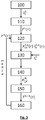
- Step 100 Acquisition of an image I 0 ⁇ in each spectral band ⁇ ⁇ .
- Step 110 Initialization of the vector of parameters F ( r ).
- the terms composing the initial vector are defined arbitrarily or according to an a priori on the sample. This step is performed for each radial coordinate r considered.
- the vectors of parameters F ( r ) defined during this step form a set of vectors describing the sample 10. Each initialized vector is noted F 1 ( r ).
- Each stage is associated with a set of vectors F n ( r ).
- Step 120 For each radial coordinate r, from the vector of parameters resulting from step 110, or from step 150 of a previous iteration, determination of a complex amplitude AT 10 ⁇ , not r of the exposure light wave 14, in the plane of the sample.
- the complex amplitude can for example be determined from one of the expressions (1) to (5).
- Each complex amplitude AT 10 ⁇ , not r form to a complex image AT 10 ⁇ , not of the sample.
- the holographic propagation operator models a transport of the light exposure wave between at least two points distant from each other.
- the convolution product described in connection with equation (6) models a transport of the exposure light wave 14 between the plane of the sample P 10 and the detection plane P 0 .
- Step 120 is implemented in each spectral band.
- Step 130 In each spectral band, comparison of the image I ⁇ 0 ⁇ estimated in step 120 with the image I 0 ⁇ acquired by the image sensor during step 100.
- the comparison can be expressed in the form of a difference or of a ratio, or of a quadratic deviation.
- Step 140 Calculation of a validity indicator from the comparison made, during step 130, in each spectral band.
- F not not represents the relevance of the whole vectors F n ( r ) describing the sample.
- the index means that the validity indicator is established knowing the set vectors F n ( r ). In this example, the validity indicator is lower when the sample is correctly described by the group .
- F not not includes an error criterion ⁇ 0
- global error is meant an error for each radial coordinate and for each spectral band considered.
- F not not represents the fact that this indicator is calculated in the detection plan, knowing all the vectors taken into account during the iteration.
- F not not is a data attachment criterion, in the sense that its minimization makes it possible to approximate the measured data, in this case each image I 0 ⁇ .
- I ⁇ 0 ⁇ not tends to I 0 ⁇ , that is to say when the whole vectors correctly describe the sample 10, ⁇ 0
- the term I 0 ⁇ r - I ⁇ 0 ⁇ , not r ⁇ I 0 ⁇ , not r 2 tends to 1.
- F not not ⁇ 0
- F not not the validity indicator only takes into account the error criterion.
- the validity indicator also includes a morphological criterion, corresponding to the taking into account of geometric or optical constraints of the sample or of the particles forming the sample.
- Step 150 Updating the vectors F n ( r ) by minimizing the validity indicator ⁇
- F not not is a scalar variable. However, it depends on the whole parameter vectors on the basis of which it was established, via the image I ⁇ 0 ⁇ , not estimated in each spectral band considered.
- step 150 a minimization algorithm is applied, of the gradient descent type, so as to approach progressively, at each iteration, the set allowing a satisfactory minimization of the validity indicator ⁇
- the objective of this step is to establish a set F not + 1 vectors F not + 1 r aiming to obtain, following a reiteration of steps 110 to 140, a validity indicator ⁇
- This step updates at least one term F w not r of each vector F n ( r ).
- a gradient descent algorithm then defines a direction d w not as well as a step forward ⁇ w not .
- the gradient G w not r can be defined for each term F w not r vectors F n ( r ).
- Step 160 repetition of steps 120 to 150, taking into account, during step 120 of the following iteration, the set F not + 1 updated during step 150 of the iteration last performed.
- Steps 120 to 160 are repeated until the value of the validity indicator ⁇
- the iterations stop when the value of the validity indicator ⁇
- F not not also takes into account a morphological criterion ⁇ 10
- F not not is defined in the plane of the sample P 10 .
- F not depends on the value of the terms of the parameter vectors determined during step 110 or during step 150 of a previous iteration, or their spatial derivatives. It is representative of the morphology of the sample, as determined from the parameter vectors.
- the morphological criterion represents a criterion of attachment to the morphological data of the sample, the latter being able to be defined by hypotheses.
- F not not can take into account a spatial derivative of the optical path difference, so as to take into account a predefined shape of a particle.
- the predefined shape can be a hemisphere, such a case being represented on the figure 2 .
- the predefined shape can be a sphere when the cells are spherical.
- the morphological criterion is therefore, in its most general form, a weighted sum of operators which is applied to different terms of each vector F n ( r ). This weighted sum is integrated according to the different radial coordinates considered, so as to form a morphological indicator ⁇ 10
- each parameter vector comprises a term L n ( r )
- L n ( r ) an example of morphological criterion is: ⁇ 10
- F not not ⁇ dr ⁇ L not r ⁇ x 2 + ⁇ L not r ⁇ y 2
- This criterion tends to decrease when the quantity L n ( r ) does not present a minimum of oscillations, which is for example the case when the particles have a spherical or hemispherical morphology of particles.
- the values of L n ( r ) for which the criterion is minimal therefore correspond to particles, for example spherical or hemispherical, isolated from each other, with a minimum of oscillation of L n ( r ) between the particles or on these past.
- F not not is minimal when the vectors of parameters F n ( r ) forming the set describe objects that meet a priori morphological hypotheses.
- F not includes consideration of the morphological criterion ⁇ 10
- the expression of the validity indicator can then be, for example: ⁇
- F not not ⁇ 0
- B ⁇ ( r ) is determined when the image sensor is exposed to an illumination of the light source without a sample placed between the light source and the image sensor.
- the iterations stop.
- the sample is then considered to be correctly represented by the vectors F n ( r ) forming the set . Iterations can also stop when a predetermined number of iterations is reached.
- the value of the scalar ⁇ varies according to the iterations.
- a validity indicator is calculated such that: ⁇
- F not not ⁇ 0
- ⁇ n is zero or close to zero.
- the validity indicator then favors attachment to the data, through the error criterion ⁇ 0
- the value of the weighting term ⁇ n increases, so as to take more account of the morphological criterion ⁇ 10
- F not not is only calculated from the error criterion ⁇ 0
- the vectors F n ( r ) describing the sample 10 evolve. For example, during the first iterations of steps 120 to 160, the difference in optical path is considered to be independent of the wavelength. Each vector F n ( r ) therefore comprises a term L n ( r ) corresponding to the difference in optical path. In a second step, for example when the term L n ( r ) does not change significantly between two successive iterations, or after a predetermined number of iterations, each vector F n ( r ) has as many terms L ⁇ , n ( r ) only of emission spectral bands, these terms being independent of each other. This refines the model of the sample.
- step 120 account is taken of imperfections in the light source. It is for example possible to take into account the size of the source. It is a question of considering the fact that the source is not perfectly punctual.
- the spectral width of each emission spectral band ⁇ ⁇ is taken into account.
- the image I ⁇ 0 ⁇ not is defined by taking into account an emission rate s ( d ⁇ ) in an elementary spectral band d ⁇ .
- the elementary spectral band d ⁇ corresponds to the step of discretization of the spectral band considered.
- I ⁇ 0 ⁇ , not ⁇ d ⁇ s d ⁇ AT 0 ⁇ + d ⁇ , not ⁇ h P 10 ⁇ P 0 ⁇ + d ⁇
- An example was made using a sample comprising A549 type cells placed in a sample comprising a liquid culture medium, at a distance of 1400 ⁇ m from a CMOS type image sensor: pixel size: 1.67 ⁇ m x 1.67 ⁇ m - 10 million pixels.
- the light source included 3 light emitting diodes emitting in red, green and blue respectively.
- the light source was placed at a distance of 50 mm from the sample. It was coupled to a diaphragm defining an opening with a diameter of 50 ⁇ m.
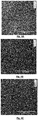
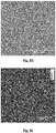
- the Figures 4A, 4B and 4C show the images acquired respectively in the red, green and blue spectral bands.
- the figure 4D shows an image of the gradient G w not r of the validity indicator ⁇
- F not not established for each pixel r, as a function of the parameter L ( r ) during the first iteration ( n 1).
- the validity indicator is such that: ⁇
- F not not ⁇ 0
- F not not 4 NOT r NOT ⁇ ⁇ dr ⁇ ⁇ M ⁇ 0 ⁇ , not - M 0 ⁇ 2 and ⁇ 10
- F not not ⁇ dr ⁇ L not r ⁇ x 2 + ⁇ L not r ⁇ y 2 + L not r 2
- the figure 5 schematizes a device allowing an implementation of the invention.
- the device of the figure 5 comprises an optical system 19 for image formation.
- the optical system 19 defines an image plane and an object plane.
- the optical system can be a lens or objective.
- the image sensor When acquiring the image of the sample, the image sensor is arranged in a defocused configuration.
- the detection plane is offset from the image plane and / or the plane along which the sample extends is offset from the object plane.
- the offset is generally small, preferably being less than 1 mm, and typically in the range 50 ⁇ m - 500 ⁇ m.
- the invention may be implemented for the observation of samples in the field of biology or health, in the field of environmental control or in other industrial fields, including the food industry.
Landscapes
- Physics & Mathematics (AREA)
- Health & Medical Sciences (AREA)
- Engineering & Computer Science (AREA)
- Life Sciences & Earth Sciences (AREA)
- Chemical & Material Sciences (AREA)
- General Physics & Mathematics (AREA)
- Biomedical Technology (AREA)
- Analytical Chemistry (AREA)
- Biochemistry (AREA)
- General Health & Medical Sciences (AREA)
- Immunology (AREA)
- Pathology (AREA)
- Computing Systems (AREA)
- Theoretical Computer Science (AREA)
- Dispersion Chemistry (AREA)
- Optics & Photonics (AREA)
- Biophysics (AREA)
- Hematology (AREA)
- Molecular Biology (AREA)
- Urology & Nephrology (AREA)
- Food Science & Technology (AREA)
- Medicinal Chemistry (AREA)
- Signal Processing (AREA)
- Investigating Or Analysing Materials By Optical Means (AREA)
- Microscoopes, Condenser (AREA)
Applications Claiming Priority (1)
| Application Number | Priority Date | Filing Date | Title |
|---|---|---|---|
| FR1859618A FR3087538B1 (fr) | 2018-10-17 | 2018-10-17 | Procede d'observation d'un echantillon |
Publications (2)
| Publication Number | Publication Date |
|---|---|
| EP3640743A1 true EP3640743A1 (de) | 2020-04-22 |
| EP3640743B1 EP3640743B1 (de) | 2021-11-03 |
Family
ID=65244326
Family Applications (1)
| Application Number | Title | Priority Date | Filing Date |
|---|---|---|---|
| EP19203484.1A Active EP3640743B1 (de) | 2018-10-17 | 2019-10-16 | Beobachtungsverfahren einer probe |
Country Status (3)
| Country | Link |
|---|---|
| US (1) | US11592435B2 (de) |
| EP (1) | EP3640743B1 (de) |
| FR (1) | FR3087538B1 (de) |
Families Citing this family (6)
| Publication number | Priority date | Publication date | Assignee | Title |
|---|---|---|---|---|
| FR3087009B1 (fr) * | 2018-10-09 | 2020-10-09 | Commissariat Energie Atomique | Procede de determination de parametres d'une particule |
| FR3116061A1 (fr) | 2020-11-06 | 2022-05-13 | Commissariat A L'energie Atomique Et Aux Energies Alternatives | Procédé de détection d’un évènement cellulaire |
| FR3118169B1 (fr) | 2020-12-22 | 2025-10-17 | Commissariat Energie Atomique | Procédé de caractérisation de spermatozoïdes |
| FR3118499B1 (fr) * | 2020-12-28 | 2024-02-23 | Commissariat Energie Atomique | Procédé de formation d’une image complexe d’un échantillon |
| FR3131376B1 (fr) * | 2021-12-29 | 2023-11-10 | Commissariat Energie Atomique | Procédé d’estimation d’une distribution spatiale tridimensionnelle de fluorescence, à l’intérieur d’un objet. |
| FR3164787A1 (fr) | 2024-07-18 | 2026-01-23 | Commissariat A L'energie Atomique Et Aux Energies Alternatives | Procédé de caractérisation de la trajectoire d’une particule mobile dans un échantillon |
Citations (6)
| Publication number | Priority date | Publication date | Assignee | Title |
|---|---|---|---|---|
| WO2008090330A1 (en) | 2007-01-22 | 2008-07-31 | Cancer Research Technology Ltd | Detecting objects |
| US20120218379A1 (en) | 2009-10-20 | 2012-08-30 | The Regents Of The University Of California | Incoherent lensfree cell holography and microscopy on a chip |
| WO2016189257A1 (fr) | 2015-05-28 | 2016-12-01 | Commissariat à l'énergie atomique et aux énergies alternatives | Procédé d'observation d'un échantillon |
| US20170059468A1 (en) | 2014-02-12 | 2017-03-02 | New York University | Fast feature identification for holographic tracking and characterization of colloidal particles |
| US20170212343A1 (en) * | 2016-01-25 | 2017-07-27 | Commissariat A L'energie Atomique Et Aux Energies Alternatives | Method for observing a sample by lens-free imaging |
| WO2017162985A1 (fr) | 2016-03-23 | 2017-09-28 | Commissariat à l'énergie atomique et aux énergies alternatives | Procédé d'observation d'un échantillon par calcul d'une image complexe |
Family Cites Families (5)
| Publication number | Priority date | Publication date | Assignee | Title |
|---|---|---|---|---|
| US9658443B2 (en) * | 2013-03-15 | 2017-05-23 | The Board Of Trustees Of The Leland Stanford Junior University | Optics apparatus with detection of light rays received at different angles for output indicative of aliased views |
| FR3029632B1 (fr) * | 2014-12-09 | 2020-10-30 | Commissariat Energie Atomique | Procede d'obtention d'une image d'un echantillon, et systeme associe d'imagerie sans lentille |
| FR3043205B1 (fr) * | 2015-11-04 | 2019-12-20 | Commissariat A L'energie Atomique Et Aux Energies Alternatives | Dispositif et procede d’observation d’un objet |
| FR3049348B1 (fr) * | 2016-03-23 | 2023-08-11 | Commissariat Energie Atomique | Procede de caracterisation d’une particule dans un echantillon |
| FR3054037B1 (fr) * | 2016-07-13 | 2018-08-17 | Commissariat A L'energie Atomique Et Aux Energies Alternatives | Dispositif d’observation d’un echantillon |
-
2018
- 2018-10-17 FR FR1859618A patent/FR3087538B1/fr not_active Expired - Fee Related
-
2019
- 2019-10-16 EP EP19203484.1A patent/EP3640743B1/de active Active
- 2019-10-17 US US16/655,300 patent/US11592435B2/en active Active
Patent Citations (6)
| Publication number | Priority date | Publication date | Assignee | Title |
|---|---|---|---|---|
| WO2008090330A1 (en) | 2007-01-22 | 2008-07-31 | Cancer Research Technology Ltd | Detecting objects |
| US20120218379A1 (en) | 2009-10-20 | 2012-08-30 | The Regents Of The University Of California | Incoherent lensfree cell holography and microscopy on a chip |
| US20170059468A1 (en) | 2014-02-12 | 2017-03-02 | New York University | Fast feature identification for holographic tracking and characterization of colloidal particles |
| WO2016189257A1 (fr) | 2015-05-28 | 2016-12-01 | Commissariat à l'énergie atomique et aux énergies alternatives | Procédé d'observation d'un échantillon |
| US20170212343A1 (en) * | 2016-01-25 | 2017-07-27 | Commissariat A L'energie Atomique Et Aux Energies Alternatives | Method for observing a sample by lens-free imaging |
| WO2017162985A1 (fr) | 2016-03-23 | 2017-09-28 | Commissariat à l'énergie atomique et aux énergies alternatives | Procédé d'observation d'un échantillon par calcul d'une image complexe |
Non-Patent Citations (3)
| Title |
|---|
| KRISHNATREYA B J ET AL: "Measuring Boltzmann's constant through holographic video microscopy of a single colloidal sphere", AMERICAN JOURNAL OF PHYSICS, AMERICAN ASSOCIATION OF PHYSICS TEACHERS, US, vol. 82, no. 1, 31 December 2013 (2013-12-31), pages 23 - 31, XP009512632, ISSN: 0002-9505, DOI: 10.1119/1.4827275 * |
| OLIVIER THOMAS ET AL: "Optimizing phase object reconstruction using an in-line digital holographic microscope and a reconstruction based on a Lorenz-Mie model", PROCEEDINGS OF SPIE; [PROCEEDINGS OF SPIE ISSN 0277-786X VOLUME 10524], SPIE, US, vol. 10677, 24 May 2018 (2018-05-24), pages 106772J - 106772J, XP060109011, ISBN: 978-1-5106-1533-5, DOI: 10.1117/12.2311321 * |
| THOMAS O: "Optimizing phase object reconstruction using an in-line digital holographie microscope and a reconstruction based on a Lorenz-Mie model", vol. 10677, 24 May 2018, SPIE |
Also Published As
| Publication number | Publication date |
|---|---|
| US20200124586A1 (en) | 2020-04-23 |
| US11592435B2 (en) | 2023-02-28 |
| EP3640743B1 (de) | 2021-11-03 |
| FR3087538A1 (fr) | 2020-04-24 |
| FR3087538B1 (fr) | 2020-10-09 |
Similar Documents
| Publication | Publication Date | Title |
|---|---|---|
| EP3640743B1 (de) | Beobachtungsverfahren einer probe | |
| EP3433679B1 (de) | Verfahren zur beobachtung einer probe durch berechnung eines komplexen bildes | |
| EP3274689B1 (de) | Verfahren und vorrichtung zur analyse von partikeln | |
| EP3274694B1 (de) | Verfahren zur bestimmung des zustandes einer zelle | |
| EP3304214B1 (de) | Verfahren zur beobachtung einer probe | |
| EP3433678A1 (de) | Holographisches verfahren zur charakterisierung eines partikels in einer probe | |
| EP3637194B1 (de) | Verfahren zu bestimmung der parameter eines teilchens | |
| EP3199941B1 (de) | Verfahren zur beobachtung einer probe mittels bildgebungssystem ohne linse | |
| FR2960291A1 (fr) | Methode et dispositif de microscopie interferentielle plein champ a haute resolution | |
| EP3584560A1 (de) | Verfahren zur beobachtung einer probe mit linsenloser bildgebung unter berücksichtigung einer räumlichen dispersion in der probe | |
| EP3754431B1 (de) | Holografisches rekonstruktionsverfahren | |
| EP3899669B1 (de) | Verfahren zur charakterisierung eines teilchens auf der basis eines hologramms | |
| EP4307051A1 (de) | Verfahren und system zur charakterisierung von mikroorganismen mittels digitaler holographischer mikroskopie | |
| EP4020093B1 (de) | Verfahren zur erzeugung eines komplexen bildes einer probe | |
| FR3131417A1 (fr) | Correction d'artefacts de reconstructions tomographiques par reseaux de neurones | |
| EP3545362B1 (de) | Verfahren zur herstellung eines hochauflösenden bildes durch linsenlose bildgebung | |
| WO2019243725A1 (fr) | Procede et dispositif de comptage de thrombocytes dans un echantillon | |
| EP4502732A1 (de) | Verfahren und system zur charakterisierung von mikroorganismen mittels digitaler holographischer mikroskopie | |
| WO2025027155A1 (fr) | Procédé et système de caractérisation de microorganismes par microscopie holographique numérique | |
| WO2024013202A1 (fr) | Procede et systeme de caracterisation de microorganismes par microscopie holographique numerique |
Legal Events
| Date | Code | Title | Description |
|---|---|---|---|
| PUAI | Public reference made under article 153(3) epc to a published international application that has entered the european phase |
Free format text: ORIGINAL CODE: 0009012 |
|
| STAA | Information on the status of an ep patent application or granted ep patent |
Free format text: STATUS: REQUEST FOR EXAMINATION WAS MADE |
|
| 17P | Request for examination filed |
Effective date: 20191016 |
|
| AK | Designated contracting states |
Kind code of ref document: A1 Designated state(s): AL AT BE BG CH CY CZ DE DK EE ES FI FR GB GR HR HU IE IS IT LI LT LU LV MC MK MT NL NO PL PT RO RS SE SI SK SM TR |
|
| AX | Request for extension of the european patent |
Extension state: BA ME |
|
| GRAP | Despatch of communication of intention to grant a patent |
Free format text: ORIGINAL CODE: EPIDOSNIGR1 |
|
| STAA | Information on the status of an ep patent application or granted ep patent |
Free format text: STATUS: GRANT OF PATENT IS INTENDED |
|
| RIC1 | Information provided on ipc code assigned before grant |
Ipc: G03H 1/08 20060101AFI20210422BHEP Ipc: G03H 1/04 20060101ALI20210422BHEP Ipc: G03H 1/00 20060101ALI20210422BHEP Ipc: G01N 15/14 20060101ALI20210422BHEP |
|
| INTG | Intention to grant announced |
Effective date: 20210525 |
|
| GRAS | Grant fee paid |
Free format text: ORIGINAL CODE: EPIDOSNIGR3 |
|
| GRAA | (expected) grant |
Free format text: ORIGINAL CODE: 0009210 |
|
| STAA | Information on the status of an ep patent application or granted ep patent |
Free format text: STATUS: THE PATENT HAS BEEN GRANTED |
|
| AK | Designated contracting states |
Kind code of ref document: B1 Designated state(s): AL AT BE BG CH CY CZ DE DK EE ES FI FR GB GR HR HU IE IS IT LI LT LU LV MC MK MT NL NO PL PT RO RS SE SI SK SM TR |
|
| REG | Reference to a national code |
Ref country code: GB Ref legal event code: FG4D Free format text: NOT ENGLISH |
|
| REG | Reference to a national code |
Ref country code: AT Ref legal event code: REF Ref document number: 1444511 Country of ref document: AT Kind code of ref document: T Effective date: 20211115 Ref country code: CH Ref legal event code: EP |
|
| REG | Reference to a national code |
Ref country code: IE Ref legal event code: FG4D Free format text: LANGUAGE OF EP DOCUMENT: FRENCH |
|
| REG | Reference to a national code |
Ref country code: DE Ref legal event code: R096 Ref document number: 602019008917 Country of ref document: DE |
|
| REG | Reference to a national code |
Ref country code: LT Ref legal event code: MG9D |
|
| REG | Reference to a national code |
Ref country code: NL Ref legal event code: MP Effective date: 20211103 |
|
| REG | Reference to a national code |
Ref country code: AT Ref legal event code: MK05 Ref document number: 1444511 Country of ref document: AT Kind code of ref document: T Effective date: 20211103 |
|
| PG25 | Lapsed in a contracting state [announced via postgrant information from national office to epo] |
Ref country code: RS Free format text: LAPSE BECAUSE OF FAILURE TO SUBMIT A TRANSLATION OF THE DESCRIPTION OR TO PAY THE FEE WITHIN THE PRESCRIBED TIME-LIMIT Effective date: 20211103 Ref country code: LT Free format text: LAPSE BECAUSE OF FAILURE TO SUBMIT A TRANSLATION OF THE DESCRIPTION OR TO PAY THE FEE WITHIN THE PRESCRIBED TIME-LIMIT Effective date: 20211103 Ref country code: FI Free format text: LAPSE BECAUSE OF FAILURE TO SUBMIT A TRANSLATION OF THE DESCRIPTION OR TO PAY THE FEE WITHIN THE PRESCRIBED TIME-LIMIT Effective date: 20211103 Ref country code: BG Free format text: LAPSE BECAUSE OF FAILURE TO SUBMIT A TRANSLATION OF THE DESCRIPTION OR TO PAY THE FEE WITHIN THE PRESCRIBED TIME-LIMIT Effective date: 20220203 Ref country code: AT Free format text: LAPSE BECAUSE OF FAILURE TO SUBMIT A TRANSLATION OF THE DESCRIPTION OR TO PAY THE FEE WITHIN THE PRESCRIBED TIME-LIMIT Effective date: 20211103 |
|
| PG25 | Lapsed in a contracting state [announced via postgrant information from national office to epo] |
Ref country code: IS Free format text: LAPSE BECAUSE OF FAILURE TO SUBMIT A TRANSLATION OF THE DESCRIPTION OR TO PAY THE FEE WITHIN THE PRESCRIBED TIME-LIMIT Effective date: 20220303 Ref country code: SE Free format text: LAPSE BECAUSE OF FAILURE TO SUBMIT A TRANSLATION OF THE DESCRIPTION OR TO PAY THE FEE WITHIN THE PRESCRIBED TIME-LIMIT Effective date: 20211103 Ref country code: PT Free format text: LAPSE BECAUSE OF FAILURE TO SUBMIT A TRANSLATION OF THE DESCRIPTION OR TO PAY THE FEE WITHIN THE PRESCRIBED TIME-LIMIT Effective date: 20220303 Ref country code: PL Free format text: LAPSE BECAUSE OF FAILURE TO SUBMIT A TRANSLATION OF THE DESCRIPTION OR TO PAY THE FEE WITHIN THE PRESCRIBED TIME-LIMIT Effective date: 20211103 Ref country code: NO Free format text: LAPSE BECAUSE OF FAILURE TO SUBMIT A TRANSLATION OF THE DESCRIPTION OR TO PAY THE FEE WITHIN THE PRESCRIBED TIME-LIMIT Effective date: 20220203 Ref country code: NL Free format text: LAPSE BECAUSE OF FAILURE TO SUBMIT A TRANSLATION OF THE DESCRIPTION OR TO PAY THE FEE WITHIN THE PRESCRIBED TIME-LIMIT Effective date: 20211103 Ref country code: LV Free format text: LAPSE BECAUSE OF FAILURE TO SUBMIT A TRANSLATION OF THE DESCRIPTION OR TO PAY THE FEE WITHIN THE PRESCRIBED TIME-LIMIT Effective date: 20211103 Ref country code: HR Free format text: LAPSE BECAUSE OF FAILURE TO SUBMIT A TRANSLATION OF THE DESCRIPTION OR TO PAY THE FEE WITHIN THE PRESCRIBED TIME-LIMIT Effective date: 20211103 Ref country code: GR Free format text: LAPSE BECAUSE OF FAILURE TO SUBMIT A TRANSLATION OF THE DESCRIPTION OR TO PAY THE FEE WITHIN THE PRESCRIBED TIME-LIMIT Effective date: 20220204 Ref country code: ES Free format text: LAPSE BECAUSE OF FAILURE TO SUBMIT A TRANSLATION OF THE DESCRIPTION OR TO PAY THE FEE WITHIN THE PRESCRIBED TIME-LIMIT Effective date: 20211103 |
|
| PG25 | Lapsed in a contracting state [announced via postgrant information from national office to epo] |
Ref country code: SM Free format text: LAPSE BECAUSE OF FAILURE TO SUBMIT A TRANSLATION OF THE DESCRIPTION OR TO PAY THE FEE WITHIN THE PRESCRIBED TIME-LIMIT Effective date: 20211103 Ref country code: SK Free format text: LAPSE BECAUSE OF FAILURE TO SUBMIT A TRANSLATION OF THE DESCRIPTION OR TO PAY THE FEE WITHIN THE PRESCRIBED TIME-LIMIT Effective date: 20211103 Ref country code: RO Free format text: LAPSE BECAUSE OF FAILURE TO SUBMIT A TRANSLATION OF THE DESCRIPTION OR TO PAY THE FEE WITHIN THE PRESCRIBED TIME-LIMIT Effective date: 20211103 Ref country code: EE Free format text: LAPSE BECAUSE OF FAILURE TO SUBMIT A TRANSLATION OF THE DESCRIPTION OR TO PAY THE FEE WITHIN THE PRESCRIBED TIME-LIMIT Effective date: 20211103 Ref country code: DK Free format text: LAPSE BECAUSE OF FAILURE TO SUBMIT A TRANSLATION OF THE DESCRIPTION OR TO PAY THE FEE WITHIN THE PRESCRIBED TIME-LIMIT Effective date: 20211103 Ref country code: CZ Free format text: LAPSE BECAUSE OF FAILURE TO SUBMIT A TRANSLATION OF THE DESCRIPTION OR TO PAY THE FEE WITHIN THE PRESCRIBED TIME-LIMIT Effective date: 20211103 |
|
| REG | Reference to a national code |
Ref country code: DE Ref legal event code: R097 Ref document number: 602019008917 Country of ref document: DE |
|
| PLBE | No opposition filed within time limit |
Free format text: ORIGINAL CODE: 0009261 |
|
| STAA | Information on the status of an ep patent application or granted ep patent |
Free format text: STATUS: NO OPPOSITION FILED WITHIN TIME LIMIT |
|
| 26N | No opposition filed |
Effective date: 20220804 |
|
| PG25 | Lapsed in a contracting state [announced via postgrant information from national office to epo] |
Ref country code: AL Free format text: LAPSE BECAUSE OF FAILURE TO SUBMIT A TRANSLATION OF THE DESCRIPTION OR TO PAY THE FEE WITHIN THE PRESCRIBED TIME-LIMIT Effective date: 20211103 |
|
| PG25 | Lapsed in a contracting state [announced via postgrant information from national office to epo] |
Ref country code: SI Free format text: LAPSE BECAUSE OF FAILURE TO SUBMIT A TRANSLATION OF THE DESCRIPTION OR TO PAY THE FEE WITHIN THE PRESCRIBED TIME-LIMIT Effective date: 20211103 |
|
| PG25 | Lapsed in a contracting state [announced via postgrant information from national office to epo] |
Ref country code: MC Free format text: LAPSE BECAUSE OF FAILURE TO SUBMIT A TRANSLATION OF THE DESCRIPTION OR TO PAY THE FEE WITHIN THE PRESCRIBED TIME-LIMIT Effective date: 20211103 Ref country code: IT Free format text: LAPSE BECAUSE OF FAILURE TO SUBMIT A TRANSLATION OF THE DESCRIPTION OR TO PAY THE FEE WITHIN THE PRESCRIBED TIME-LIMIT Effective date: 20211103 |
|
| REG | Reference to a national code |
Ref country code: CH Ref legal event code: PL |
|
| REG | Reference to a national code |
Ref country code: BE Ref legal event code: MM Effective date: 20221031 |
|
| PG25 | Lapsed in a contracting state [announced via postgrant information from national office to epo] |
Ref country code: LU Free format text: LAPSE BECAUSE OF NON-PAYMENT OF DUE FEES Effective date: 20221016 |
|
| PG25 | Lapsed in a contracting state [announced via postgrant information from national office to epo] |
Ref country code: LI Free format text: LAPSE BECAUSE OF NON-PAYMENT OF DUE FEES Effective date: 20221031 Ref country code: CH Free format text: LAPSE BECAUSE OF NON-PAYMENT OF DUE FEES Effective date: 20221031 |
|
| PG25 | Lapsed in a contracting state [announced via postgrant information from national office to epo] |
Ref country code: BE Free format text: LAPSE BECAUSE OF NON-PAYMENT OF DUE FEES Effective date: 20221031 |
|
| PG25 | Lapsed in a contracting state [announced via postgrant information from national office to epo] |
Ref country code: IE Free format text: LAPSE BECAUSE OF NON-PAYMENT OF DUE FEES Effective date: 20221016 |
|
| PG25 | Lapsed in a contracting state [announced via postgrant information from national office to epo] |
Ref country code: HU Free format text: LAPSE BECAUSE OF FAILURE TO SUBMIT A TRANSLATION OF THE DESCRIPTION OR TO PAY THE FEE WITHIN THE PRESCRIBED TIME-LIMIT; INVALID AB INITIO Effective date: 20191016 |
|
| PG25 | Lapsed in a contracting state [announced via postgrant information from national office to epo] |
Ref country code: CY Free format text: LAPSE BECAUSE OF FAILURE TO SUBMIT A TRANSLATION OF THE DESCRIPTION OR TO PAY THE FEE WITHIN THE PRESCRIBED TIME-LIMIT Effective date: 20211103 |
|
| PG25 | Lapsed in a contracting state [announced via postgrant information from national office to epo] |
Ref country code: MK Free format text: LAPSE BECAUSE OF FAILURE TO SUBMIT A TRANSLATION OF THE DESCRIPTION OR TO PAY THE FEE WITHIN THE PRESCRIBED TIME-LIMIT Effective date: 20211103 |
|
| PG25 | Lapsed in a contracting state [announced via postgrant information from national office to epo] |
Ref country code: MT Free format text: LAPSE BECAUSE OF FAILURE TO SUBMIT A TRANSLATION OF THE DESCRIPTION OR TO PAY THE FEE WITHIN THE PRESCRIBED TIME-LIMIT Effective date: 20211103 |
|
| PG25 | Lapsed in a contracting state [announced via postgrant information from national office to epo] |
Ref country code: TR Free format text: LAPSE BECAUSE OF FAILURE TO SUBMIT A TRANSLATION OF THE DESCRIPTION OR TO PAY THE FEE WITHIN THE PRESCRIBED TIME-LIMIT Effective date: 20211103 |
|
| PGFP | Annual fee paid to national office [announced via postgrant information from national office to epo] |
Ref country code: DE Payment date: 20251020 Year of fee payment: 7 |
|
| PGFP | Annual fee paid to national office [announced via postgrant information from national office to epo] |
Ref country code: GB Payment date: 20251029 Year of fee payment: 7 |
|
| PGFP | Annual fee paid to national office [announced via postgrant information from national office to epo] |
Ref country code: FR Payment date: 20251023 Year of fee payment: 7 |