EP3640896B1 - Poignée de porte de véhicule pourvue d'électronique de communication de champ proche - Google Patents
Poignée de porte de véhicule pourvue d'électronique de communication de champ proche Download PDFInfo
- Publication number
- EP3640896B1 EP3640896B1 EP19188577.1A EP19188577A EP3640896B1 EP 3640896 B1 EP3640896 B1 EP 3640896B1 EP 19188577 A EP19188577 A EP 19188577A EP 3640896 B1 EP3640896 B1 EP 3640896B1
- Authority
- EP
- European Patent Office
- Prior art keywords
- coil
- field communication
- housing
- control circuit
- metallic component
- Prior art date
- Legal status (The legal status is an assumption and is not a legal conclusion. Google has not performed a legal analysis and makes no representation as to the accuracy of the status listed.)
- Active
Links
Images


Classifications
-
- G—PHYSICS
- G07—CHECKING-DEVICES
- G07C—TIME OR ATTENDANCE REGISTERS; REGISTERING OR INDICATING THE WORKING OF MACHINES; GENERATING RANDOM NUMBERS; VOTING OR LOTTERY APPARATUS; ARRANGEMENTS, SYSTEMS OR APPARATUS FOR CHECKING NOT PROVIDED FOR ELSEWHERE
- G07C9/00—Individual registration on entry or exit
- G07C9/00174—Electronically operated locks; Circuits therefor; Nonmechanical keys therefor, e.g. passive or active electrical keys or other data carriers without mechanical keys
- G07C9/00309—Electronically operated locks; Circuits therefor; Nonmechanical keys therefor, e.g. passive or active electrical keys or other data carriers without mechanical keys operated with bidirectional data transmission between data carrier and locks
-
- H—ELECTRICITY
- H04—ELECTRIC COMMUNICATION TECHNIQUE
- H04B—TRANSMISSION
- H04B5/00—Near-field transmission systems, e.g. inductive or capacitive transmission systems
- H04B5/20—Near-field transmission systems, e.g. inductive or capacitive transmission systems characterised by the transmission technique; characterised by the transmission medium
- H04B5/24—Inductive coupling
- H04B5/26—Inductive coupling using coils
-
- E—FIXED CONSTRUCTIONS
- E05—LOCKS; KEYS; WINDOW OR DOOR FITTINGS; SAFES
- E05B—LOCKS; ACCESSORIES THEREFOR; HANDCUFFS
- E05B81/00—Power-actuated vehicle locks
- E05B81/54—Electrical circuits
- E05B81/64—Monitoring or sensing, e.g. by using switches or sensors
- E05B81/76—Detection of handle operation; Detection of a user approaching a handle; Electrical switching actions performed by door handles
- E05B81/77—Detection of handle operation; Detection of a user approaching a handle; Electrical switching actions performed by door handles comprising sensors detecting the presence of the hand of a user
-
- H—ELECTRICITY
- H01—ELECTRIC ELEMENTS
- H01Q—ANTENNAS, i.e. RADIO AERIALS
- H01Q1/00—Details of, or arrangements associated with, antennas
- H01Q1/27—Adaptation for use in or on movable bodies
- H01Q1/32—Adaptation for use in or on road or rail vehicles
- H01Q1/3208—Adaptation for use in or on road or rail vehicles characterised by the application wherein the antenna is used
- H01Q1/3233—Adaptation for use in or on road or rail vehicles characterised by the application wherein the antenna is used particular used as part of a sensor or in a security system, e.g. for automotive radar, navigation systems
- H01Q1/3241—Adaptation for use in or on road or rail vehicles characterised by the application wherein the antenna is used particular used as part of a sensor or in a security system, e.g. for automotive radar, navigation systems particular used in keyless entry systems
-
- H—ELECTRICITY
- H01—ELECTRIC ELEMENTS
- H01Q—ANTENNAS, i.e. RADIO AERIALS
- H01Q1/00—Details of, or arrangements associated with, antennas
- H01Q1/27—Adaptation for use in or on movable bodies
- H01Q1/32—Adaptation for use in or on road or rail vehicles
- H01Q1/325—Adaptation for use in or on road or rail vehicles characterised by the location of the antenna on the vehicle
- H01Q1/3283—Adaptation for use in or on road or rail vehicles characterised by the location of the antenna on the vehicle side-mounted antennas, e.g. bumper-mounted, door-mounted
-
- H—ELECTRICITY
- H03—ELECTRONIC CIRCUITRY
- H03K—PULSE TECHNIQUE
- H03K17/00—Electronic switching or gating, i.e. not by contact-making and –breaking
- H03K17/94—Electronic switching or gating, i.e. not by contact-making and –breaking characterised by the way in which the control signals are generated
- H03K17/965—Switches controlled by moving an element forming part of the switch
- H03K17/97—Switches controlled by moving an element forming part of the switch using a magnetic movable element
-
- G—PHYSICS
- G07—CHECKING-DEVICES
- G07C—TIME OR ATTENDANCE REGISTERS; REGISTERING OR INDICATING THE WORKING OF MACHINES; GENERATING RANDOM NUMBERS; VOTING OR LOTTERY APPARATUS; ARRANGEMENTS, SYSTEMS OR APPARATUS FOR CHECKING NOT PROVIDED FOR ELSEWHERE
- G07C9/00—Individual registration on entry or exit
- G07C9/00174—Electronically operated locks; Circuits therefor; Nonmechanical keys therefor, e.g. passive or active electrical keys or other data carriers without mechanical keys
- G07C9/00309—Electronically operated locks; Circuits therefor; Nonmechanical keys therefor, e.g. passive or active electrical keys or other data carriers without mechanical keys operated with bidirectional data transmission between data carrier and locks
- G07C2009/00365—Electronically operated locks; Circuits therefor; Nonmechanical keys therefor, e.g. passive or active electrical keys or other data carriers without mechanical keys operated with bidirectional data transmission between data carrier and locks in combination with a wake-up circuit
- G07C2009/00373—Electronically operated locks; Circuits therefor; Nonmechanical keys therefor, e.g. passive or active electrical keys or other data carriers without mechanical keys operated with bidirectional data transmission between data carrier and locks in combination with a wake-up circuit whereby the wake-up circuit is situated in the lock
-
- G—PHYSICS
- G07—CHECKING-DEVICES
- G07C—TIME OR ATTENDANCE REGISTERS; REGISTERING OR INDICATING THE WORKING OF MACHINES; GENERATING RANDOM NUMBERS; VOTING OR LOTTERY APPARATUS; ARRANGEMENTS, SYSTEMS OR APPARATUS FOR CHECKING NOT PROVIDED FOR ELSEWHERE
- G07C2209/00—Indexing scheme relating to groups G07C9/00 - G07C9/38
- G07C2209/60—Indexing scheme relating to groups G07C9/00174 - G07C9/00944
- G07C2209/63—Comprising locating means for detecting the position of the data carrier, i.e. within the vehicle or within a certain distance from the vehicle
- G07C2209/65—Comprising locating means for detecting the position of the data carrier, i.e. within the vehicle or within a certain distance from the vehicle using means for sensing the user's hand
-
- H—ELECTRICITY
- H03—ELECTRONIC CIRCUITRY
- H03K—PULSE TECHNIQUE
- H03K17/00—Electronic switching or gating, i.e. not by contact-making and –breaking
- H03K17/94—Electronic switching or gating, i.e. not by contact-making and –breaking characterised by the way in which the control signals are generated
- H03K17/965—Switches controlled by moving an element forming part of the switch
- H03K17/97—Switches controlled by moving an element forming part of the switch using a magnetic movable element
- H03K2017/9706—Inductive element
Definitions
- the invention relates to a vehicle door handle for motor vehicles, wherein the vehicle door handle has a handle which can be mounted on a vehicle via a fastening section coupled thereto.
- the handle of the vehicle door handle has a housing in which near-field communication electronics are accommodated.
- This near-field communication electronics contains an oscillating circuit with a coil.
- a control circuit is coupled to the near-field communication electronics. If the control circuit controls the near-field communication electronics in a communication mode, the coil of the resonant circuit is operated as a transmitter-receiver coil for near-field communication.
- Vehicle door handles of the type mentioned are known in the art.
- the document discloses DE 10 2013 102 701 A1 a door handle arrangement for vehicles, wherein both a capacitive proximity sensor and near-field communication electronics in the form of an NFC (Near Field Communication) transceiver unit are accommodated in the vehicle door handle.
- NFC Near Field Communication
- data can be exchanged between an external data carrier, for example a card with an NFC transponder or an electronic mobile device (in particular a smartphone) and the door handle-side near-field communication electronics, provided that both communication partners are sufficiently close to one another.
- an external data carrier for example a card with an NFC transponder or an electronic mobile device (in particular a smartphone)
- authorization information can be transmitted to the vehicle from a mobile device capable of near-field communication or another data carrier and depending on the verification This data is used to grant authorizations and access to the vehicle.
- NFC Near-field communication
- RFID Radio-Frequency Identification
- the other device can be a passive device, e.g. the key card for a vehicle.
- This device does not require its own energy source (but it can easily be an active device) but only its own resonant circuit (antenna), which is tuned to approximately 13.56MHz.
- the magnetic field of the active device induces a voltage there - both devices are then inductively coupled.
- a device can vary its resonant circuit (load modulation). The active device registers a changed inductive load - this way data is exchanged. Since the technology is known, reference is made to the standardization specifications and the specialist literature.
- a coil for example a wire coil or conductor coil on a circuit board, is operated in a resonant circuit and the data exchange is transmitted through variations of the operating parameters on the transmitter and receiver sides.
- a coil with sufficient size in particular with a sufficient coil cross-section, should be aimed for, whereby this is: very limited space available in a vehicle door handle. If a sensor system for detecting manual handle operations is also to be arranged in the vehicle door handle, compromises often have to be made with regard to the expansion of the communication electronics and the sensors with regard to a handle operation.
- the invention is based on the object of providing a door handle with improved near-field communication and detection of handle operation.
- the vehicle door handle according to the invention of the type mentioned at the beginning provides for the near-field communication electronics or components of this near-field communication electronics, which at least contain the coil, to be controlled via the control circuit in a further operating mode, namely a sensor mode.
- a further operating mode namely a sensor mode.
- this communication mode can be deactivated according to the invention and the coil of the near-field communication electronics can be controlled as an inductive sensor in the sensor mode.
- a metallic component is arranged in the area of the coil, for example in the area of a projection of the coil cross section onto the interior of the surrounding housing, perpendicular to the coil axis.
- the metallic component is coupled to the housing of the handle so that it can be moved when the housing is deformed. If a user accesses the handle and exerts a force on the handle, a slight deformation of the housing is caused and the metallic component inside the housing is moved while the coil remains stationary in the handle.
- This relative change in position of the metallic component relative to the coil of the near-field communication electronics can be evaluated as a sensor signal if the inductance of the coil is monitored.
- the control circuit in this sensor mode, in which the inductance is operated to detect deformations of the housing, the control circuit repeatedly takes measurements of the inductance of the coil and can thus detect deformations of the housing. Depending on the detected inductance values, the control circuit generates an actuation signal which indicates an actuation of the vehicle door handle by manual manipulation by a user.
- one and the same coil is used in one communication mode as a transmitting/receiving coil for near-field communication and in another mode, in which the communication mode is temporarily switched off, the coil is operated as an inductive sensor in which the inductance the coil is measured repeatedly.
- the way the inductance can be measured can be done in any way, for example by controlling the frequency of the resonant circuit.
- the two operating modes on the one hand the communication mode and on the other hand the sensor mode, can be activated repeatedly and alternately over time (time multiplexing), but it can also be provided that the sensor mode is only activated when a successful authentication check has been carried out via near-field communication. For example, if a user accesses a vehicle and authenticates himself with a data carrier via near-field communication under the communication effect of the device in the door handle, the communication mode can subsequently be deactivated and the sensor mode activated in order to detect a subsequent manual operation by the user on the vehicle door handle.
- the metallic component is preferably a metallic layer applied to the inside of the housing.
- a metallic layer can be created by spraying on a metallic Paint or attaching an appropriate foil or gluing on a metallic sheet can be formed.
- Such a layer on the inside of the housing is not exposed to mechanical wear or environmental influences and is easy to assemble and inexpensive to manufacture.
- the coil is designed as a conductor loop on a circuit board arranged in the housing.
- Such a design of the coil as a conductor track on a circuit board ensures that the circuit board is arranged in a stationary and non-displaceable manner in the housing of the vehicle door handle that the coil is always accommodated in a defined and reproducible orientation and position inside the handle.
- the production of such a coil as part of the conductor tracks of a manufactured circuit board is particularly cost-effective.
- control circuit is electrically coupled to the metallic component and designed in such a way that it sets the metallic component to a first electrical potential in sensor operation, i.e. when the near-field communication device is operated in sensor mode.
- the control circuit is coupled to the metallic component via controllable components in such a way that an electrical potential for the metallic component can be specified via the control circuit.
- an electrical potential for the metallic component can be specified via the control circuit.
- the control circuit is also designed such that it operates the metallic component when the near-field communication device is operated in the communication mode without a potential specification.
- Operating without a potential specification means that the metallic component is decoupled from reference potentials and operating potentials, i.e. with float potential.
- float potential means that there is no defined potential relationship between the metallic component and other components and, in particular, there is no galvanic coupling to ground or operating voltages.
- a potential-free circuit i.e. with an undefined potential of the metallic component
- the coil of the near-field communication electronics is only slightly disturbed in its transmitting and receiving operation by the metallic component. Due to the potential-free nature of the metallic component, the coil field can extend sufficiently into the area in front of the coil and into the outside area of the handle and in this way be available for near-field communication.
- a potential of the metallic component is specified in the sensor mode, but in the communication mode the metallic component is made potential-free.
- the metallic component thus becomes a controllable component and a component that increases the effectiveness of the sensor mode in particular.
- the method according to the invention works analogously to the aforementioned device.
- the coil of the near-field communication electronics is used in the usual way for near-field communication or, alternating over time, as a sensor device with the coil as an inductive sensor.
- the inductance of the coil is measured repeatedly and changes in inductance can be attributed to a Actuation of the handle of the vehicle door handle indicates that the housing of the handle is then deformed and a metallic component coupled to the handle is changed in its position relative to the coil. This change in position leads to detectable changes in the inductance of the coil and with the method one and the same device with the same coil can then be used both for near-field communication and as an inductive sensor.
- FIGS 1a and 1b show two different views of a vehicle door handle 1, as realized according to its external design in a first exemplary embodiment of the invention.
- a handle 2 is coupled to two fastening sections 3a, 3b. With these fastening sections 3a, 3b, which are pushed through recesses in a door panel (not shown) when the vehicle door handle 1 is mounted, the door handle 1 can be fixed to the door with fasteners, so that the handle 2 remains outside the door panel and for a user is accessible.
- FIGS. 2a and 2b show the vehicle door handle in a partially transparent schematic representation. In these illustrations, the interior of the housing of the handle 2 is visible, so that the electronic functional components accommodated therein are shown.
- a circuit board 4 is accommodated in the housing of the handle 2.
- a control circuit 5 is arranged on the circuit board 4 and can be coupled to a vehicle system via lines 6.
- Near-field communication electronics 7, which has a coil 8, are also arranged on the circuit board 4.
- the coil 8 is designed as a conductor loop on the circuit board 4 and thus forms an inductance that can be used for communication in a resonant circuit of the near-field communication electronics 7.
- the near-field communication electronics are designed for communication in accordance with the NFC standard, with the resonant circuit being tuned to a frequency of approximately 13.56 MHz according to the specifications.
- metal layers 9a and 9b are applied to the inside of the housing of the handle 2. These are electrically coupled to the control device 5, which can either set the metal layers 9a and 9b to a predetermined potential or can switch them to be floating. If the control device 5 switches the metallic components 9a and 9b potential-free, the near-field communication electronics 7 are available for near-field communication under the control of the control device 5. In this communication mode, the floating metal layers 9a and 9b do not interfere with the transmission/reception operation of the coil 8 in such a way that near-field communication would be prevented.
- the transmitting/receiving operation of the coil 8 is largely prevented and the inductance of the Coil 8 is largely dependent on the distance between the metallic components 9a and 9b from the coil 8. If the handle is deformed in this sensor operation by force, in particular by tension or pressure, the distances between the metallic components 9a and 9b from the coil 8 change and thus the inductance of the coil 8 changes. This change in inductance is recognized by the control device 5 and a confirmation signal can be output to a vehicle system via lines 6.
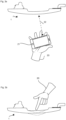
- FIG 3a The communication mode of the device is shown schematically.
- a user 20 approaches the vehicle door handle 1 with an NFC data transporter 21, in this case a smartphone.
- the NFC data carrier 21 is located a few centimeters away from the vehicle door handle 1, data communication 22 according to the known method is under the control of the control device 5 NFC standard between the near-field communication electronics in the vehicle door handle 1 and the NFC data carrier 21 possible.
- the control device 5 switches the electrodes 9a and 9b to a predetermined potential so that further NFC communication is not possible at this time longer is possible, but the coil 8 is used inside the vehicle door handle 1 as an inductive sensor.
- the different operating modes for the coil of the near-field communication device i.e. on the one hand the communication operation and on the other hand the sensor operation, can be carried out with temporal multiplexing, alternatively Sensor operation can only be activated after successful communication.
- the metallic component can also be placed in a handle wall or on the outside of the handle. It only needs to be ensured that the metallic component is within the detection range of the coil when it is operated as an inductive sensor.
Landscapes
- Engineering & Computer Science (AREA)
- Computer Networks & Wireless Communication (AREA)
- Remote Sensing (AREA)
- Signal Processing (AREA)
- Computer Security & Cryptography (AREA)
- Radar, Positioning & Navigation (AREA)
- Physics & Mathematics (AREA)
- General Physics & Mathematics (AREA)
- Lock And Its Accessories (AREA)
- Near-Field Transmission Systems (AREA)
Claims (10)
- Poignée de porte de véhicule (1) comprenant une manette (2) et au moins une section de fixation couplée à la manette (2) pour le montage de la manette (2) sur un véhicule,où la manette (2) comprend un boîtier et une électronique de communication en champ proche logée dans le boîtier,la manette (2) étant conçue de manière à ce que le boîtier soit déformé lorsqu'elle est actionnée,où l'électronique de communication en champ proche (7) présente un circuit oscillant avec une bobine (8) et où un circuit de commande (5) est couplé à l'électronique de communication en champ proche,où le circuit de commande (5) est conçu pour commander l'électronique de communication en champ proche dans un mode de communication, la bobine (8) pouvant fonctionner comme bobine d'émission/réception (8) pour une communication en champ proche,où le boîtier comprend au moins un composant métallique (9a, 9b) dans une zone qui est opposée à la bobine (8), le composant métallique étant conçu pour changer sa position par rapport à la bobine (8) lorsque le boîtier est déformé,le circuit de commande (5) étant conçu pour désactiver temporairement le mode de communication et pour commander la bobine (8) dans un mode capteur, le circuit de commande (5) étant conçu pour effectuer de manière répétée des mesures de l'inductance de la bobine (8) dans le mode capteur afin de détecter des déformations du boîtier,le circuit de commande (5) étant conçu pour fournir un signal d'actionnement en fonction de l'inductance de la bobine (8) lors de la commande de la bobine (8) en mode capteur.
- Poignée de porte de véhicule (1) selon la revendication 1, où le composant métallique (9a, 9b) est une couche métallique appliquée sur la face intérieure du boîtier ou sur la face extérieure du boîtier.
- Poignée de porte de véhicule (1) selon l'une quelconque des revendications précédentes, la bobine (8) étant réalisée sous forme de boucle conductrice sur une platine disposée dans le boîtier.
- Poignée de porte de véhicule (1) selon l'une quelconque des revendications précédentes, où le circuit de commande (5) est couplé électriquement au composant métallique (9a, 9b) et est configuré de manière à placer le composant métallique à un premier potentiel électrique lors du fonctionnement du dispositif de communication en champ proche dans le mode capteur.
- Poignée de porte de véhicule (1) selon la revendication 4, où le circuit de commande (5) est conçu de telle sorte qu'il met le composant métallique (9a, 9b) hors potentiel, flottant, dans le mode de communication lorsque le dispositif de communication en champ proche fonctionne.
- Procédé de communication en champ proche et de détection d'actionnements sur une poignée de porte de véhicule (1) comprenant une manette (2) et au moins une section de fixation couplée à la manette (2) pour monter la manette (2) sur un véhicule,où la manette (2) comprend un boîtier et une électronique de communication en champ proche logée dans le boîtier,le boîtier étant déformé lors de l'actionnement de la manette,où l'électronique de communication en champ proche présente un circuit oscillant avec une bobine (8) et où un circuit de commande (5) est couplé à l'électronique de communication en champ proche,où, pour effectuer une communication en champ proche sous le contrôle du circuit de commande (5), l'électronique de communication en champ proche fonctionne dans un mode de communication où la bobine (8) fonctionne comme une bobine d'émission/réception (8),où un composant métallique est couplé au boîtier dans une zone qui est opposée à la bobine (8), de sorte que le composant métallique est déplacé par rapport à la bobine (8) lorsque le boîtier est déformé,le circuit de commande désactivant temporairement le mode de communication et commandant la bobine (8) dans un mode de détection, le circuit de commande effectuant des mesures répétées de l'inductance de la bobine (8) afin de détecter des déformations du boîtier,le circuit de commande (5) fournissant un signal d'actionnement en fonction de l'inductance de la bobine (8).
- Procédé selon la revendication 6, où une couche métallique est appliquée sur la face intérieure du boîtier en tant que composant métallique.
- Procédé selon l'une quelconque des revendications 6 ou 7, où une platine disposée dans le boîtier est réalisée sous forme de boucle conductrice en tant que bobine (8).
- Procédé selon l'une quelconque des revendications 6 à 8, où le circuit de commande (5) est couplé au composant métallique et le composant métallique est placé à un premier potentiel électrique lors du fonctionnement du dispositif de communication en champ proche dans le mode capteur.
- Procédé selon l'une quelconque des revendications 6 à 9, où le circuit de commande (5) place le composant métallique à un potentiel flottant, libre de potentiel, lors du fonctionnement du dispositif de communication en champ proche dans le mode de communication.
Applications Claiming Priority (1)
| Application Number | Priority Date | Filing Date | Title |
|---|---|---|---|
| DE102018125922.0A DE102018125922A1 (de) | 2018-10-18 | 2018-10-18 | Fahrzeugtürgriff mit Nahfeld-Kommunikationselektronik |
Publications (2)
| Publication Number | Publication Date |
|---|---|
| EP3640896A1 EP3640896A1 (fr) | 2020-04-22 |
| EP3640896B1 true EP3640896B1 (fr) | 2024-02-14 |
Family
ID=67439072
Family Applications (1)
| Application Number | Title | Priority Date | Filing Date |
|---|---|---|---|
| EP19188577.1A Active EP3640896B1 (fr) | 2018-10-18 | 2019-07-26 | Poignée de porte de véhicule pourvue d'électronique de communication de champ proche |
Country Status (2)
| Country | Link |
|---|---|
| EP (1) | EP3640896B1 (fr) |
| DE (1) | DE102018125922A1 (fr) |
Families Citing this family (3)
| Publication number | Priority date | Publication date | Assignee | Title |
|---|---|---|---|---|
| DE102022126612A1 (de) * | 2022-10-12 | 2024-04-18 | Huf Hülsbeck & Fürst Gmbh & Co. Kg | Fahrzeugtür mit einer Griffanordnung |
| DE102023105204A1 (de) * | 2023-03-02 | 2024-09-05 | Bayerische Motoren Werke Aktiengesellschaft | Außengriff für ein Flügelelement für ein Fahrzeug, Anordnung eines Außengriffs an einem Flügelelement für ein Fahrzeug sowie Fahrzeug |
| DE102024116735A1 (de) | 2024-06-14 | 2025-12-18 | Huf Hülsbeck & Fürst Gmbh & Co. Kg | Schaltungsanordnung für einen Fahrzeuggriff |
Family Cites Families (2)
| Publication number | Priority date | Publication date | Assignee | Title |
|---|---|---|---|---|
| DE102013102701A1 (de) | 2013-03-18 | 2014-09-18 | Huf Hülsbeck & Fürst Gmbh & Co. Kg | Türgriffanordnung für ein Kraftfahrzeug mit kapazitivem Näherungssensor und NFC-Sende-/Empfangseinheit |
| WO2017009073A1 (fr) * | 2015-07-13 | 2017-01-19 | Huf Hülsbeck & Fürst Gmbh & Co. Kg | Poignée extérieure de porte pour véhicule |
-
2018
- 2018-10-18 DE DE102018125922.0A patent/DE102018125922A1/de not_active Withdrawn
-
2019
- 2019-07-26 EP EP19188577.1A patent/EP3640896B1/fr active Active
Non-Patent Citations (1)
| Title |
|---|
| MEINKE H: "Sensor-Messtechnik", 1 October 2012 (2012-10-01), pages 1 - 11, XP055835772, Retrieved from the Internet <URL:https://mb-bachelor.htw-berlin.de/files/Stg/MB/Versuchsanleitungen_Messtechnik/Sensor.pdf> [retrieved on 20210830] * |
Also Published As
| Publication number | Publication date |
|---|---|
| EP3640896A1 (fr) | 2020-04-22 |
| DE102018125922A1 (de) | 2020-04-23 |
Similar Documents
| Publication | Publication Date | Title |
|---|---|---|
| DE10148830B4 (de) | Verfahren und System zur Authentifizierung eines ersten Sende-/Empfangsgeräts gegenüber einem zu diesem entfernt angeordneten zweiten Sende-/Empfangsgerät | |
| DE69323995T2 (de) | Verfahren zum Abstimmen von elektronischen Antwortgeräten | |
| DE102014218213B4 (de) | Anordnung und Verfahren zum Detektieren der Annäherung eines Objektes | |
| EP2197714B1 (fr) | Localisation de clé flexible pour systèmes d'accès et d'authentification passifs | |
| EP2125449B1 (fr) | Procédé de caractérisation de distance pour des systèmes d'accès à couplage inductif pour véhicules | |
| EP2256662B1 (fr) | Procédé de détection de supports d'identification | |
| EP3640896B1 (fr) | Poignée de porte de véhicule pourvue d'électronique de communication de champ proche | |
| WO1999002377A1 (fr) | Dispositif de controle d'acces sans cle pour vehicules a moteur et procede pour realiser un controle d'autorisation d'acces sans cle dans un vehicule a moteur | |
| DE102005035935A1 (de) | Kraftfahrzeugtürgriff mit integriertem kapazitiven Sensor, induktiver Sendeantenne und einer Anordnung zum Vermindern von Fehlauslösungen des kapazitiven Sensors | |
| EP1479030A1 (fr) | Dispositif de commutation actionne par un transpondeur | |
| DE102020126533A1 (de) | UWB-Moduleinheit für ein Fahrzeug | |
| DE102007058278A1 (de) | Sicherheitsgurtsystem | |
| DE10222186C1 (de) | Sicherheitsschalter | |
| DE102014226925A1 (de) | Verfahren und Vorrichtung zur Zugangsverifizierung in einem Fahrzeug | |
| EP1083280B1 (fr) | Dispositif d'actionnement et/ou de fermeture sans clé, notamment pour véhicule automobile | |
| DE102014221933B4 (de) | Verhindern einer Funktionsstörung eines schlüssellosen Zugangsberechtigungssystems eines Kraftfahrzeugs durch das Wechselfeld einer induktiven Ladestation | |
| DE102016002302A1 (de) | Schließsystem, insbesondere für ein Kraftfahrzeug | |
| DE102007058277A1 (de) | Fahrzeuginsassen-Schutzvorrichtung | |
| EP1723615B1 (fr) | Composant inductif pour cle electronique | |
| DE10326676B4 (de) | Steuerungsvorrichtung für ein Kraftfahrzeuggetriebe und Kraftfahrzeuggetriebe | |
| DE102015222235B4 (de) | Tragbare Vorrichtung und Verfahren zum Aktivieren oder Deaktivieren eines Kraftfahrzeugs | |
| DE102014220399B4 (de) | Verfahren und Vorrichtung zur Zugangs- und Startverifizierung in einem Fahrzeug | |
| DE102004038837B4 (de) | Elektronisches Diebstahlschutzsystem mit korrelierten Sende-/Empfangsantennen | |
| DE102016218618A1 (de) | Vorrichtung und Verfahren zur Zugangs- und Startverifizierung in einem Fahrzeug | |
| EP1529222B1 (fr) | Dispositif et procede pour determiner la position d'un transpondeur |
Legal Events
| Date | Code | Title | Description |
|---|---|---|---|
| PUAI | Public reference made under article 153(3) epc to a published international application that has entered the european phase |
Free format text: ORIGINAL CODE: 0009012 |
|
| STAA | Information on the status of an ep patent application or granted ep patent |
Free format text: STATUS: THE APPLICATION HAS BEEN PUBLISHED |
|
| AK | Designated contracting states |
Kind code of ref document: A1 Designated state(s): AL AT BE BG CH CY CZ DE DK EE ES FI FR GB GR HR HU IE IS IT LI LT LU LV MC MK MT NL NO PL PT RO RS SE SI SK SM TR |
|
| AX | Request for extension of the european patent |
Extension state: BA ME |
|
| STAA | Information on the status of an ep patent application or granted ep patent |
Free format text: STATUS: REQUEST FOR EXAMINATION WAS MADE |
|
| 17P | Request for examination filed |
Effective date: 20200603 |
|
| RBV | Designated contracting states (corrected) |
Designated state(s): AL AT BE BG CH CY CZ DE DK EE ES FI FR GB GR HR HU IE IS IT LI LT LU LV MC MK MT NL NO PL PT RO RS SE SI SK SM TR |
|
| STAA | Information on the status of an ep patent application or granted ep patent |
Free format text: STATUS: EXAMINATION IS IN PROGRESS |
|
| 17Q | First examination report despatched |
Effective date: 20210907 |
|
| GRAP | Despatch of communication of intention to grant a patent |
Free format text: ORIGINAL CODE: EPIDOSNIGR1 |
|
| STAA | Information on the status of an ep patent application or granted ep patent |
Free format text: STATUS: GRANT OF PATENT IS INTENDED |
|
| RIC1 | Information provided on ipc code assigned before grant |
Ipc: H04B 5/00 20060101ALI20230926BHEP Ipc: H01Q 1/32 20060101ALI20230926BHEP Ipc: H03K 17/97 20060101ALI20230926BHEP Ipc: E05B 81/76 20140101ALI20230926BHEP Ipc: G07C 9/00 20200101AFI20230926BHEP |
|
| INTG | Intention to grant announced |
Effective date: 20231013 |
|
| GRAS | Grant fee paid |
Free format text: ORIGINAL CODE: EPIDOSNIGR3 |
|
| GRAA | (expected) grant |
Free format text: ORIGINAL CODE: 0009210 |
|
| STAA | Information on the status of an ep patent application or granted ep patent |
Free format text: STATUS: THE PATENT HAS BEEN GRANTED |
|
| AK | Designated contracting states |
Kind code of ref document: B1 Designated state(s): AL AT BE BG CH CY CZ DE DK EE ES FI FR GB GR HR HU IE IS IT LI LT LU LV MC MK MT NL NO PL PT RO RS SE SI SK SM TR |
|
| P01 | Opt-out of the competence of the unified patent court (upc) registered |
Effective date: 20240105 |
|
| REG | Reference to a national code |
Ref country code: GB Ref legal event code: FG4D Free format text: NOT ENGLISH |
|
| REG | Reference to a national code |
Ref country code: CH Ref legal event code: EP |
|
| REG | Reference to a national code |
Ref country code: DE Ref legal event code: R096 Ref document number: 502019010570 Country of ref document: DE |
|
| REG | Reference to a national code |
Ref country code: IE Ref legal event code: FG4D Free format text: LANGUAGE OF EP DOCUMENT: GERMAN |
|
| REG | Reference to a national code |
Ref country code: LT Ref legal event code: MG9D |
|
| REG | Reference to a national code |
Ref country code: NL Ref legal event code: MP Effective date: 20240214 |
|
| PG25 | Lapsed in a contracting state [announced via postgrant information from national office to epo] |
Ref country code: IS Free format text: LAPSE BECAUSE OF FAILURE TO SUBMIT A TRANSLATION OF THE DESCRIPTION OR TO PAY THE FEE WITHIN THE PRESCRIBED TIME-LIMIT Effective date: 20240614 |
|
| PG25 | Lapsed in a contracting state [announced via postgrant information from national office to epo] |
Ref country code: LT Free format text: LAPSE BECAUSE OF FAILURE TO SUBMIT A TRANSLATION OF THE DESCRIPTION OR TO PAY THE FEE WITHIN THE PRESCRIBED TIME-LIMIT Effective date: 20240214 |
|
| PG25 | Lapsed in a contracting state [announced via postgrant information from national office to epo] |
Ref country code: GR Free format text: LAPSE BECAUSE OF FAILURE TO SUBMIT A TRANSLATION OF THE DESCRIPTION OR TO PAY THE FEE WITHIN THE PRESCRIBED TIME-LIMIT Effective date: 20240515 |
|
| PG25 | Lapsed in a contracting state [announced via postgrant information from national office to epo] |
Ref country code: NL Free format text: LAPSE BECAUSE OF FAILURE TO SUBMIT A TRANSLATION OF THE DESCRIPTION OR TO PAY THE FEE WITHIN THE PRESCRIBED TIME-LIMIT Effective date: 20240214 Ref country code: RS Free format text: LAPSE BECAUSE OF FAILURE TO SUBMIT A TRANSLATION OF THE DESCRIPTION OR TO PAY THE FEE WITHIN THE PRESCRIBED TIME-LIMIT Effective date: 20240514 Ref country code: HR Free format text: LAPSE BECAUSE OF FAILURE TO SUBMIT A TRANSLATION OF THE DESCRIPTION OR TO PAY THE FEE WITHIN THE PRESCRIBED TIME-LIMIT Effective date: 20240214 |
|
| PG25 | Lapsed in a contracting state [announced via postgrant information from national office to epo] |
Ref country code: ES Free format text: LAPSE BECAUSE OF FAILURE TO SUBMIT A TRANSLATION OF THE DESCRIPTION OR TO PAY THE FEE WITHIN THE PRESCRIBED TIME-LIMIT Effective date: 20240214 |
|
| PG25 | Lapsed in a contracting state [announced via postgrant information from national office to epo] |
Ref country code: RS Free format text: LAPSE BECAUSE OF FAILURE TO SUBMIT A TRANSLATION OF THE DESCRIPTION OR TO PAY THE FEE WITHIN THE PRESCRIBED TIME-LIMIT Effective date: 20240514 Ref country code: NO Free format text: LAPSE BECAUSE OF FAILURE TO SUBMIT A TRANSLATION OF THE DESCRIPTION OR TO PAY THE FEE WITHIN THE PRESCRIBED TIME-LIMIT Effective date: 20240514 Ref country code: NL Free format text: LAPSE BECAUSE OF FAILURE TO SUBMIT A TRANSLATION OF THE DESCRIPTION OR TO PAY THE FEE WITHIN THE PRESCRIBED TIME-LIMIT Effective date: 20240214 Ref country code: LT Free format text: LAPSE BECAUSE OF FAILURE TO SUBMIT A TRANSLATION OF THE DESCRIPTION OR TO PAY THE FEE WITHIN THE PRESCRIBED TIME-LIMIT Effective date: 20240214 Ref country code: IS Free format text: LAPSE BECAUSE OF FAILURE TO SUBMIT A TRANSLATION OF THE DESCRIPTION OR TO PAY THE FEE WITHIN THE PRESCRIBED TIME-LIMIT Effective date: 20240614 Ref country code: HR Free format text: LAPSE BECAUSE OF FAILURE TO SUBMIT A TRANSLATION OF THE DESCRIPTION OR TO PAY THE FEE WITHIN THE PRESCRIBED TIME-LIMIT Effective date: 20240214 Ref country code: GR Free format text: LAPSE BECAUSE OF FAILURE TO SUBMIT A TRANSLATION OF THE DESCRIPTION OR TO PAY THE FEE WITHIN THE PRESCRIBED TIME-LIMIT Effective date: 20240515 Ref country code: FI Free format text: LAPSE BECAUSE OF FAILURE TO SUBMIT A TRANSLATION OF THE DESCRIPTION OR TO PAY THE FEE WITHIN THE PRESCRIBED TIME-LIMIT Effective date: 20240214 Ref country code: ES Free format text: LAPSE BECAUSE OF FAILURE TO SUBMIT A TRANSLATION OF THE DESCRIPTION OR TO PAY THE FEE WITHIN THE PRESCRIBED TIME-LIMIT Effective date: 20240214 Ref country code: BG Free format text: LAPSE BECAUSE OF FAILURE TO SUBMIT A TRANSLATION OF THE DESCRIPTION OR TO PAY THE FEE WITHIN THE PRESCRIBED TIME-LIMIT Effective date: 20240214 |
|
| PG25 | Lapsed in a contracting state [announced via postgrant information from national office to epo] |
Ref country code: PL Free format text: LAPSE BECAUSE OF FAILURE TO SUBMIT A TRANSLATION OF THE DESCRIPTION OR TO PAY THE FEE WITHIN THE PRESCRIBED TIME-LIMIT Effective date: 20240214 Ref country code: PT Free format text: LAPSE BECAUSE OF FAILURE TO SUBMIT A TRANSLATION OF THE DESCRIPTION OR TO PAY THE FEE WITHIN THE PRESCRIBED TIME-LIMIT Effective date: 20240614 |
|
| PG25 | Lapsed in a contracting state [announced via postgrant information from national office to epo] |
Ref country code: SE Free format text: LAPSE BECAUSE OF FAILURE TO SUBMIT A TRANSLATION OF THE DESCRIPTION OR TO PAY THE FEE WITHIN THE PRESCRIBED TIME-LIMIT Effective date: 20240214 Ref country code: PT Free format text: LAPSE BECAUSE OF FAILURE TO SUBMIT A TRANSLATION OF THE DESCRIPTION OR TO PAY THE FEE WITHIN THE PRESCRIBED TIME-LIMIT Effective date: 20240614 Ref country code: PL Free format text: LAPSE BECAUSE OF FAILURE TO SUBMIT A TRANSLATION OF THE DESCRIPTION OR TO PAY THE FEE WITHIN THE PRESCRIBED TIME-LIMIT Effective date: 20240214 Ref country code: LV Free format text: LAPSE BECAUSE OF FAILURE TO SUBMIT A TRANSLATION OF THE DESCRIPTION OR TO PAY THE FEE WITHIN THE PRESCRIBED TIME-LIMIT Effective date: 20240214 |
|
| PG25 | Lapsed in a contracting state [announced via postgrant information from national office to epo] |
Ref country code: DK Free format text: LAPSE BECAUSE OF FAILURE TO SUBMIT A TRANSLATION OF THE DESCRIPTION OR TO PAY THE FEE WITHIN THE PRESCRIBED TIME-LIMIT Effective date: 20240214 |
|
| PG25 | Lapsed in a contracting state [announced via postgrant information from national office to epo] |
Ref country code: SM Free format text: LAPSE BECAUSE OF FAILURE TO SUBMIT A TRANSLATION OF THE DESCRIPTION OR TO PAY THE FEE WITHIN THE PRESCRIBED TIME-LIMIT Effective date: 20240214 |
|
| PG25 | Lapsed in a contracting state [announced via postgrant information from national office to epo] |
Ref country code: CZ Free format text: LAPSE BECAUSE OF FAILURE TO SUBMIT A TRANSLATION OF THE DESCRIPTION OR TO PAY THE FEE WITHIN THE PRESCRIBED TIME-LIMIT Effective date: 20240214 Ref country code: EE Free format text: LAPSE BECAUSE OF FAILURE TO SUBMIT A TRANSLATION OF THE DESCRIPTION OR TO PAY THE FEE WITHIN THE PRESCRIBED TIME-LIMIT Effective date: 20240214 |
|
| PG25 | Lapsed in a contracting state [announced via postgrant information from national office to epo] |
Ref country code: SK Free format text: LAPSE BECAUSE OF FAILURE TO SUBMIT A TRANSLATION OF THE DESCRIPTION OR TO PAY THE FEE WITHIN THE PRESCRIBED TIME-LIMIT Effective date: 20240214 |
|
| PG25 | Lapsed in a contracting state [announced via postgrant information from national office to epo] |
Ref country code: SM Free format text: LAPSE BECAUSE OF FAILURE TO SUBMIT A TRANSLATION OF THE DESCRIPTION OR TO PAY THE FEE WITHIN THE PRESCRIBED TIME-LIMIT Effective date: 20240214 Ref country code: SK Free format text: LAPSE BECAUSE OF FAILURE TO SUBMIT A TRANSLATION OF THE DESCRIPTION OR TO PAY THE FEE WITHIN THE PRESCRIBED TIME-LIMIT Effective date: 20240214 Ref country code: RO Free format text: LAPSE BECAUSE OF FAILURE TO SUBMIT A TRANSLATION OF THE DESCRIPTION OR TO PAY THE FEE WITHIN THE PRESCRIBED TIME-LIMIT Effective date: 20240214 Ref country code: EE Free format text: LAPSE BECAUSE OF FAILURE TO SUBMIT A TRANSLATION OF THE DESCRIPTION OR TO PAY THE FEE WITHIN THE PRESCRIBED TIME-LIMIT Effective date: 20240214 Ref country code: DK Free format text: LAPSE BECAUSE OF FAILURE TO SUBMIT A TRANSLATION OF THE DESCRIPTION OR TO PAY THE FEE WITHIN THE PRESCRIBED TIME-LIMIT Effective date: 20240214 Ref country code: CZ Free format text: LAPSE BECAUSE OF FAILURE TO SUBMIT A TRANSLATION OF THE DESCRIPTION OR TO PAY THE FEE WITHIN THE PRESCRIBED TIME-LIMIT Effective date: 20240214 |
|
| REG | Reference to a national code |
Ref country code: DE Ref legal event code: R097 Ref document number: 502019010570 Country of ref document: DE |
|
| PG25 | Lapsed in a contracting state [announced via postgrant information from national office to epo] |
Ref country code: IT Free format text: LAPSE BECAUSE OF FAILURE TO SUBMIT A TRANSLATION OF THE DESCRIPTION OR TO PAY THE FEE WITHIN THE PRESCRIBED TIME-LIMIT Effective date: 20240214 |
|
| PLBE | No opposition filed within time limit |
Free format text: ORIGINAL CODE: 0009261 |
|
| STAA | Information on the status of an ep patent application or granted ep patent |
Free format text: STATUS: NO OPPOSITION FILED WITHIN TIME LIMIT |
|
| PG25 | Lapsed in a contracting state [announced via postgrant information from national office to epo] |
Ref country code: IT Free format text: LAPSE BECAUSE OF FAILURE TO SUBMIT A TRANSLATION OF THE DESCRIPTION OR TO PAY THE FEE WITHIN THE PRESCRIBED TIME-LIMIT Effective date: 20240214 |
|
| 26N | No opposition filed |
Effective date: 20241115 |
|
| PG25 | Lapsed in a contracting state [announced via postgrant information from national office to epo] |
Ref country code: MC Free format text: LAPSE BECAUSE OF FAILURE TO SUBMIT A TRANSLATION OF THE DESCRIPTION OR TO PAY THE FEE WITHIN THE PRESCRIBED TIME-LIMIT Effective date: 20240214 |
|
| REG | Reference to a national code |
Ref country code: CH Ref legal event code: PL |
|
| PG25 | Lapsed in a contracting state [announced via postgrant information from national office to epo] |
Ref country code: LU Free format text: LAPSE BECAUSE OF NON-PAYMENT OF DUE FEES Effective date: 20240726 |
|
| GBPC | Gb: european patent ceased through non-payment of renewal fee |
Effective date: 20240726 |
|
| PG25 | Lapsed in a contracting state [announced via postgrant information from national office to epo] |
Ref country code: LU Free format text: LAPSE BECAUSE OF NON-PAYMENT OF DUE FEES Effective date: 20240726 |
|
| PG25 | Lapsed in a contracting state [announced via postgrant information from national office to epo] |
Ref country code: CH Free format text: LAPSE BECAUSE OF NON-PAYMENT OF DUE FEES Effective date: 20240731 Ref country code: SI Free format text: LAPSE BECAUSE OF FAILURE TO SUBMIT A TRANSLATION OF THE DESCRIPTION OR TO PAY THE FEE WITHIN THE PRESCRIBED TIME-LIMIT Effective date: 20240214 Ref country code: BE Free format text: LAPSE BECAUSE OF NON-PAYMENT OF DUE FEES Effective date: 20240731 |
|
| PG25 | Lapsed in a contracting state [announced via postgrant information from national office to epo] |
Ref country code: GB Free format text: LAPSE BECAUSE OF NON-PAYMENT OF DUE FEES Effective date: 20240726 |
|
| REG | Reference to a national code |
Ref country code: BE Ref legal event code: MM Effective date: 20240731 |
|
| PG25 | Lapsed in a contracting state [announced via postgrant information from national office to epo] |
Ref country code: IE Free format text: LAPSE BECAUSE OF NON-PAYMENT OF DUE FEES Effective date: 20240726 |
|
| REG | Reference to a national code |
Ref country code: AT Ref legal event code: MM01 Ref document number: 1657714 Country of ref document: AT Kind code of ref document: T Effective date: 20240726 |
|
| PGFP | Annual fee paid to national office [announced via postgrant information from national office to epo] |
Ref country code: DE Payment date: 20250731 Year of fee payment: 7 |
|
| PG25 | Lapsed in a contracting state [announced via postgrant information from national office to epo] |
Ref country code: AT Free format text: LAPSE BECAUSE OF NON-PAYMENT OF DUE FEES Effective date: 20240726 |
|
| PGFP | Annual fee paid to national office [announced via postgrant information from national office to epo] |
Ref country code: FR Payment date: 20250723 Year of fee payment: 7 |
|
| PG25 | Lapsed in a contracting state [announced via postgrant information from national office to epo] |
Ref country code: CY Free format text: LAPSE BECAUSE OF FAILURE TO SUBMIT A TRANSLATION OF THE DESCRIPTION OR TO PAY THE FEE WITHIN THE PRESCRIBED TIME-LIMIT; INVALID AB INITIO Effective date: 20190726 |
|
| PG25 | Lapsed in a contracting state [announced via postgrant information from national office to epo] |
Ref country code: HU Free format text: LAPSE BECAUSE OF FAILURE TO SUBMIT A TRANSLATION OF THE DESCRIPTION OR TO PAY THE FEE WITHIN THE PRESCRIBED TIME-LIMIT; INVALID AB INITIO Effective date: 20190726 |