EP3640903B1 - Signalabhängige videoüberwachung - Google Patents
Signalabhängige videoüberwachung Download PDFInfo
- Publication number
- EP3640903B1 EP3640903B1 EP18201205.4A EP18201205A EP3640903B1 EP 3640903 B1 EP3640903 B1 EP 3640903B1 EP 18201205 A EP18201205 A EP 18201205A EP 3640903 B1 EP3640903 B1 EP 3640903B1
- Authority
- EP
- European Patent Office
- Prior art keywords
- surveillance
- area
- video camera
- control signal
- captured
- Prior art date
- Legal status (The legal status is an assumption and is not a legal conclusion. Google has not performed a legal analysis and makes no representation as to the accuracy of the status listed.)
- Active
Links
Images

Classifications
-
- G—PHYSICS
- G08—SIGNALLING
- G08B—SIGNALLING SYSTEMS, e.g. PERSONAL CALLING SYSTEMS; ORDER TELEGRAPHS; ALARM SYSTEMS
- G08B13/00—Burglar, theft or intruder alarms
- G08B13/18—Actuation by interference with heat, light, or radiation of shorter wavelength; Actuation by intruding sources of heat, light, or radiation of shorter wavelength
- G08B13/189—Actuation by interference with heat, light, or radiation of shorter wavelength; Actuation by intruding sources of heat, light, or radiation of shorter wavelength using passive radiation detection systems
- G08B13/194—Actuation by interference with heat, light, or radiation of shorter wavelength; Actuation by intruding sources of heat, light, or radiation of shorter wavelength using passive radiation detection systems using image scanning and comparing systems
- G08B13/196—Actuation by interference with heat, light, or radiation of shorter wavelength; Actuation by intruding sources of heat, light, or radiation of shorter wavelength using passive radiation detection systems using image scanning and comparing systems using television cameras
- G08B13/19678—User interface
- G08B13/19686—Interfaces masking personal details for privacy, e.g. blurring faces, vehicle license plates
-
- G—PHYSICS
- G06—COMPUTING OR CALCULATING; COUNTING
- G06T—IMAGE DATA PROCESSING OR GENERATION, IN GENERAL
- G06T7/00—Image analysis
- G06T7/20—Analysis of motion
-
- G—PHYSICS
- G06—COMPUTING OR CALCULATING; COUNTING
- G06V—IMAGE OR VIDEO RECOGNITION OR UNDERSTANDING
- G06V20/00—Scenes; Scene-specific elements
- G06V20/50—Context or environment of the image
- G06V20/52—Surveillance or monitoring of activities, e.g. for recognising suspicious objects
-
- G—PHYSICS
- G08—SIGNALLING
- G08B—SIGNALLING SYSTEMS, e.g. PERSONAL CALLING SYSTEMS; ORDER TELEGRAPHS; ALARM SYSTEMS
- G08B13/00—Burglar, theft or intruder alarms
- G08B13/18—Actuation by interference with heat, light, or radiation of shorter wavelength; Actuation by intruding sources of heat, light, or radiation of shorter wavelength
- G08B13/189—Actuation by interference with heat, light, or radiation of shorter wavelength; Actuation by intruding sources of heat, light, or radiation of shorter wavelength using passive radiation detection systems
- G08B13/194—Actuation by interference with heat, light, or radiation of shorter wavelength; Actuation by intruding sources of heat, light, or radiation of shorter wavelength using passive radiation detection systems using image scanning and comparing systems
- G08B13/196—Actuation by interference with heat, light, or radiation of shorter wavelength; Actuation by intruding sources of heat, light, or radiation of shorter wavelength using passive radiation detection systems using image scanning and comparing systems using television cameras
- G08B13/19695—Arrangements wherein non-video detectors start video recording or forwarding but do not generate an alarm themselves
-
- H—ELECTRICITY
- H04—ELECTRIC COMMUNICATION TECHNIQUE
- H04N—PICTORIAL COMMUNICATION, e.g. TELEVISION
- H04N7/00—Television systems
- H04N7/18—Closed-circuit television [CCTV] systems, i.e. systems in which the video signal is not broadcast
- H04N7/181—Closed-circuit television [CCTV] systems, i.e. systems in which the video signal is not broadcast for receiving images from a plurality of remote sources
-
- H—ELECTRICITY
- H04—ELECTRIC COMMUNICATION TECHNIQUE
- H04N—PICTORIAL COMMUNICATION, e.g. TELEVISION
- H04N7/00—Television systems
- H04N7/18—Closed-circuit television [CCTV] systems, i.e. systems in which the video signal is not broadcast
- H04N7/188—Capturing isolated or intermittent images triggered by the occurrence of a predetermined event, e.g. an object reaching a predetermined position
-
- G—PHYSICS
- G06—COMPUTING OR CALCULATING; COUNTING
- G06T—IMAGE DATA PROCESSING OR GENERATION, IN GENERAL
- G06T2207/00—Indexing scheme for image analysis or image enhancement
- G06T2207/10—Image acquisition modality
- G06T2207/10016—Video; Image sequence
-
- G—PHYSICS
- G06—COMPUTING OR CALCULATING; COUNTING
- G06T—IMAGE DATA PROCESSING OR GENERATION, IN GENERAL
- G06T2207/00—Indexing scheme for image analysis or image enhancement
- G06T2207/30—Subject of image; Context of image processing
- G06T2207/30232—Surveillance
Definitions
- the present invention refers to systems of video surveillance and particularly to a method for video surveillance.
- surveillance is the monitoring of behavior, activities, or other changing information for the purpose of influencing, managing, directing, or protecting people.
- This can include observation from a distance by means of electronic equipment, such as for example closed-circuit television (CCTV) cameras, or interception of electronically transmitted information such as Internet traffic or phone calls.
- CCTV closed-circuit television
- Surveillance for example, is used by governments for prevention of crime, the protection of a process, person, group or object or the investigation of crime. It is also used by private investigators and private people. Surveillance can be viewed as a violation of privacy, and as such is often opposed by various civil liberties groups and activists.
- Surveillance cameras are video cameras used for the purpose of observing an area.
- video surveillance systems there exist several video surveillance systems. For example, there are video surveillance systems continuously operating one or more video cameras recording video images. The adjustments, such as for example angle of view, vertical and horizontal orientation and zoom, once set, remain the same and are not automatically changeable, if at all.
- a human monitors the video images on a display and may manually adjust the settings of the one or more video cameras. The recorded video images are stored and can be maintained or deleted after a predetermined period of time. In any case, abuse of the image data by unauthorized people may occur.
- the video camera does not operate until a motion sensor indicates motion of a human, an animal or a vehicle. Then, upon detection of motion by the motion sensor, the video camera is turned-on. However, from detection of the motion until the start of operation by the video camera a time delay may result. Hence, the person detected by the motion sensor may have already disappeared and cannot be viewed in the recorded image. Examples for video surveillance systems are provided in US 2007/115356 , US 2013/070092 and US 5 111 288 .
- the objective technical problem underlying the invention is formulated as providing an improved system for video surveillance and a method for video surveillance in a video-surveillance system which allows properly capturing personal data in case of criminal activity, while taking into account the right of privacy in all other cases.
- the invention provides a method for video surveillance in a video-surveillance system according to claim 1. Preferred embodiments are defined in the dependent claims.
- Video surveillance means observing an area by a video camera.
- Video surveillance allows for monitoring or recording activity in and around an area of surveillance.
- the area of surveillance is the area that is observed by the video camera.
- the area of surveillance can be an indoor area or an outdoor area.
- the area of surveillance may refer to a passenger area, an inner area of a building, a public place and a private place.
- a public place may be for example a crossing in a city, a part of a walkway, a town square, or an entrance area at the outside of a building.
- a private place may be for example an office or any place belonging to a private person such as a flat, a house or a garden occupied by the private person.
- the area of surveillance i.e. the area that is observed by the video camera, can be any place that is to be observed.
- a video camera is a camera used for electronic motion picture acquisition by digital video capture.
- the video camera may capture a video image in which a scene, an event or an individual is visible.
- video cameras used for surveillance which are provided in different designs.
- CCTV generally uses pan tilt zoom cameras (PTZ) which contain mechanical controls that allow the operator to remotely pan (move left and right), tilt (move up and down), and zoom-in or -out the camera either by joystick or software.
- the PTZ camera for example, can automatically run patterns or turn to a preset position. Additionally, PTZ cameras can rotate 360 degrees to view an object directly below them.
- There are further designs and types of video cameras used for surveillance such as, for example, boxstyle camera, dome camera, bullet camera, IP camera, and day/night camera.
- the boxstyle camera for example, is comprised of the camera body, lens and power supply.
- the dome camera for example, is a half-spherical shaped camera.
- the bullet camera for example, has a bullet-like shape.
- the IP camera for example, streams its footage over the Internet.
- the IP camera can be wired or wireless.
- the day/night camera for example, has a movable Infrared (IR) filter.
- IR Infrared
- Video cameras can be used in two modes.
- the first mode is live television, where the camera feeds real time images directly to a screen for immediate observation.
- the images are recorded to a storage device for archiving or further processing. Recorded video is used in surveillance and monitoring tasks in which unattended recording of a situation is required for later analysis.
- Capturing video images means electronic motion picture acquisition by digital video through a video camera.
- An angle of view indicates the displayable range of the image (plane) measured by the angle from the center of the lens to the width of the image in the horizontal, vertical, and diagonal directions. These are called, horizontal angle of view, vertical angle of view and diagonal angle of view, respectively.
- the field of view is a measure of how large an area the camera is capable of viewing.
- the focal length of the lens affects the field of view. Zoom refers to changing a lens's focal length.
- Video camera technologies are, for example, WDR (Wide Dynamic Range), DNR (Digital Noise Reduction), Smart IR, and PoE (Power over Ethernet).
- WDR imaging is a method used to produce video images that try to recreate the full-scene content in scenes that have a dynamic range.
- DNR technology utilizes temporal noise reduction. The idea is that by blending the frames, the overall noise content in a video image is reduced.
- Smart IR is used to produce video images at night-time.
- PoE is a technology designed to deliver power to networking devices using existing data communications cabling.
- the video camera observing an area of surveillance may be mounted at the corner of a building, at the ceiling of a room, or at any position where a video camera can be mounted.
- Objects in the area of surveillance may be, for example, individuals and vehicles. However, objects can also be any item, such as, for example, a bag, a backpack or a suitcase.
- the step of "making objects in the area of surveillance invisible in the captured video images" functions as a "privacy filter". No personal data are obtained from objects in the area of surveillance, if the objects are invisible in the captured video images. In particular, as the objects are not visible in the captured video images, no personal data of an individual are captured, if one or more of the objects are individuals. Hence, an identification of the individuals is not possible. The right of privacy is preserved although the video camera is operating.
- Making objects in the area of surveillance invisible means, for example, that a user does not detect the objects in the captured video images, since there are no objects captured due to the field of view of the video camera that has been strongly restricted. By observing an area of surveillance and capturing video images in which objects are invisible, the right of privacy is protected.
- a processor receives a predetermined signal.
- the predetermined signal may be an alarm signal in the form of an electrical signal, a radio signal, and an optical signal.
- the predetermined signal received by the processor may have been transmitted from a sensor or input by a user.
- the processor may determine whether the predetermined signal has been received.
- the processor After having received the predetermined signal, the processor generates a first control signal and transmits the first control signal to the video camera.
- the first control signal can be in the form of an electrical signal, a radio signal, or an optical signal.
- the video camera receives the first control signal from the processor.
- the processor controls the video camera by the first control signal to stop the procedure of making objects in the area of surveillance invisible in the captured video images. Due to the received first control signal, the video camera, for example, enlarges the observed area visible on the captured video images by zooming, i.e. modifying the angle of view of the video camera.
- the stopping results in captured video images in which the objects are visible. For example, a face of a person or a licence plate number of a vehicle can be recognized.
- the predetermined signal may be caused by specific situations.
- the predetermined signal may be triggered by a sensor detecting a fulminating noise or a motion of an object.
- the predetermined signal occurs, for example, due to a scene, an event or an individual, that is to be captured by the video camera, the video camera is already operating and does not need time to be turned-on. Hence, a time delay caused by turning on the video camera is avoided such that video images of the scene, the event or the individual that is to be captured by the video camera can be immediately acquired.
- the scene may be, for example, a market place in a town, which is visited by many people who are to be protected against a terror attack, and where suspicious people or criminals are supposed to currently be there.
- the event may be a bank robbery captured by a video camera installed at the ceiling of a service hall of a bank.
- the individual in the captured video image for example, may be the bank robber or a car thief who just breaks the car open.
- the objects in the captured video images can be recognized as, for example, individuals, vehicles, buildings and so forth.
- the method according the invention may be further developed such that the captured video images comprise image data including personal data.
- the personal data preferably, comprise at least one of an individual, a face of an individual, a vehicle, and a license plate number of a vehicle.
- the method acquires personal data not until a predetermined signal occurs.
- the personal data allow identification of people.
- the method further comprises the steps of starting a timer when the first control signal has been transmitted to the video camera, when the timer elapses, generating a second control signal by the processor, transmitting the second control signal to the video camera, receiving the second control signal by the video camera, and, based on the received second control signal, starting making objects in the area of surveillance irrecognizable or invisible in the captured video images.
- a predetermined time period may be set by the timer.
- the predetermined time period may correspond to the time duration which starts when a situation triggering the predetermined signal occurs and ends when the situation ends.
- the video camera is controlled by the processor to start the procedure of making objects in the area of surveillance irrecognizable or invisible in the captured video images.
- the right of privacy is then preserved by making objects in the captured video images invisible. If a next situation occurs triggering the predetermined signal, the video camera is immediately operational and no time delay is caused by turning-on the video camera such that the object to be imaged can be viewed in the captured video image.
- the method further comprises the step of storing the captured video images after the step of stopping making objects in the area of surveillance irrecognizable or invisible in the captured video images.
- the processor may control the video camera to store the captured video images in a memory.
- the processor may control the video camera to transmit the captured video images to the processor.
- the processor may store the captured video images in the memory.
- the method further comprises the steps of analyzing, by the processor, the captured video images, after having stopped making objects in the area of surveillance irrecognizable or invisible in the captured video images, and identifying at least one object in the analyzed captured video images.
- the processor detects the face of the person in the captured video image by using a face recognition method and may try to match the detected face against faces in a database to identify the person.
- the database may be, for example, a police database, a national database, or an international database.
- the Internet and its content may also be used as "database”.
- Narrowing the area of surveillance means modifying the angle of view of the video camera such that it is zoomed-in to an extent such that merely a small part of the area of surveillance is captured by the video camera excluding any objects.
- the modification of the angle of view can be controlled by the processor.
- the step of making objects in the area of surveillance invisible in the captured video images further comprises temporarily storing the captured video images.
- the video camera may comprise a volatile storage for temporarily storing the captured video images.
- the video camera may also transmit the captured video images to a memory, where the captured video images are stored for a predetermined time period. After expiry of the predetermined time period, the stored video images may be deleted.
- the processor receives the predetermined signal from a sensor.
- the sensor may be, for example, a motion sensor detecting motion of an object in the area of surveillance.
- the sensor may be, for example, a acoustic sensor detecting ambient noise.
- the sensor may comprise a motion sensor and a acoustic sensor.
- the sensor may detect at least one of a noise, a sound, an object, and a motion of an object before transmitting the predetermined signal to the processor.
- the noise may be the noise of an explosion.
- the transmission of the first control signal, the second control signal, the predetermined signal, and data of the captured video images is performed via at least one of a wireless local area network (WLAN), a local area network (LAN), a radiocommunication, a serial digital interface (SDI), an Internet Protocol (IP), an analog high definition (AHD), or a power line network.
- WLAN wireless local area network
- LAN local area network
- SDI serial digital interface
- IP Internet Protocol
- AHD analog high definition
- the present invention also provides a system for video surveillance according to claim 8.
- Preferred embodiments are defined in the dependent claims.
- the system may comprise a plurality of video cameras. Further, the system may comprise a first memory.
- the video camera may comprise a second memory.
- the system may comprise a monitor for displaying captured video images and input means for providing input by a user.
- the video camera is one of a digital video camera and an analog video camera.
- the video camera may be rotatable, swiveling, moveable, inclinable, tiltable, usable indoors, and usable outdoors.
- the method for video surveillance in a video-surveillance system comprises the steps of capturing video images by a video camera observing an area of surveillance; wherein the capturing the video images comprises making objects in the area of surveillance invisible in captured video images; receiving, by a processor, a predetermined signal; based on the received predetermined signal, generating a first control signal by the processor and transmitting the first control signal to the video camera; receiving the first control signal by the video camera; based on the received first control signal, stopping making objects in the area of surveillance invisible in the captured video images.
- Fig. 1 illustrates a method for video surveillance in a video-surveillance system.
- a video camera observing an area of surveillance captures video images and makes objects in the area of surveillance invisible in the captured video images in step 101.
- a processor receives a predetermined signal.
- the predetermined signal may have been transmitted to the processor from a sensor or input by a user.
- the processor Based on the received predetermined signal, the processor generates a first control signal and transmits the first control signal to the video camera in step 103.
- the video camera receives the first control signal in step 104. Based on the received first control signal, the video camera stops making objects in the area of surveillance invisible in the captured video images in step 105.
- the processor may determine whether the predetermined signal has been received, and if it is determined that the predetermined signal is not received by the processor, the method 100 may continue with step 101. If it is determined that the predetermined signal is received by the processor, the method 100 may proceed with steps 103 to 105.
- a monitor may display clear video images captured by the video camera comprising visible and recognizable objects. Further, the processor may process image data of the captured video images. The processor may analyze the image data and extract personal data of at least one individual. Based on the extracted personal data, the at least one individual may be identified.
- the system for video surveillance comprises a video camera configured for observing an area of surveillance and capturing video images, wherein the video camera is further configured for making objects in the area of surveillance invisible in the captured video images, wherein the video camera is further configured for receiving a first control signal from a processor, based on the received first control signal, stopping making objects in the area of surveillance invisible in the captured video images; the processor configured for receiving a predetermined signal, based on the received predetermined signal, generating a first control signal and transmitting the first control signal to the video camera; and a sensor configured for generating the predetermined signal and transmitting the predetermined signal to the processor.
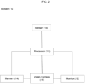
- Fig. 2 illustrates a system for video surveillance.
- system 10 comprises a processor 11, a monitor 12, a sensor 13, a memory 14, and a video camera 15.
- System 10 may comprise a plurality of video cameras 15.
- system 10 may comprise a further memory.
- System 10 may comprise input means being configured for receiving an input by a user.
- Sensor 13 may be a motion sensor, an acoustic sensor, or a combination of a motion sensor and an acoustic sensor. Sensor 13 may detect a motion, sound and/or noise. For example, the motion of an individual in a closed store may be detected by sensor 13. The individual in the closed store may be a theft. An individual may approach a work of art in a museum and may be detected by sensor 13. Sensor 13 may detect screams of an individual who feels threatened by another individual or who is watching a death-trap. For example, an individual may threaten another individual with a knife. Terrorists may threaten pedestrians at a public place with weapons. Sensor 13 is configured to generate a predetermined signal and transmit the predetermined signal to processor 11. The predetermined signal may be an alarm signal.
- Video camera 15 may be a digital video camera or an analog video camera.
- Video camera 15 is configured to observe an area of surveillance and capture video images, wherein video camera 15 makes objects in the area of surveillance invisible in the captured video images.
- Video camera 15 is turned-on and operating while making objects in the area of surveillance invisible in the captured video images.
- Video camera 15 may be configured to capture video images without capturing personal data.
- Video camera 15 may be set to narrow the observed area of surveillance by zooming such that objects are no longer visible. The settings may be stored in video camera 15. Not before video camera 15 receives a first control signal from processor 11, video camera 15 stops making objects in the area of surveillance invisible in the captured video images.
- Video camera 15 may operate in two different operating modes. In the first operating mode, video camera 15 may make objects in the area of surveillance invisible in the captured video images. In the second operating mode, video camera 15 may capture video images without making objects in the area of surveillance invisible in the captured video images, i.e., video camera 15 may stop making objects in the area of surveillance invisible in the captured video images.
- Processor 11 is configured to receive the predetermined signal from sensor 13, to generate the first control signal and transmit the first control signal to video camera 15.
- Video camera 15 is configured to receive the first control signal from processor 11. When video camera 15 receives the first control signal from processor 11, video camera 15 is configured to stop making objects in the area of surveillance invisible in the captured video images. Video camera 15 may be configured to capture video images with capturing personal data.
- Monitor 12 may be configured to display the video images captured by video camera 15.
- Memory 14 may be configured to store the captured video images.
Landscapes
- Engineering & Computer Science (AREA)
- Multimedia (AREA)
- Physics & Mathematics (AREA)
- General Physics & Mathematics (AREA)
- Signal Processing (AREA)
- Human Computer Interaction (AREA)
- Theoretical Computer Science (AREA)
- Computer Vision & Pattern Recognition (AREA)
- Studio Devices (AREA)
- Closed-Circuit Television Systems (AREA)
Claims (9)
- Verfahren zur Videoüberwachung in einem Videoüberwachungssystem, wobei das Verfahren die Schritte umfasst:Aufnehmen von Videobildern durch eine Videokamera, die einen Überwachungsbereich beobachtet, wobei die Videokamera durch eine Software gesteuert wird;wobei das Aufnehmen der Videobilder das Unsichtbarmachen von Objekten im Überwachungsbereich in aufgenommenen Videobildern durch Heranzoomen des Überwachungsbereichs in einem solchen Ausmaß, dass lediglich ein kleiner Teil des Überwachungsbereichs unter Ausschluss von Personen, Fahrzeugen und Gegenständen von der Videokamera aufgenommen wird, umfasst;Empfangen eines vorbestimmten Signals durch einen Prozessor;Erzeugen eines ersten Steuersignals durch den Prozessor auf der Grundlage des empfangenen vorbestimmten Signals und Übertragen des ersten Steuersignals an die Videokamera;Empfangen des ersten Steuersignals durch die Videokamera;basierend auf dem empfangenen ersten Steuersignal, beenden des Unsichtbarmachens von Objekten im Überwachungsbereich in den aufgenommenen Videobildern durch Herauszoomen des Überwachungsbereichs, was zu aufgenommenen Videobildern führt, in denen die Objekte sichtbar sind;weiterhin die Schritte umfassend:Starten eines Timers, wenn das erste Steuersignal an die Videokamera übertragen wurde;wenn der Timer abläuft, Erzeugen eines zweiten Steuersignals durch den Prozessor;Übertragen des zweiten Steuersignals an die Videokamera;Empfangen des zweiten Steuersignals durch die Videokamera; undauf der Grundlage des empfangenen zweiten Steuersignals mit Unsichtbarmachen von Objekten im Überwachungsbereich in den aufgenommenen Videobildern durch Heranzoomen des Überwachungsbereichs in einem solchen Ausmaß, dass lediglich ein kleiner Teil des Überwachungsbereichs unter Ausschluss von Personen, Fahrzeugen und Gegenständen von der Videokamera aufgenommen wird, beginnen.
- Das Verfahren nach Patentanspruch 1, ferner den Schritt umfassend:
nach dem Schritt des Beendens des Unsichtbarmachens von Objekten im Überwachungsbereich in den aufgenommenen Videobildern, Speichern der aufgenommenen Videobilder. - Das Verfahren nach Patentanspruch 1 oder 2, ferner die Schritte umfassend:nach dem Schritt des Beendens des Unsichtbarmachens von Objekten im Überwachungsbereich in den aufgenommenen Videobildern, Analysieren der aufgenommenen Videobilder durch den Prozessor; undIdentifizieren mindestens eines Objekts in den analysierten, aufgenommenen Videobildern.
- Das Verfahren nach einem der Patentansprüche 1 bis 3, wobei der Schritt des Unsichtbarmachens von Objekten im Überwachungsbereich in den aufgenommenen Videobildern weiterhin ein vorübergehendes Speichern der aufgenommenen Videobilder umfasst.
- Das Verfahren nach einem der Patentansprüche 1 bis 4, wobei das vorbestimmte Signal durch den Prozessor von einem Sensor empfangen wird.
- Das Verfahren nach Patentanspruch 5, wobei der Sensor ein Geräusch und/oder einen Ton und/oder ein Objekt und/oder eine Bewegung eines Objekts vor dem Übertragen des vorbestimmten Signals an den Prozessor erfasst.
- Das Verfahren nach einem der Patentansprüche 1 bis 6, wobei das Übertragen des ersten Steuersignals, eines zweiten Steuersignals, des vorbestimmten Signals und der Daten der aufgenommenen Videobilder über ein drahtloses lokales Netzwerk (WLAN), ein lokales Netzwerk (LAN), eine Funkverbindung, eine serielle digitale Schnittstelle (SDI), ein Internetprotokoll (IP), ein analoges hochauflösendes Netzwerk (AHD) oder ein Stromleitungsnetzwerk erfolgt.
- Ein System zur Videoüberwachung, wobei das System umfasst:eine Videokamera, die durch Software gesteuert wird und zum Beobachten eines Überwachungsbereichs und zum Aufnehmen von Videobildern konfiguriert ist, wobei die Videokamera ferner zum Unsichtbarmachen von Objekten in dem Überwachungsbereich in den aufgenommenen Videobildern durch Heranzoomen des Überwachungsbereichs in einem solchen Ausmaß, dass lediglich ein kleiner Teil des Überwachungsbereichs durch die Videokamera unter Ausschluss jeglicher Personen, Fahrzeuge und beliebige Gegenstände aufgenommen wird, konfiguriert ist, wobei die Videokamera ferner dazu konfiguriert ist, ein erstes Steuersignal von einem Prozessor zu empfangen und auf der Grundlage des empfangenen ersten Steuersignals das Unsichtbarmachen von Objekten in dem Überwachungsbereich in den aufgenommenen Videobildern durch Herauszoomen des Überwachungsbereichs zu beenden, was zu aufgenommenen Videobildern führt, in denen die Objekte sichtbar sind;den Prozessor, der dazu konfiguriert ist, ein vorbestimmtes Signal zu empfangen, auf der Grundlage des empfangenen vorbestimmten Signals ein erstes Steuersignal zu erzeugen und das erste Steuersignal an die Videokamera zu übertragen; undeinen Sensor, der dazu konfiguriert ist, das vorbestimmte Signal zu erzeugen und das vorbestimmte Signal an den Prozessor zu übertragen;einen Timer, der dazu konfiguriert ist, gestartet zu werden, wenn das erste Steuersignal an die Videokamera übertragen wurde;wobei, wenn der Timer abläuft, der Prozessor weiterhin dazu konfiguriert ist, ein zweites Steuersignal zu erzeugen und das zweite Steuersignal an die Videokamera zu übertragen;die Videokamera ist ferner dazu konfiguriert, das zweite Steuersignal zu empfangen und auf der Grundlage des empfangenen zweiten Steuersignals damit zu beginnen, Objekte im Überwachungsbereich in den aufgenommenen Videobildern unsichtbar zu machen, indem sie den Überwachungsbereich in einem solchen Ausmaß heranzoomt, dass nur ein kleiner Teil des Überwachungsbereichs von der Videokamera erfasst wird, wobei Personen, Fahrzeuge und Gegenstände ausgeschlossen sind.
- Das System nach Patentanspruch 8, wobei die Videokamera entweder eine digitale Videokamera oder eine analoge Videokamera ist.
Priority Applications (2)
| Application Number | Priority Date | Filing Date | Title |
|---|---|---|---|
| EP18201205.4A EP3640903B1 (de) | 2018-10-18 | 2018-10-18 | Signalabhängige videoüberwachung |
| US16/656,105 US11049377B2 (en) | 2018-10-18 | 2019-10-17 | Alarm dependent video surveillance |
Applications Claiming Priority (1)
| Application Number | Priority Date | Filing Date | Title |
|---|---|---|---|
| EP18201205.4A EP3640903B1 (de) | 2018-10-18 | 2018-10-18 | Signalabhängige videoüberwachung |
Publications (2)
| Publication Number | Publication Date |
|---|---|
| EP3640903A1 EP3640903A1 (de) | 2020-04-22 |
| EP3640903B1 true EP3640903B1 (de) | 2023-12-27 |
Family
ID=63914860
Family Applications (1)
| Application Number | Title | Priority Date | Filing Date |
|---|---|---|---|
| EP18201205.4A Active EP3640903B1 (de) | 2018-10-18 | 2018-10-18 | Signalabhängige videoüberwachung |
Country Status (2)
| Country | Link |
|---|---|
| US (1) | US11049377B2 (de) |
| EP (1) | EP3640903B1 (de) |
Families Citing this family (3)
| Publication number | Priority date | Publication date | Assignee | Title |
|---|---|---|---|---|
| EP4270940B1 (de) * | 2022-04-26 | 2024-10-30 | Axis AB | Ptz-maskierungssteuerung |
| US20240380868A1 (en) * | 2023-05-12 | 2024-11-14 | Climax Technology Co., Ltd. | Intruder detection system |
| CN119629468B (zh) * | 2025-02-06 | 2025-04-22 | 浙江大华技术股份有限公司 | 目标遮挡方法、目标遮挡装置、监控系统和存储介质 |
Citations (2)
| Publication number | Priority date | Publication date | Assignee | Title |
|---|---|---|---|---|
| US5111288A (en) * | 1988-03-02 | 1992-05-05 | Diamond Electronics, Inc. | Surveillance camera system |
| US20130070092A1 (en) * | 2011-09-20 | 2013-03-21 | Hitachi, Ltd. | Image device, surveillance camera, and mask method of camera screen |
Family Cites Families (40)
| Publication number | Priority date | Publication date | Assignee | Title |
|---|---|---|---|---|
| JP3681543B2 (ja) * | 1998-07-09 | 2005-08-10 | 松下電器産業株式会社 | 監視カメラ装置 |
| US6509926B1 (en) * | 2000-02-17 | 2003-01-21 | Sensormatic Electronics Corporation | Surveillance apparatus for camera surveillance system |
| AU2001247302A1 (en) * | 2000-03-10 | 2001-09-24 | Sensormatic Electronics Corporation | Method and apparatus for object surveillance with a movable camera |
| US7768546B1 (en) * | 2000-05-12 | 2010-08-03 | Axcess International, Inc. | Integrated security system and method |
| US20110058036A1 (en) * | 2000-11-17 | 2011-03-10 | E-Watch, Inc. | Bandwidth management and control |
| US7161615B2 (en) * | 2001-11-30 | 2007-01-09 | Pelco | System and method for tracking objects and obscuring fields of view under video surveillance |
| DE10158990C1 (de) * | 2001-11-30 | 2003-04-10 | Bosch Gmbh Robert | Videoüberwachungssystem |
| GB2404247B (en) * | 2003-07-22 | 2005-07-20 | Hitachi Int Electric Inc | Object tracing method and object tracking apparatus |
| WO2005015355A2 (en) * | 2003-08-07 | 2005-02-17 | Matsushita Electric Industrial Co., Ltd. | Automatic image cropping system and method for use with portable devices equipped with digital cameras |
| US9210312B2 (en) * | 2004-06-02 | 2015-12-08 | Bosch Security Systems, Inc. | Virtual mask for use in autotracking video camera images |
| US7493038B2 (en) * | 2004-12-15 | 2009-02-17 | Lg Electronics Inc. | Method and apparatus for controlling privacy mask display |
| KR101187756B1 (ko) * | 2005-11-07 | 2012-10-08 | 엘지전자 주식회사 | 감시용 카메라의 프라이버시 마스크 표시 제어방법 |
| WO2009001530A1 (ja) * | 2007-06-22 | 2008-12-31 | Panasonic Corporation | カメラ装置、および、撮影方法 |
| US8098282B2 (en) * | 2007-07-13 | 2012-01-17 | Honeywell International Inc. | Privacy zone algorithm for ptz dome cameras |
| US9241135B2 (en) * | 2007-08-15 | 2016-01-19 | At&T Intellectual Property I, Lp | Method and system for image alteration |
| US20090089828A1 (en) * | 2007-10-01 | 2009-04-02 | Shenzhen Tcl New Technology Ltd | Broadcast television parental control system and method |
| JP5312256B2 (ja) * | 2008-09-12 | 2013-10-09 | 三洋電機株式会社 | 撮像装置および撮像システム |
| US8488001B2 (en) * | 2008-12-10 | 2013-07-16 | Honeywell International Inc. | Semi-automatic relative calibration method for master slave camera control |
| US8576282B2 (en) * | 2008-12-12 | 2013-11-05 | Honeywell International Inc. | Security system with operator-side privacy zones |
| US10282563B2 (en) * | 2009-02-06 | 2019-05-07 | Tobii Ab | Video-based privacy supporting system |
| US9794518B2 (en) * | 2010-10-21 | 2017-10-17 | Sensormatic Electronics, LLC | Method and system for converting privacy zone planar images to their corresponding pan/tilt coordinates |
| US9230355B1 (en) * | 2014-08-21 | 2016-01-05 | Glu Mobile Inc. | Methods and systems for images with interactive filters |
| US9805445B2 (en) * | 2014-10-27 | 2017-10-31 | Adobe Systems Incorporated | Image zooming |
| JP6024999B2 (ja) * | 2014-11-26 | 2016-11-16 | パナソニックIpマネジメント株式会社 | 撮像装置、録画装置および映像出力制御装置 |
| WO2016123364A2 (en) * | 2015-01-28 | 2016-08-04 | Nextvr Inc. | Zoom related methods and apparatus |
| US10297126B2 (en) * | 2015-09-16 | 2019-05-21 | Sensormatic Electronics, LLC | Privacy masking video content of alarm exceptions and mask verification |
| WO2017083932A1 (en) * | 2015-11-18 | 2017-05-26 | Jorg Tilkin | Protection of privacy in video monitoring systems |
| JP6504364B2 (ja) * | 2015-11-27 | 2019-04-24 | パナソニックIpマネジメント株式会社 | モニタリング装置、モニタリングシステムおよびモニタリング方法 |
| GB201604409D0 (en) * | 2016-03-15 | 2016-04-27 | Smartwater Technology Ltd | Security marking system |
| US20170289504A1 (en) * | 2016-03-31 | 2017-10-05 | Ants Technology (Hk) Limited. | Privacy Supporting Computer Vision Systems, Methods, Apparatuses and Associated Computer Executable Code |
| US10313417B2 (en) * | 2016-04-18 | 2019-06-04 | Qualcomm Incorporated | Methods and systems for auto-zoom based adaptive video streaming |
| JP2018061211A (ja) * | 2016-10-07 | 2018-04-12 | パナソニックIpマネジメント株式会社 | 監視映像解析システム及び監視映像解析方法 |
| US10902147B2 (en) * | 2016-11-04 | 2021-01-26 | Intellisist, Inc. | System and method for performing screen capture-based sensitive information protection within a call center environment |
| DE102016223859A1 (de) * | 2016-11-30 | 2018-05-30 | Robert Bosch Gmbh | Kamera zur Überwachung eines Überwachungsbereiches und Überwachungsvorrichtung sowie Verfahren zur Überwachung eines Überwachungsbereiches |
| EP3340623B1 (de) * | 2016-12-20 | 2023-04-12 | Axis AB | Verfahren zur codierung eines bildes mit einer privatsphärenmaske |
| US10192061B2 (en) * | 2017-01-24 | 2019-01-29 | Wipro Limited | Method and a computing device for providing privacy control in a surveillance video |
| US10242282B2 (en) * | 2017-03-20 | 2019-03-26 | Conduent Business Services, Llc | Video redaction method and system |
| US20190045109A1 (en) * | 2017-08-02 | 2019-02-07 | Canon Kabushiki Kaisha | Information processing apparatus, information processing method, and storage medium |
| JP7071086B2 (ja) * | 2017-10-13 | 2022-05-18 | キヤノン株式会社 | 画像処理装置、画像処理方法及びコンピュータプログラム |
| US10922431B2 (en) * | 2017-12-27 | 2021-02-16 | Honeywell International Inc. | Systems and methods for dynamically masking video and images captured by a drone device camera |
-
2018
- 2018-10-18 EP EP18201205.4A patent/EP3640903B1/de active Active
-
2019
- 2019-10-17 US US16/656,105 patent/US11049377B2/en active Active
Patent Citations (2)
| Publication number | Priority date | Publication date | Assignee | Title |
|---|---|---|---|---|
| US5111288A (en) * | 1988-03-02 | 1992-05-05 | Diamond Electronics, Inc. | Surveillance camera system |
| US20130070092A1 (en) * | 2011-09-20 | 2013-03-21 | Hitachi, Ltd. | Image device, surveillance camera, and mask method of camera screen |
Also Published As
| Publication number | Publication date |
|---|---|
| US20200126383A1 (en) | 2020-04-23 |
| EP3640903A1 (de) | 2020-04-22 |
| US11049377B2 (en) | 2021-06-29 |
Similar Documents
| Publication | Publication Date | Title |
|---|---|---|
| Kruegle | CCTV Surveillance: Video practices and technology | |
| CN100504942C (zh) | 智能视频监控设备模组和系统及其监控方法 | |
| US9041800B2 (en) | Confined motion detection for pan-tilt cameras employing motion detection and autonomous motion tracking | |
| CN101123722B (zh) | 全景视频智能监控方法和系统 | |
| US20200327315A1 (en) | Monitoring systems | |
| CN101119482B (zh) | 一种全景监控方法及设备 | |
| US7535353B2 (en) | Surveillance system and surveillance method | |
| KR101471846B1 (ko) | Fx 감시카메라를 제어하는 콘트롤박스 및 fx 보안 시스템 및 fx 보안시스템 제어방법 | |
| US20140354820A1 (en) | System and method for live surveillance property monitoring | |
| KR101397453B1 (ko) | 영상 감시 시스템 및 그 방법 | |
| US11049377B2 (en) | Alarm dependent video surveillance | |
| KR101729966B1 (ko) | 화상 인식 및 음성 안내 기능이 구비된 cctv 카메라 시스템 및 그 동작 방법 | |
| US20170286762A1 (en) | Security camera system with projectile technology | |
| KR100967718B1 (ko) | 물체인식 정보를 이용한 영상 보안시스템 | |
| US20160198130A1 (en) | Surveillance method and surveillance system | |
| KR20130104582A (ko) | 시나리오 기반 출입 통제 시스템 및 방법 | |
| KR20010112180A (ko) | 움직임 추적 감시 및 격퇴 시스템 | |
| US20160044282A1 (en) | Desk-side surveillance | |
| KR101046819B1 (ko) | 소프트웨어 휀스에 의한 침입감시방법 및 침입감시시스템 | |
| KR101390179B1 (ko) | 불법 주정차 단속 및 방범 겸용 시스템 및 그 방법 | |
| KR101028524B1 (ko) | 입산 및 수영 금지구역 등의 출입금지 구역을 단속, 경고 및 홍보하는 cctv 시스템 및 그 구동방법 | |
| US20230098753A1 (en) | 360-degree panoramic image zoom display camera | |
| KR200266128Y1 (ko) | 움직임 추적 감시 및 격퇴 시스템 | |
| CN105939460A (zh) | 恢复摄像机位置用于播放视频场景的方法 | |
| KR101498494B1 (ko) | 다기능 감시 카메라 제어시스템 |
Legal Events
| Date | Code | Title | Description |
|---|---|---|---|
| PUAI | Public reference made under article 153(3) epc to a published international application that has entered the european phase |
Free format text: ORIGINAL CODE: 0009012 |
|
| STAA | Information on the status of an ep patent application or granted ep patent |
Free format text: STATUS: THE APPLICATION HAS BEEN PUBLISHED |
|
| AK | Designated contracting states |
Kind code of ref document: A1 Designated state(s): AL AT BE BG CH CY CZ DE DK EE ES FI FR GB GR HR HU IE IS IT LI LT LU LV MC MK MT NL NO PL PT RO RS SE SI SK SM TR |
|
| AX | Request for extension of the european patent |
Extension state: BA ME |
|
| STAA | Information on the status of an ep patent application or granted ep patent |
Free format text: STATUS: REQUEST FOR EXAMINATION WAS MADE |
|
| 17P | Request for examination filed |
Effective date: 20201013 |
|
| RBV | Designated contracting states (corrected) |
Designated state(s): AL AT BE BG CH CY CZ DE DK EE ES FI FR GB GR HR HU IE IS IT LI LT LU LV MC MK MT NL NO PL PT RO RS SE SI SK SM TR |
|
| STAA | Information on the status of an ep patent application or granted ep patent |
Free format text: STATUS: EXAMINATION IS IN PROGRESS |
|
| 17Q | First examination report despatched |
Effective date: 20210430 |
|
| GRAP | Despatch of communication of intention to grant a patent |
Free format text: ORIGINAL CODE: EPIDOSNIGR1 |
|
| STAA | Information on the status of an ep patent application or granted ep patent |
Free format text: STATUS: GRANT OF PATENT IS INTENDED |
|
| INTG | Intention to grant announced |
Effective date: 20230718 |
|
| P01 | Opt-out of the competence of the unified patent court (upc) registered |
Effective date: 20230915 |
|
| GRAS | Grant fee paid |
Free format text: ORIGINAL CODE: EPIDOSNIGR3 |
|
| GRAA | (expected) grant |
Free format text: ORIGINAL CODE: 0009210 |
|
| STAA | Information on the status of an ep patent application or granted ep patent |
Free format text: STATUS: THE PATENT HAS BEEN GRANTED |
|
| AK | Designated contracting states |
Kind code of ref document: B1 Designated state(s): AL AT BE BG CH CY CZ DE DK EE ES FI FR GB GR HR HU IE IS IT LI LT LU LV MC MK MT NL NO PL PT RO RS SE SI SK SM TR |
|
| REG | Reference to a national code |
Ref country code: GB Ref legal event code: FG4D |
|
| REG | Reference to a national code |
Ref country code: CH Ref legal event code: EP |
|
| REG | Reference to a national code |
Ref country code: DE Ref legal event code: R096 Ref document number: 602018063140 Country of ref document: DE |
|
| REG | Reference to a national code |
Ref country code: IE Ref legal event code: FG4D |
|
| PG25 | Lapsed in a contracting state [announced via postgrant information from national office to epo] |
Ref country code: GR Free format text: LAPSE BECAUSE OF FAILURE TO SUBMIT A TRANSLATION OF THE DESCRIPTION OR TO PAY THE FEE WITHIN THE PRESCRIBED TIME-LIMIT Effective date: 20240328 |
|
| REG | Reference to a national code |
Ref country code: LT Ref legal event code: MG9D |
|
| PG25 | Lapsed in a contracting state [announced via postgrant information from national office to epo] |
Ref country code: LT Free format text: LAPSE BECAUSE OF FAILURE TO SUBMIT A TRANSLATION OF THE DESCRIPTION OR TO PAY THE FEE WITHIN THE PRESCRIBED TIME-LIMIT Effective date: 20231227 |
|
| PG25 | Lapsed in a contracting state [announced via postgrant information from national office to epo] |
Ref country code: ES Free format text: LAPSE BECAUSE OF FAILURE TO SUBMIT A TRANSLATION OF THE DESCRIPTION OR TO PAY THE FEE WITHIN THE PRESCRIBED TIME-LIMIT Effective date: 20231227 |
|
| PG25 | Lapsed in a contracting state [announced via postgrant information from national office to epo] |
Ref country code: LT Free format text: LAPSE BECAUSE OF FAILURE TO SUBMIT A TRANSLATION OF THE DESCRIPTION OR TO PAY THE FEE WITHIN THE PRESCRIBED TIME-LIMIT Effective date: 20231227 Ref country code: GR Free format text: LAPSE BECAUSE OF FAILURE TO SUBMIT A TRANSLATION OF THE DESCRIPTION OR TO PAY THE FEE WITHIN THE PRESCRIBED TIME-LIMIT Effective date: 20240328 Ref country code: FI Free format text: LAPSE BECAUSE OF FAILURE TO SUBMIT A TRANSLATION OF THE DESCRIPTION OR TO PAY THE FEE WITHIN THE PRESCRIBED TIME-LIMIT Effective date: 20231227 Ref country code: ES Free format text: LAPSE BECAUSE OF FAILURE TO SUBMIT A TRANSLATION OF THE DESCRIPTION OR TO PAY THE FEE WITHIN THE PRESCRIBED TIME-LIMIT Effective date: 20231227 Ref country code: BG Free format text: LAPSE BECAUSE OF FAILURE TO SUBMIT A TRANSLATION OF THE DESCRIPTION OR TO PAY THE FEE WITHIN THE PRESCRIBED TIME-LIMIT Effective date: 20240327 |
|
| REG | Reference to a national code |
Ref country code: NL Ref legal event code: MP Effective date: 20231227 |
|
| REG | Reference to a national code |
Ref country code: AT Ref legal event code: MK05 Ref document number: 1645271 Country of ref document: AT Kind code of ref document: T Effective date: 20231227 |
|
| PG25 | Lapsed in a contracting state [announced via postgrant information from national office to epo] |
Ref country code: NL Free format text: LAPSE BECAUSE OF FAILURE TO SUBMIT A TRANSLATION OF THE DESCRIPTION OR TO PAY THE FEE WITHIN THE PRESCRIBED TIME-LIMIT Effective date: 20231227 |
|
| PG25 | Lapsed in a contracting state [announced via postgrant information from national office to epo] |
Ref country code: SE Free format text: LAPSE BECAUSE OF FAILURE TO SUBMIT A TRANSLATION OF THE DESCRIPTION OR TO PAY THE FEE WITHIN THE PRESCRIBED TIME-LIMIT Effective date: 20231227 Ref country code: RS Free format text: LAPSE BECAUSE OF FAILURE TO SUBMIT A TRANSLATION OF THE DESCRIPTION OR TO PAY THE FEE WITHIN THE PRESCRIBED TIME-LIMIT Effective date: 20231227 Ref country code: NO Free format text: LAPSE BECAUSE OF FAILURE TO SUBMIT A TRANSLATION OF THE DESCRIPTION OR TO PAY THE FEE WITHIN THE PRESCRIBED TIME-LIMIT Effective date: 20240327 Ref country code: NL Free format text: LAPSE BECAUSE OF FAILURE TO SUBMIT A TRANSLATION OF THE DESCRIPTION OR TO PAY THE FEE WITHIN THE PRESCRIBED TIME-LIMIT Effective date: 20231227 Ref country code: LV Free format text: LAPSE BECAUSE OF FAILURE TO SUBMIT A TRANSLATION OF THE DESCRIPTION OR TO PAY THE FEE WITHIN THE PRESCRIBED TIME-LIMIT Effective date: 20231227 Ref country code: HR Free format text: LAPSE BECAUSE OF FAILURE TO SUBMIT A TRANSLATION OF THE DESCRIPTION OR TO PAY THE FEE WITHIN THE PRESCRIBED TIME-LIMIT Effective date: 20231227 |
|
| PG25 | Lapsed in a contracting state [announced via postgrant information from national office to epo] |
Ref country code: IS Free format text: LAPSE BECAUSE OF FAILURE TO SUBMIT A TRANSLATION OF THE DESCRIPTION OR TO PAY THE FEE WITHIN THE PRESCRIBED TIME-LIMIT Effective date: 20240427 |
|
| PG25 | Lapsed in a contracting state [announced via postgrant information from national office to epo] |
Ref country code: AT Free format text: LAPSE BECAUSE OF FAILURE TO SUBMIT A TRANSLATION OF THE DESCRIPTION OR TO PAY THE FEE WITHIN THE PRESCRIBED TIME-LIMIT Effective date: 20231227 Ref country code: CZ Free format text: LAPSE BECAUSE OF FAILURE TO SUBMIT A TRANSLATION OF THE DESCRIPTION OR TO PAY THE FEE WITHIN THE PRESCRIBED TIME-LIMIT Effective date: 20231227 |
|
| PG25 | Lapsed in a contracting state [announced via postgrant information from national office to epo] |
Ref country code: SK Free format text: LAPSE BECAUSE OF FAILURE TO SUBMIT A TRANSLATION OF THE DESCRIPTION OR TO PAY THE FEE WITHIN THE PRESCRIBED TIME-LIMIT Effective date: 20231227 |
|
| PG25 | Lapsed in a contracting state [announced via postgrant information from national office to epo] |
Ref country code: SM Free format text: LAPSE BECAUSE OF FAILURE TO SUBMIT A TRANSLATION OF THE DESCRIPTION OR TO PAY THE FEE WITHIN THE PRESCRIBED TIME-LIMIT Effective date: 20231227 Ref country code: SK Free format text: LAPSE BECAUSE OF FAILURE TO SUBMIT A TRANSLATION OF THE DESCRIPTION OR TO PAY THE FEE WITHIN THE PRESCRIBED TIME-LIMIT Effective date: 20231227 Ref country code: RO Free format text: LAPSE BECAUSE OF FAILURE TO SUBMIT A TRANSLATION OF THE DESCRIPTION OR TO PAY THE FEE WITHIN THE PRESCRIBED TIME-LIMIT Effective date: 20231227 Ref country code: IT Free format text: LAPSE BECAUSE OF FAILURE TO SUBMIT A TRANSLATION OF THE DESCRIPTION OR TO PAY THE FEE WITHIN THE PRESCRIBED TIME-LIMIT Effective date: 20231227 Ref country code: IS Free format text: LAPSE BECAUSE OF FAILURE TO SUBMIT A TRANSLATION OF THE DESCRIPTION OR TO PAY THE FEE WITHIN THE PRESCRIBED TIME-LIMIT Effective date: 20240427 Ref country code: EE Free format text: LAPSE BECAUSE OF FAILURE TO SUBMIT A TRANSLATION OF THE DESCRIPTION OR TO PAY THE FEE WITHIN THE PRESCRIBED TIME-LIMIT Effective date: 20231227 Ref country code: CZ Free format text: LAPSE BECAUSE OF FAILURE TO SUBMIT A TRANSLATION OF THE DESCRIPTION OR TO PAY THE FEE WITHIN THE PRESCRIBED TIME-LIMIT Effective date: 20231227 Ref country code: AT Free format text: LAPSE BECAUSE OF FAILURE TO SUBMIT A TRANSLATION OF THE DESCRIPTION OR TO PAY THE FEE WITHIN THE PRESCRIBED TIME-LIMIT Effective date: 20231227 |
|
| PG25 | Lapsed in a contracting state [announced via postgrant information from national office to epo] |
Ref country code: PL Free format text: LAPSE BECAUSE OF FAILURE TO SUBMIT A TRANSLATION OF THE DESCRIPTION OR TO PAY THE FEE WITHIN THE PRESCRIBED TIME-LIMIT Effective date: 20231227 Ref country code: PT Free format text: LAPSE BECAUSE OF FAILURE TO SUBMIT A TRANSLATION OF THE DESCRIPTION OR TO PAY THE FEE WITHIN THE PRESCRIBED TIME-LIMIT Effective date: 20240429 |
|
| PG25 | Lapsed in a contracting state [announced via postgrant information from national office to epo] |
Ref country code: PT Free format text: LAPSE BECAUSE OF FAILURE TO SUBMIT A TRANSLATION OF THE DESCRIPTION OR TO PAY THE FEE WITHIN THE PRESCRIBED TIME-LIMIT Effective date: 20240429 Ref country code: PL Free format text: LAPSE BECAUSE OF FAILURE TO SUBMIT A TRANSLATION OF THE DESCRIPTION OR TO PAY THE FEE WITHIN THE PRESCRIBED TIME-LIMIT Effective date: 20231227 |
|
| REG | Reference to a national code |
Ref country code: DE Ref legal event code: R097 Ref document number: 602018063140 Country of ref document: DE |
|
| PG25 | Lapsed in a contracting state [announced via postgrant information from national office to epo] |
Ref country code: DK Free format text: LAPSE BECAUSE OF FAILURE TO SUBMIT A TRANSLATION OF THE DESCRIPTION OR TO PAY THE FEE WITHIN THE PRESCRIBED TIME-LIMIT Effective date: 20231227 |
|
| PG25 | Lapsed in a contracting state [announced via postgrant information from national office to epo] |
Ref country code: DK Free format text: LAPSE BECAUSE OF FAILURE TO SUBMIT A TRANSLATION OF THE DESCRIPTION OR TO PAY THE FEE WITHIN THE PRESCRIBED TIME-LIMIT Effective date: 20231227 |
|
| PLBE | No opposition filed within time limit |
Free format text: ORIGINAL CODE: 0009261 |
|
| STAA | Information on the status of an ep patent application or granted ep patent |
Free format text: STATUS: NO OPPOSITION FILED WITHIN TIME LIMIT |
|
| 26N | No opposition filed |
Effective date: 20240930 |
|
| PG25 | Lapsed in a contracting state [announced via postgrant information from national office to epo] |
Ref country code: SI Free format text: LAPSE BECAUSE OF FAILURE TO SUBMIT A TRANSLATION OF THE DESCRIPTION OR TO PAY THE FEE WITHIN THE PRESCRIBED TIME-LIMIT Effective date: 20231227 |
|
| PG25 | Lapsed in a contracting state [announced via postgrant information from national office to epo] |
Ref country code: MC Free format text: LAPSE BECAUSE OF FAILURE TO SUBMIT A TRANSLATION OF THE DESCRIPTION OR TO PAY THE FEE WITHIN THE PRESCRIBED TIME-LIMIT Effective date: 20231227 |
|
| PG25 | Lapsed in a contracting state [announced via postgrant information from national office to epo] |
Ref country code: BE Free format text: LAPSE BECAUSE OF NON-PAYMENT OF DUE FEES Effective date: 20241031 Ref country code: LU Free format text: LAPSE BECAUSE OF NON-PAYMENT OF DUE FEES Effective date: 20241018 |
|
| REG | Reference to a national code |
Ref country code: BE Ref legal event code: MM Effective date: 20241031 |
|
| PG25 | Lapsed in a contracting state [announced via postgrant information from national office to epo] |
Ref country code: IE Free format text: LAPSE BECAUSE OF NON-PAYMENT OF DUE FEES Effective date: 20241018 |
|
| REG | Reference to a national code |
Ref country code: CH Ref legal event code: U11 Free format text: ST27 STATUS EVENT CODE: U-0-0-U10-U11 (AS PROVIDED BY THE NATIONAL OFFICE) Effective date: 20251101 |
|
| PGFP | Annual fee paid to national office [announced via postgrant information from national office to epo] |
Ref country code: DE Payment date: 20251029 Year of fee payment: 8 |
|
| PGFP | Annual fee paid to national office [announced via postgrant information from national office to epo] |
Ref country code: GB Payment date: 20251024 Year of fee payment: 8 |
|
| PGFP | Annual fee paid to national office [announced via postgrant information from national office to epo] |
Ref country code: FR Payment date: 20251024 Year of fee payment: 8 |
|
| PGFP | Annual fee paid to national office [announced via postgrant information from national office to epo] |
Ref country code: CH Payment date: 20251101 Year of fee payment: 8 |
|
| PG25 | Lapsed in a contracting state [announced via postgrant information from national office to epo] |
Ref country code: CY Free format text: LAPSE BECAUSE OF FAILURE TO SUBMIT A TRANSLATION OF THE DESCRIPTION OR TO PAY THE FEE WITHIN THE PRESCRIBED TIME-LIMIT; INVALID AB INITIO Effective date: 20181018 |
|
| PG25 | Lapsed in a contracting state [announced via postgrant information from national office to epo] |
Ref country code: HU Free format text: LAPSE BECAUSE OF FAILURE TO SUBMIT A TRANSLATION OF THE DESCRIPTION OR TO PAY THE FEE WITHIN THE PRESCRIBED TIME-LIMIT; INVALID AB INITIO Effective date: 20181018 |