EP3641105A1 - Moteur à courant continu et son procédé de fabrication - Google Patents
Moteur à courant continu et son procédé de fabrication Download PDFInfo
- Publication number
- EP3641105A1 EP3641105A1 EP19201048.6A EP19201048A EP3641105A1 EP 3641105 A1 EP3641105 A1 EP 3641105A1 EP 19201048 A EP19201048 A EP 19201048A EP 3641105 A1 EP3641105 A1 EP 3641105A1
- Authority
- EP
- European Patent Office
- Prior art keywords
- stator
- motor
- contact
- winding
- motor according
- Prior art date
- Legal status (The legal status is an assumption and is not a legal conclusion. Google has not performed a legal analysis and makes no representation as to the accuracy of the status listed.)
- Granted
Links
Images





Classifications
-
- H—ELECTRICITY
- H02—GENERATION; CONVERSION OR DISTRIBUTION OF ELECTRIC POWER
- H02K—DYNAMO-ELECTRIC MACHINES
- H02K3/00—Details of windings
- H02K3/46—Fastening of windings on the stator or rotor structure
- H02K3/52—Fastening salient pole windings or connections thereto
- H02K3/521—Fastening salient pole windings or connections thereto applicable to stators only
- H02K3/522—Fastening salient pole windings or connections thereto applicable to stators only for generally annular cores with salient poles
-
- H—ELECTRICITY
- H02—GENERATION; CONVERSION OR DISTRIBUTION OF ELECTRIC POWER
- H02K—DYNAMO-ELECTRIC MACHINES
- H02K15/00—Processes or apparatus specially adapted for manufacturing, assembling, maintaining or repairing of dynamo-electric machines
- H02K15/08—Forming windings by laying conductors into or around core parts
- H02K15/085—Forming windings by laying conductors into or around core parts by laying conductors into slotted stators
-
- H—ELECTRICITY
- H02—GENERATION; CONVERSION OR DISTRIBUTION OF ELECTRIC POWER
- H02K—DYNAMO-ELECTRIC MACHINES
- H02K15/00—Processes or apparatus specially adapted for manufacturing, assembling, maintaining or repairing of dynamo-electric machines
- H02K15/08—Forming windings by laying conductors into or around core parts
- H02K15/095—Forming windings by laying conductors into or around core parts by laying conductors around salient poles
-
- H—ELECTRICITY
- H02—GENERATION; CONVERSION OR DISTRIBUTION OF ELECTRIC POWER
- H02K—DYNAMO-ELECTRIC MACHINES
- H02K15/00—Processes or apparatus specially adapted for manufacturing, assembling, maintaining or repairing of dynamo-electric machines
- H02K15/10—Applying solid insulation to windings, stators or rotors, e.g. applying insulating tapes
- H02K15/105—Applying solid insulation to windings, stators or rotors, e.g. applying insulating tapes to the windings
-
- H—ELECTRICITY
- H02—GENERATION; CONVERSION OR DISTRIBUTION OF ELECTRIC POWER
- H02K—DYNAMO-ELECTRIC MACHINES
- H02K15/00—Processes or apparatus specially adapted for manufacturing, assembling, maintaining or repairing of dynamo-electric machines
- H02K15/30—Manufacture of winding connections
- H02K15/33—Connecting winding sections; Forming leads; Connecting leads to terminals
-
- H—ELECTRICITY
- H02—GENERATION; CONVERSION OR DISTRIBUTION OF ELECTRIC POWER
- H02K—DYNAMO-ELECTRIC MACHINES
- H02K3/00—Details of windings
- H02K3/04—Windings characterised by the conductor shape, form or construction, e.g. with bar conductors
- H02K3/28—Layout of windings or of connections between windings
-
- H—ELECTRICITY
- H02—GENERATION; CONVERSION OR DISTRIBUTION OF ELECTRIC POWER
- H02K—DYNAMO-ELECTRIC MACHINES
- H02K3/00—Details of windings
- H02K3/32—Windings characterised by the shape, form or construction of the insulation
- H02K3/34—Windings characterised by the shape, form or construction of the insulation between conductors or between conductor and core, e.g. slot insulation
- H02K3/345—Windings characterised by the shape, form or construction of the insulation between conductors or between conductor and core, e.g. slot insulation between conductor and core, e.g. slot insulation
-
- H—ELECTRICITY
- H02—GENERATION; CONVERSION OR DISTRIBUTION OF ELECTRIC POWER
- H02K—DYNAMO-ELECTRIC MACHINES
- H02K3/00—Details of windings
- H02K3/32—Windings characterised by the shape, form or construction of the insulation
- H02K3/38—Windings characterised by the shape, form or construction of the insulation around winding heads, equalising connectors, or connections thereto
-
- H—ELECTRICITY
- H02—GENERATION; CONVERSION OR DISTRIBUTION OF ELECTRIC POWER
- H02K—DYNAMO-ELECTRIC MACHINES
- H02K2203/00—Specific aspects not provided for in the other groups of this subclass relating to the windings
- H02K2203/09—Machines characterised by wiring elements other than wires, e.g. bus rings, for connecting the winding terminations
-
- H—ELECTRICITY
- H02—GENERATION; CONVERSION OR DISTRIBUTION OF ELECTRIC POWER
- H02K—DYNAMO-ELECTRIC MACHINES
- H02K2203/00—Specific aspects not provided for in the other groups of this subclass relating to the windings
- H02K2203/12—Machines characterised by the bobbins for supporting the windings
Definitions
- the invention relates to a direct current motor (1) with a permanent magnetic inner rotor (2) rotatably mounted about a motor longitudinal axis (19) and a stator (30), consisting of a wound stator core (3) with a plurality of pronounced inward poles (4). , which are integral with a return ring (5) in the circumferential direction and separated from one another by stator grooves (6), an insulating body (7) which lines the stator grooves (6) and has a return ring cover (8) which has an axial end face of the return ring (5 ), one winding wire (10) being wound continuously and without interruption successively around all poles (4) to form one coil (39) each, and the coils are connected in a triangular-parallel arrangement.
- Stator cores with pronounced poles can be one or more parts. With multi-part stator cores, the poles can be individually z. B. wrap with a flyer. The multiple interrupted magnetic circuit, however, significantly reduces the efficiency, which is why stator cores are often made in one piece in the direction of the magnetic field lines.
- One-piece stator cores can consist of a stack of sheets or of pressed metal powder; they are usually wound by a needle winder. This requires a hollow winding needle in which the winding wire is passed. The winding needle has a minimum diameter depending on the wire diameter. A minimum distance between the winding needle and stator components must also be maintained for reliable production.
- the object of the invention is therefore to provide for a generic DC motor for a compact structure, reliable production, easy assembly and good efficiency.
- the winding wire (10) forms a U-shaped wire connection (18) between two coils (39) which are spatially adjacent in the circumferential direction and which connect a first leg (51), a second leg (52) and one of the two legs (51, 52)
- Contact section (20) which is arranged axially beyond a winding head and radially a clear distance from a cylindrical envelope of the stator core (3) and the insulating body (7) does not radially enlarge the space of the stator (30), a process reliable Implementation with freely accessible contact areas and easy-to-assemble individual parts.
- the space should not be radially expanded by other components that are required for contacting the winding.
- the wire connection (18) does not run around deflecting geometries of the insulating material body (7) projecting axially or radially outward, because each additional deflection of the winding wire increases the cycle times during production and increases tool wear.
- the present invention relates in particular to DC motors in which the winding direction of coils which are spatially adjacent in the circumferential direction is in opposite directions.
- the wire connection (18) is between two spatially adjacent coil sides of two adjacent coils (39).
- the contact section (20) is arranged axially beyond the insulating body (7). As a result, the contact section (20) is easily accessible from all sides and prepared for contacting.
- an angle between one leg (51 or 52) of the wire connection (18) and the motor longitudinal axis (19) is less than or equal to 45 °, in particular less than or equal to 30 °, in particular less than or equal to 15 ° , in particular less than or equal to 10 °, in particular less than or equal to 5 °, in particular less than or equal to 2 °, in particular less than or equal to 1 °, in particular equal to 0 °.
- the distances between adjacent contacts on the one hand and opposing contacts on the other hand are larger. It is therefore preferred to align the legs (51 or 52) as parallel as possible to the longitudinal axis of the motor. This also gives the contact sections (20) a sufficient distance from a radial delimitation of a stator installation space.
- the contact section (20) of the wire connection (18) is easily accessible, it is easier to make electrical contact with a contact hook (17) of a contact unit (16). It should be noted that the contact hook (17) has a clear distance from an outer edge of the stator core (3). This configuration ensures that no radial construction beyond the stator core (3) is necessary. This enables a compact motor structure to be realized and the risk of short circuits reduced. Slight inaccuracies in the radial position of the contact sections (20) can be compensated for by the contact hooks (17).
- the contact hooks (17) lie on a reference circle (50).
- the reference circle (50) is defined by the maximum slot depth of a stator slot (6). In this position, the contact section (20) and the contact hooks (17) are sufficiently removed from a motor housing (15) and the necessary creepage distances are maintained.
- the distal end of the contact hook (17) is closed.
- the contact hooks (17) are open when they are installed trained so that they can be easily axially joined.
- the two legs of the contact hooks are advantageously not pre-shaped in parallel but in a V-shape.
- the contact unit (16) has a contact carrier (58) and a plurality of busbars (14) insulated from one another, the contact carrier (58) in the region of the return ring cover (8) with a plurality of axial stops (44) axially on the insulating material body (7 ) is present.
- the axial stops (44) form a defined contact surface.
- the contact carrier (58) can receive and align the busbars (14) in a defined position.
- the contact unit (16) is centered on the insulating body (7).
- the axial stops (44) expediently bear against axially projecting contours (56) of the insulating material body (7). These can be adapted to the axial stops (44) according to the respective requirements.
- a special feature is that several axial stops (44) protrude radially beyond the assigned contact sections (20) and are arranged axially between the assigned contact sections (20) and the insulating material body (7), in particular the axially projecting contours (56) of the insulating material body (7) .
- the wire connections (18) are bent radially outwards in an intermediate state.
- the number of contact sections (20) should correspond to the number of poles (4), one of these contact sections being formed by a winding start and a winding end of the stator winding.
- the contact sections (20) are distributed evenly over the insulating body (7) of the stator (30).
- the first leg (51) is an extension of an end turn of the coil (39) of a first pole (4), while an extension of the second leg (52) forms an initial turn of the coil of an adjacent pole.
- Another advantage of this measure is that the needle winder does not have to make tight curves and the cycle times can be relatively short.
- the invention is also characterized in that between the end turn and the first leg (51) and / or between an initial turn and the second leg (52) a first bending point (66) radially outwards and then a second bending point (67) radially to the outside is present inside.
- the first bending point (66) already occurs during needle winding, in that the wire connections are first laid radially outward, in particular diagonally outward, in order to simplify the winding of the stator.
- the winding wire (10) is first bent around an inner edge (68) of the insulating body (7).
- the second bending point (67) is axially further away from the stator core (3) and takes place around an outer edge (69) of the contact carrier (58).
- the winding wire (10) is only slightly deformed by the two bending radii.
- wire abutment surfaces (45) can be provided on the contact carrier (58), which allow the wire connections to be bent back in a defined manner. The advantages mentioned are still maintained even with slight deviations from the parallel alignment of the legs (51, 52). If there is a maximum deviation of 15 °, the axial position of the contact sections (20) changes only slightly.
- the coil end of the first pole (4) and the coil start of the second pole are arranged radially in the region of the greatest slot depth of the stator slots (6).
- the distance of the radially outer region of the contact hook (17) from the motor longitudinal axis (19) is less than the radius of the yoke ring (5).
- the yoke ring cover (8) have axially projecting contours which are radially slotted at the positions of the coil starts and coil ends, the width of the slots (55) corresponding at least to the winding wire diameter.
- guides (54) for an insulation crown (53) are formed in the protruding contours in the angular range between adjacent wire connections (18). This facilitates the spatial assignment of the components to be joined.
- the contact hook is welded to the contact section (20) of the wire connection.
- Hot staking processes or resistance welding processes are particularly suitable for this. These processes partially melt the welding partners, creating an intimate material connection and achieving a particularly low contact resistance.
- insulating means are provided which are arranged between the contact hooks (17) and the motor housing (15).
- the insulating means are cover flaps (101) which are connected to the insulating material body (7) via film hinges (100).
- the film hinges (100) are expediently aligned in the tangential direction and arranged in the region between the stator groove lining (29) and the return ring cover (8). As a result, the contact hooks can be reliably insulated from the motor housing, the cover flaps (101) being folded down during assembly and not impeding the winding process.
- the insulating means can be made in one piece with the insulation crown (53), in particular in the form of cover flaps (101).
- the insulating material body (7) can be made simpler and the cover flaps can be integral with the insulating crown (53) without film hinges.
- the invention is also achieved by a method with the following method steps: a) Provision of one provided with an insulating material body (7) Stator core (3), a motor housing (15), a contact carrier (58), insulated busbars (14), an insulation crown 53 and a bearing plate or attachment (65); b) provision of a manufacturing facility; c) inserting the stator core (3) into the manufacturing facility; d) attaching a winding wire to a stop that is fixed to the tool or workpiece; e) winding a coil around a first pole; f) leading the winding wire straight out of a stator slot with a radial and an axial component; g) laying the winding wire (10) around a winding guide contour (deflection means 60, deflection pin 62); Returning the winding wire (10) into the stator groove (6) to form a U-shaped wire connection (18); h) repeating process steps e to g until all the required coils (39) have been produced; i) attaching the winding wire (
- the winding guide contour can consist of a molding on the insulating material body (7) which is supported during the winding and which is later separated off, the support absorbing the winding tension.
- the winding guide contour can consist of tool-fixed deflection means or a combination of tool-fixed deflection means and workpiece-fixed holding means. In the latter case, the workpiece-fixed holding means temporarily hold the wire connection (18) in a defined position. Later, the holding means that are fixed to the workpiece are sheared off again.
- the contact carrier (58) is placed axially on the insulating body (7), after which radially projecting axial stops (44) bear against axially projecting contours (56) of the return ring cover (8).
- the contact carrier (58) centers itself on the inner contours of a return ring cover (8).
- the U-shaped wire connections (18) are bent in the direction of the longitudinal axis of the motor (19) while maintaining the U-shape to such an extent that the legs (51, 52) of the wire connection (18) are at least approximately parallel or slightly inclined run to the motor longitudinal axis (19).
- the legs (51, 52) are supported on axial stops (45) and Outer edges (69) of the contact carrier. This enables a defined bending process.
- the wire connections (18) are now axially in front of the axial stops (45).
- the individual busbars (14) and individual insulating elements or an assembly of busbars (14) and insulating elements are mounted on the contact carrier (58), contact hooks (17) of the busbars (14) being attached to contact sections ( 20) the wire connection (18) are placed.
- the contact hooks (17) extend radially into the area of the return ring cover (8).
- the contact hooks (17) are then intimately connected to the contact sections (20) of the wire connection (18) by means of a hot staking process or resistance welding process, a robust electrical connection with a very low contact resistance being produced.
- a permanent magnet rotor is first inserted into a motor housing (15) and only then is the stator (30) pressed into the motor housing (15).
- This sequence is necessary if a cup-shaped motor housing is available and the inside diameter of a contact unit (16) is smaller than the outside diameter of the permanent magnet rotor.
- axially continuous recesses on the insulating body (7) provided as guides (54) serve as a possibility of using a crown-like press-in tool.
- stator (30) can also be pressed in before the permanent magnet rotor (15) is installed.
- cover flaps (101) when the stator (30) is pressed into the motor housing (15), cover flaps (101) are bent from a radial original position into an axial end position and the bent cover flaps (101) are arranged between the contact unit (16) and the motor housing (15) causes.
- the cover flaps (101) are connected to the insulating material body (7) by means of film hinges (100) and serve to insulate the Wire connection (18) and especially the contact hook (17) opposite the motor housing (15).
- a further process step is characterized by the placement of an insulation crown (53) on the contact unit (16) and or the insulating material body (7).
- This process step can only take place after the stator (30) has been pressed into the motor housing (15) because the guides (54) into which the insulation crown (53) are inserted are required for the press-in tool.
- the insulation crown (53) can insulate the contact unit (16) and in particular the contact hooks (17) both axially and radially from the motor housing (15) or a bearing plate or attachment (65).
- a bearing plate or an add-on part (65), such as a pump, is mounted on the motor housing, a final test is carried out and the DC motor is removed from the production facility.
- the permanent magnet rotor is mounted only after the stator (30) has been pressed in, and then a bearing plate or an attachment (65) is fastened, a final test is carried out and the DC motor is removed from the production facility.
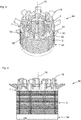
- Fig. 1 shows a first embodiment of a stator 30 of a DC motor with a first embodiment of an insulating material body 7 in a first assembly state, in which the stator 30 is already wound with a winding wire 10.
- the stator 30 consists of a stator core 3 made of layered laminations and in the present example has nine poles 4 which, starting from a return ring 5, extend radially inwards in the direction of a motor longitudinal axis 19. Between each pole 4, a wire connection 18 is made radially beyond the outer diameter of the stator core 3 and the insulating material body 7, the wire connection having an axial component and therefore being inclined by a helix angle in the direction of a winding head.
- the helix angle is selected so that a needle winding machine achieves the shortest possible cycle time and process-reliable installation is possible.
- An insulation cap is also shown on the opposite axial side of the stator core.
- the insulating material body has axially projecting guides 54.
- Fig. 2 shows a sectional view of the DC motor with superimposition of the first assembly state. Shown is the stator 30 with the insulating material body 7, installed in a motor housing 15. A permanent magnetic inner rotor 2 is located opposite the poles 4. In the installed state, the wire connections 18 are in reality no longer in the assembled state Fig. 1 , but lie inside the motor housing. To illustrate the geometrical relationships during the winding process, the wire connections 18 are shown in a radial position.
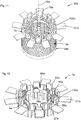
- Fig. 3 shows the stator 30 with a superposition of the first with a second assembly state.
- the wires are out of the Fig. 1 Known position shown and in addition a second layer, which occurs after a bending process, the wire connections 18 extending substantially axially parallel over the winding head 43 away from the stator core.
- the insulating material body 7 has axially projecting contours 56 which are interrupted by slots 55 through which the wire connections 18 can move during the winding process and when bending back.
- the wire connections 18 consist of a first leg 51, a second leg 52 and a contact section 20.
- the first leg 51 is an extension of an end turn of a first pole 4.
- An extension of the second leg 52 forms an initial turn of an adjacent pole.
- the stator core 3 and the insulation cap 34 and the motor longitudinal axis 19 are also shown.
- Fig. 4 shows a front view of the stator 30 with the superimposed first and second assembly state according to Fig. 3 , with the insulating body 7, the stator core 3, the insulation cap 34, the wire connections 18 and the motor longitudinal axis.
- Fig. 5 shows the stator 30 in a second assembly state, in which the wire connections 18 are bent into an essentially axially parallel position.
- the slots 55 in the axially projecting contours 56 of the insulating body 7 no longer have a function in this state.
- the wire connections 18 are prepared for the assembly of a contact unit and have exposed and very easily accessible areas for contacting the process reliably (contact section 20).
- the length of the legs 51, 52 is dimensioned accordingly.
- the contact section 20 is straight in its central section and can thus be used over a large area as a contact surface.
- the stator core 3 the motor longitudinal axis 19 and the insulating cap 34 are shown.
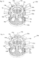
- Fig. 6 shows the stator 30 in a third assembly state, with the insulation cap 34, the motor longitudinal axis, the stator core 3, the insulating body 7, wire connections 18 and a contact unit 16, consisting of three busbars 14, each with three contact projections 13, on which contact hooks 17 are formed, which are each connected to a wire connection 18, in particular to a contact section 20.
- the open side of the contact hook 17 points to the stator core 3.
- Each busbar 14 is connected to a connecting pin 57 which projects axially parallel from the busbar 14.
- the busbars 14 are kept isolated from one another on a contact carrier 58.
- the busbars 14 have radial extensions 59 with which they are centered in the insulating body 7 and secured against rotation.
- the contact carrier 58 is axially seated on the insulating body 7 via axial stops 44.
- Fig. 7 shows the stator 30 in the first assembly state with deflection means 60 fixed to the tool. Two deflection means 60 are assigned to each wire connection 18.
- Fig. 8 shows a variant of the stator 30c with auxiliary formations 61c which can be removed from the workpiece, with deflection pins 62c and detachable connecting means 63c.
- the auxiliary formations 61c are an integral part of an insulating body 7c.
- the insulating cap 34 and the stator core 3c can also be seen.
- the auxiliary formations 61c have recesses which serve to receive tool-fixed support means.
- Fig. 9 shows a further variant of the stator 30d with a combination of tool-fixed deflection means (not shown) and removable auxiliary formations 61d.
- the auxiliary formations 61d extend obliquely outwards from an insulating material body 7d with which they are integral, with an axial and a radial component.
- the auxiliary formations 61d end in an L-shaped support profile 90d with a radial arm 91d and an axial arm 92d.
- the auxiliary formations 61d, in particular the support profiles 90d serve as a support for a wire connection 18d.
- Free spaces 97d can be seen on both sides of the auxiliary formation 61d, which were formed by guiding the winding wire around the deflection means fixed to the tool (not shown here) and then withdrawing the deflection means.
- One of the auxiliary formations 61x has a start stop pin 98d, an end stop pin 99d, a start wire support 93d and an end wire support 94d.
- the auxiliary formation and the stop pin are integral with one another by means of two L-shaped arms 102d.
- a start wire 95d extends obliquely outwards at a different angle than the end wire 96d. As a result, the end wires are at a distance from one another, which makes it easier to cut off the winding wire.
- auxiliary formations 61d are sheared off before the stator 30d is pressed into a motor housing.
- Wire connections 18d, contact sections 20d, a motor longitudinal axis 19d, a stator core 3d and an insulation cap 34d are shown.
- Fig. 10 shows a further view of the stator according to Fig. 6 .
- the first leg 51 of the wire connection 18 extends axially from a stator groove, merges into the contact section 20 and further into the second leg 52, which leads axially back into the same stator groove.
- the busbar 14 is in one piece with the contact projection 13 and the contact hook 17.
- the contact section 20 of the wire connection 18 is received in the contact hook 17 and forms an electrical contact with the contact hook.
- the stator core 3 is shown, which has clamping tongues 31, with the aid of which it can clamp itself in the motor housing (not shown here).
- Fig. 11 shows a second embodiment of a stator 30a, with an insulation cap 34a, a stator core 3a, an insulating body 7a, wire connections 18a, a motor longitudinal axis 19a and cover tabs 101a, which are integral with the insulating body 7a via film hinges 100a.
- the cover flaps 101a are angled to the longitudinal axis 19a of the motor. In the present example, the angle is approximately 90 °.
- the wire connections 18a are shown in the bent-back state.
- Fig. 12 shows a second embodiment of an insulating body 7a as a single component.
- this has a stator groove lining 29a per pole, with grooves 27a, a return ring cover 8a, the cover flaps 101a, the film hinges 100a, guides 54a, contours 56a and slots 55a.
- the winding wire is bent radially outward (see also Fig. 19 ).
- Fig. 13 shows the stator 30a of the second embodiment in a second assembly state, with the insulation cap 34a, the stator core 3a, the insulating body 7a, the cover flap 101a, the film hinges 100a, the wire connections 18a, the motor longitudinal axis 19a and a contact unit 16a, with busbars 14a, contact projections 13a, contact hooks 17a, a contact carrier 58a with axial stops 44a, which abut protruding contours 56a, and connecting pins 57a.
- the cover flaps 101a are arranged such that they form a cover and insulation for the wire connections 18a and the contact hooks 17a after a folding process. Their width is selected so that they fit exactly between guides 54a which project axially from the yoke ring cover 8a.
- Fig. 14 shows the stator 30a, the second embodiment in a third assembly state.
- annular insulation crown 53a consisting of a cover ring 64a and axially projecting crown feet 63a
- Crown feet 63a are in the guides 54a (see Fig. 12 ) introduced. These are dimensioned such that they do not protrude radially beyond the stator core 3a.
- insulation cap 34a the contact unit 16a, the contact hooks, the wire connections 18a, the connecting pins 57a, the cover tabs 101a and the film hinges 100a.
- Fig. 15 shows the stator 30a of the second embodiment in a fourth assembly state.
- the cover flaps 101a are folded down and plunge into the space between the guides 54a, so that they do not have a radial effect.
- Fig. 16 shows an alternative insulation crown 53b, with a cover ring 64b and cover flap 101b.
- the insulation crown 53b is provided after the pressing a stator to be placed in a motor housing on the stator, the cover tabs being arranged between the contact hooks of a contact unit and the motor housing.
- Guide projections 80b are arranged between the cover flaps and are provided for engagement in guides of an insulating material body.
- the insulation crown 53b also serves as a catcher of chips that can arise when the stator is pressed in.
- Fig. 17 shows the stator 30a of the second embodiment in a fourth assembly state in which it is installed in a motor housing 15a.
- the insulating material body 7a, the contact unit 16a, the busbars 14a, the wire connections 18a, the contact hooks 17a, the guides 54a, the slots 55a and the cover flaps 101a are also shown.
- Fig. 18 shows a sectional view of a DC motor 1a with the stator 30a of the second embodiment mounted in the motor housing 15a, with a coil 39a, the stator core 3a, the yoke ring 5a, the inner rotor 2a, the insulating body 7a, the contact unit 16a, the pole 4a, the busbar 14a , the contact hook 17a, the contact carrier 58a, the contact section 20a of the wire connection 18a, the cover tab 101a, the film hinge 100a, the insulation crown 53a, with the cover ring 64a and an attachment 65a, which closes the motor housing 15a.
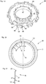
- Fig. 19 shows a contact carrier 58 which is ring-shaped in its basic form, the cross-sectional shape of which is U-shaped to a first approximation, with an inner edge 47, an outer edge 48 and a base 46.
- the area between the inner edge 47, the outer edge 48 and the base serves as a receiving space for the busbars (here not shown).
- Wire stop faces 45 are arranged on the outer edge 48.
- the wire stop surfaces 45 each have an outer edge 69, around which the winding wire is bent.
- a radially outwardly projecting axial stop 44 is arranged between two wire stop surfaces.
- Fig. 20 shows a representation of the position of a reference circle 50 about the motor longitudinal axis 16, the radius of which through the center line of an axially extending winding wire 10 with the radially extremely possible position within the windable winding space of a stator groove 6 is defined.
- Stator 30 with stator core 3 and poles 4 is also shown. Two further dashed circles indicate that the wire connections can only be sensibly arranged in a limited area.
- Fig. 21 shows a wire connection 18, starting from a winding wire 10 of a coil, the first leg 51 is first bent radially outward at a bending point 66 and then radially outward at a second bending point 67.
- a contact section 20 is indicated.
- the second leg, not shown, is designed analogously.
Landscapes
- Engineering & Computer Science (AREA)
- Power Engineering (AREA)
- Manufacturing & Machinery (AREA)
- Insulation, Fastening Of Motor, Generator Windings (AREA)
- Manufacture Of Motors, Generators (AREA)
Applications Claiming Priority (1)
| Application Number | Priority Date | Filing Date | Title |
|---|---|---|---|
| DE102018217857.7A DE102018217857B4 (de) | 2018-10-18 | 2018-10-18 | Gleichstrommotor und Verfahren zu seiner Herstellung |
Publications (3)
| Publication Number | Publication Date |
|---|---|
| EP3641105A1 true EP3641105A1 (fr) | 2020-04-22 |
| EP3641105B1 EP3641105B1 (fr) | 2023-09-20 |
| EP3641105C0 EP3641105C0 (fr) | 2023-09-20 |
Family
ID=68136228
Family Applications (1)
| Application Number | Title | Priority Date | Filing Date |
|---|---|---|---|
| EP19201048.6A Active EP3641105B1 (fr) | 2018-10-18 | 2019-10-02 | Moteur à courant continu et son procédé de fabrication |
Country Status (3)
| Country | Link |
|---|---|
| EP (1) | EP3641105B1 (fr) |
| CN (1) | CN111082575B (fr) |
| DE (1) | DE102018217857B4 (fr) |
Cited By (4)
| Publication number | Priority date | Publication date | Assignee | Title |
|---|---|---|---|---|
| EP3764512A1 (fr) * | 2019-07-10 | 2021-01-13 | Bühler Motor GmbH | Stator d'un moteur électrique et son procédé de fabrication |
| CN114744840A (zh) * | 2022-04-12 | 2022-07-12 | 中特科技工业(青岛)有限公司 | 一种高满槽率定子的绕线机及其绕线方法 |
| WO2022243422A1 (fr) * | 2021-05-21 | 2022-11-24 | Brose Fahrzeugteile SE & Co. Kommanditgesellschaft, Würzburg | Procédé pour former un enroulement de stator, stator en tôle pleine et moteur électrique |
| US11837935B2 (en) | 2021-02-02 | 2023-12-05 | Black & Decker, Inc. | Canned brushless motor |
Families Citing this family (4)
| Publication number | Priority date | Publication date | Assignee | Title |
|---|---|---|---|---|
| IL289207B1 (en) | 2019-06-28 | 2026-04-01 | Abiomed Inc | Intravascular blood pump with multi-layered coreless coils |
| CN113890214A (zh) * | 2020-07-02 | 2022-01-04 | 铜陵硬核派科技有限公司 | 电机定子绕组缠绕方法、绕组模块、铁芯和轴向磁通电机 |
| DE102021205244A1 (de) | 2021-05-21 | 2022-11-24 | Brose Fahrzeugteile SE & Co. Kommanditgesellschaft, Würzburg | Verfahren zur Ausbildung einer Statorwicklung, Vollblechstator und Elektromotor |
| DE102023207302A1 (de) * | 2023-07-31 | 2025-02-06 | Brose Fahrzeugteile SE & Co. Kommanditgesellschaft, Würzburg | Stator für einen Elektromotor |
Citations (5)
| Publication number | Priority date | Publication date | Assignee | Title |
|---|---|---|---|---|
| US20130270932A1 (en) * | 2010-06-14 | 2013-10-17 | Black & Decker Inc. | Rotor assembly for brushless motor for a power tool |
| US20150137637A1 (en) * | 2013-11-20 | 2015-05-21 | New Motech Co., Ltd. | Stator of motor having bus-bar wiring structure and method of wiring coil in parallel using the same |
| DE102015211836A1 (de) * | 2015-06-25 | 2016-12-29 | Robert Bosch Gmbh | Verfahren zum Bewickeln eines Stators, sowie ein Stator und eine elektrische Maschine beinhaltend einen solchen Stator |
| EP3151389A2 (fr) * | 2015-09-30 | 2017-04-05 | Aisin Seiki Kabushiki Kaisha | Machine rotative électrique |
| US20180262075A1 (en) * | 2015-01-07 | 2018-09-13 | Robert Bosch Gmbh | Interconnection board of a stator for an electrical machine and method for producing same |
Family Cites Families (7)
| Publication number | Priority date | Publication date | Assignee | Title |
|---|---|---|---|---|
| CN101694954B (zh) * | 2006-07-04 | 2012-07-25 | 本田技研工业株式会社 | 电动机的定子结构 |
| DE102012010234A1 (de) * | 2012-05-24 | 2013-11-28 | Brose Fahrzeugteile GmbH & Co. Kommanditgesellschaft, Würzburg | Statorsystem für einen Elektromotor |
| KR101992687B1 (ko) * | 2012-06-28 | 2019-06-25 | 엘지이노텍 주식회사 | 모터 |
| WO2016024554A1 (fr) * | 2014-08-11 | 2016-02-18 | アイシン・エィ・ダブリュ株式会社 | Procédé de fabrication de stator et stator |
| DE102015200095B4 (de) * | 2015-01-07 | 2026-03-19 | Robert Bosch Gmbh | Stator für eine elektrische Maschine und Verfahren zum Herstellen eines solchen |
| CN204615524U (zh) * | 2015-04-28 | 2015-09-02 | 中山大洋电机制造有限公司 | 一种外转子电机的塑封定子及其应用的外转子电机 |
| WO2018180816A1 (fr) * | 2017-03-31 | 2018-10-04 | 日本電産株式会社 | Unité de barre omnibus et moteur |
-
2018
- 2018-10-18 DE DE102018217857.7A patent/DE102018217857B4/de active Active
-
2019
- 2019-10-02 EP EP19201048.6A patent/EP3641105B1/fr active Active
- 2019-10-15 CN CN201910976533.6A patent/CN111082575B/zh active Active
Patent Citations (5)
| Publication number | Priority date | Publication date | Assignee | Title |
|---|---|---|---|---|
| US20130270932A1 (en) * | 2010-06-14 | 2013-10-17 | Black & Decker Inc. | Rotor assembly for brushless motor for a power tool |
| US20150137637A1 (en) * | 2013-11-20 | 2015-05-21 | New Motech Co., Ltd. | Stator of motor having bus-bar wiring structure and method of wiring coil in parallel using the same |
| US20180262075A1 (en) * | 2015-01-07 | 2018-09-13 | Robert Bosch Gmbh | Interconnection board of a stator for an electrical machine and method for producing same |
| DE102015211836A1 (de) * | 2015-06-25 | 2016-12-29 | Robert Bosch Gmbh | Verfahren zum Bewickeln eines Stators, sowie ein Stator und eine elektrische Maschine beinhaltend einen solchen Stator |
| EP3151389A2 (fr) * | 2015-09-30 | 2017-04-05 | Aisin Seiki Kabushiki Kaisha | Machine rotative électrique |
Cited By (9)
| Publication number | Priority date | Publication date | Assignee | Title |
|---|---|---|---|---|
| EP3764512A1 (fr) * | 2019-07-10 | 2021-01-13 | Bühler Motor GmbH | Stator d'un moteur électrique et son procédé de fabrication |
| US11837935B2 (en) | 2021-02-02 | 2023-12-05 | Black & Decker, Inc. | Canned brushless motor |
| US11855521B2 (en) | 2021-02-02 | 2023-12-26 | Black & Decker, Inc. | Brushless DC motor for a body-grip power tool |
| US11870316B2 (en) | 2021-02-02 | 2024-01-09 | Black & Decker, Inc. | Brushless motor including a nested bearing bridge |
| US11876424B2 (en) | 2021-02-02 | 2024-01-16 | Black & Decker Inc. | Compact brushless motor including in-line terminals |
| US11955863B2 (en) | 2021-02-02 | 2024-04-09 | Black & Decker Inc. | Circuit board assembly for compact brushless motor |
| US12261497B2 (en) | 2021-02-02 | 2025-03-25 | Black & Decker Inc. | High-power motor for a body-grip power tool |
| WO2022243422A1 (fr) * | 2021-05-21 | 2022-11-24 | Brose Fahrzeugteile SE & Co. Kommanditgesellschaft, Würzburg | Procédé pour former un enroulement de stator, stator en tôle pleine et moteur électrique |
| CN114744840A (zh) * | 2022-04-12 | 2022-07-12 | 中特科技工业(青岛)有限公司 | 一种高满槽率定子的绕线机及其绕线方法 |
Also Published As
| Publication number | Publication date |
|---|---|
| DE102018217857A1 (de) | 2020-04-23 |
| CN111082575B (zh) | 2022-05-27 |
| DE102018217857B4 (de) | 2022-02-03 |
| CN111082575A (zh) | 2020-04-28 |
| EP3641105B1 (fr) | 2023-09-20 |
| EP3641105C0 (fr) | 2023-09-20 |
Similar Documents
| Publication | Publication Date | Title |
|---|---|---|
| EP3641105B1 (fr) | Moteur à courant continu et son procédé de fabrication | |
| DE19920127C2 (de) | Stator für eine elektrische Maschine und Verfahren zur Herstellung eines Stators | |
| DE10152006B4 (de) | Stator für eine elektrische Maschine | |
| DE2211184C3 (de) | Scheibenanker | |
| DE102009016990A1 (de) | Stator, Motor und Verfahren zur Herstellung eines Stators | |
| DE102005001705A1 (de) | Verfahren zur Herstellung von Ankern, Verfahren zur Herstellung von Elektromotoren sowie Anker | |
| EP1748534A2 (fr) | Stator pour moteurs électriques comprenant un système d'interconnexion d'enroulement | |
| DE10056555A1 (de) | Stator für dynamo-elektrische Maschinen | |
| DE112004001908T5 (de) | Anker einer sich drehenden elektrischen Maschine und deren Herstellverfahren | |
| DE102008022170A1 (de) | Spule für eine elektrische Maschine und Herstellungsverfahren für eine Spule | |
| DE102015200095A1 (de) | Stator für eine elektrische Maschine und Verfahren zum Herstellen eines solchen | |
| DE102009045551A1 (de) | Stator für eine elektrische Maschine mit einer Verschaltungseinrichtung | |
| WO2019155278A1 (fr) | Porte-fil | |
| EP3292590B1 (fr) | Procédé de fabrication d'un stator et moteur à courant continu à commutation électronique | |
| DE102019219181A1 (de) | Rotor mit optimierter Festigkeit | |
| DE202008016729U1 (de) | Stator für einen Innenläufermotor | |
| DE102019004591A1 (de) | Elektromotor mit einer Verschaltungseinheit und Verfahren zur Herstellung eines Elektromotors mit einer Verschaltungseinheit | |
| WO2019170751A1 (fr) | Agencement de stator pourvu d'agencement d'enroulement | |
| EP3641104B1 (fr) | Moteur à courant continu et procédé de fabrication d'un moteur à courant continu | |
| DE102018125834A1 (de) | Stator für eine elektrische Maschine und Verfahren zum Herstellen eines derartigen Stators | |
| DE112016003902T5 (de) | Verfahren zur Herstellung eines Ankers und Anker | |
| DE102005000643A1 (de) | Statoranordnung für eine elektrische Maschine | |
| DE102019004589A1 (de) | Elektromotor mit einer Verschaltungseinheit und Verfahren zur Herstellung eines Elektromotors mit einer Verschaltungseinheit | |
| DE102011075575A1 (de) | Stator für eine Elektromaschine mit gekröpften Schweißfahnen zum Anschluss von Spulen | |
| DE102018125838A1 (de) | Stator für eine elektrische Maschine und Verfahren zum Herstellen eines derartigen Stators |
Legal Events
| Date | Code | Title | Description |
|---|---|---|---|
| PUAI | Public reference made under article 153(3) epc to a published international application that has entered the european phase |
Free format text: ORIGINAL CODE: 0009012 |
|
| STAA | Information on the status of an ep patent application or granted ep patent |
Free format text: STATUS: THE APPLICATION HAS BEEN PUBLISHED |
|
| AK | Designated contracting states |
Kind code of ref document: A1 Designated state(s): AL AT BE BG CH CY CZ DE DK EE ES FI FR GB GR HR HU IE IS IT LI LT LU LV MC MK MT NL NO PL PT RO RS SE SI SK SM TR |
|
| AX | Request for extension of the european patent |
Extension state: BA ME |
|
| STAA | Information on the status of an ep patent application or granted ep patent |
Free format text: STATUS: REQUEST FOR EXAMINATION WAS MADE |
|
| 17P | Request for examination filed |
Effective date: 20201022 |
|
| RBV | Designated contracting states (corrected) |
Designated state(s): AL AT BE BG CH CY CZ DE DK EE ES FI FR GB GR HR HU IE IS IT LI LT LU LV MC MK MT NL NO PL PT RO RS SE SI SK SM TR |
|
| STAA | Information on the status of an ep patent application or granted ep patent |
Free format text: STATUS: EXAMINATION IS IN PROGRESS |
|
| 17Q | First examination report despatched |
Effective date: 20210126 |
|
| GRAP | Despatch of communication of intention to grant a patent |
Free format text: ORIGINAL CODE: EPIDOSNIGR1 |
|
| STAA | Information on the status of an ep patent application or granted ep patent |
Free format text: STATUS: GRANT OF PATENT IS INTENDED |
|
| INTG | Intention to grant announced |
Effective date: 20230428 |
|
| GRAS | Grant fee paid |
Free format text: ORIGINAL CODE: EPIDOSNIGR3 |
|
| GRAA | (expected) grant |
Free format text: ORIGINAL CODE: 0009210 |
|
| STAA | Information on the status of an ep patent application or granted ep patent |
Free format text: STATUS: THE PATENT HAS BEEN GRANTED |
|
| AK | Designated contracting states |
Kind code of ref document: B1 Designated state(s): AL AT BE BG CH CY CZ DE DK EE ES FI FR GB GR HR HU IE IS IT LI LT LU LV MC MK MT NL NO PL PT RO RS SE SI SK SM TR |
|
| REG | Reference to a national code |
Ref country code: GB Ref legal event code: FG4D Free format text: NOT ENGLISH |
|
| REG | Reference to a national code |
Ref country code: CH Ref legal event code: EP |
|
| REG | Reference to a national code |
Ref country code: DE Ref legal event code: R096 Ref document number: 502019009404 Country of ref document: DE |
|
| REG | Reference to a national code |
Ref country code: IE Ref legal event code: FG4D Free format text: LANGUAGE OF EP DOCUMENT: GERMAN |
|
| U01 | Request for unitary effect filed |
Effective date: 20230928 |
|
| U07 | Unitary effect registered |
Designated state(s): AT BE BG DE DK EE FI FR IT LT LU LV MT NL PT SE SI Effective date: 20231205 |
|
| PG25 | Lapsed in a contracting state [announced via postgrant information from national office to epo] |
Ref country code: GR Free format text: LAPSE BECAUSE OF FAILURE TO SUBMIT A TRANSLATION OF THE DESCRIPTION OR TO PAY THE FEE WITHIN THE PRESCRIBED TIME-LIMIT Effective date: 20231221 |
|
| PG25 | Lapsed in a contracting state [announced via postgrant information from national office to epo] |
Ref country code: RS Free format text: LAPSE BECAUSE OF FAILURE TO SUBMIT A TRANSLATION OF THE DESCRIPTION OR TO PAY THE FEE WITHIN THE PRESCRIBED TIME-LIMIT Effective date: 20230920 Ref country code: NO Free format text: LAPSE BECAUSE OF FAILURE TO SUBMIT A TRANSLATION OF THE DESCRIPTION OR TO PAY THE FEE WITHIN THE PRESCRIBED TIME-LIMIT Effective date: 20231220 Ref country code: HR Free format text: LAPSE BECAUSE OF FAILURE TO SUBMIT A TRANSLATION OF THE DESCRIPTION OR TO PAY THE FEE WITHIN THE PRESCRIBED TIME-LIMIT Effective date: 20230920 Ref country code: GR Free format text: LAPSE BECAUSE OF FAILURE TO SUBMIT A TRANSLATION OF THE DESCRIPTION OR TO PAY THE FEE WITHIN THE PRESCRIBED TIME-LIMIT Effective date: 20231221 |
|
| U20 | Renewal fee for the european patent with unitary effect paid |
Year of fee payment: 5 Effective date: 20240125 |
|
| PG25 | Lapsed in a contracting state [announced via postgrant information from national office to epo] |
Ref country code: IS Free format text: LAPSE BECAUSE OF FAILURE TO SUBMIT A TRANSLATION OF THE DESCRIPTION OR TO PAY THE FEE WITHIN THE PRESCRIBED TIME-LIMIT Effective date: 20240120 |
|
| PG25 | Lapsed in a contracting state [announced via postgrant information from national office to epo] |
Ref country code: ES Free format text: LAPSE BECAUSE OF FAILURE TO SUBMIT A TRANSLATION OF THE DESCRIPTION OR TO PAY THE FEE WITHIN THE PRESCRIBED TIME-LIMIT Effective date: 20230920 |
|
| PG25 | Lapsed in a contracting state [announced via postgrant information from national office to epo] |
Ref country code: SM Free format text: LAPSE BECAUSE OF FAILURE TO SUBMIT A TRANSLATION OF THE DESCRIPTION OR TO PAY THE FEE WITHIN THE PRESCRIBED TIME-LIMIT Effective date: 20230920 Ref country code: RO Free format text: LAPSE BECAUSE OF FAILURE TO SUBMIT A TRANSLATION OF THE DESCRIPTION OR TO PAY THE FEE WITHIN THE PRESCRIBED TIME-LIMIT Effective date: 20230920 Ref country code: IS Free format text: LAPSE BECAUSE OF FAILURE TO SUBMIT A TRANSLATION OF THE DESCRIPTION OR TO PAY THE FEE WITHIN THE PRESCRIBED TIME-LIMIT Effective date: 20240120 Ref country code: ES Free format text: LAPSE BECAUSE OF FAILURE TO SUBMIT A TRANSLATION OF THE DESCRIPTION OR TO PAY THE FEE WITHIN THE PRESCRIBED TIME-LIMIT Effective date: 20230920 Ref country code: CZ Free format text: LAPSE BECAUSE OF FAILURE TO SUBMIT A TRANSLATION OF THE DESCRIPTION OR TO PAY THE FEE WITHIN THE PRESCRIBED TIME-LIMIT Effective date: 20230920 Ref country code: SK Free format text: LAPSE BECAUSE OF FAILURE TO SUBMIT A TRANSLATION OF THE DESCRIPTION OR TO PAY THE FEE WITHIN THE PRESCRIBED TIME-LIMIT Effective date: 20230920 |
|
| PG25 | Lapsed in a contracting state [announced via postgrant information from national office to epo] |
Ref country code: PL Free format text: LAPSE BECAUSE OF FAILURE TO SUBMIT A TRANSLATION OF THE DESCRIPTION OR TO PAY THE FEE WITHIN THE PRESCRIBED TIME-LIMIT Effective date: 20230920 |
|
| REG | Reference to a national code |
Ref country code: CH Ref legal event code: PL |
|
| REG | Reference to a national code |
Ref country code: DE Ref legal event code: R097 Ref document number: 502019009404 Country of ref document: DE |
|
| PG25 | Lapsed in a contracting state [announced via postgrant information from national office to epo] |
Ref country code: MC Free format text: LAPSE BECAUSE OF FAILURE TO SUBMIT A TRANSLATION OF THE DESCRIPTION OR TO PAY THE FEE WITHIN THE PRESCRIBED TIME-LIMIT Effective date: 20230920 |
|
| PG25 | Lapsed in a contracting state [announced via postgrant information from national office to epo] |
Ref country code: CH Free format text: LAPSE BECAUSE OF NON-PAYMENT OF DUE FEES Effective date: 20231031 |
|
| PLBE | No opposition filed within time limit |
Free format text: ORIGINAL CODE: 0009261 |
|
| STAA | Information on the status of an ep patent application or granted ep patent |
Free format text: STATUS: NO OPPOSITION FILED WITHIN TIME LIMIT |
|
| PG25 | Lapsed in a contracting state [announced via postgrant information from national office to epo] |
Ref country code: MC Free format text: LAPSE BECAUSE OF FAILURE TO SUBMIT A TRANSLATION OF THE DESCRIPTION OR TO PAY THE FEE WITHIN THE PRESCRIBED TIME-LIMIT Effective date: 20230920 Ref country code: CH Free format text: LAPSE BECAUSE OF NON-PAYMENT OF DUE FEES Effective date: 20231031 |
|
| 26N | No opposition filed |
Effective date: 20240621 |
|
| GBPC | Gb: european patent ceased through non-payment of renewal fee |
Effective date: 20231220 |
|
| PG25 | Lapsed in a contracting state [announced via postgrant information from national office to epo] |
Ref country code: IE Free format text: LAPSE BECAUSE OF NON-PAYMENT OF DUE FEES Effective date: 20231002 |
|
| PG25 | Lapsed in a contracting state [announced via postgrant information from national office to epo] |
Ref country code: GB Free format text: LAPSE BECAUSE OF NON-PAYMENT OF DUE FEES Effective date: 20231220 |
|
| PG25 | Lapsed in a contracting state [announced via postgrant information from national office to epo] |
Ref country code: IE Free format text: LAPSE BECAUSE OF NON-PAYMENT OF DUE FEES Effective date: 20231002 Ref country code: GB Free format text: LAPSE BECAUSE OF NON-PAYMENT OF DUE FEES Effective date: 20231220 |
|
| U20 | Renewal fee for the european patent with unitary effect paid |
Year of fee payment: 6 Effective date: 20241018 |
|
| PG25 | Lapsed in a contracting state [announced via postgrant information from national office to epo] |
Ref country code: CY Free format text: LAPSE BECAUSE OF FAILURE TO SUBMIT A TRANSLATION OF THE DESCRIPTION OR TO PAY THE FEE WITHIN THE PRESCRIBED TIME-LIMIT; INVALID AB INITIO Effective date: 20191002 |
|
| PG25 | Lapsed in a contracting state [announced via postgrant information from national office to epo] |
Ref country code: HU Free format text: LAPSE BECAUSE OF FAILURE TO SUBMIT A TRANSLATION OF THE DESCRIPTION OR TO PAY THE FEE WITHIN THE PRESCRIBED TIME-LIMIT; INVALID AB INITIO Effective date: 20191002 |
|
| U20 | Renewal fee for the european patent with unitary effect paid |
Year of fee payment: 7 Effective date: 20251016 |
|
| PG25 | Lapsed in a contracting state [announced via postgrant information from national office to epo] |
Ref country code: TR Free format text: LAPSE BECAUSE OF FAILURE TO SUBMIT A TRANSLATION OF THE DESCRIPTION OR TO PAY THE FEE WITHIN THE PRESCRIBED TIME-LIMIT Effective date: 20230920 |