EP3641418A1 - Procédé d'envoi et de détermination d'informations de rythme, appareil, support de stockage, et processeur - Google Patents
Procédé d'envoi et de détermination d'informations de rythme, appareil, support de stockage, et processeur Download PDFInfo
- Publication number
- EP3641418A1 EP3641418A1 EP18818022.8A EP18818022A EP3641418A1 EP 3641418 A1 EP3641418 A1 EP 3641418A1 EP 18818022 A EP18818022 A EP 18818022A EP 3641418 A1 EP3641418 A1 EP 3641418A1
- Authority
- EP
- European Patent Office
- Prior art keywords
- pbch
- dmrs
- timing information
- sequence
- synchronization signal
- Prior art date
- Legal status (The legal status is an assumption and is not a legal conclusion. Google has not performed a legal analysis and makes no representation as to the accuracy of the status listed.)
- Granted
Links
Images




Classifications
-
- H—ELECTRICITY
- H04—ELECTRIC COMMUNICATION TECHNIQUE
- H04L—TRANSMISSION OF DIGITAL INFORMATION, e.g. TELEGRAPHIC COMMUNICATION
- H04L5/00—Arrangements affording multiple use of the transmission path
- H04L5/003—Arrangements for allocating sub-channels of the transmission path
- H04L5/0048—Allocation of pilot signals, i.e. of signals known to the receiver
- H04L5/0051—Allocation of pilot signals, i.e. of signals known to the receiver of dedicated pilots, i.e. pilots destined for a single user or terminal
-
- H—ELECTRICITY
- H04—ELECTRIC COMMUNICATION TECHNIQUE
- H04W—WIRELESS COMMUNICATION NETWORKS
- H04W56/00—Synchronisation arrangements
- H04W56/001—Synchronization between nodes
- H04W56/0015—Synchronization between nodes one node acting as a reference for the others
-
- H—ELECTRICITY
- H04—ELECTRIC COMMUNICATION TECHNIQUE
- H04J—MULTIPLEX COMMUNICATION
- H04J11/00—Orthogonal multiplex systems, e.g. using WALSH codes
- H04J11/0069—Cell search, i.e. determining cell identity [cell-ID]
- H04J11/0079—Acquisition of downlink reference signals, e.g. detection of cell-ID
-
- H—ELECTRICITY
- H04—ELECTRIC COMMUNICATION TECHNIQUE
- H04L—TRANSMISSION OF DIGITAL INFORMATION, e.g. TELEGRAPHIC COMMUNICATION
- H04L5/00—Arrangements affording multiple use of the transmission path
-
- H—ELECTRICITY
- H04—ELECTRIC COMMUNICATION TECHNIQUE
- H04L—TRANSMISSION OF DIGITAL INFORMATION, e.g. TELEGRAPHIC COMMUNICATION
- H04L5/00—Arrangements affording multiple use of the transmission path
- H04L5/003—Arrangements for allocating sub-channels of the transmission path
- H04L5/0053—Allocation of signalling, i.e. of overhead other than pilot signals
-
- H—ELECTRICITY
- H04—ELECTRIC COMMUNICATION TECHNIQUE
- H04L—TRANSMISSION OF DIGITAL INFORMATION, e.g. TELEGRAPHIC COMMUNICATION
- H04L5/00—Arrangements affording multiple use of the transmission path
- H04L5/02—Channels characterised by the type of signal
- H04L5/06—Channels characterised by the type of signal the signals being represented by different frequencies
- H04L5/10—Channels characterised by the type of signal the signals being represented by different frequencies with dynamo-electric generation of carriers; with mechanical filters or demodulators
-
- H—ELECTRICITY
- H04—ELECTRIC COMMUNICATION TECHNIQUE
- H04W—WIRELESS COMMUNICATION NETWORKS
- H04W56/00—Synchronisation arrangements
- H04W56/001—Synchronization between nodes
-
- H—ELECTRICITY
- H04—ELECTRIC COMMUNICATION TECHNIQUE
- H04W—WIRELESS COMMUNICATION NETWORKS
- H04W72/00—Local resource management
- H04W72/04—Wireless resource allocation
-
- H—ELECTRICITY
- H04—ELECTRIC COMMUNICATION TECHNIQUE
- H04W—WIRELESS COMMUNICATION NETWORKS
- H04W72/00—Local resource management
- H04W72/04—Wireless resource allocation
- H04W72/044—Wireless resource allocation based on the type of the allocated resource
- H04W72/0446—Resources in time domain, e.g. slots or frames
-
- H—ELECTRICITY
- H04—ELECTRIC COMMUNICATION TECHNIQUE
- H04W—WIRELESS COMMUNICATION NETWORKS
- H04W72/00—Local resource management
- H04W72/20—Control channels or signalling for resource management
- H04W72/23—Control channels or signalling for resource management in the downlink direction of a wireless link, i.e. towards a terminal
-
- H—ELECTRICITY
- H04—ELECTRIC COMMUNICATION TECHNIQUE
- H04W—WIRELESS COMMUNICATION NETWORKS
- H04W72/00—Local resource management
- H04W72/30—Resource management for broadcast services
Definitions
- the present invention relates to the field of communications, and in particular to a method and apparatus for transmitting and determining timing information, a storage medium, and a processor.
- PBCH physical broadcast channel
- RV redundancy version
- CRC mask cyclic redundancy check mask
- the terminal needs to report a measurement result corresponding to an SS block index. If the index needs to be obtained by decoding the PBCH, the terminal needs to further receive the PBCH on the measured neighbor cell, which will bring huge overhead to the terminal.
- a carrier frequency higher than that used in fourth-generation (4G) communication systems such as 28 GHz, 45 GHz, 70 GHz, etc.
- 4G fourth-generation
- high-frequency channel has disadvantages of large free propagation losses, easy absorption by oxygen, and great influence from rain attenuation, seriously affecting coverage performance of high-frequency communication systems.
- a carrier frequency corresponding to high-frequency communication has a shorter wavelength, it is possible to ensure that more antenna elements can be accommodated per unit area, and more antenna elements mean that a beam-forming method may be used to improve an antenna gain, thereby ensuring the coverage performance of the high frequency communication.
- a transmitting end can concentrate transmitting energy in a certain direction, and energy is small or absent in other directions, that is, each beam has its own directivity, and each beam can only cover a terminal in a certain direction, and the transmitting end, that is, a base station, needs to transmit a beam in dozens or even hundreds of directions to complete full coverage.
- measurement and identification of a preliminary beam direction are tend to be performed during an initial access of a terminal to a network, and transmit beams at a base station side are swept once in a time interval for the terminal to measure and identify a preferred beam or port.
- FIG. 1 is a structural diagram of a synchronization signal burst set (SS burst set) in the related art.
- this structure is a sweeping resource for transmitting a synchronization signal and a physical broadcast channel, where the SS burst set includes one or more synchronization signal bursts (SS bursts), one SS burst includes one or more synchronization signal blocks (SS blocks), each SS block carries a synchronization signal in a specific beam, a specific port or a specific port set, and once the SS burst set completes sweeping of the beam, all beam transmissions or all port transmissions are completed.
- the SS block may further include a PBCH, a demodulation reference signal corresponding to the PBCH, other control channels, a data channel, and other signals.
- PBCH is recommended to indicate timing information.
- implicit indication by PBCH is a potential method, that is, a different PBCH processing manner (for example, redundancy version (RV), scrambling code, cyclic redundancy check mask (CRC mask)) is used in a different synchronization signal block (SS block) to imply index information of the SS block.
- RV redundancy version
- CRC mask cyclic redundancy check mask
- the terminal needs to report a measurement result corresponding to an SS block index. If the index needs to be obtained by decoding the PBCH, the terminal needs to further receive the PBCH on the measured neighbor cell, which will bring huge overhead to the terminal.
- Embodiments of the present invention provide a method and apparatus for transmitting and determining timing information, a storage medium, and a processor, so as to at least solve problems that a terminal has a large overhead and a large capacity requirement in the related art.
- a method for transmitting timing information including: carrying timing information by using a demodulation reference signal (DMRS), where the timing information is used to indicate a terminal to determine a time domain location; and transmitting the DMRS carrying the timing information to the terminal.
- DMRS demodulation reference signal
- a method for determining timing information including: receiving a DMRS transmitted by a base station; and determining timing information carried in the DMRS, where the timing information is used to indicate a terminal to determine a time domain location.
- a method for mapping a coded bit of a physical broadcast channel (PBCH) including: determining the coded bit of the PBCH; and mapping the coded bit of the PBCH to a resource of the PBCH in a predetermined order.
- PBCH physical broadcast channel
- an apparatus for transmitting timing information including: a carrying module, which is configured to carry timing information by using a DMRS, where the timing information is used to indicate a terminal to determine a time domain location; and a transmitting module, which is configured to transmit the DMRS carrying the timing information to the terminal.
- an apparatus for determining timing information including: a receiving module, configured to receive a DMRS transmitted by a base station; and a first determining module, configured to determine timing information carried in the DMRS, where the timing information is used to indicate a terminal to determine a time domain location.
- an apparatus for mapping a coded bit of a PBCH including: a second determining module, configured to determine the coded bit of the PBCH; and a mapping module configured to map the coded bit of the PBCH to a resource of the PBCH in a predetermined order.
- a storage medium including a stored program, where the program executes the method of any of the above during running.
- a processor for executing a program, where the program executes the method of any of the above during running.
- a base station carries timing information by using a DMRS, where the timing information is used to indicate a terminal to determine a time domain location, and the base station transmits the DMRS carrying the timing information to the terminal for indicating the terminal to acquire the timing information according to the DMRS. Therefore, problems of a large terminal overhead and a large capacity requirement existing in the related art could be solved, and effects of cutting down the terminal overhead and reducing the terminal capacity requirement could be achieved.
- FIG. 2 is a block diagram of a hardware structure of a mobile terminal according to an embodiment of the present invention.
- a mobile terminal 20 may include one or more (merely one is shown in FIG. 2 ) processors 202 (the processor 202 may include, but is not limited to, a processing device such as a microprogrammed control unit (MCU) or a field programmable gate array (FPGA)), a memory 204 for storing data, and a transmission device 206 for communication functions.
- MCU microprogrammed control unit
- FPGA field programmable gate array
- FIG. 2 is merely illustrative and does not limit the structure of the above electronic device.
- the mobile terminal 20 may also include more or fewer components than those shown in FIG. 2 , or have a different configuration than that shown in FIG. 2 .
- the memory 204 may be used to store software programs and modules of the application software, such as program instructions/modules corresponding to a method for transmitting timing information in the embodiment of the present invention, and the processor 202 executes various functional applications and data processing by executing the software programs and modules stored in the memory 204, that is, the above method is implemented.
- the memory 204 may include a high speed random access memory and may also include a non-volatile memory, such as one or more magnetic storage devices, a flash memory, or other non-volatile solid state memories.
- the memory 204 may further include a memory remotely located relative to the processor 202, which may be connected to a mobile terminal 10 over a network. Examples of such networks include, but are not limited to, the Internet, intranets, local area networks, mobile communication networks, and combinations thereof.
- the transmission device 206 is configured to receive or transmit data via a network.
- the above specific network example may include a wireless network provided by a communication provider of the mobile terminal 20.
- the transmission device 206 includes a network interface controller (NIC) that may be connected to other network devices through a base station to communicate with the Internet.
- the transmission device 206 may be a radio frequency (RF) module for communicating with the Internet wirelessly.
- NIC network interface controller
- RF radio frequency
- FIG. 3 is a flowchart of transmitting timing information according to an embodiment of the present invention. As shown in FIG. 3 , the flow includes a step S302 and a step S304. In step S302, carrying timing information by using a DMRS, where the timing information is used to indicate a terminal to determine a time domain location. In step S304, transmitting the DMRS carrying the timing information to the terminal.
- step S302 carrying timing information by using a DMRS, where the timing information is used to indicate a terminal to determine a time domain location.
- step S304 transmitting the DMRS carrying the timing information to the terminal.
- a base station carries timing information by using a DMRS, where the timing information is used to indicate a terminal to determine a time domain location; and the DMRS that carries the timing information is transmitted to the terminal, and the terminal is indicated to acquire the timing information according to the DMRS. Therefore, problems of a large terminal overhead and a large capacity requirement existing in the related art could be solved, and effects of cutting down the terminal overhead and reducing the terminal capacity requirement could be achieved.
- an execution body of the above steps may be a base station, but is not limited thereto.
- the determination of a time domain location by the terminal may include the determination of at least one of: subframe timing, slot timing, synchronization signal burst timing, synchronization signal burst set timing, half frame timing, radio frame timing, and a system frame number (SFN).
- SFN system frame number
- the subframe timing refers to a terminal determining a subframe boundary according to timing information
- the slot timing refers to a terminal determining a slot boundary according to timing information
- the synchronization signal burst timing refers to a terminal determining a boundary of a synchronization signal burst according to timing information
- the synchronization signal burst set timing refers to a terminal determines a synchronization signal burst set boundary according to timing information
- the half frame timing refers to a terminal determining a half frame boundary according to timing information, and distinguishing first and second half frames
- the radio frame timing refers to a terminal determining a radio frame boundary according to timing information
- the determination of the system frame number refers to a terminal determining a system frame number according to timing information.
- the timing information includes at least one of: a serial number of a synchronization signal burst set; a serial number of a synchronization signal burst in a synchronization signal burst set; a serial number of a slot in a synchronization signal burst; a serial number of an SS block in a slot; a serial number of an SS block in a synchronization signal burst set; a serial number of an SS block in a synchronization signal burst; a serial number of a slot in a synchronization signal burst set; a synchronization signal block index; N least significant bits of a synchronization signal block index, where N is a positive integer; M most significant bits of a synchronization signal block index, where M is a positive integer; X middle significant bits of a synchronization signal block index, where X is a positive integer; part or all of information of a SFN; radio frame timing information; and half frame timing information.
- the carrying the timing information by using the DMRS includes: carrying the timing information by using at least one of the following attributes of the DMRS: a DMRS sequence; a mapping resource of the DMRS sequence; and an orthogonal sequence used by the DMRS sequence.
- the DMRS sequence includes one of: DMRS sequences commonly mapped to two PBCH symbols; and DMRS sequences mapped to two PBCH symbols respectively. In this embodiment, it is preferable to perform a related operation according to two PBCH symbols, or to perform the above operation according to more than two PBCH symbols.
- the DMRS sequence includes: DMRS sequences commonly mapped to N physical broadcast channel (PBCH) symbols, where N is an integer greater than or equal to 2.
- PBCH physical broadcast channel
- the carrying the timing information by using the DMRS sequence includes one of: presetting a plurality of DMRS sequences and a correspondence relationship between respective DMRS sequences and values of the timing information, and carrying the timing information by using DMRS sequences commonly mapped to two PBCH symbols; and forming a DMRS sequence combination with DMRS sequences mapped to two PBCH symbols, presetting a plurality of DMRS sequence combinations and a correspondence relationship between the respective DMRS sequence combinations and values of the timing information, and carrying the timing information by using the DMRS sequence combination mapped to the two PBCH symbols respectively.
- the preset DMRS sequences and the preset DMRS sequence combinations may be determined in the following manners: defining a plurality of DMRS sequences by commonly mapping one DMRS sequence on two PBCH symbols; and mapping one DMRS sequence on each of two PBCH symbols independently, forming a DMRS sequence combination with DMRS sequences mapped to the two PBCH symbols, and defining a plurality of DMRS sequence combinations.
- carrying the timing information by using a mapping order of the DMRS sequence includes one of: presetting a plurality of mapping orders and a correspondence relationship between different mapping orders and different values of the timing information, and carrying the timing information by using the mapping orders, where the mapping orders refer to orders of mapping DMRS sequences to DMRS time domain resources and/or frequency domain resources on two PBCH symbols; and presetting a plurality of mapping order combinations and a correspondence relationship between different mapping order combinations and values of the timing information, and carrying the timing information by using the mapping order combinations, where the mapping order combinations refer to combinations of orders of mapping DMRS sequences to DMRS time domain resources and/or frequency domain resources on two PBCH symbols respectively.
- the preset mapping orders and the preset DMRS sequence mapping order combinations are determined in the following manners: commonly mapping a DMRS sequence to two PBCH symbols, and defining a plurality of orders of mapping the DMRS sequence to time domain resources and/or frequency domain resources; and independently mapping one DMRS sequence on each of two PBCH symbols, and defining a plurality of orders of mapping the DMRS sequence to time domain resources and/or frequency domain resources of a PBCH symbol.
- carrying the timing information by using the orthogonal sequence used by the DMRS sequence includes: presetting a plurality of orthogonal sequences having lengths correspond to PBCH symbol numbers, where different orthogonal sequences represent different values of the timing information; and mapping processed DMRS sequences to DMRS resources of the two PBCH symbols respectively by using the preset orthogonal sequences, and carrying the timing information by using the processed DMRS sequences.
- the preset orthogonal sequences include at least one of: [1, 1]; and [1, -1].
- processing the two DMRS sequences on the two PBCH symbols by using the preset orthogonal sequences includes one of: multiplying respective elements of a DMRS sequence on a first PBCH symbol by a first element of the orthogonal sequences, and mapping the multiplying results to a DMRS resource element of the first PBCH symbol respectively; and multiplying respective elements of a DMRS sequence on a second PBCH symbol by a second element of the orthogonal sequences, and mapping the multiplying results to DMRS resource elements of the second PBCH symbol respectively; and multiplying respective elements of a DMRS sequence on a first PBCH symbol by a first element of a first orthogonal sequence respectively to obtain a first sequence, multiplying respective elements of a DMRS sequence on a second PBCH symbol by a second element of the first orthogonal sequence to obtain a second sequence, and adding corresponding elements of the first sequence and the second sequence respectively, and mapping the adding results to DMRS resource elements of the first PBCH symbol
- the method further includes: carrying the timing information by using an attribute of the DMRS and an attribute of the PBCH.
- the attribute of the PBCH includes at least one of: bit information carried by the PBCH; a cyclic shift of a coded bit of the PBCH; a scrambling code of the PBCH; and a cyclic redundancy check mask of the PBCH.
- the method further includes: carrying the timing information by using a DMRS sequence and bit information carried by a PBCH.
- carrying the timing information by using the DMRS sequence and the bit information carried by the PBCH includes: when a number of candidate synchronization signal blocks is 64, defining eight different DMRS sequences for indicating three least significant bits of a synchronization signal block index; and introducing three bits of explicit information in PBCH information bits for indicating three most significant bits of a synchronization signal block index.
- the mapping resource of the DMRS sequence includes at least one of: a part of resource elements (REs) in a frequency band outside a synchronization signal in a PBCH symbol to which the DMRS sequence is mapped; a part of REs in a PBCH bandwidth in a PBCH symbol to which the DMRS sequence is mapped; and in a part of PBCH symbols, a part of resource elements (REs) in a frequency band outside a synchronization signal to which the DMRS sequence is mapped; and in remaining PBCH symbols, a part of REs in a PBCH bandwidth to which the DMRS sequence is mapped.
- REs resource elements
- FIG. 4 is a flowchart of a method for determining timing information according to an embodiment of the present invention. As shown in FIG. 4 , the flow includes a step S402 and a step S404.
- step S402 receiving a DMRS transmitted by a base station.
- step S404 determining timing information carried in the DMRS, where the timing information is used to indicate a terminal to determine a time domain location.
- a terminal acquires timing information from a DMRS by receiving the DMRS transmitted by a base station. Therefore, problems of a large terminal overhead and a large capacity requirement existing in the related art could be solved, and effects of cutting down the terminal overhead and reducing the terminal capacity requirement could be achieved.
- an execution body of the above steps may be a terminal, but is not limited thereto.
- the timing information includes at least one of: a serial number of a synchronization signal burst set; a serial number of a synchronization signal burst in a synchronization signal burst set; a serial number of a slot in a synchronization signal burst; a serial number of an SS block in a slot; a serial number of an SS block in a synchronization signal burst set; a serial number of an SS block in a synchronization signal burst; a serial number of a slot in a synchronization signal burst set; a synchronization signal block index; N least significant bits of a synchronization signal block index, where N is a positive integer; M most significant bits of a synchronization signal block index, where M is a positive integer; X middle significant bits of a synchronization signal block index, where X is a positive integer; part or all of information of a system frame number (SFN); radio frame timing information; and half frame timing information.
- SFN system frame
- determining the timing information carried in the DMRS includes: determining the timing information by using at least one of the following attributes of the identified DMRS: a DMRS sequence; a mapping order of the DMRS sequence; and an orthogonal sequence used by the DMRS sequence.
- the DMRS sequence includes one of: DMRS sequences commonly mapped to two PBCH symbols; and DMRS sequences respectively mapped to two PBCH symbols.
- determining the timing information by using the DMRS sequence includes one of: determining the timing information by using DMRS sequences commonly mapped to the two PBCH symbols and a correspondence relationship between preset DMRS sequences and values of the timing information; and determining the timing information by using DMRS sequences respectively mapped to two PBCH symbols and a correspondence relationship between preset DMRS sequence combinations and values of the timing information.
- determining the timing information by using the mapping order of the DMRS sequence includes one of: determining the timing information by using mapping orders of DMRS sequences commonly mapped to two PBCH symbols and a correspondence relationship between preset mapping orders of DMRS sequences and values of the timing information; and determining the timing information by using mapping orders of DMRS sequences independently mapped to two PBCH symbols respectively and a correspondence relationship between preset mapping order combinations of DMRS sequences on respective PBCH symbols and values of the timing information.
- determining the timing information according to the orthogonal sequence used by the DMRS sequence includes: determining the timing information by using orthogonal sequences used by DMRS sequences mapped to two PBCH symbols and a correspondence relationship between preset orthogonal sequences and values of the timing information.
- the preset orthogonal sequences include at least one of: [1, 1]; and [1, -1].
- the two values of the preset orthogonal sequences are preferred embodiments, and other values may also be included.
- FIG. 5 is a flowchart of a method for mapping a coded bit of a PBCH according to an embodiment of the present invention. As shown in FIG. 5 , the flow includes a step S502 and a step S504.
- step S502 determining a coded bit of the PBCH.
- step S504 mapping the coded bit of the PBCH to a resource of the PBCH in a predetermined order.
- an execution body of the above steps may be a base station, but is not limited thereto.
- mapping the coded bit of the PBCH to the resource of the PBCH in the predetermined order includes: mapping the coded bit of the PBCH to the resource of the PBCH corresponding to a synchronization signal bandwidth; and mapping the coded bit of the PBCH to the resource of the PBCH outside a synchronization signal bandwidth.
- mapping the coded bit of the PBCH to the resource of the PBCH in the predetermined order includes: mapping the coded bit of the PBCH to the resource of the PBCH corresponding to a synchronization signal bandwidth of which a time domain location satisfies a first predetermined condition; mapping the coded bit of the PBCH to the resource of the PBCH outside a synchronization signal bandwidth of which a time domain location satisfies a first predetermined condition; mapping the coded bit of the PBCH to the resource of the PBCH corresponding to a synchronization signal bandwidth of which a time domain location satisfies a second predetermined condition; and mapping the coded bit of the PBCH to the resource of the PBCH outside a synchronization signal bandwidth of which a time domain location satisfies a second predetermined condition.
- This embodiment provides a method for transmitting timing information, including the following contents: carrying at least part of timing information by using a physical broadcast channel (PBCH) demodulation reference signal (DMRS).
- PBCH physical broadcast channel
- DMRS demodulation reference signal
- the timing information includes at least one of: a serial number of a synchronization signal burst set; a serial number of a synchronization signal burst in an SS burst set; a serial number of a slot in a synchronization signal burst; a serial number of an SS block in a slot; a serial number of an SS block in an SS burst set; a serial number of an SS block in an SS burst; a serial number of a slot in an SS burst set; N least significant bits of an SS block index (N least significant bits of the synchronization signal block index); M most significant bits of an SS block index (M most significant bits of the synchronization signal block index); X middle significant bits of an SS block index (X middle significant bits of synchronization signal block index); part or all of information of a system frame number (SFN); radio frame timing information; and half frame timing information.
- N least significant bits of an SS block index N least significant bits of the synchronization signal block
- the carrying at least part of timing information by using the physical broadcast channel demodulation reference signal includes: indicating the timing information by using at least one of the following features of the DMRS: a DMRS sequence; a mapping manner of the DMRS sequence; and an orthogonal cover code (OCC) used by a DMRS sequence on different PBCH symbols.
- a DMRS sequence a DMRS sequence
- a mapping manner of the DMRS sequence a mapping manner of the DMRS sequence
- OCC orthogonal cover code
- Indicating the timing information by using the mapping manner of the DMRS sequence includes defining a plurality of orders of mapping the DMRS sequence to time and frequency domain resources, where different mapping orders indicate different values of the timing information.
- Indicating the timing information by using the orthogonal cover code (OCC) used by the DMRS sequence on different PBCH symbols includes defining a plurality of sets of orthogonal cover codes, and processing DMRS sequences on a plurality of PBCH symbols by using the orthogonal cover codes; and indicating different values of the timing information by using the different orthogonal cover codes.
- OCC orthogonal cover code
- the sequence may be combined with the physical broadcast channel transmission manner to indicate a complete synchronization signal index.
- the physical broadcast channel transmission manner includes at least one of: an information bit carried by a physical broadcast channel, a cyclic shift of a physical broadcast channel coded bit, a scrambling code of a physical broadcast channel, and a CRC mask of a physical broadcast channel.
- This embodiment provides a method for mapping a coded bit of a PBCH, and specifically includes the following contents: mapping a coded bit of a PBCH to a PBCH resource in the following order: first mapping the coded bit of the PBCH to a resource corresponding to a synchronization signal bandwidth in a PBCH symbol; and then mapping the coded bit to a resource outside a synchronization signal bandwidth in a PBCH symbol.
- the PBCH coded bit is mapped to a PBCH resource in the following order: a part corresponding to a synchronization signal bandwidth of an earlier PBCH symbol in time domain -> a part outside a synchronization signal bandwidth of an earlier PBCH symbol in time domain -> a part corresponding to a synchronous signal bandwidth of a later PBCH symbol in time domain -> a part outside a synchronization signal bandwidth of a later PBCH symbol in time domain.
- One SS burst set contains one or more SS bursts, one synchronization signal burst contains one or more synchronization signal blocks (SS blocks), each SS block is used for transmitting information in a specific beam direction, and full coverage of an expected coverage range is completed by a synchronization signal burst set.
- a primary synchronization signal (PSS), a secondary synchronization signal SSS), and a PBCH are included in each synchronization signal block.
- PSS primary synchronization signal
- SSS secondary synchronization signal
- PBCH PBCH
- Multiplexing manners 1-4 correspond to cases where synchronization signals and a physical broadcast channel have different bandwidths (typically, a PSS/SSS occupies 144 REs, where REs in which synchronization signal sequence elements are mapped are 127 REs therein, and a PBCH occupies 288 RE).
- Multiplexing manners 5-8 correspond to cases where synchronization signals and a physical broadcast channel have the same bandwidth (typically, a PSS/SSS/PBCH occupies 144 REs, where REs in which synchronization signal sequence elements are mapped are 127 REs therein).
- multiplexing manner 1 is described as an example; for a case where synchronization signals and a physical broadcast channel have the same bandwidth, multiplexing manner 5 is described as an example; and other multiplexing manners are similar thereto.
- mapping resources of a DMRS have the following three types:
- a synchronization signal occupies 144 resource elements REs, but resources in which a synchronization signal sequence is actually mapped are 127 REs in the middle, and eight or nine REs are reserved on both sides as guard bands.
- a bandwidth of a mapped PBCH DMRS may overlap with a bandwidth of a synchronization signal due to presence of a guard band.
- a PBCH DMRS may be mapped at a certain density in each of upper and lower 84 REs. This case is also within this mapping manner. It is also possible to map a PBCH DMRS at a certain density within each of upper and lower 72 REs.
- timing information may be indicated by using a DMRS corresponding to a synchronization signal bandwidth, or timing information may be indicated by using a DMRS over the entire PBCH bandwidth.
- a frequency domain density of the DMRS may be different in a synchronization signal bandwidth and outside a synchronization signal bandwidth.
- the synchronization signal occupies 144 resource elements REs, but resources in which synchronization signal sequences are actually mapped are 127 REs in the middle, and 8 or 9 REs are reserved on both sides as guard bands.
- a synchronization signal is used for channel estimation before DMRS detection.
- a bandwidth of the mapped PBCH DMRS may be smaller than the synchronization signal bandwidth. For example, for a case where a PBCH occupies 288 REs, a PBCH DMRS may be mapped at a certain density in the middle 132 REs (the 132 REs are completely covered by the synchronization signal bandwidth). This case is also within this mapping manner. It is also possible to map the PBCH DMRS at a certain density within the middle 144 REs.
- a DMRS mapped outside a synchronization signal bandwidth of a first PBCH symbol uses a fixed sequence, which functions as channel estimation (without carrying timing information); a DMRS mapped to a full bandwidth of a second PBCH symbol is used to indicate an SBI.
- a DMRS and an SSS on the first PBCH symbol may be used for channel estimation, and used for coherently detecting the DMRS on the second PBCH symbol to improve detection performance of the DMRS, thereby improving performance of timing information indication.
- the DMRS mapped outside the bandwidth of the synchronization signal of the first PBCH symbol may be a PBCH DMRS mapped at a certain density in each of upper and lower 84 REs, or may be a PBCH DMRS mapped at a certain density in each of upper and lower 72 REs.
- a DMRS is mapped to a part of REs within the entire PBCH bandwidth in a symbol of the PBCH.
- a PBCH contains a plurality of symbols, and is typically configured as two PBCH symbols shown in FIG. 6 .
- a DMRS sequence may be defined as a long sequence that is mapped to a designated RE across a plurality of PBCH symbols; or a DMRS sequence is independently mapped to each PBCH symbol.
- This embodiment describes indicating at least part of timing information by using a PBCH DMRS sequence.
- PBCH TTI 80ms, including four SS burst sets with a period of 20ms, each SS burst set contains 64 SS blocks, which are respectively mapped in the first 32 slots of the SS burst set, two SS blocks are mapped in each slot, where first three symbols of a slot are reserved for transmitting downlink control or mini-slots, and last three symbols are reserved for use as a guard period GP, and for transmitting uplink control.
- a 240 kHz 14 symbols slot is taken as an example.
- a manner of mapping an SS block to a data transmission slot and the number of SS blocks included in an SS burst set are only examples. Other structures and the number of SS blocks are not excluded. For different frequency bands, the number of SS blocks, a subcarrier spacing of a signal channel in an SS block, and a mapping structure of a slot time domain may also be different.
- these 64 resources are potential transmission resources of an SS block. In an actual system, a base station may choose to carry the SS block on some or all of the resources. When some resources do not actually transmit the SS block, the corresponding index will also be reserved, which will not affect indexes of other SS blocks, that is, an SS block index and a time domain location corresponding to the index are fixed.
- the solution considers how a base station indicates to a terminal the 64 SS block indexes ⁇ SS block indexes 0 ⁇ 63 ⁇ .
- one PBCH DMRS sequence is mapped to two PBCH symbols, and the order of mapping is fixed.
- the DMRS on the two symbols is mapped to a fixed frequency domain resource (that is, a fixed RE)
- a frequency domain resource of the DMRS may be a predefined frequency domain resource, or a frequency domain resource related to a cell ID, for example, three groups of DMRS frequency domain resources are predefined, the cell ID is modeled as 3, which will result in 0 or 1 or 2, corresponding to a group of DMRS resources, respectively)
- a length of a DMRS sequence that is, an inserted time-frequency domain interval, needs to satisfy a PBCH demodulation performance requirement, and different timing information is indicated here only by different sequences.
- the timing information indicated by using the DMRS sequence is an SS block index.
- 64 different sequences with a length of 96 are obtained (for example, the DMRS sequence may be a pseudo-random sequence PN sequence (such as an M sequence, etc.), an initial state is first defined, and then different cyclic shifts are performed on an initial sequence to obtain sequences, and other sequence types and other sequence generation methods are not limited).
- PN sequence such as an M sequence, etc.
- a base station will carry different PBCH DMRS sequences in different SS blocks, and a mapping relationship between a DMRS sequence and an SS block index is predefined.
- a DMRS sequence 0 corresponds to an SS block index 0 (SBI 0)
- a terminal first detects a synchronization signal of a cell, determines a symbol of a PBCH according to a fixed time domain location relationship between the PBCH symbol and a symbol of the synchronization signal, then determines a cell ID by detecting primary and secondary synchronization signals, and obtains a frequency domain resource set of a DMRS corresponding to the cell ID.
- a correlation detection operation is further performed on a signal received on the fixed DMRS mapping resource by using a local different DMRS sequence, and a local DMRS sequence corresponding to the maximum correlation peak is determined as a DMRS carried in the current SS block, thereby determining a synchronization signal block index.
- This embodiment describes indicating at least part of timing information by using a mapping order of a PBCH DMRS sequence.
- one PBCH TTI 80 ms, and four SS burst sets of 20 ms period are included.
- This embodiment indicates different SS burst sets in a PBCH TTI by using different mapping orders of PBCH DMRS sequences.
- mapping orders of PBCH DMRS sequences are defined, that is, ⁇ order 0, order 1, order 2, order 3 ⁇ (only four mapping order examples are given here, and other mapping orders are not limited thereto), and correspond to four SS burst sets in the PBCH TTI respectively; for example, order 0 corresponds to a first SS burst set in the PBCH TTI, order 1 corresponds to a second SS burst set in the PBCH TTI, and so on. Further, different 20 ms periods are distinguished. For 10 bits of system frame number (SFN) information, values of the eighth and ninth bits can be determined.
- SFN system frame number
- the first seven bits of the SFN may be explicitly carried by a PBCH.
- the last bit of the SFN may be determined by detection of an SS block, that is, all the SS blocks in the SS burst set are centrally configured in the 5 ms time window, and a fixed relative location relationship between the time window and the 20 ms period is predefined, for example, all the SS blocks are within first 5 ms of 20 ms, and when a terminal detects a synchronization signal, it indicates that the current time domain resource is first 10 ms of 20 ms, that is, the last 1 bit of the SFN is determined.
- a base station will determine a mapping order of a PBCH DMRS in each SS block according to the above mapping relationship in different SS burst sets.
- a terminal first detects a synchronization signal of a cell, determines a symbol of a PBCH according to a fixed time domain location relationship between the PBCH symbol and a symbol of the synchronization signal, determines a cell ID by detecting primary and secondary synchronization signals, and obtains a frequency domain resource set of a DMRS corresponding to the cell ID.
- a correlation detection operation is further performed on a signal received on a fixed DMRS mapping resource by using a local different DMRS mapping order, and a DMRS mapping order corresponding to the maximum correlation peak is determined as a mapping order of a DMRS carried in the current SS block, thereby determining that a current SS block belongs to which SS burst set within a PBCH TTI.
- This embodiment describes indicating at least part of timing information by using a PBCH DMRS sequence and a DMRS mapping order collectively.
- a PBCH DMRS sequence 80 ms
- four SS burst sets of 20 ms period are included, each SS burst set contains 64 different SS blocks, and this embodiment uses different PBCH DMRS sequences and DMRS mapping orders to collectively indicate an SS block index within an SS burst set.
- mapping orders of a PBCH DMRS sequence are defined, that is, ⁇ order 0, order 1, order 2, order 3, ..., order 7 ⁇ (only eight mapping order examples are given here, and other mapping orders are not limited thereto).
- eight different DMRS sequences (such as sequence 0 to sequence 7) need to be defined.
- carrying the timing information by using the DMRS includes: when a number of candidate synchronization signal blocks is 4, defining four different DMRS sequences to be in one-to-one correspondence with four synchronization signal blocks; and when a number of candidate synchronization signal blocks is 8, defining eight different DMRS sequences to be in one-to-one correspondence with eight synchronization signal blocks.
- PN sequence such as an M sequence, etc.
- the PBCH DMRS sequences and the DMRS mapping orders collectively indicate SS block indexes, and specific indication relationships are as shown in Table 1.
- Table 1 SS block index PBCH DMRS mapping order PBCH DMRS sequence 0 Order 0 Sequence 0 1 Order 0 Sequence 1 2 Order 0 Sequence 2 3 Order 0 Sequence 3 4 Order 0 Sequence 4 5 Order 0 Sequence 5 6 Order 0 Sequence 6 7 Order 0 Sequence 7 8 Order 1 Sequence 0 9 Order 1 Sequence 1 10 Order 1 Sequence 2 ... ... ... 62 Order 7 Sequence 6 63 Order 7 Sequence 7
- a base station will determine a PBCH DMRS sequence and a mapping order thereof in the SS block according to an SS block index.
- a terminal first detects a synchronization signal of a cell, determines a PBCH symbol according to a fixed time domain location relationship between the PBCH symbol and a symbol of the synchronization signal, determines a cell ID by detecting primary and secondary synchronization signals, and obtains a frequency domain resource set of a DMRS corresponding to the cell ID.
- a correlation detection operation is performed on a signal received on a fixed DMRS mapping resource, and a DMRS mapping order corresponding to the maximum correlation peak is determined as a mapping order and sequence of a DMRS carried in the current SS block, thereby determining a current SS block index.
- This embodiment describes another way to carry at least part of timing information by using PBCH DMRS sequences and/or mapping orders.
- a manner of mapping a DMRS on two PBCH symbols is: a DMRS inserted outside a bandwidth of a synchronization signal of a first PBCH symbol uses a fixed sequence, which functions as channel estimation (without carrying timing information); and a DMRS sequence inserted in a full bandwidth of a second PBCH symbol is used to indicate timing information.
- the DMRS and an SSS on the first PBCH symbol may be used for channel estimation, that is, a part corresponding to the synchronization signal bandwidth may use the synchronization signal for channel estimation, and a part outside the synchronization signal bandwidth may use the DMRS on the first PBCH symbol for channel estimation.
- a coherent detection operation is performed on the DMRS on the second PBCH symbol to improve detection performance of the DMRS, thereby improving performance of timing information indication.
- a manner in which the DMRS on the second PBCH symbol carries the timing information is: defining a plurality of DMRS sequences.
- DMRS is inserted to the second PBCH symbol at a density of 1/3, that is, 96 REs of 288 REs are used to map the DMRS, and eight DMRS sequences with a length of 96 are generated, which are corresponding to different values of the timing information respectively; for example, a SS burst set contains eight SS blocks, and each DMRS sequence corresponds to one SS block index.
- a correspondence relationship as shown in Table 2 are predefined, and a base station transmits a corresponding DMRS sequence in different SS blocks, and a terminal determines a current SS block index by identifying the DMRS sequence on the second PBCH symbol.
- a terminal before identifying the DMRS sequence on the second PBCH symbol, a terminal first uses the synchronization signal and the DMRS on the first PBCH symbol to respectively perform channel estimation for the corresponding frequency band, and uses a channel estimation result, and performs a coherence detection operation on the DMRS on the second PBCH symbols, and the different local sequences are used to correlate with the signals received on the DMRS frequency domain resources, and a sequence with the largest peak is determined as a DMRS sequence transmitted by a current base station.
- the SS block index corresponding to the sequence is the timing information to be identified. Table 2 SS block index DMRS sequence on a second PBCH symbol 0 Sequence 0 1 Sequence 1 2 Sequence 2 3 Sequence 3 4 Sequence 4 5 Sequence 4 6 Sequence 6 7 Sequence 7
- the mapping order of the DMRS sequence on the second PBCH symbol may be introduced to carry more timing information, and two mapping orders of a DMRS sequence on the second PBCH symbol are predefined: mapping from a high RB number to a low RB number, and mapping from a low RB number to a high RB number.
- a combination of a sequence and mapping order of a DMRS may carry more timing information.
- a terminal identifies carried timing information by identifying a sequence and mapping order of a DMRS on a second PBCH symbol.
- This embodiment describes another way to carry at least part of timing information by using a PBCH DMRS sequence.
- a manner of mapping a DMRS on two PBCH symbols includes inserting the DMRS into three parts.
- the DMRS is inserted to a part of REs outside a bandwidth of a synchronization signal of a first PBCH symbol (a DMRS sequence may be mapped to both sides of the bandwidth of the synchronization signal) (referred to as a first DMRS); the DMRS is inserted to a part of REs of a bandwidth corresponding to a bandwidth of a synchronization signal of a first PBCH symbol (referred to as a second DMRS); and the DMRS is inserted to a part of REs of a full bandwidth of a second PBCH symbol (referred to as a third DMRS).
- the first DMRS is a fixed sequence, and the sequence may be a sequence related to a cell identity, that is, different cell IDs may correspond to different sequences, but different synchronization signal blocks of the same cell use the same sequence, and do not carry timing information.
- the second DMRS and the third DMRS may be configured with a plurality of sequences, and a combination of the two sequences is used to carry timing information.
- a length of the first DMRS sequence is 48
- a length of the second DMRS sequence is 48
- a length of the third DMRS sequence is 96.
- the second DMRS pre-defines four DMRS sequences
- the third DMRS pre-defines 16 DMRS sequences
- a sequence combination of the two include 64 states, which may be used to carry 6 bits of timing information.
- an SS burst set contains 64 SS blocks, and a DMRS sequence combination may be used to carry an SS block index.
- a terminal when identifying the second DMRS, uses a synchronization signal for channel estimation, and performs coherent detection on the second DMRS, and uses different local sequences of the second DMRS to be correlated with signals received on the second DMRS frequency domain resource, and determines the currently transmitted second DMRS sequence.
- a terminal uses a synchronization signal and the first DMRS to perform channel estimation respectively, performs a coherent detection operation on the third DMRS by using channel estimation results, and uses different local sequences of the third DMRS to be correlated with signals received on the DMRS frequency domain resource, and determines the obtained sequence with the maximum peak as the third DMRS sequence transmitted by a current base station.
- An SS block index corresponding to a combination of two sequences is the timing information to be identified.
- the timing information is still indicated by the second DMRS and the third DMRS, and different DMRS mapping order combinations are defined, and the DMRS mapping order combinations may also be used to indicate timing information. In other embodiments, the DMRS sequence combinations and the DMRS mapping order combinations may also indicate timing information collectively.
- This embodiment describes another way to carry at least part of timing information by using a PBCH DMRS sequence.
- a manner of mapping a DMRS on two PBCH symbols includes inserting the DMRS into two parts.
- the DMRS is inserted to a part of REs outside a bandwidth of a synchronization signal of a first PBCH symbol (a DMRS sequence may be mapped to both sides of the synchronization signal bandwidth) (referred to as a first DMRS); and the DMRS is inserted to both a part of REs of a bandwidth corresponding to a bandwidth of a synchronization signal of a first PBCH symbol, and a part of REs of the full bandwidth of a second PBCH symbol (referred to as a second DMRS).
- the first DMRS is a fixed sequence and does not carry timing information.
- the second DMRS may be configured with a plurality of sequences, and different sequences are used to carry timing information.
- the first DMRS may be that a PBCH DMRS is mapped at a certain density in each of upper and lower 84 REs, and correspondingly, on a part of REs of a bandwidth corresponding to a bandwidth of the synchronization signal on the first PBCH symbol, specifically mapped to a part of REs of the middle 132 REs; or the first DMRS may be that a PBCH DMRS is mapped at a certain density in each of upper and lower 72 REs, and correspondingly, on a part of REs of a bandwidth corresponding to a bandwidth of the synchronization signal on the first PBCH symbol, and specifically mapped to a part of REs of the middle 144 REs. Both cases are applicable.
- the length of the first DMRS sequence is 48; and the length of the second DMRS sequence is 144.
- the second DMRS is predefined with 16 DMRS sequences and may be used to carry 4 bits of timing information.
- an SS burst set contains 64 SS blocks, and a DMRS sequence combination may be used to carry an SS block index.
- a terminal when a terminal identifies the second DMRS, different parts of the second DMRS sequence utilize different channel estimation results; for example, in the second DMRS, a DMRS mapped to the synchronization signal bandwidth on the first PBCH symbol and the second PBCH symbol uses the synchronization signal for channel estimation; in the second DMRS, a DMRS mapped outside the synchronization signal bandwidth on the second PBCH symbol uses the first DMRS for channel estimation, performs a coherent detection operation on the second DMRS, and determines the sequence used by the second DMRS, thereby determining the value of the timing information.
- An SS block index corresponding to a combination of two sequences is the timing information to be identified.
- the timing information is still indicated by the second DMRS, and a different second DMRS mapping order is defined.
- the second DMRS mapping order may also be used to indicate timing information.
- the second DMRS sequence and the second DMRS mapping order may also indicate timing information collectively.
- This embodiment describes another way to carry at least part of timing information by using a PBCH DMRS sequence and/or a mapping order.
- a manner of mapping a DMRS on two PBCH symbols is: mapping the DMRS on a part of resource elements REs outside a bandwidth of a synchronization signal, and mapping the DMRS outside a bandwidth of a synchronization signal of the first PBCH symbol, using a fixed sequence, which functions as channel estimation (without carrying timing information); and DMRS sequence inserted in a full bandwidth of a second PBCH symbol is used to indicate timing information.
- the DMRS mapped to the second PBCH symbol defines a plurality of sequences, and different sequences are used to indicate different values of the timing information.
- the DMRS on the first PBCH symbol may be used for channel estimation and frequency offset estimation.
- a coherent detection operation is performed on the DMRS on the second PBCH symbol to improve detection performance of the DMRS, thereby improving performance of timing information indication.
- a manner in which the DMRS on the second PBCH symbol carries the timing information is: defining a plurality of DMRS sequences. For example, on the second PBCH symbol, the length of the DMRS sequence is 48, and 16 DMRS sequences with a length of 48 are defined.
- a different mapping order of a DMRS on the second PBCH symbol may be defined, and the DMRS mapping order may also be used to indicate timing information.
- the DMRS sequence and the DMRS mapping order may also indicate timing information collectively.
- two DMRS sequences may be mapped to upper and lower parts of the synchronization signal bandwidth, that is, a DMRS sequence with a length of 24 is defined, and a combination of two sequences is used to indicate timing information.
- a different mapping order combination of a DMRS on the second PBCH symbol may be defined, and the DMRS mapping order combination may also be used to indicate timing information.
- the DMRS sequence combination and the DMRS mapping order combination may also indicate timing information collectively.
- This embodiment describes indicating at least part of timing information by using a PBCH DMRS sequence combination.
- PBCH TTI 80 ms
- eight SS burst sets of 10 ms period are included
- each SS burst set includes four SS blocks that are mapped in the first two slots of the SS burst set respectively, and two SS blocks are mapped in each of the slots, where first three symbols of the slot are reserved for transmitting downlink control or mini-slots, and last three symbols are reserved for use as a guard period GP, and transmission of uplink control.
- a 15 kHz 14 symbols slot is taken as an example.
- a manner of mapping an SS block to a data transmission slot and the number of SS blocks included in an SS burst set are only examples. Other structures and the number of SS blocks are not excluded. For different frequency bands, the number of SS blocks, a subcarrier spacing of a signal channel in an SS block, and a mapping structure of a slot time domain may also be different.
- these four resources are potential transmission resources of an SS block. In an actual system, a base station may choose to carry the SS block on some or all of the resources. When some resources do not actually transmit the SS block, the corresponding index will also be reserved, which will not affect indexes of other SS blocks, that is, an SS block index and a time domain location corresponding to the index are fixed.
- two PBCH DMRS sequences are respectively mapped to two PBCH symbols, and mapping orders are fixed.
- a DMRS on each of the PBCH symbols is mapped to a fixed frequency domain resource (that is, a fixed RE)
- a frequency domain resource of the DMRS may be a predefined frequency domain resource, or a frequency domain resource related to a cell ID, for example, three groups of DMRS frequency domain resources are predefined, the cell ID is modeled as 3, which will result in 0 or 1 or 2, corresponding to a group of DMRS resources, respectively).
- different timing information is indicated only by inserting different sequence combinations of DMRS to two PBCH symbols.
- the DMRS sequence on the first PBCH symbol as an example, eight different sequences with a length of 48 are obtained according to a certain generation method, that is, ⁇ Q0, Q1, Q2, Q3, Q4, Q5, Q6, Q7 ⁇ (for example, the DMRS sequence may be a pseudo-random sequence PN sequence (such as an M sequence, etc.).
- PN sequence such as an M sequence, etc.
- An initial state is first defined, and then different cyclic shifts are performed on an initial sequence to obtain other sequences, and other sequence types and other sequence generation methods are not limited).
- Generation of a DMRS sequence on another PBCH symbol is similar, and four different sequences are obtained, that is, ⁇ S0, S1, S2, S3 ⁇ .
- a base station will carry different PBCH DMRS sequence combinations in different SS blocks, and a mapping relationship between a DMRS sequence combination and ⁇ SS block index, serial number of SS burst set ⁇ is predefined, for example, in the manner shown in Table 3, it is equivalent that a DMRS sequence on the first PBCH symbol indicates a serial number of an SS burst set, and a DMRS sequence on the second PBCH symbol indicates an SS block index.
- a terminal first detects a synchronization signal of a cell, determines a symbol of a PBCH according to a fixed time domain location relationship between a PBCH symbol and a symbol of a synchronization signal, further correlate different local DMRS sequences ⁇ Q0, Q1, Q2, Q3, Q4, Q5, Q6 and Q7 ⁇ and signals received on a fixed DMRS frequency domain mapping resource on the first PBCH symbol, respectively, and determines a local DMRS sequence corresponding to the maximum correlation peak as a DMRS sequence carried on the first PBCH symbol in the current SS block (for example, Q6); and similarly, the terminal correlates different local DMRS sequences ⁇ S0, S1, S2, S3 ⁇ and signals received on a fixed DMRS frequency domain mapping resource on the second PBCH symbol, respectively, and determines a local DMRS sequence corresponding to the maximum correlation peak as a DMRS sequence carried on the second PBCH symbol in the current SS block (for example, S2). Therefore, the detected SS
- This embodiment describes indicating at least part of timing information by using a mapping order combination of a PBCH DMRS sequence.
- one PBCH TTI 80 ms, and four SS burst sets of 20 ms period are included.
- This embodiment uses different mapping orders of PBCH DMRS sequences to indicate different SS burst sets in the PBCH TTI.
- two PBCH DMRS sequences are respectively mapped to two PBCH symbols.
- four mapping order combinations of PBCH DMRS sequences are defined, that is, ⁇ order 0, order 1, order 2, order 3 ⁇ (here merely four mapping order examples are given, and other mapping sequences are not limited thereto), and correspond to four SS burst sets in a PBCH TTI respectively.
- order 0 corresponds to a first SS burst set in the PBCH TTI
- order 1 corresponds to a second SS burst set in the PBCH TTI, and so on.
- different 20 ms periods are distinguished. For 10 bits of system frame number information (SFN), values of the eighth and ninth bits can be determined.
- SFN system frame number information
- the first seven bits of the SFN may be explicitly carried by a PBCH.
- the last bit of the SFN may be determined by the detection of an SS block, that is, all the SS blocks in the SS burst set are centrally configured in the 5 ms time window, and a fixed relative location relationship between the time window and the 20 ms period is predefined, for example, the SS block is within the first 5 ms of 20 ms, and when a terminal detects a synchronization signal, it indicates that the current time domain resource is the first 10 ms of 20 ms, that is, the last 1 bit of the SFN is determined.
- a base station will determine a mapping order of a DMRS on two PBCH symbols in each SS block according to the above mapping relationship in different SS burst sets.
- a terminal first detects a synchronization signal of a cell, and determines a symbol of a PBCH according to a fixed time domain location relationship between a PBCH symbol and a symbol of a synchronization signal, further assumes different DMRS mapping orders, and performs a correlation detection operation on signals received on a fixed DMRS frequency domain mapping resource on the first PBCH symbol by using a local DMRS sequence, and determines a mapping order of a DMRS corresponding to the maximum correlation peak as a mapping order of a DMRS carried on the first PBCH symbol in the current SS block (for example, mapping from a high RB to a low RB), and similarly, assumes different DMRS mapping orders, and performs a correlation detection operation on a signal received on a fixed DMRS frequency domain mapping resource on the second PBCH symbol by using a local DMRS sequence, and determines a mapping order of a DMRS corresponding to the maximum correlation peak as a mapping order of a DMRS carried on
- This embodiment describes indicating at least part of timing information by using an orthogonal sequence on a PBCH DMRS sequence.
- PBCH TTI 80ms
- four SS burst sets with a period of 20ms are included
- each SS burst set includes eight SS blocks that are mapped in the first four slots of the SS burst set respectively, and two SS blocks are mapped in each of the slots, where first three symbols of the slot are reserved for transmitting downlink control or mini-slots, and last three symbols are reserved for use as a guard period GP, and transmission of uplink control.
- a 30 kHz 14 symbols slot is taken as an example.
- a manner of mapping an SS block to a data transmission slot and the number of SS blocks included in an SS burst set are only examples. Other structures and the number of SS blocks are not excluded. For different frequency bands, the number of SS blocks, a subcarrier spacing of a signal channel in an SS block, and a mapping structure of a slot time domain may also be different.
- these eight resources in the SS burst set are potential transmission resources of the SS block.
- a base station may choose to carry an SS block on some or all of the resources. When some resources do not actually transmit the SS block, the corresponding index will also be reserved, which will not affect indexes of other SS blocks, that is, an SS block index and a time domain location corresponding to the index are fixed.
- This embodiment considers how a base station indicates to a terminal the eight SS block indexes ⁇ SS block indexes 0 ⁇ 7 ⁇ .
- two PBCH DMRS sequences are respectively mapped to two PBCH symbols, and mapping orders are fixed.
- a DMRS on each of the PBCH symbols is mapped to a fixed frequency domain resource (that is, a fixed RE)
- a frequency domain resource of the DMRS may be a predefined frequency domain resource, or a frequency domain resource related to a cell ID, for example, three groups of DMRS frequency domain resources are predefined, the cell ID is modeled as 3, which will result in 0 or 1 or 2, corresponding to a group of DMRS resources, respectively).
- a DMRS sequence on the first PBCH symbol may be the same as or different from a DMRS sequence on the second PBCH symbol.
- different timing information is indicated by only inserting different orthogonal sequences used by the DMRS to the two PBCH symbols.
- the DMRS sequences on the two symbols are further subjected to orthogonal cover coding, i.e., processed with an orthogonal cover code.
- orthogonal cover coding i.e., processed with an orthogonal cover code.
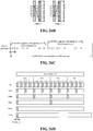
- Eight orthogonal sequences as shown in FIG. 21 are defined, and mapping relationships between an orthogonal sequence combination and an SS block index as shown in Table 4 are predefined.
- Table 4 SS block index Orthogonal cover code 0 [+1, -1], [+1, +1] 1 [-1, +1], [+1, +1] 2 [+1, +1], [+1, -1] 3 [+1, +1], [-1, +1] 4 [-1, -1], [-1, +1] 5 [-1, -1], [+1, -1] 6 [-1, +1], [-1, -1] 7 [+1, -1], [-1, -1]
- each element of a DMRS sequence on a second PBCH symbol is multiplied by a first element of the other of the orthogonal sequences respectively to obtain a sequence P
- each element of a DMRS sequence on a second PBCH symbol is multiplied by a second element of the other of the orthogonal sequences to obtain a sequence Q
- the corresponding elements of the sequence P and the sequence Q are added respectively to obtain ⁇ a0+b0, a1+b1, a2+b2, ... ..., a47+b47 ⁇
- the obtained elements are mapped to DMRS resource elements of the second PBCH symbol respectively.
- DMRS sequences ⁇ a0-b0, a1-b1, a2-b2, ... ..., a47-b47 ⁇ and ⁇ a0+b0, a1+b1, a2+b2, whil , a47+b47 ⁇ are actually carried on the two PBCH symbols, respectively.
- a terminal needs to adopt a specific orthogonal sequence, [+1, +1] and [-1, +1] so that the original DMRS sequence information can be restored.
- a same original sequence is processed by using a different orthogonal sequence combination in Table 3, different actual transmit DMRS sequences are thus obtained, and when the terminal receives the sequences, the different orthogonal sequence combination is used to perform inverse processing on the received DMRS sequences to restore the original DMRS sequence.
- a terminal determines an orthogonal sequence attached to a current DMRS sequence according to an orthogonal sequence used when an original DMRS sequence is successfully restored, and then determines an SS block index.
- This embodiment describes another way of indicating at least part of timing information by using an orthogonal sequence on a PBCH DMRS sequence.
- PBCH TTI 80 ms
- four SS burst sets with a period of 20ms are included
- each SS burst set includes eight SS blocks that are mapped in first four slots of the SS burst set respectively, and two SS blocks are mapped in each of the slots, where first three symbols of the slot are reserved for transmitting downlink control or mini-slots, and last three symbols are reserved for use as a guard period GP, and transmission of uplink control.
- a 30 kHz 14 symbols slot is taken as an example.
- a manner of mapping an SS block to a data transmission slot and the number of SS blocks included in an SS burst set are only examples. Other structures and the number of SS blocks are not excluded. For different frequency bands, the number of SS blocks, a subcarrier spacing of a signal channel in an SS block, and a mapping structure of a slot time domain may also be different.
- these eight resources in the SS burst set are potential transmission resources of an SS block. In an actual system, a base station may choose to carry the SS block on some or all of the resources. When some resources do not actually transmit the SS block, the corresponding index will also be reserved, which will not affect indexes of other SS blocks, that is, an SS block index and a time domain location corresponding to the index are fixed.
- This embodiment describes how a base station indicates to a terminal whether the detected SS block is a first SS block or a last SS block in a slot.
- two PBCH DMRS sequences are respectively mapped to two PBCH symbols, and mapping orders are fixed.
- a DMRS on each of the PBCH symbols is mapped to a fixed frequency domain resource (that is, a fixed RE)
- a frequency domain resource of the DMRS may be a predefined frequency domain resource, or a frequency domain resource related to a cell ID, for example, three groups of DMRS frequency domain resources are predefined, the cell ID is modeled as 3, which will result in 0 or 1 or 2, corresponding to a group of DMRS resources, respectively).
- a DMRS sequence on the first PBCH symbol may be the same as or different from a DMRS sequence on the second PBCH symbol.
- different timing information is indicated by only inserting different orthogonal sequences used by the DMRS on the two PBCH symbols.
- a set of orthogonal sequences [+1, +1] and [+1, -1], is defined.
- an orthogonal sequence [+1, +1] is used on a first SS block of each slot, that is, multiplying respective elements of a DMRS sequence on a first PBCH symbol by a first element of the orthogonal sequence, and mapping the multiplying results to DMRS resource elements of the first PBCH symbol respectively; and multiplying respective elements of a DMRS sequence on a second PBCH symbol by a second element of the orthogonal sequence, and mapping the multiplying results to DMRS resource elements of the second PBCH symbol respectively.
- each element of original DMRS sequences on the two PBCH symbols, ⁇ a0, a1, a2, whil, a47 ⁇ and ⁇ b0, b1, b2, . «, b47 ⁇ is multiplied by +1 respectively; on a last SS block of each slot, an orthogonal sequence [+1, -1] is used for processing, that is, each element of the original DMRS sequence on the first PBCH symbol, ⁇ a0, a1, a2, ...
- a47 ⁇ is multiplied by +1, and each element of the original DMRS sequence on the last PBCH symbol, ⁇ b0, b1, b2, whil, b47 ⁇ , is multiplied by -1 to obtain ⁇ -b0, -b1, -b2, . «, -b47 ⁇ .
- a terminal determines whether a current SS block is a first SS block or a last SS block in a slot by determining an orthogonal sequence used in the current SS block.
- the terminal connects data received in a DMRS frequency domain location within the two PBCH symbols in the order indicated by the arrow (the first symbol is mapped from an RE with a high number to an RE with a low number), and performs correlation computation on received sequences by using the following local sequences respectively, ⁇ a0, a1, a2, ..., a47, b0, b1, b2, ..., b47 ⁇ and ⁇ a0, a1, a2, ..., a47, -b0, -b1, -b2, ..., -b47 ⁇ to obtain two correlation values R1 and R2. If R1>R2, an orthogonal sequence used by a transmitting end is [+1, +1], otherwise an orthogonal sequence used by the transmitting end is [+1, -1].
- This embodiment describes another way to indicate at least part of timing information by using an orthogonal sequence combination on a PBCH DMRS sequence.
- PBCH TTI 80ms
- four SS burst sets with a period of 20ms are included
- each SS burst set includes eight SS blocks that are mapped in the first four slots of the SS burst set respectively, and two SS blocks are mapped in each of the slots, where first three symbols of the slot are reserved for transmitting downlink control or mini-slots, and last three symbols are reserved for use as a guard period GP, and transmission of uplink control.
- This embodiment describes how a base station indicates to a terminal four slots ⁇ Slot 0 ⁇ 3 ⁇ in an SS burst set.
- DMRS sequences of different frequency domain parts adopt different orthogonal sequences.
- an upper half of the DMRS sequences uses an orthogonal sequence 1
- a lower half of the DMRS sequences uses an orthogonal sequence 2.
- a combination of the two indicates timing information collectively.
- a mapping relationship between an orthogonal sequence and a serial number of a slot as shown in Table 5 may also be predefined.
- Table 5 Serial number of slot in SS burst set Orthogonal sequence 1 Orthogonal sequence 0 [+1, +1] [+1, +1] 1 [+1, +1] [+1, -1] 2 [+1, -1] [+1, +1] 3 [+1, -1] [+1, -1]
- DMRSs of upper and lower half of frequency domain parts are respectively processed by using different orthogonal sequences in the same manner as described in Embodiment 11, so as to restore an original DMRS sequence.
- a combination of orthogonal sequences used is identified, and further, an SS block index is determined.
- This embodiment describes indicating at least part of timing information by using a mapping order of a PBCH DMRS sequence and a combination of orthogonal sequences on the PBCH DMRS sequence.
- PBCH TTI 80 ms
- four SS burst sets with a period of 20 ms are included
- each SS burst set includes eight SS blocks that are mapped in first four slots of the SS burst set respectively, and two SS blocks are mapped in each of the slots, where first three symbols of the slot are reserved for transmitting downlink control or mini-slots, and last three symbols are reserved for use as a guard period GP, and transmission of uplink control.
- this embodiment further indicates a serial number of an SS burst set by using mapping orders of different PBCH DMRS sequences. As shown in FIG.
- mapping order combinations of PBCH DMRS sequences are defined, that is, ⁇ order 0, order 1, order 2, order 3 ⁇ (only four mapping order examples are given here, and other mapping orders are not limited thereto), and correspond to four SS burst sets in the PBCH TTI respectively; for example, order 0 corresponds to a first SS burst set in the PBCH TTI, order 1 corresponds to a second SS burst set in the PBCH TTI, and so on.
- a base station will adopt the corresponding DMRS mapping order in a different SS burst set, and process the DMRS by using the corresponding orthogonal sequence for a different SS block.
- DMRS mapping sequences are assumed, and under certain DMRS mapping order assumptions, different orthogonal sequences are used for despreading, and an original sequence of a DMRS is correlated with a despreaded signal of the received signal.
- the terminal uses an orthogonal sequence to obtain the largest correlation peak in a certain DMRS mapping order, a mapping order of a DMRS in a current SS block and an orthogonal sequence used are determined, thereby determining a serial number of an SS burst set and an SS block index that the current SS block belongs to.
- timing information is collectively indicated by a DMRS mapping order and an additional orthogonal sequence
- the method of the present invention is also applicable to other manners of collective indication.
- a collective indication of timing information is performed by using any combination of a DMRS mapping order, an orthogonal sequence, and a DMRS sequence.
- This embodiment describes a method in which a PBCH DMRS sequence is mapped over the entire PBCH bandwidth and a part of the DMRSs corresponding to a synchronization signal bandwidth is used to indicate timing information.
- the PBCH DMRS is mapped over the entire PBCH bandwidth, for the part of DMRSs overlapping with a synchronization signal, since the synchronization signal and the PBCH use the same antenna port, the synchronization signal may be used for channel estimation, frequency offset estimation and compensation, which is more advantageous for utilizing coherent detection of the part of DMRSs to improve detection performance.
- the synchronization signal occupies a bandwidth of 144 RE, where the synchronization signal sequence is mapped to the middle of 127 REs, and each has eight or nine REs as guard bands.
- the PBCH DMRS may be inserted in the bandwidth corresponding to 127 REs, so that channel estimation and frequency offset estimation and compensation may be performed by using synchronization signals (PSS/SSS). It is also possible to insert a PBCH DMRS in the bandwidth corresponding to 144 REs. Although this is slightly different from the synchronization signal, the channel estimation and frequency offset estimation for an edge DMRS RE are not accurate, but are also acceptable.
- PBCH DMRS is inserted with 144 REs and the DMRS inserted in the bandwidth range is used to indicate the timing information.
- a DMRS sequence mapped in a bandwidth corresponding to a synchronization signal bandwidth and a DMRS sequence outside the synchronization signal bandwidth may be independent sequences. As shown in the left (a) of FIG. 25 , a DMRS sequence is commonly mapped to two PBCH symbols in a bandwidth corresponding to the synchronization signal, and a DMRS sequence are commonly mapped to two PBCH symbols outside the synchronization signal bandwidth. It is also possible to map a DMRS sequence within the PBCH bandwidth.
- timing information may be indicated by using a DMRS sequence, a DMRS mapping order, an orthogonal sequence, an orthogonal sequence combination, and a combination of the above.
- a terminal When detecting a DMRS, a terminal completes detection of a synchronization signal, uses synchronization signals to perform channel estimation, frequency offset estimation and compensation, and further performs a correlation operation with the DMRS, thereby determining a DMRS sequence, a mapping order, an orthogonal sequence used, and the like of the corresponding part of the synchronization signal bandwidth in a current PBCH symbol. Specific methods are the same as the previous embodiments, and the timing information corresponding thereto is thus obtained.
- This embodiment describes a method in which a PBCH DMRS sequence is mapped to the entire PBCH bandwidth and timing information is indicated by using a DMRS over the entire PBCH bandwidth.
- the PBCH DMRS is mapped to the entire PBCH bandwidth, and the DMRS on the entire PBCH bandwidth is used to indicate timing information.
- the DMRS sequence length is longer, and more information may be implied; however, since only a part of the bandwidth overlaps with the synchronization signal, using the synchronization signal for channel estimation, frequency offset estimation, and coherent detection for DMRS does not necessarily bring about a gain in detection performance.
- the method does not limit whether a terminal uses a synchronization signal for channel estimation, frequency offset estimation and compensation.
- DMRS sequences may be independently mapped to two symbols, or one DMRS sequence may be commonly mapped thereon.
- timing information may be indicated by using a DMRS sequence, a DMRS mapping order, an orthogonal sequence, an orthogonal sequence combination, and any combination of the above.
- the synchronization signal may be used for channel estimation, frequency offset estimation and compensation (that is, a channel estimation result of the synchronization signal is applied to a part of DMRS corresponding to the bandwidth of the synchronization signal, and a coherent detection operation is performed on this part of the DMRS; and the channel estimation result of the synchronization signal is not applied to the DMRS outside the synchronization signal bandwidth, and a non-coherent detection operation is performed on the part of the DMRS); the channel estimation and the frequency offset estimation and compensation may not be performed at all, and the non-coherent detection operation is performed on the DMRS so as to determine a DMRS sequence, a mapping order, an orthogonal sequence used, and the like in a current PBCH symbol, and the specific manner is the same as the foregoing embodiment, thereby obtaining timing information corresponding thereto.
- timing information is indicated by using a PBCH DMRS sequence and a physical broadcast channel transmission manner collectively.
- the physical broadcast channel transmission manner includes at least one of: information bits carried by a physical broadcast channel, a cyclic shift of physical broadcast channel information bits, a scrambling code of a physical broadcast channel, a CRC mask of a physical broadcast channel, and a redundancy version (RV) of a physical broadcast channel.
- the timing information includes: 10 bits of SFN information, 1 bit of half frame timing, and 6 bits of SS block index information.
- a PBCH TTI is 80 ms, that is, PBCH information content is unchanged within 80 ms, high 7 bits of an SFN may be explicitly carried in a payload of the PBCH.
- the 8th and 9th bits of the SFN (equivalent to distinguishing different SS burst sets in the PBCH TTI) need to achieve timing of a 20 ms level, and an SS burst set may be distinguished by different RVs.
- a terminal mainly detects the SS block, which means that the current SS block is in a first 10 ms of 20 ms (that is, a first radio frame within 20 ms), and located in a first half of the radio frame.
- SS block index information may be carried by using different DMRS sequences in the manner of Embodiment 1.
- the foregoing is merely a typical example of indicating timing information by using a PBCH DMRS sequence and a physical broadcast channel transmission manner.
- the PBCH DMRS sequence and the physical broadcast channel transmission manner may be combined in any manner to indicate complete timing information.
- a method for indicating complete timing information is described, which specifically includes the following contents: a synchronization signal burst set has the following six period configurations, including: 5 ms, 10 ms, 20 ms, 40 ms, 80 ms and 160 ms.
- requirements for the number of indication bits are different.
- a terminal in a 5 ms period configuration, a terminal needs to distinguish 16 potential locations within a 80 ms PBCH TTI, that is, 4 bits indication information is required. For higher period configuration, fewer indication bits are required.
- the same timing indication information should correspond to the same time domain location regardless of the transmission period, in order to avoid timing ambiguity of the terminal.
- combinations of different PBCH RVs (0 to 4), PBCH DMRS mapping orders (order 0, order 1), and PBCH DMRS sequence groups (Sequence group 0, Sequence group 1) correspond to different timing indication information for indicating the lower three bits of a system frame number and half frame timing.
- PBCH DMRS mapping orders order 0, order 1
- PBCH DMRS sequence groups Sequence group 0, Sequence group 1
- the number of SS blocks included in an SS burst set is also different.
- the SS burst set contains up to four SS blocks; in a frequency band of 3 GHz to 6 GHz, an SS burst set contains up to eight SS blocks; and in a frequency band of 6 GHz to 52.6 GHz, an SS burst set contains up to 64 SS blocks. Therefore, the number of SS block indexes in an SS burst set is also different, and the number of required indication bits is also different.
- a DMRS is inserted to a part of REs outside a synchronization signal bandwidth of a first PBCH symbol (a DMRS sequence may be mapped to both sides of the synchronization signal bandwidth) (referred to as a first DMRS); and a DMRS is commonly mapped to both a part of REs of a bandwidth corresponding to a synchronization signal bandwidth of a first PBCH symbol, and a part of REs of the full bandwidth of the second PBCH symbol (referred to as a second DMRS).
- the first DMRS is a fixed sequence, and the sequence may be a sequence related to a cell identity, that is, different cell IDs may correspond to different sequences, but the same sequence is used in different synchronization signal blocks of the same cell, and does not carry timing information.
- the second DMRS may configure a plurality of sequences (such as 32) and introduce different mapping orders (two mapping orders shown by arrows in FIG. 26b ).
- Timing information includes: a 10 bits of SFN, half frame timing, and a 6 bits of SS block index. Indication is given by using the following manners: The high 7 bits of the SFN are used to be explicitly carried in PBCH information bits.
- PBCH information bits As shown in FIG. 26a , four PBCH RVs are defined for indicating 20 ms timing (corresponding to the 8th and 9th bits of the SFN), that is, RV 0 corresponds to a first 20 ms in the PBCH TTI, RV 1 corresponds to a second 20 ms in the PBCH TTI, RV 2 corresponds to a third 20 ms in the PBCH TTI, and RV 3 corresponds to a fourth 20 ms in the PBCH TTI.
- the radio frame timing (equivalent to the lowest bit of the SFN) is indicated by two PBCH DMRS mapping orders, for example, order 0 corresponds to a first radio frame within each 20 ms, and order 2 corresponds to a last radio frame within each 20 ms.
- 32 PBCH DMRS sequences are divided into two groups, each group contains 16 sequences, and a sequence group (SG) to which the currently mapped sequence belongs is used to indicate first and second half frames in a radio frame.
- SG sequence group
- 16 sequences are sufficient to indicate eight SS block indexes. Therefore, for a frequency band below 3 GHz, an SS burst set contains up to four SS blocks, and four different DMRS sequences are defined to be in one-to-one correspondence with the four SS blocks; for a frequency band of 3 GHz to 6 GHz, an SS burst set contains up to eight SS blocks, and eight different DMRS sequences are defined to be in one-to-one correspondence with the eight SS blocks; and for a frequency band above 6 GHz, 16 sequences are not sufficient to indicate 64 different SS block indexes. As shown in FIG. 26c , in PBCH information bits, 2 bits of explicit information are introduced, which are 00, 01, 10 and 11, respectively.
- information bits for indicating an SS block index may not be introduced in the PBCH information bits, and a terminal determines the number of PBCH information bits according to a frequency band range to which an access frequency point belongs. It is also possible to consider to preserve the two bits at the low frequency from the perspective of uniform design, and configure them with the same value (for example, 00, these two bits have no real-time meaning), or two bits corresponding to the low frequency are used to indicate other information, thus maintaining the number of PBCH information bits in high and low frequencies to be the same.
- Timing information includes: a 10 bits of SFN, half frame timing, and a 6 bits of SS block index. Indication is given by using the following manners: 7 high bits of the SFN are used to be explicitly carried in PBCH information bits.
- PBCH RVs are defined for indicating 20 ms timing (corresponding to the 8th and 9th bits of the SFN), that is, RV 0 corresponds to a first 20 ms in a PBCH TTI, RV 1 corresponds to a second 20 ms in the PBCH TTI, RV 2 corresponds to a third 20 ms in the PBCH TTI, and RV 3 corresponds to a fourth 20 ms in the PBCH TTI.
- CRC mask 0 corresponds to a first 5 ms
- CRC mask 1 corresponds to a second 5 ms in 20 ms
- CRC mask 2 corresponds to a third 5 ms in 20 ms
- CRC mask 3 corresponds to a fourth 5 ms in 20 ms.
- RV ⁇ CRC uniquely corresponds to a time domain location to avoid terminal timing ambiguity problems. That is, for the 5 ms of period, different combinations of RV and CRC will be used; and for a larger period, some combinations will not be used. For example, in a 40 ms of period, merely two combinations such as RV0 ⁇ CRC0 and RV2 ⁇ CRC0 are applied.
- carrying the timing information by using the DMRS includes: dividing all defined DMRS sequences into two sequence groups, and a sequence group to which the DMRS sequence belongs being used to indicate first and second half frames in a radio frame. For a frequency band below 6 GHz, eight sequences are sufficient to indicate eight SS block indexes.
- an SS burst set contains up to four SS blocks, and four different DMRS sequences are defined to be in one-to-one correspondence with the four SS blocks; for a frequency band of 3 GHz to 6 GHz, an SS burst set contains up to eight SS blocks, and eight different DMRS sequences are defined to be in one-to-one correspondence with the eight SS blocks; and for a frequency band above 6 GHz, eight sequences are not sufficient to indicate 64 different SS block indexes.
- PBCH information bits 3 bits of explicit information are introduced, which are 000, 001, 010, 011, 100, 101, 110 and 111, respectively. The 3 bits of explicit information is used to indicate three most significant bits of an SS block index. Therefore, a plurality of adjacent SS blocks will contain the same PBCH information bits, facilitating combined reception.
- information bits for indicating an SS block index may not be introduced in the PBCH information bits, and a terminal determines the number of PBCH information bits according to a frequency band range to which an access frequency point belongs. It is also possible to consider to preserve the three bits at the low frequency from the perspective of uniform design, and configure them with the same value (for example, 000, these three bits have no practical meaning), or three bits corresponding to the low frequency are used to indicate other information, thus maintaining the number of PBCH information bits in high and low frequencies to be the same.
- 7 bits of information may be carried by an attribute of a DMRS, for example, being commonly carried by preset 64 DMRS sequences and mapping orders of two DMRS sequences; and for a frequency band of 6 GHz or higher, 8 bits of information may be carried by an attribute of a DMRS, for example, being commonly carried by preset 128 DMRS sequences and mapping orders of two DMRS sequences.
- Timing information includes: a 10 bits of SFN, half frame timing, and a 6 bits of SS block index. Indication is given by using the following manners: 7 high bits of the SFN are used to be explicitly carried in PBCH information bits.
- two PBCH DMRS mapping orders (Order 0, Order 1) as shown in FIG. 26b are defined, which are used to indicate 40 ms timing, that is, first and second 40 ms in 80 ms PBCH TTI are distinguished (corresponding to the 8th bit of the SFN). That is, Order 0 corresponds to a first 40 ms in the PBCH TTI, and Order 1 corresponds to a second 40 ms in the PBCH TTI.
- each SS burst set contains up to 8 SS blocks, and then contains up to 8 SS burst sets in 40 ms (corresponding to the case of a 5 ms of period), and therefore there are up to 64 SS blocks in 40 ms.
- 64 sequences (sequence 0 to sequence 63) included in a DMRS are in one-to-one correspondence with 64 SS blocks in 40 ms. When the period is greater than 5 ms, only a part of DMRS sequences will be used.
- each SS burst set contains up to 64 SS blocks, and up to 8 SS burst sets are contained in 40 ms.
- 128 sequences included in a DMRS are not sufficient to be divided into two groups ⁇ sequence 0 to sequence 63 ⁇ and ⁇ sequence 64 to sequence 127 ⁇ for indicating 20ms timing, that is, using a sequence group ⁇ sequence 0 to sequence 63 ⁇ for a first 20 ms within each 40 ms, each sequence corresponding to an SS block index within an SS burst set; and using a sequence group ⁇ sequence 64 to sequence 127 ⁇ for a second 20 ms within each 40 ms, each sequence corresponding to an SS block index within an SS burst set (burst set).
- Different 5 ms within 40ms are carried by an attribute of a PBCH, for example, defining eight different scrambling bits of PBCH coded bits to correspond to different 5 ms within 40ms respectively.
- 3 bits of timing information is carried in a payload of the PBCH for indicating locations of eight different 5 ms.
- bits for indicating timing information may not be introduced in the PBCH information bits, and a terminal determines the number of PBCH information bits according to a frequency band range to which an access frequency point belongs. It is also possible to consider to preserve the three bits at the low frequency from the perspective of uniform design, and configure them with the same value (for example, 000, these three bits have no real-time meaning), or three bits corresponding to the low frequency are used to indicate other information, thus maintaining the number of PBCH information bits in high and low frequencies to be the same.
- a DMRS for a frequency band below 6 GHz, 5 bits of information may be carried by an attribute of a DMRS, for example, being commonly carried by preset 16 DMRS sequences and mapping orders of two DMRS sequences; and for a frequency band of 6 GHz or higher, 8 bits of information may be carried by an attribute of a DMRS, for example, being commonly carried by preset 128 DMRS sequences and mapping orders of two DMRS sequences.
- Timing information includes: a 10 bits of SFN, half frame timing, and a 6 bits of SS block index. Indication is given by using the following manners: 7 high bits of the SFN are used to be explicitly carried in PBCH information bits.
- PBCH RVs are defined for indicating 20 ms timing (corresponding to the 8th and 9th bits of the SFN), that is, RV 0 corresponds to a first 20 ms in the PBCH TTI, RV 1 corresponds to a second 20 ms in the PBCH TTI, RV 2 corresponds to a third 20 ms in the PBCH TTI, and RV 3 corresponds to a fourth 20 ms in the PBCH TTI.
- Radio frame timing that is, first and second 10 ms within each 20 ms, is indicated by a mapping order of a PBCH. That is, Order 0 corresponds to a first 10 ms within 20 ms, and Order 1 corresponds to a second 10 ms within 20 ms.
- a sequence is divided into two groups, and a sequence in each sequence group (SG) indicates first and second half frame; for a frequency band below 6 GHz, each SG contains 8 sequences; and for a frequency band above 6 GHz, each SG contains 64 sequences; that is, SG 0 corresponds to a first 5 ms in each radio frame, and SG 1 corresponds to a second 5 ms in each radio frame.
- RV ⁇ Order ⁇ CRC uniquely corresponds to a time domain location to avoid terminal timing ambiguity problems. That is, for a 5 ms of period, different combinations of RV ⁇ Order ⁇ SG will be used; and for a larger period, some combinations will not be used. For example, in a 40 ms of period, only two combinations such as RV 0 ⁇ Order 0 ⁇ SG 0 and RV 2 ⁇ Order 0 ⁇ SG 0 are applied.
- an SS burst set contains up to four SS blocks, and four different DMRS sequences are defined to be in one-to-one correspondence with the four SS blocks; for a frequency band of 3 GHz to 6 GHz, an SS burst set contains up to eight SS blocks, and a correspondence relationship between eight different DMRS sequences and eight SS blocks are preset, and the corresponding DMRS sequences are mapped in a specified mapping order (mapping order) in a specified SS block; and for a frequency band above 6 GHz, 64 sequences are used to indicate 64 SS block indexes, and a correspondence relationship between 64 different DMRS sequences and 64 SS blocks are preset, and the corresponding DMRS sequences are mapped in a specified mapping order in a specified SS block.
- different PBCH DMRS sequences may indicate SS block indexes within a radio frame range. That is, for a frequency band below 6 GHz, 16 different PBCH DMRS sequences correspond to 16 SS blocks respectively in a radio frame (up to two SS burst sets, each SS burst set contains at most eight SS blocks). For a frequency band above 6 GHz, 128 different PBCH DMRS sequences correspond to 128 SS blocks in a radio frame respectively (containing up to two SS burst sets, each of which contains up to 64 SS blocks).
- mapping manner of a PBCH coded bit is described.
- the synchronization signal may be used for channel estimation of the PBCH of the corresponding bandwidth, and for the PBCH bandwidth outside the synchronization signal, according to the manner described in the foregoing embodiments of the present invention, since a PBCH DMRS sequence needs to indicate timing information, a terminal needs to perform blind check on a DMRS sequence, or a mapping order, or an orthogonal sequence, which will take a certain amount of time. As shown in FIG. 27 , a PBCH coded bit is mapped in an order indicated by arrows shown in FIG.
- the corresponding resources in the synchronization signal bandwidth may include complete PBCH coded bit, and the PBCH coded bit is repeatedly transmitted on a PBCH resource outside the synchronization signal bandwidth.
- the terminal under the condition of high SNR can complete reception of the PBCH by decoding only the PBCH in a part corresponding to the synchronization signal bandwidth.
- the two parts of the PBCH coded bits inside and outside the synchronization signal bandwidth may be combined and decoded.
- the two parts of the PBCH coded bits may not be simply repeated, but use different redundancy versions to support the terminal to perform incremental redundancy (IR) combinations on the two parts of the PBCH coded bits.
- a resource corresponding to a bandwidth of a synchronization signal merely includes a part of the PBCH coded bit, and the complete PBCH coded bit is included on all the PBCH resources.
- the same PBCH information of the two parts may be used for frequency offset estimation. Therefore, the PBCH may be encoded according to a resource in a bandwidth corresponding to a bandwidth of the synchronization signal of a single PBCH symbol, and repeatedly transmitted on the corresponding bandwidth of a synchronization signal of another PBCH symbol, that is, within the corresponding bandwidth of the synchronization signal of a certain PBCH symbol, complete PBCH coded bit information is included.
- a terminal under the condition of a high SNR can complete reception of a PBCH by decoding a received signal in the corresponding bandwidth of a synchronization signal of a certain PBCH symbol.
- two repeated PBCH coded bits will enable frequency offset estimation.
- transmission of the PBCH coded bit may be repeated twice at an approximate code rate, or the PBCH coded bit may be repeatedly transmitted at a lower code rate.
- a mapping manner of a PBCH is described. Since a synchronization signal and a PBCH use the same antenna port, the synchronization signal may be used for channel estimation of the PBCH of the corresponding bandwidth, and for a PBCH bandwidth outside the synchronization signal, according to the manner described in Embodiments 3-9 of the present invention, since a PBCH DMRS sequence needs to indicate timing information, a terminal needs to perform blind check on a DMRS sequence, or a mapping order, or an OCC, which will take a certain amount of time. In addition, the preceding PBCH symbols allow for earlier decoding.
- the PBCH coded bit is mapped in an order indicated by arrows in FIG. 28 , that is, a part corresponding to a synchronization signal bandwidth of a PBCH symbol of which a time domain location is placed at the front -> a part outside a synchronization signal bandwidth of a PBCH symbol of which a time domain location is placed at the front -> a part corresponding to a synchronous signal bandwidth of a PBCH symbol of which a time domain location is placed at the back -> a part outside a synchronization signal bandwidth of a PBCH symbol of which a time domain location is placed at the back.
- a resource of a part corresponding to a synchronization signal bandwidth is mapped first, and then a resource of a part outside the synchronization signal bandwidth is mapped. This allows a terminal to start decoding a PBCH coded bit of the part corresponding to the synchronization signal bandwidth after successfully detecting the synchronization signal, and proceed to decode a PBCH coded bit outside the synchronization signal bandwidth after successfully identifying a PBCH DMRS and using the DMRS to complete channel estimation.
- each PBCH symbol may include a complete PBCH coded bit, and the PBCH coded bit is repeatedly transmitted on another PBCH symbol.
- a terminal under the condition of a high SNR can complete reception of a PBCH by only decoding a PBCH in a part corresponding to a synchronization signal bandwidth.
- the two parts of the PBCH coded bits inside and outside the synchronization signal bandwidth may be combined and decoded.
- the two parts of the PBCH coded bits may not be simply repeated, but use different redundancy versions to support the terminal to perform incremental redundancy (IR) combinations on the two parts of the PBCH coded bits.
- the resource corresponding to the synchronization signal bandwidth may include a complete PBCH coded bit, and the PBCH coded bit is repeatedly transmitted on a PBCH resource outside the synchronization signal bandwidth.
- a terminal under the condition of a high SNR can decode the PBCH by only decoding the PBCH corresponding to the synchronization signal bandwidth. If the decoding cannot be successfully performed, the two parts of the PBCH coded bits inside and outside the synchronization signal bandwidth may be combined and decoded. The two parts of the PBCH coded bits may not be simply repeated, but use different redundancy versions to support the terminal to perform incremental redundancy combinations on the two parts of the PBCH coded bits.
- a resource corresponding to a synchronization signal bandwidth only include a part of PBCH coded bit, and the complete PBCH coded bits is included on all the PBCH resources.
- a PBCH may be encoded according to a resource corresponding to a synchronization signal bandwidth of a single PBCH symbol, and repeatedly transmitted on the corresponding bandwidth of a synchronization signal of another PBCH symbol, that is, within a bandwidth corresponding to a synchronization signal bandwidth of a certain PBCH symbol, complete PBCH coded bit information is included.
- a terminal under the condition of a high SNR can complete reception of a PBCH by decoding a received signal in the corresponding bandwidth of a synchronization signal of a certain PBCH symbol.
- two repeated PBCH coded bits will enable frequency offset estimation.
- transmission of the PBCH coded bit may be repeated twice at an approximate code rate, or the PBCH coded bit may be repeatedly transmitted at a lower code rate.
- the present solution provides a method for indicating timing information by using a PBCH DMRS sequence, a mapping order, an OCC, and any combination. Therefore, when complete SS block index information is indicated by using a sequence, decoding of a PBCH in a terminal measurement and reporting process can be avoided; if it is finally determined that the terminal still needs to obtain the index by decoding the PBCH, complexity of the blind detection of the PBCH is also minimized to the greatest extent, and part of the information is considered to be obtained before the PBCH is checked, that is, the part of information is indicated by the sequence.
- the method described in the application effectively reduces capacity requirement for a single indication manner.
- the present invention also provides a manner of mapping a coded bit of a PBCH, which could decode the PBCH more quickly, and supports reception of the PBCH by a terminal with small bandwidth capability very well.
- the embodiment further provides an apparatus for transmitting timing information, and the apparatus is configured to implement the foregoing embodiment and preferable implementation manners, and what has been illustrated will not repeated redundantly.
- the term "module" may implement a combination of software and/or hardware with a predetermined function.
- the apparatus described in the following embodiment is preferably implemented by software, the implementation of hardware or a combination of software and hardware is also possible and conceivable.
- FIG. 29 is a structural block diagram of an apparatus for transmitting timing information according to an embodiment of the present invention.
- the apparatus includes: a carrying module 2902 and a transmitting module 2904.
- the carrying module 2902 is configured to carry timing information by using a DMRS, where the timing information is used to indicate a terminal to determine a time domain location
- the transmitting module 2904 is connected to the carrying module 2902, and configured to transmit the DMRS carrying the timing information to the terminal.
- the timing information includes at least: a serial number of a synchronization signal burst set; a serial number of a synchronization signal burst in a synchronization signal burst set; a serial number of a slot in a synchronization signal burst; a serial number of an SS block in a slot; a serial number of an SS block in a synchronization signal burst set; a serial number of an SS block in a synchronization signal burst; a serial number of a slot in a synchronization signal burst set; a synchronization signal block index; N least significant bits of a synchronization signal block index, where N is a positive integer; M most significant bits of a synchronization signal block index, where M is a positive integer; X middle significant bits of a synchronization signal block index, where X is a positive integer; part or all of information of a system frame number (SFN); radio frame timing information; or half frame timing information.
- SFN system frame number
- the carrying module 2902 carries the timing information by using the DMRS in the following manners: carrying the timing information by using at least one of the following attributes of the DMRS: a DMRS sequence; a mapping resource of the DMRS sequence; or an orthogonal sequence used by the DMRS sequence.
- the DMRS sequence includes one of: DMRS sequences commonly mapped to two PBCH symbols; and DMRS sequences respectively mapped to two PBCH symbols.
- the carrying module 2902 carries the timing information by using the DMRS in one of the following manners: presetting a plurality of the DMRS sequences and a correspondence relationship between the respective DMRS sequences and values of the timing information, and carrying the timing information by using DMRS sequences commonly mapped to two PBCH symbols; or DMRS sequences mapped to two PBCH symbols forming a DMRS sequence combination, presetting a plurality of DMRS sequence combinations and a correspondence relationship between the respective DMRS sequence combinations and values of the timing information, and carrying the timing information by using the DMRS sequence combination mapped to the two PBCH symbols respectively.
- the apparatus carries the timing information by using the mapping order of the DMRS sequence in one of the following manners: presetting a plurality of mapping orders and a correspondence relationship between different mapping orders and different values of the timing information, and carrying the timing information by using the mapping orders, where the mapping orders refer to orders of mapping DMRS sequences to DMRS time domain resources and/or frequency domain resources on two PBCH symbols; or presetting a plurality of mapping order combinations and a correspondence relationship between different mapping order combinations and values of the timing information, and carrying the timing information by using the mapping order combinations, where the mapping order combinations refer to combinations of orders of mapping DMRS sequences to DMRS time domain resources and/or frequency domain resources on two PBCH symbols respectively.
- the apparatus uses the orthogonal sequence used by the DMRS sequence to carry the timing information in one of the following manners: presetting a plurality of orthogonal sequences having lengths correspond to PBCH symbol numbers, where different orthogonal sequences represent different values of the timing information; and mapping the processed DMRS sequences to DMRS resources of the two PBCH symbols respectively by using the preset orthogonal sequences, and carrying the timing information by using the processed DMRS sequences.
- the preset orthogonal sequences include at least one of: [1, 1]; and [1, -1].
- the apparatus processes the two DMRS sequences on the two PBCH symbols by using the preset orthogonal sequences in one of the following manners: multiplying respective elements of a DMRS sequence on a first PBCH symbol by a first element of the orthogonal sequences, and mapping the multiplying results to DMRS resource elements of the first PBCH symbol respectively; and multiplying respective elements of a DMRS sequence on a second PBCH symbol by a second element of the orthogonal sequences, and mapping the multiplying results to DMRS resource elements of the second PBCH symbol respectively; or multiplying respective elements of a DMRS sequence on a first PBCH symbol by a first element of a first orthogonal sequence to obtain a first sequence, multiplying respective elements of a DMRS sequence on a second PBCH symbol by a second element of the first orthogonal sequence to obtain a second sequence, and adding corresponding elements of the first sequence and the second sequence respectively, and mapping the adding results to DMRS resource elements of the first PBCH symbols by
- the apparatus further includes a processing module configured to carry the timing information by using an attribute of the DMRS and an attribute of the PBCH.
- the attribute of the PBCH includes at least one of: bit information carried by the PBCH; a cyclic shift of a coded bit of the PBCH; a scrambling code of the PBCH; and a cyclic redundancy check mask of the PBCH.
- the mapping resource of the DMRS sequence includes at least: a part of resource elements (REs) in a frequency band outside a synchronization signal in a PBCH symbol to which the DMRS sequence is mapped; a part of REs in a PBCH bandwidth in a PBCH symbol to which the DMRS sequence is mapped; or in a part of PBCH symbols, a part of resource elements (REs) in a frequency band outside a synchronization signal to which the DMRS sequence is mapped; and in remaining PBCH symbols, a part of REs in a PBCH bandwidth to which the DMRS sequence is mapped.
- REs resource elements
- FIG. 30 is a schematic diagram of a structure of a determining apparatus according to an embodiment of the present invention.
- the apparatus includes: a receiving module 3002 and a first determining module 3004.
- the receiving module 3002 is configured to receive a DMRS transmitted by a base station; and the first determining module 3004 is connected to the receiving module 3002, and configured to determine timing information carried in the DMRS, where the timing information is used to indicate a terminal to determine a time domain location.
- the timing information includes at least: a serial number of a synchronization signal burst set; a serial number of a synchronization signal burst in a synchronization signal burst set; a serial number of a slot in a synchronization signal burst; a serial number of an SS block in a slot; a serial number of an SS block in a synchronization signal burst set; a serial number of an SS block in a synchronization signal burst; a serial number of a slot in a synchronization signal burst set; a synchronization signal block index; N least significant bits of a synchronization signal block index, where N is a positive integer; M most significant bits of a synchronization signal block index, where M is a positive integer; X middle significant bits of a synchronization signal block index, where X is a positive integer; part or all of information of a system frame number (SFN); radio frame timing information; or half frame timing information.
- SFN system frame number
- the first determining module 3004 includes: a determining unit, configured to extract the timing information by using at least one of the following attributes of the identified DMRS: a DMRS sequence; a mapping resource of the DMRS sequence; or an orthogonal sequence used by the DMRS sequence.
- the DMRS sequence includes one of: DMRS sequences commonly mapped to two PBCH symbols; and DMRS sequences respectively mapped to two PBCH symbols.
- the first determining module 3004 determines the timing information by using the DMRS sequence in one of the following manners: determining the timing information by using DMRS sequences commonly mapped to the two PBCH symbols and a correspondence relationship between preset DMRS sequences and values of the timing information; or determining the timing information by using DMRS sequences commonly mapped to two PBCH symbols respectively and a correspondence relationship between preset DMRS sequence combinations and values of the timing information.
- the apparatus determines the timing information by using the mapping order of the DMRS sequence in one of the following manners: determining the timing information by using mapping orders of DMRS sequences commonly mapped to two PBCH symbols and a correspondence relationship between preset mapping orders of DMRS sequences and values of the timing information; or determining the timing information by using mapping orders of DMRS sequences independently mapped to two PBCH symbols respectively and a correspondence relationship between preset mapping order combinations of DMRS sequences on respective PBCH symbols and values of the timing information.
- the apparatus determines the timing information according to the orthogonal sequence used by the DMRS sequence in one of the following manners: determining the timing information by using orthogonal sequences used by DMRS sequences mapped to two PBCH symbols and a correspondence relationship between preset orthogonal sequences and values of the timing information.
- the preset orthogonal sequences include at least one of: [1, 1]; and [1, -1].
- FIG. 31 is a structural block diagram of an apparatus for mapping a coded bit of a PBCH according to an embodiment of the present invention.
- the apparatus includes: a second determining module 3102 and a mapping module 3104. Where the second determining module 3102 is configured to determine a coded bit of the PBCH; and the mapping module 3104 is connected to the second determining module 3102, and configured to map a coded bit of the PBCH to a resource of the PBCH in a predetermined order.
- the mapping module 3104 includes: a first mapping unit, which is configured to map the coded bit of the PBCH to the resource of the PBCH corresponding to a synchronization signal bandwidth; and a second mapping unit, which is configured to map the coded bit of the PBCH to the resource of the PBCH outside a synchronization signal bandwidth.
- the mapping module 3104 includes: a third mapping unit, which is configured to map the coded bit of the PBCH to the resource of the PBCH corresponding to a synchronization signal bandwidth of which a time domain location satisfies a first predetermined condition; a fourth mapping unit, which is configured to map the coded bit of the PBCH to the resource of the PBCH outside a synchronization signal bandwidth of which a time domain location satisfies a first predetermined condition; a fifth mapping unit, which is configured to map the coded bit of the PBCH to the resource of the PBCH corresponding to a synchronization signal bandwidth of which a time domain location satisfies a second predetermined condition; and a sixth mapping unit, which is configured to map the coded bit of the PBCH to the resource of the PBCH outside a synchronization signal bandwidth of which a time domain location satisfies a second predetermined condition.
- each of the foregoing modules may be implemented by software or hardware; for the latter, it may be implemented in the following manner, but is not limited hereto: the foregoing modules are located in a same processor; or each of the foregoing modules is respectively located in different processors in any combination.
- An embodiment of the present invention further provides a storage medium, comprising a storage program, wherein the program performs the method of any one of claims 1 to 14 during running.
- the storage medium described above may be configured to store a program code for performing each of the above steps.
- the foregoing storage medium may include, but it is not limited to: any medium that can store program codes, such as a USB flash drive, a read-only memory (ROM), a random access memory (RAM), a removable hard disk, a magnetic disk, or an optical disc.
- a USB flash drive a read-only memory (ROM), a random access memory (RAM), a removable hard disk, a magnetic disk, or an optical disc.
- An embodiment of the present invention further provides a processor configured to run a program, where the step according to any one of the foregoing methods are executed during running.
- each module or each step of the present invention may be implemented by universal computing devices, and they may be centralized on a single computing device or distributed over a network consisting of a plurality of computing devices; optionally, they may be implemented by executable program codes of a computing device, and thus they can be stored in a storage device for execution by the computing device; and in some cases, the illustrated or described steps may be executed in an order different from the one herein, or they are respectively fabricated into individual integrated circuit modules, or a plurality of modules or steps thereof are implemented by being fabricated into a single integrated circuit module. As such, the present invention is not limited to any specific combination of hardware and software.
- the units described as separate parts may be or may not be separated physically, and a component displayed as a unit may be or may not be a physical unit, namely, may be located in one place, or may be distributed on a plurality of network units. Some or all of the units may be selected according to actual needs to achieve the purpose of the solution of the embodiment.
- the functional units may be integrated in one processing unit, or the functional units may separately and physically exist, or two or more units may be integrated in one unit.
- the above integrated unit can be implemented in the form of hardware or in the form of hardware plus software functional units.
- the foregoing program may be stored in a computer readable storage medium, and when being executed, the program may execute the steps included in the above-mentioned method embodiments; and the foregoing storage medium includes a variety of media capable of storing program codes, such as a portable storage device, a read only memory (Read Only Memory, ROM for short), a magnetic disk or an optical disk.
- ROM Read Only Memory
Landscapes
- Engineering & Computer Science (AREA)
- Signal Processing (AREA)
- Computer Networks & Wireless Communication (AREA)
- Databases & Information Systems (AREA)
- Mobile Radio Communication Systems (AREA)
Priority Applications (1)
| Application Number | Priority Date | Filing Date | Title |
|---|---|---|---|
| EP21163366.4A EP3886508A1 (fr) | 2017-06-16 | 2018-06-04 | Procédé d'envoi et de détermination d'informations de rythme, appareil, support de stockage et processeur |
Applications Claiming Priority (2)
| Application Number | Priority Date | Filing Date | Title |
|---|---|---|---|
| CN201710459642.1A CN109152028B (zh) | 2017-06-16 | 2017-06-16 | 定时信息的发送、确定方法、装置、存储介质及处理器 |
| PCT/CN2018/089791 WO2018228232A1 (fr) | 2017-06-16 | 2018-06-04 | Procédé d'envoi et de détermination d'informations de rythme, appareil, support de stockage, et processeur |
Related Child Applications (2)
| Application Number | Title | Priority Date | Filing Date |
|---|---|---|---|
| EP21163366.4A Division-Into EP3886508A1 (fr) | 2017-06-16 | 2018-06-04 | Procédé d'envoi et de détermination d'informations de rythme, appareil, support de stockage et processeur |
| EP21163366.4A Division EP3886508A1 (fr) | 2017-06-16 | 2018-06-04 | Procédé d'envoi et de détermination d'informations de rythme, appareil, support de stockage et processeur |
Publications (3)
| Publication Number | Publication Date |
|---|---|
| EP3641418A1 true EP3641418A1 (fr) | 2020-04-22 |
| EP3641418A4 EP3641418A4 (fr) | 2020-07-08 |
| EP3641418B1 EP3641418B1 (fr) | 2021-05-05 |
Family
ID=64658897
Family Applications (2)
| Application Number | Title | Priority Date | Filing Date |
|---|---|---|---|
| EP18818022.8A Active EP3641418B1 (fr) | 2017-06-16 | 2018-06-04 | Procédé d'envoi et de détermination d'informations de rythme, appareil, support de stockage, et processeur |
| EP21163366.4A Pending EP3886508A1 (fr) | 2017-06-16 | 2018-06-04 | Procédé d'envoi et de détermination d'informations de rythme, appareil, support de stockage et processeur |
Family Applications After (1)
| Application Number | Title | Priority Date | Filing Date |
|---|---|---|---|
| EP21163366.4A Pending EP3886508A1 (fr) | 2017-06-16 | 2018-06-04 | Procédé d'envoi et de détermination d'informations de rythme, appareil, support de stockage et processeur |
Country Status (5)
| Country | Link |
|---|---|
| US (3) | US11025402B2 (fr) |
| EP (2) | EP3641418B1 (fr) |
| KR (1) | KR102419965B1 (fr) |
| CN (2) | CN114513291B (fr) |
| WO (1) | WO2018228232A1 (fr) |
Families Citing this family (13)
| Publication number | Priority date | Publication date | Assignee | Title |
|---|---|---|---|---|
| CN114513291B (zh) * | 2017-06-16 | 2024-08-09 | 中兴通讯股份有限公司 | 定时信息的发送、确定方法、装置、存储介质及处理器 |
| CN109309552B (zh) * | 2017-07-26 | 2021-02-26 | 维沃移动通信有限公司 | 物理广播信道的dmrs传输方法、网络设备及终端 |
| WO2019023423A1 (fr) * | 2017-07-27 | 2019-01-31 | Intel IP Corporation | Brouillage du canal de diffusion physique (pbch) |
| SG11201911813WA (en) * | 2017-07-28 | 2020-01-30 | Lg Electronics Inc | Method for transmitting and receiving synchronization signal block and device therefor |
| US11856540B2 (en) | 2020-02-10 | 2023-12-26 | Nec Corporation | Methods and apparatuses for synchronization signal transmission |
| US11212762B2 (en) * | 2017-08-11 | 2021-12-28 | Nec Corporation | Methods and apparatuses for synchronization signal transmission |
| CN116996193A (zh) * | 2019-08-07 | 2023-11-03 | 中兴通讯股份有限公司 | 资源指示方法、资源接收方法、通信装置及存储介质 |
| CN113225800B (zh) * | 2020-01-21 | 2023-06-13 | 大唐移动通信设备有限公司 | 一种同步资源指示信息的发送、接收方法、装置及终端 |
| CN113645679B (zh) * | 2020-04-27 | 2023-04-07 | 北京紫光展锐通信技术有限公司 | 数据传输时的波束确定方法及装置、存储介质、ue、基站 |
| US12580697B2 (en) | 2020-11-06 | 2026-03-17 | Beijing Xiaomi Mobile Software Co., Ltd. | Data transmission method and storage medium |
| CN115396070B (zh) * | 2021-05-19 | 2024-01-30 | 大唐联仪科技有限公司 | 信号同步方法、装置及存储介质 |
| US12382460B2 (en) * | 2021-10-19 | 2025-08-05 | Samsung Electronics Co., Ltd | Apparatus and method for utilizing sequence-based PUCCH |
| CN116996982A (zh) * | 2022-04-24 | 2023-11-03 | 华为技术有限公司 | 一种通信方法及装置 |
Family Cites Families (38)
| Publication number | Priority date | Publication date | Assignee | Title |
|---|---|---|---|---|
| CN102036301B (zh) * | 2009-09-29 | 2015-05-20 | 中兴通讯股份有限公司 | 中继链路下行解调参考信号的传输方法、装置及中继系统 |
| WO2013109036A1 (fr) * | 2012-01-16 | 2013-07-25 | 엘지전자 주식회사 | Procédé et dispositif d'émission de signal de référence de démodulation dans un système de communication sans fil |
| US20150065153A1 (en) * | 2012-04-13 | 2015-03-05 | Nokia Corporation | Arrangement for Enhanced Multi-Transmit Antenna Sounding |
| KR101988506B1 (ko) * | 2012-12-14 | 2019-09-30 | 삼성전자 주식회사 | 무선 이동통신 시스템에서 디스커버리 신호를 송/수신하는 방법 및 장치 |
| CN103874207A (zh) * | 2012-12-14 | 2014-06-18 | 华为技术有限公司 | 资源映射的方法、基站和用户设备 |
| CN103944699A (zh) * | 2013-01-18 | 2014-07-23 | 中兴通讯股份有限公司 | 一种系统帧序号信息的传输方法、装置及系统 |
| CN103944665B (zh) * | 2013-01-18 | 2018-08-21 | 中兴通讯股份有限公司 | 上行解调参考信号的发送方法、装置和系统 |
| WO2014137186A1 (fr) * | 2013-03-07 | 2014-09-12 | 엘지전자 주식회사 | Procédé d'émission et de réception de signal dans un système de communication sans fil et appareil associé |
| CN104125037B (zh) * | 2013-04-25 | 2018-10-26 | 中兴通讯股份有限公司 | 参考信号配置信息的处理方法、装置和系统 |
| HK1218473A1 (zh) * | 2013-05-09 | 2017-02-17 | 中兴通讯股份有限公司 | 将同步信号用於解调参考的系统和方法 |
| JP6829072B2 (ja) * | 2013-08-07 | 2021-02-10 | インターデイジタル パテント ホールディングス インコーポレイテッド | デバイスツーデバイス通信のための分散スケジューリング |
| KR102399712B1 (ko) * | 2014-02-13 | 2022-05-19 | 엘지전자 주식회사 | 무선 통신 시스템에서 d2d 통신을 위한 동기화 신호 송수신방법 및 이를 위한 장치 |
| CN105099634B (zh) * | 2014-05-09 | 2019-05-07 | 中兴通讯股份有限公司 | 动态资源的分配方法及装置、基站、终端 |
| CN105263188B (zh) * | 2014-07-01 | 2018-11-27 | 电信科学技术研究院 | 通过同步信道传输信息及同步信道的信息检测方法、装置 |
| US11818717B2 (en) * | 2014-12-31 | 2023-11-14 | Texas Instruments Incorporated | Method and apparatus for uplink control signaling with massive Carrier Aggregation |
| US11012976B2 (en) * | 2015-07-02 | 2021-05-18 | Qualcomm Incorporated | Broadcast channel repetition |
| US9832747B2 (en) * | 2015-09-21 | 2017-11-28 | Intel IP Corporation | Mobile terminal device, mobile processing circuit and method of processing signals |
| CN106559206B (zh) * | 2015-09-30 | 2019-04-23 | 中兴通讯股份有限公司 | 同步信号的传输方法及装置 |
| CN106455040B (zh) * | 2016-11-30 | 2019-12-10 | 宇龙计算机通信科技(深圳)有限公司 | 一种传输信息的方法、基站及终端 |
| US11943724B2 (en) * | 2017-02-03 | 2024-03-26 | Interdigital Patent Holdings, Inc. | Broadcast channel transmission and demodulation |
| KR102266745B1 (ko) | 2017-02-07 | 2021-06-18 | 주식회사 아이티엘 | Nr 시스템을 위한 브로드캐스트 채널 구성 및 브로드캐스트 채널 송수신 방법 및 장치 |
| US10568102B2 (en) * | 2017-02-23 | 2020-02-18 | Qualcomm Incorporated | Usage of synchronization signal block index in new radio |
| US10484153B2 (en) * | 2017-03-09 | 2019-11-19 | Samsung Electronics Co., Ltd. | Method and apparatus for NR-DMRS sequence design |
| US10813063B2 (en) * | 2017-03-15 | 2020-10-20 | Qualcomm Incorporated | Synchronization signal transmission in a new radio wireless communication system |
| US10285147B2 (en) | 2017-04-10 | 2019-05-07 | Qualcomm Incorporated | Reference signal schemes in wireless communications |
| US10673552B2 (en) | 2017-04-14 | 2020-06-02 | Qualcomm Incorporated | Synchronization signal block designs for wireless communication |
| EP4009719B1 (fr) * | 2017-05-03 | 2023-01-25 | Sony Group Corporation | Utilisation efficace de ssbs dans de nouveaux systèmes radio |
| US10609661B2 (en) | 2017-05-04 | 2020-03-31 | Qualcomm Incorporated | Timing indication through DMRS/PBCH in different modes |
| US11122497B2 (en) | 2017-05-04 | 2021-09-14 | Samsung Electronics Co., Ltd. | Method and apparatus for SS block index and timing indication in wireless systems |
| CN110249666A (zh) * | 2017-05-05 | 2019-09-17 | 富士通株式会社 | 时间索引指示方法、定时获取方法及其装置、通信系统 |
| WO2018203616A1 (fr) | 2017-05-05 | 2018-11-08 | 엘지전자 주식회사 | Procédé de réception de signal de synchronisation et dispositif associé |
| CN110603853B (zh) * | 2017-05-05 | 2020-11-27 | 中兴通讯股份有限公司 | 用于传送同步信号定时信息的技术 |
| CN108989003B (zh) | 2017-06-02 | 2024-06-25 | 华为技术有限公司 | 一种通信的方法及装置 |
| WO2018229952A1 (fr) | 2017-06-15 | 2018-12-20 | 株式会社Nttドコモ | Équipement utilisateur et procédé de communication sans fil |
| MX2019014881A (es) * | 2017-06-15 | 2020-02-13 | Sharp Kk | Metodo y aparato para generar y usar una se?al de referencia para canal de difusion para un sistema de radio. |
| CN114513291B (zh) * | 2017-06-16 | 2024-08-09 | 中兴通讯股份有限公司 | 定时信息的发送、确定方法、装置、存储介质及处理器 |
| WO2019036622A1 (fr) * | 2017-08-17 | 2019-02-21 | Intel IP Corporation | Canal de commande de liaison montante physique sans licence new radio (nr) avec structure entrelacée |
| KR102208130B1 (ko) * | 2019-01-11 | 2021-01-27 | 엘지전자 주식회사 | 비면허 대역에서 동기 신호 블록을 송수신하는 방법 및 이를 위한 장치 |
-
2017
- 2017-06-16 CN CN202210146296.2A patent/CN114513291B/zh active Active
- 2017-06-16 CN CN201710459642.1A patent/CN109152028B/zh active Active
-
2018
- 2018-06-04 WO PCT/CN2018/089791 patent/WO2018228232A1/fr not_active Ceased
- 2018-06-04 KR KR1020207001402A patent/KR102419965B1/ko active Active
- 2018-06-04 EP EP18818022.8A patent/EP3641418B1/fr active Active
- 2018-06-04 EP EP21163366.4A patent/EP3886508A1/fr active Pending
-
2019
- 2019-12-13 US US16/714,093 patent/US11025402B2/en active Active
-
2021
- 2021-05-05 US US17/308,722 patent/US11799621B2/en active Active
-
2023
- 2023-09-20 US US18/471,106 patent/US12113751B2/en active Active
Also Published As
| Publication number | Publication date |
|---|---|
| US20200328869A1 (en) | 2020-10-15 |
| CN114513291B (zh) | 2024-08-09 |
| EP3641418A4 (fr) | 2020-07-08 |
| CN109152028A (zh) | 2019-01-04 |
| CN114513291A (zh) | 2022-05-17 |
| US12113751B2 (en) | 2024-10-08 |
| WO2018228232A1 (fr) | 2018-12-20 |
| CN109152028B (zh) | 2022-02-22 |
| US20240014992A1 (en) | 2024-01-11 |
| US11799621B2 (en) | 2023-10-24 |
| US20210258130A1 (en) | 2021-08-19 |
| US11025402B2 (en) | 2021-06-01 |
| KR20200029467A (ko) | 2020-03-18 |
| EP3641418B1 (fr) | 2021-05-05 |
| EP3886508A1 (fr) | 2021-09-29 |
| KR102419965B1 (ko) | 2022-07-11 |
Similar Documents
| Publication | Publication Date | Title |
|---|---|---|
| US12113751B2 (en) | Method for sending and determining timing information, apparatus, storage medium, and processor | |
| US11622316B2 (en) | Techniques for communicating synchronization signal timing information | |
| KR102429435B1 (ko) | 랜덤 액세스 프로세스에서 시간-주파수 리소스를 결정하고 구성하는 방법들 및 장치들 | |
| EP3567792B1 (fr) | Procédé et dispositif pour faire fonctionner un dispositif de type machine dans un système de communication sans fil | |
| EP3297202A1 (fr) | Procédé et dispositif pour transmettre une sous-trame partielle adaptative dans une bande de fréquences non autorisée, procédé et dispositif pour diviser une structure de trame, et procédé et dispositif pour émettre un signal | |
| US20180279241A1 (en) | Method and apparatus for pbch transmission in a multi-beam based system | |
| JP2020528714A (ja) | 同期信号ブロックを送受信する方法及びそのための装置 | |
| US11985612B2 (en) | Method and apparatus for transmitting and receiving signal including cell information in communication system | |
| KR20150135268A (ko) | 통신 디바이스 및 방법 | |
| US20160242039A1 (en) | Methods, Computer Programs, Network Nodes and Communication Device | |
| CN114501607B (zh) | 用于同步信号传输的方法和装置 | |
| US10925032B2 (en) | Polar bit allocation for partial content extraction | |
| WO2010072020A1 (fr) | Procédé pour la signalisation dans un système de communication sans fil | |
| EP3499749B1 (fr) | Dispositif et procédé d'indication d'informations, et système de communication | |
| CN108880606B (zh) | 传输同步信号的方法和装置 | |
| EP3675395A1 (fr) | Procédé et appareil de connexion initiale de système de communication sans fil | |
| KR20160150276A (ko) | 비면허 주파수 대역의 무선 통신 셀룰러 시스템에서 초기 신호를 전송하는 방법 및 장치 |
Legal Events
| Date | Code | Title | Description |
|---|---|---|---|
| STAA | Information on the status of an ep patent application or granted ep patent |
Free format text: STATUS: THE INTERNATIONAL PUBLICATION HAS BEEN MADE |
|
| PUAI | Public reference made under article 153(3) epc to a published international application that has entered the european phase |
Free format text: ORIGINAL CODE: 0009012 |
|
| STAA | Information on the status of an ep patent application or granted ep patent |
Free format text: STATUS: REQUEST FOR EXAMINATION WAS MADE |
|
| 17P | Request for examination filed |
Effective date: 20200116 |
|
| AK | Designated contracting states |
Kind code of ref document: A1 Designated state(s): AL AT BE BG CH CY CZ DE DK EE ES FI FR GB GR HR HU IE IS IT LI LT LU LV MC MK MT NL NO PL PT RO RS SE SI SK SM TR |
|
| AX | Request for extension of the european patent |
Extension state: BA ME |
|
| A4 | Supplementary search report drawn up and despatched |
Effective date: 20200609 |
|
| RIC1 | Information provided on ipc code assigned before grant |
Ipc: H04W 56/00 20090101AFI20200603BHEP |
|
| DAV | Request for validation of the european patent (deleted) | ||
| DAX | Request for extension of the european patent (deleted) | ||
| GRAP | Despatch of communication of intention to grant a patent |
Free format text: ORIGINAL CODE: EPIDOSNIGR1 |
|
| STAA | Information on the status of an ep patent application or granted ep patent |
Free format text: STATUS: GRANT OF PATENT IS INTENDED |
|
| INTG | Intention to grant announced |
Effective date: 20201203 |
|
| GRAS | Grant fee paid |
Free format text: ORIGINAL CODE: EPIDOSNIGR3 |
|
| GRAA | (expected) grant |
Free format text: ORIGINAL CODE: 0009210 |
|
| STAA | Information on the status of an ep patent application or granted ep patent |
Free format text: STATUS: THE PATENT HAS BEEN GRANTED |
|
| AK | Designated contracting states |
Kind code of ref document: B1 Designated state(s): AL AT BE BG CH CY CZ DE DK EE ES FI FR GB GR HR HU IE IS IT LI LT LU LV MC MK MT NL NO PL PT RO RS SE SI SK SM TR |
|
| REG | Reference to a national code |
Ref country code: GB Ref legal event code: FG4D |
|
| REG | Reference to a national code |
Ref country code: CH Ref legal event code: EP |
|
| REG | Reference to a national code |
Ref country code: AT Ref legal event code: REF Ref document number: 1391434 Country of ref document: AT Kind code of ref document: T Effective date: 20210515 |
|
| REG | Reference to a national code |
Ref country code: DE Ref legal event code: R096 Ref document number: 602018016869 Country of ref document: DE |
|
| REG | Reference to a national code |
Ref country code: IE Ref legal event code: FG4D |
|
| REG | Reference to a national code |
Ref country code: LT Ref legal event code: MG9D |
|
| REG | Reference to a national code |
Ref country code: AT Ref legal event code: MK05 Ref document number: 1391434 Country of ref document: AT Kind code of ref document: T Effective date: 20210505 |
|
| PG25 | Lapsed in a contracting state [announced via postgrant information from national office to epo] |
Ref country code: LT Free format text: LAPSE BECAUSE OF FAILURE TO SUBMIT A TRANSLATION OF THE DESCRIPTION OR TO PAY THE FEE WITHIN THE PRESCRIBED TIME-LIMIT Effective date: 20210505 Ref country code: HR Free format text: LAPSE BECAUSE OF FAILURE TO SUBMIT A TRANSLATION OF THE DESCRIPTION OR TO PAY THE FEE WITHIN THE PRESCRIBED TIME-LIMIT Effective date: 20210505 Ref country code: FI Free format text: LAPSE BECAUSE OF FAILURE TO SUBMIT A TRANSLATION OF THE DESCRIPTION OR TO PAY THE FEE WITHIN THE PRESCRIBED TIME-LIMIT Effective date: 20210505 Ref country code: BG Free format text: LAPSE BECAUSE OF FAILURE TO SUBMIT A TRANSLATION OF THE DESCRIPTION OR TO PAY THE FEE WITHIN THE PRESCRIBED TIME-LIMIT Effective date: 20210805 Ref country code: AT Free format text: LAPSE BECAUSE OF FAILURE TO SUBMIT A TRANSLATION OF THE DESCRIPTION OR TO PAY THE FEE WITHIN THE PRESCRIBED TIME-LIMIT Effective date: 20210505 |
|
| PG25 | Lapsed in a contracting state [announced via postgrant information from national office to epo] |
Ref country code: PT Free format text: LAPSE BECAUSE OF FAILURE TO SUBMIT A TRANSLATION OF THE DESCRIPTION OR TO PAY THE FEE WITHIN THE PRESCRIBED TIME-LIMIT Effective date: 20210906 Ref country code: SE Free format text: LAPSE BECAUSE OF FAILURE TO SUBMIT A TRANSLATION OF THE DESCRIPTION OR TO PAY THE FEE WITHIN THE PRESCRIBED TIME-LIMIT Effective date: 20210505 Ref country code: RS Free format text: LAPSE BECAUSE OF FAILURE TO SUBMIT A TRANSLATION OF THE DESCRIPTION OR TO PAY THE FEE WITHIN THE PRESCRIBED TIME-LIMIT Effective date: 20210505 Ref country code: PL Free format text: LAPSE BECAUSE OF FAILURE TO SUBMIT A TRANSLATION OF THE DESCRIPTION OR TO PAY THE FEE WITHIN THE PRESCRIBED TIME-LIMIT Effective date: 20210505 Ref country code: NO Free format text: LAPSE BECAUSE OF FAILURE TO SUBMIT A TRANSLATION OF THE DESCRIPTION OR TO PAY THE FEE WITHIN THE PRESCRIBED TIME-LIMIT Effective date: 20210805 Ref country code: LV Free format text: LAPSE BECAUSE OF FAILURE TO SUBMIT A TRANSLATION OF THE DESCRIPTION OR TO PAY THE FEE WITHIN THE PRESCRIBED TIME-LIMIT Effective date: 20210505 Ref country code: IS Free format text: LAPSE BECAUSE OF FAILURE TO SUBMIT A TRANSLATION OF THE DESCRIPTION OR TO PAY THE FEE WITHIN THE PRESCRIBED TIME-LIMIT Effective date: 20210905 Ref country code: GR Free format text: LAPSE BECAUSE OF FAILURE TO SUBMIT A TRANSLATION OF THE DESCRIPTION OR TO PAY THE FEE WITHIN THE PRESCRIBED TIME-LIMIT Effective date: 20210806 |
|
| REG | Reference to a national code |
Ref country code: NL Ref legal event code: MP Effective date: 20210505 |
|
| PG25 | Lapsed in a contracting state [announced via postgrant information from national office to epo] |
Ref country code: NL Free format text: LAPSE BECAUSE OF FAILURE TO SUBMIT A TRANSLATION OF THE DESCRIPTION OR TO PAY THE FEE WITHIN THE PRESCRIBED TIME-LIMIT Effective date: 20210505 |
|
| PG25 | Lapsed in a contracting state [announced via postgrant information from national office to epo] |
Ref country code: SK Free format text: LAPSE BECAUSE OF FAILURE TO SUBMIT A TRANSLATION OF THE DESCRIPTION OR TO PAY THE FEE WITHIN THE PRESCRIBED TIME-LIMIT Effective date: 20210505 Ref country code: EE Free format text: LAPSE BECAUSE OF FAILURE TO SUBMIT A TRANSLATION OF THE DESCRIPTION OR TO PAY THE FEE WITHIN THE PRESCRIBED TIME-LIMIT Effective date: 20210505 Ref country code: ES Free format text: LAPSE BECAUSE OF FAILURE TO SUBMIT A TRANSLATION OF THE DESCRIPTION OR TO PAY THE FEE WITHIN THE PRESCRIBED TIME-LIMIT Effective date: 20210505 Ref country code: DK Free format text: LAPSE BECAUSE OF FAILURE TO SUBMIT A TRANSLATION OF THE DESCRIPTION OR TO PAY THE FEE WITHIN THE PRESCRIBED TIME-LIMIT Effective date: 20210505 Ref country code: CZ Free format text: LAPSE BECAUSE OF FAILURE TO SUBMIT A TRANSLATION OF THE DESCRIPTION OR TO PAY THE FEE WITHIN THE PRESCRIBED TIME-LIMIT Effective date: 20210505 Ref country code: SM Free format text: LAPSE BECAUSE OF FAILURE TO SUBMIT A TRANSLATION OF THE DESCRIPTION OR TO PAY THE FEE WITHIN THE PRESCRIBED TIME-LIMIT Effective date: 20210505 Ref country code: RO Free format text: LAPSE BECAUSE OF FAILURE TO SUBMIT A TRANSLATION OF THE DESCRIPTION OR TO PAY THE FEE WITHIN THE PRESCRIBED TIME-LIMIT Effective date: 20210505 |
|
| REG | Reference to a national code |
Ref country code: DE Ref legal event code: R097 Ref document number: 602018016869 Country of ref document: DE |
|
| REG | Reference to a national code |
Ref country code: BE Ref legal event code: MM Effective date: 20210630 |
|
| PLBE | No opposition filed within time limit |
Free format text: ORIGINAL CODE: 0009261 |
|
| STAA | Information on the status of an ep patent application or granted ep patent |
Free format text: STATUS: NO OPPOSITION FILED WITHIN TIME LIMIT |
|
| PG25 | Lapsed in a contracting state [announced via postgrant information from national office to epo] |
Ref country code: MC Free format text: LAPSE BECAUSE OF FAILURE TO SUBMIT A TRANSLATION OF THE DESCRIPTION OR TO PAY THE FEE WITHIN THE PRESCRIBED TIME-LIMIT Effective date: 20210505 Ref country code: LU Free format text: LAPSE BECAUSE OF NON-PAYMENT OF DUE FEES Effective date: 20210604 |
|
| 26N | No opposition filed |
Effective date: 20220208 |
|
| PG25 | Lapsed in a contracting state [announced via postgrant information from national office to epo] |
Ref country code: IE Free format text: LAPSE BECAUSE OF NON-PAYMENT OF DUE FEES Effective date: 20210604 |
|
| PG25 | Lapsed in a contracting state [announced via postgrant information from national office to epo] |
Ref country code: IS Free format text: LAPSE BECAUSE OF FAILURE TO SUBMIT A TRANSLATION OF THE DESCRIPTION OR TO PAY THE FEE WITHIN THE PRESCRIBED TIME-LIMIT Effective date: 20210905 Ref country code: AL Free format text: LAPSE BECAUSE OF FAILURE TO SUBMIT A TRANSLATION OF THE DESCRIPTION OR TO PAY THE FEE WITHIN THE PRESCRIBED TIME-LIMIT Effective date: 20210505 |
|
| PG25 | Lapsed in a contracting state [announced via postgrant information from national office to epo] |
Ref country code: IT Free format text: LAPSE BECAUSE OF FAILURE TO SUBMIT A TRANSLATION OF THE DESCRIPTION OR TO PAY THE FEE WITHIN THE PRESCRIBED TIME-LIMIT Effective date: 20210505 Ref country code: BE Free format text: LAPSE BECAUSE OF NON-PAYMENT OF DUE FEES Effective date: 20210630 |
|
| PG25 | Lapsed in a contracting state [announced via postgrant information from national office to epo] |
Ref country code: CY Free format text: LAPSE BECAUSE OF FAILURE TO SUBMIT A TRANSLATION OF THE DESCRIPTION OR TO PAY THE FEE WITHIN THE PRESCRIBED TIME-LIMIT Effective date: 20210505 |
|
| P01 | Opt-out of the competence of the unified patent court (upc) registered |
Effective date: 20230530 |
|
| PG25 | Lapsed in a contracting state [announced via postgrant information from national office to epo] |
Ref country code: HU Free format text: LAPSE BECAUSE OF FAILURE TO SUBMIT A TRANSLATION OF THE DESCRIPTION OR TO PAY THE FEE WITHIN THE PRESCRIBED TIME-LIMIT; INVALID AB INITIO Effective date: 20180604 |
|
| PG25 | Lapsed in a contracting state [announced via postgrant information from national office to epo] |
Ref country code: MK Free format text: LAPSE BECAUSE OF FAILURE TO SUBMIT A TRANSLATION OF THE DESCRIPTION OR TO PAY THE FEE WITHIN THE PRESCRIBED TIME-LIMIT Effective date: 20210505 |
|
| PG25 | Lapsed in a contracting state [announced via postgrant information from national office to epo] |
Ref country code: MT Free format text: LAPSE BECAUSE OF FAILURE TO SUBMIT A TRANSLATION OF THE DESCRIPTION OR TO PAY THE FEE WITHIN THE PRESCRIBED TIME-LIMIT Effective date: 20210505 |
|
| PGFP | Annual fee paid to national office [announced via postgrant information from national office to epo] |
Ref country code: DE Payment date: 20250402 Year of fee payment: 8 |
|
| PGFP | Annual fee paid to national office [announced via postgrant information from national office to epo] |
Ref country code: GB Payment date: 20250401 Year of fee payment: 8 |
|
| PGFP | Annual fee paid to national office [announced via postgrant information from national office to epo] |
Ref country code: FR Payment date: 20250401 Year of fee payment: 8 |
|
| PGFP | Annual fee paid to national office [announced via postgrant information from national office to epo] |
Ref country code: CH Payment date: 20250701 Year of fee payment: 8 |
|
| PG25 | Lapsed in a contracting state [announced via postgrant information from national office to epo] |
Ref country code: TR Free format text: LAPSE BECAUSE OF FAILURE TO SUBMIT A TRANSLATION OF THE DESCRIPTION OR TO PAY THE FEE WITHIN THE PRESCRIBED TIME-LIMIT Effective date: 20210505 |