EP3641439A1 - Procédé et dispositif de transmission d'informations - Google Patents
Procédé et dispositif de transmission d'informations Download PDFInfo
- Publication number
- EP3641439A1 EP3641439A1 EP17914032.2A EP17914032A EP3641439A1 EP 3641439 A1 EP3641439 A1 EP 3641439A1 EP 17914032 A EP17914032 A EP 17914032A EP 3641439 A1 EP3641439 A1 EP 3641439A1
- Authority
- EP
- European Patent Office
- Prior art keywords
- scheduling
- information
- carrier
- user equipment
- subsequent
- Prior art date
- Legal status (The legal status is an assumption and is not a legal conclusion. Google has not performed a legal analysis and makes no representation as to the accuracy of the status listed.)
- Pending
Links
- 238000000034 method Methods 0.000 title claims abstract description 64
- 230000005540 biological transmission Effects 0.000 claims description 49
- 238000010586 diagram Methods 0.000 description 41
- 238000012545 processing Methods 0.000 description 18
- 238000004891 communication Methods 0.000 description 17
- 238000005516 engineering process Methods 0.000 description 8
- 239000000969 carrier Substances 0.000 description 6
- 230000009471 action Effects 0.000 description 5
- 230000003287 optical effect Effects 0.000 description 5
- 230000011664 signaling Effects 0.000 description 5
- 230000005236 sound signal Effects 0.000 description 4
- 238000007726 management method Methods 0.000 description 3
- 230000008859 change Effects 0.000 description 2
- 238000006243 chemical reaction Methods 0.000 description 2
- 238000013500 data storage Methods 0.000 description 2
- 230000006870 function Effects 0.000 description 2
- 230000003993 interaction Effects 0.000 description 2
- 230000008569 process Effects 0.000 description 2
- 230000001133 acceleration Effects 0.000 description 1
- 230000006978 adaptation Effects 0.000 description 1
- 230000002776 aggregation Effects 0.000 description 1
- 238000004220 aggregation Methods 0.000 description 1
- 230000009286 beneficial effect Effects 0.000 description 1
- 238000011161 development Methods 0.000 description 1
- 238000003384 imaging method Methods 0.000 description 1
- 239000004973 liquid crystal related substance Substances 0.000 description 1
- 230000007774 longterm Effects 0.000 description 1
- 238000010295 mobile communication Methods 0.000 description 1
- 238000012986 modification Methods 0.000 description 1
- 230000004048 modification Effects 0.000 description 1
- 230000002093 peripheral effect Effects 0.000 description 1
- 239000004984 smart glass Substances 0.000 description 1
- 230000003068 static effect Effects 0.000 description 1
Images




Classifications
-
- H—ELECTRICITY
- H04—ELECTRIC COMMUNICATION TECHNIQUE
- H04W—WIRELESS COMMUNICATION NETWORKS
- H04W8/00—Network data management
- H04W8/22—Processing or transfer of terminal data, e.g. status or physical capabilities
- H04W8/24—Transfer of terminal data
-
- H—ELECTRICITY
- H04—ELECTRIC COMMUNICATION TECHNIQUE
- H04W—WIRELESS COMMUNICATION NETWORKS
- H04W72/00—Local resource management
- H04W72/50—Allocation or scheduling criteria for wireless resources
- H04W72/51—Allocation or scheduling criteria for wireless resources based on terminal or device properties
-
- H—ELECTRICITY
- H04—ELECTRIC COMMUNICATION TECHNIQUE
- H04L—TRANSMISSION OF DIGITAL INFORMATION, e.g. TELEGRAPHIC COMMUNICATION
- H04L5/00—Arrangements affording multiple use of the transmission path
- H04L5/003—Arrangements for allocating sub-channels of the transmission path
- H04L5/0053—Allocation of signalling, i.e. of overhead other than pilot signals
-
- H—ELECTRICITY
- H04—ELECTRIC COMMUNICATION TECHNIQUE
- H04W—WIRELESS COMMUNICATION NETWORKS
- H04W72/00—Local resource management
- H04W72/12—Wireless traffic scheduling
- H04W72/1263—Mapping of traffic onto schedule, e.g. scheduled allocation or multiplexing of flows
- H04W72/1273—Mapping of traffic onto schedule, e.g. scheduled allocation or multiplexing of flows of downlink data flows
-
- H—ELECTRICITY
- H04—ELECTRIC COMMUNICATION TECHNIQUE
- H04W—WIRELESS COMMUNICATION NETWORKS
- H04W72/00—Local resource management
- H04W72/20—Control channels or signalling for resource management
- H04W72/23—Control channels or signalling for resource management in the downlink direction of a wireless link, i.e. towards a terminal
-
- H—ELECTRICITY
- H04—ELECTRIC COMMUNICATION TECHNIQUE
- H04W—WIRELESS COMMUNICATION NETWORKS
- H04W88/00—Devices specially adapted for wireless communication networks, e.g. terminals, base stations or access point devices
- H04W88/02—Terminal devices
- H04W88/06—Terminal devices adapted for operation in multiple networks or having at least two operational modes, e.g. multi-mode terminals
-
- H—ELECTRICITY
- H04—ELECTRIC COMMUNICATION TECHNIQUE
- H04L—TRANSMISSION OF DIGITAL INFORMATION, e.g. TELEGRAPHIC COMMUNICATION
- H04L5/00—Arrangements affording multiple use of the transmission path
- H04L5/0001—Arrangements for dividing the transmission path
- H04L5/0003—Two-dimensional division
- H04L5/0005—Time-frequency
- H04L5/0007—Time-frequency the frequencies being orthogonal, e.g. OFDM(A) or DMT
- H04L5/001—Time-frequency the frequencies being orthogonal, e.g. OFDM(A) or DMT the frequencies being arranged in component carriers
-
- H—ELECTRICITY
- H04—ELECTRIC COMMUNICATION TECHNIQUE
- H04L—TRANSMISSION OF DIGITAL INFORMATION, e.g. TELEGRAPHIC COMMUNICATION
- H04L5/00—Arrangements affording multiple use of the transmission path
- H04L5/0091—Signalling for the administration of the divided path, e.g. signalling of configuration information
- H04L5/0094—Indication of how sub-channels of the path are allocated
-
- H—ELECTRICITY
- H04—ELECTRIC COMMUNICATION TECHNIQUE
- H04W—WIRELESS COMMUNICATION NETWORKS
- H04W72/00—Local resource management
- H04W72/04—Wireless resource allocation
- H04W72/044—Wireless resource allocation based on the type of the allocated resource
- H04W72/0453—Resources in frequency domain, e.g. a carrier in FDMA
Definitions
- the present disclosure relates to the field of communications technologies, and in particular, to a method and a device for transmitting information.
- a bandwidth of a single band is close to 1 GHz, and a bandwidth of a single carrier is between 80 MHz and 400 MHz.
- a bandwidth of the single band In a LTE (Long Term Evolution) system of a 4G network, the bandwidth of the single band generally does not exceed 200MHz, the bandwidth of the single carrier is between 1.4MHz and 20MHz.
- the 5G network has higher requirements on the transmission ability of a base station and a user terminal compared to the LTE system of the 4G network.
- the bandwidth of an operating frequency band of the existing user equipment cannot completely match the bandwidth of the single band of the base station close to 1 GHz.
- two or more radio frequency transceiver modules can be set in the user terminal, and respectively work in two or more operating frequency bands with larger frequency span.
- the carrier frequency of the downlink signal of the base station is larger, the information can be received by switching the radio frequency transceiver modules.
- the switching of the radio frequency transceiver modules performed by the user equipment requires time, although the switching delay between modules is shortened to the millisecond level. Since the duration of one sub-frame in the 5G system is 1 ms, the user equipment may miss the reception of part of the downlink information during the switching of the radio frequency transceiver module. If the missed downlink information belongs to the scheduling control information of the subsequent scheduling, the subsequent scheduling data cannot be normally received, which inevitably leads to a lot of unnecessary retransmissions and wastes system resources.
- embodiments of the present disclosure provide a method and a device for transmitting information, which reduce occurrence of an information loss event due to carrier switching, and avoid unnecessary retransmission.
- a method for transmitting information is provided, which is applied to a first device, including: determining frequency information of a second carrier for bearing subsequent scheduling data information; determining a current radio frequency support capability of a user equipment; if frequency of the second carrier exceeds the current radio frequency support capability of the user equipment, sending scheduling information of the second carrier to the user equipment through a first carrier; and continuing to transmit information to the user equipment through the second carrier according to the scheduling information of the second carrier.
- sending scheduling information of the second carrier to the user equipment through a first carrier includes:
- sending scheduling information of the second carrier to the user equipment through a first carrier includes:
- sending scheduling information of the second carrier to the user equipment through a first carrier includes:
- the scheduling time of the second carrier is an interval duration between the current scheduling and the subsequent scheduling;
- the current radio frequency support capability of the user equipment is a radio frequency tuning speed of the user equipment;
- determining a scheduling time of the second carrier includes: according to a current operating frequency band of the user equipment and the radio frequency tuning speed of the user equipment, determining a tuning duration required for the user equipment to be tuned from the current operating frequency band to a frequency band corresponding to the second carrier; determining the scheduling time of the second carrier, according to an end time of the current scheduling and the tuning duration.
- continuing to transmit information to the user equipment through the second carrier according to the scheduling information of the second carrier includes: sending the scheduling control information and data information of the subsequent scheduling to the user equipment through the second carrier according to the scheduling time of the second carrier, after the additional scheduling information of the subsequent scheduling and the current scheduling is completed by using the first carrier.
- continuing to transmit information to the user equipment through the second carrier according to the scheduling information of the second carrier includes: sending the data information of the subsequent scheduling to the user equipment through the second carrier according to the scheduling time of the second carrier, after the current scheduling, the additional scheduling information for transmitting the subsequent scheduling and the scheduling control information of the subsequent scheduling is completed by using the first carrier.
- determining a current radio frequency support capability of a user equipment includes:
- a method for transmitting information is provided, which is applied to a user equipment, comprising:
- the additional scheduling information of the subsequent scheduling is received through the first operating frequency band in any one of the following manners:
- receiving the subsequent scheduling through the second operating frequency band includes:
- the method before receiving the scheduling information of the subsequent scheduling through the first operating frequency band, the method further includes:
- a device for transmitting information is provided, provided in a base station which establishes a connection with a user equipment via a first carrier, the device including:
- the carrier information sending module includes:
- the carrier information sending module includes:
- the carrier information sending module includes:
- the scheduling time of the second carrier is an interval duration between the current scheduling and the subsequent scheduling;
- the current radio frequency support capability of the user equipment is a radio frequency tuning speed of the user equipment;
- Any one additional information determination sub-module includes:
- the data transmitting module includes: a first transmitting sub-module, configured to send the scheduling control information and data information of the subsequent scheduling to the user equipment through the second carrier according to the scheduling time of the second carrier, after the additional scheduling information of the subsequent scheduling and the current scheduling is completed by using the first carrier.
- a first transmitting sub-module configured to send the scheduling control information and data information of the subsequent scheduling to the user equipment through the second carrier according to the scheduling time of the second carrier, after the additional scheduling information of the subsequent scheduling and the current scheduling is completed by using the first carrier.
- the data transmitting module includes: a second transmitting sub-module, configured to send the data information of the subsequent scheduling to the user equipment through the second carrier according to the scheduling time of the second carrier, after the current scheduling, the additional scheduling information for transmitting the subsequent scheduling and the scheduling control information of the subsequent scheduling is completed by using the first carrier.
- a second transmitting sub-module configured to send the data information of the subsequent scheduling to the user equipment through the second carrier according to the scheduling time of the second carrier, after the current scheduling, the additional scheduling information for transmitting the subsequent scheduling and the scheduling control information of the subsequent scheduling is completed by using the first carrier.
- the capability determining module includes:
- a device for transmitting information provided, provided in a user equipment, the device including:
- the first information receiving module includes any of the following additional information receiving sub-modules:
- the second information receiving module includes:
- the device further includes:
- a non-transitory computer readable storage medium is provided, computer instructions stored thereon, and when the instructions are executed by a processor, steps of any of the methods described in the first aspect above are achieved.
- a non-transitory computer readable storage medium is provided, computer instructions stored thereon, and when the instructions are executed by a processor, steps of any of the methods described in the second aspect above are achieved.
- a device for transmitting information including:
- a device for transmitting information including:
- the method provided by the present disclosure may first notify the user equipment in advance by using the first carrier, when it is determined that the frequency span of the second carrier exceeds the current radio frequency support capability of the UE, so that the user equipment can adjust the operating frequency band in time after receiving the first scheduling information, thereby ensuring that the frequency band conversion is completed before the second carrier arrives, and ensuring successful reception of the subsequent scheduling data, reducing unnecessary retransmission, saving system resources, improving information transmission efficiency and reliability of information transmission.
- Execution subjects of the present disclosure include: a base station and a user equipment (User Equipment, UE), wherein the base station may be a base station, a sub base station, or the like provided with a large-scale antenna array.
- the user equipment UE may be a user terminal, a user node, a mobile terminal, or a tablet.
- the base station and the user equipment are independent of each other, and are in contact with each other to jointly implement the technical solution provided by the present disclosure.
- an radio frequency transceiver module in the UE can work in at least two operating frequency bands, and the span of two adjacent operating frequency bands is large to adapt to different types of network communication systems, such as a 4G network and a 5G network, or can work in two carriers with a large frequency span in the same network communication system, such as two carriers with the frequency span of 1 GHz in the 5G network.
- the radio frequency transceiver module works in the first frequency band at the current time; the operating frequency band can be automatically adjusted to the second frequency band at the next time.
- two radio frequency transceiver modules may be configured in the UE, and each radio frequency transceiver module has a different operating frequency band.
- At least one of the above at least two operating frequency bands corresponds to a NR mode in the 5G network.
- Two radio frequency transceiver modules in one UE taken as an example, the two radio frequency transceiver modules can be divided into a low frequency module and a high frequency module according to the operating frequency band.
- the low frequency module may be a radio frequency module working in a 4G network LTE mode
- the high frequency module belongs to a radio frequency module working in a 5G network NR (New Radio) mode
- the radio frequency transceiver module of the UE may include components such as a radio frequency signal processing device such as a filter and an antenna.
- the base station schedules different carriers CA (Carrier Aggregation) with a large frequency span to transmit information to the user terminal.
- the base station may send the scheduling information of the carrier to the UE in the NR mode, wherein the scheduling information of the carrier may include: additional scheduling information and scheduling control information.
- the scheduling control information of the carrier is used to notify the target UE of what time-frequency resource block, what modulation coding scheme, and what MIMO operation mode to transmit downlink data information to the target UE.
- a complete scheduling in the present disclosure logically includes: the transmission of control information and transmission of data information are scheduled; and the end of one scheduling is defined by the completion of the transmission of the data information.
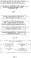
- FIG. 1 is a flow chart showing a method for transmitting information according to an exemplary embodiment, the method may include the following steps:
- step 11 frequency information of a second carrier for bearing subsequent scheduling data information is determined.
- the base station may determine the frequency information of the second carrier for bearing subsequent scheduling data information at any of the following occasions:
- the base station needs to determine the carrier for bearing subsequent scheduling data information, that is, the frequency information of the second carrier.
- step 12 a current radio frequency support capability of a user equipment is determined.
- the implementation of the foregoing step 12 may include two cases: In a first case, the radio support capability of the target UE is preset in the base station;
- the base station may determine the current radio frequency support capability of the target UE according to a frequency range of the first carrier.
- UE1 can support two operating frequency bands.
- a correspondence between a device identifier of the UE1 and the supported operating frequency band is preset in the base station, which is illustratively shown in Table 1: Table 1 device identifier operating frequency band UE1 4.910GHz ⁇ 4.920GHz 5.910GHz ⁇ 5.920GHz
- the base station can learn that: the current radio frequency support capability of the UE1 is 4.910 GHz to 4.920 GHz.
- the radio frequency support capability information of the target UE is not stored in the base station in advance; the base station may obtain the current radio support capability of the target UE by using at least one of the following methods:
- the base station receives the current radio frequency support capability reported by the target UE;
- the UE can support at least two operating frequency bands, and each operating frequency band corresponds to one type of radio frequency support capability information.
- the radio frequency support capability information may be expressed as at least one of the following: a bandwidth, a frequency range of the operating frequency band, at least two sensitive frequency points outside the operating frequency band, and a radio frequency tuning speed.
- the radio frequency tuning speed may be the radio frequency tuning speed of the target UE as a whole or the radio frequency tuning speed of the current radio frequency transceiver module.
- a user equipment may report the radio frequency support capability information of each operating frequency band to the base station covering the cell when accessing a cell network for the first time, or obtain the radio frequency support capability information of the current operating frequency band of the UE, when communicating with the base station through the first carrier, so that when the base station schedules different carriers to send information to the user equipment, it can determine whether it is necessary to issue scheduling information related to the subsequent scheduling to the user equipment according to the current radio frequency support capability of the UE.
- the base station may first obtain the device type information of the target UE, for example, the unified category information; the base station queries a device capability list stored in a preset database according to the device type information of the target UE, and determine the radio frequency support capability of the target UE.
- the device capability list records the correspondence between the device type and the radio frequency support capability.
- the current radio frequency support capability of the target UE is determined according to the frequency range of the first carrier.
- step 13 if frequency of the second carrier exceeds the current radio frequency support capability of the user equipment, scheduling information of the second carrier is sent to the user equipment through a first carrier;
- the scheduling information of the second carrier refers to the scheduling information related to the second carrier and transmitted through the first carrier.
- the scheduling information of the second carrier includes at least: additional scheduling information of the subsequent scheduling, and may further include: scheduling control information of the subsequent scheduling.
- the additional scheduling information of the subsequent scheduling includes: the frequency information of the second carrier, and the scheduling time of the second carrier, and may further include: a location of scheduling control information of the subsequent scheduling.
- the location of the scheduling control information of the subsequent scheduling refers to the location information of the scheduling control information of the subsequent scheduling in the second carrier resource.
- the base station may determine whether the frequency of the second carrier exceeds the current radio frequency support capability of the user equipment, according to the frequency information of the second carrier and the current operating frequency band of the UE.
- the embodiment of the present disclosure may determine the frequency of the second carrier exceeds the current radio frequency support capability of the user equipment by using the following four manners:
- the base station can determine the frequency span of the second carrier relative to the first carrier, for example, 1 GHz. After comparison, the frequency span is far beyond the bandwidth of the current operating frequency band of the UE, and it is determined that the frequency of the second carrier exceeds the current radio frequency support capability of the UE.
- the current radio frequency support capability of the user equipment obtained by the base station is a frequency range of the current operating frequency band of the UE, for example, 4.910 GHz to 4.920 GHz; and it is assumed that the frequency range of the second carrier determined by the base station is: 5.900 GHz to 5.920 GHz; after comparison of the specific frequency range, it can be known that the frequency of the second carrier exceeds the current radio frequency support capability of the UE.
- the current radio frequency support capability of the user equipment obtained by the base station is at least two sensitive frequency points except the current operating frequency band of the UE.
- the current operating frequency band of the UE is: 4.910 GHz to 4.920 GHz
- the UE can report two sensitive frequency points to the base station, for example, 4.900 GHz and 4.930 GHz; if the frequency span range between the second carrier and the first carrier includes any of the sensitive frequency points, it is determined that the frequency of the second carrier exceeds the current radio frequency support capability of the UE.
- the current operating frequency band of the UE is: 5.900 GHz to 5.920 GHz
- the frequency span range between the second carrier and the first carrier is: 4.920 GHz to 5.900 GHz
- the frequency span range includes a sensitive frequency point of the UE, 4.930 GHz. Therefore, it can be determined that the frequency of the second carrier exceeds the current radio frequency support capability of the UE.
- the current radio frequency support capability of the user equipment obtained by the base station is the radio frequency tuning speed of the UE, that is, the frequency tuning range per unit time of the UE.
- the ratio between the frequency span switching from the first carrier to the second carrier and the interval duration of the original switching is greater than the radio frequency tuning speed of the target UE, it may be determined that the frequency of the second carrier exceeds the current radio frequency support capability of the UE.
- the base station After the base station determines that the frequency of the second carrier exceeds the current radio frequency support capability of the UE, the base station is required to notify the UE the information about the working frequency range of the second carrier and the scheduling time of the second carrier through the first carrier, so that the user equipment switches to the operating frequency band which can receive the second carrier, and is ready to receive the data information of the subsequent scheduling.
- the relationship between the subsequent scheduling and the second carrier is: the information of the subsequent scheduling which is at least the data information, is sent to the target UE through the second carrier.
- the additional scheduling information of the subsequent scheduling is sent to the UE through the first carrier.
- the scheduling control information of the subsequent scheduling may be sent to the UE through the first carrier, or may be issued to the UE through the second carrier.
- the base station before performing the subsequent scheduling, the base station first sends the additional scheduling information of subsequent scheduling to the user equipment through the first frequency range.
- the additional scheduling information of the subsequent scheduling includes: a frequency range of the second carrier and a scheduling time of the second carrier.
- the scheduling time of the second carrier may be specifically an interval duration between the carrier through which the base station schedules the first frequency range (that is, the first carrier) and the carrier through which the base station schedules the second frequency range (that is, the second carrier), that is, the Gp in the subsequent schematic diagram; or the specific time at which the base station prepares to schedule the second carrier.
- the base station may issue the scheduling information of the second carrier to the user equipment through the first carrier by using the following manners:
- the additional scheduling information of the subsequent scheduling is sent to the user equipment
- the additional scheduling information of the subsequent scheduling further includes: a location of the scheduling control information of the subsequent scheduling in the second carrier resource, that is, a location of the scheduling control information of the subsequent scheduling.
- step 13 may include:
- step 1311 the additional scheduling information of the subsequent scheduling is determined
- the subsequent scheduling refers to a scheduling in which at least the data information is transmitted through the second carrier.
- the additional scheduling information of the subsequent scheduling includes: a frequency range of the second carrier, a scheduling time of the second carrier, and a location of scheduling control information of the subsequent scheduling;
- determining the scheduling time of the second carrier the following at least two determining manners may be included:
- a time value is estimated empirically, which is set as the switching interval duration Gp between the first carrier and the second carrier, that is, the scheduling time of the second carrier, thereby ensuring that the target UE can successfully complete the switching of the operating frequency band before the base station switches to the second carri er.
- the scheduling time of the second carrier is determined according to the radio frequency tuning speed of the target UE.
- the base station needs to re-determine the interval duration Gp switching from the first carrier to the second carrier.
- the base station may determine the scheduling time of the second carrier according to the radio frequency tuning speed of the UE, including the following steps:
- step A according to a current operating frequency band of the UE and the radio frequency tuning speed of the UE, a tuning duration required for the UE to be tuned from the current operating frequency band to a frequency band corresponding to the second carrier is determined.
- the radio frequency tuning speed when the radio frequency tuning speed is reported to the base station by the target UE, it may not be a specific natural value, but a code representation of the preset bit corresponding to the radio frequency tuning speed range where the radio frequency tuning speed is located, to reduce system signaling overhead and save transmission resources.
- the current radio frequency tuning speed of the UE is: 820 MHz/s.
- the correspondence between the tuning speed range and the speed code is preset in the base station and the UE, and it is assumed that the speed code is represented by 2 bits, which is illustratively shown in Table 2: Table 2 radio frequency tuning speed range (Unit : MHz/s) speed code 100 ⁇ 300 00 300 ⁇ 600 01 600 ⁇ 900 10 900 ⁇ 1200 11
- Table 2 radio frequency tuning speed range (Unit : MHz/s) speed code 100 ⁇ 300 00 300 ⁇ 600 01 600 ⁇ 900 10 900 ⁇ 1200 11
- the target UE can send the speed code 10 to the base station, so that the base station can determine the current radio frequency tuning speed of the target UE.
- the base station when calculating the tuning duration required by the target UE, can calculate the tuning duration according to the lowest radio frequency tuning speed of the speed range, thereby ensuring that the interval duration Gp of the second scheduling determined in the subsequent step B is sufficiently long, so that the target UE has sufficient switching time.
- step B the scheduling time of the second carrier is determined, according to an end time of the current scheduling and the tuning duration.
- the interval of the scheduling time of the second carrier (that is, the interval duration switching from the first carrier to the second carrier) is determined, according to the tuning duration of the UE.
- the interval of the scheduling time of the second carrier is greater than or equal to the tuning duration to ensure that the target UE already has had the radio frequency support capability for receiving the second carrier, when the base station schedules the second carrier to send the data information of the subsequent scheduling to the target UE.
- the scheduling control information of the subsequent scheduling may be set in the second carrier resource by using the following at least two manners:
- the scheduling control information of the subsequent scheduling is set in the second carrier by using the lag processing manner.
- the scheduling control information Dc2 of the subsequent scheduling is generally set at the header of the information transmission resource, for example, set in the header of the sub-frame of the subsequent scheduling (that is, in the symbol 0); in the embodiment of the present disclosure, the scheduling control information Dc2 of the subsequent scheduling may be set in the symbol 1 or the symbol 2 of the sub-frame of the subsequent scheduling by a lag manner.
- the base station may set the scheduling control information Dc2 of the subsequent scheduling to be in the second control information transmission unit (that is, in the symbol 1) by a lag manner, and the location of the scheduling control information of the subsequent scheduling is specifically the symbol 1.
- the scheduling control information of the subsequent scheduling is set in the second carrier by using a redundancy processing manner.
- the scheduling control information Dc2 of the subsequent scheduling is loaded in the symbol 0 and symbol 1 redundantly, the location of the scheduling control information of the subsequent scheduling is specifically the symbol 0 and the symbol 1.
- the two setting manner of Dc2 can avoid the user equipment from missing the reception of Dc2 due to the switching of the radio frequency transceiver module, thereby ensuring that the UE can receive the scheduling control information of the subsequent scheduling, further smoothly obtaining the data information of the subsequent scheduling, and avoiding the situation that the subsequent scheduling information cannot be received.
- step 1312 the additional scheduling information of the subsequent scheduling together with scheduling control information of a current scheduling is sent to the user equipment.
- the current scheduling refers to a scheduling in which the scheduling control information and the data information is both transmitted through the first carrier.
- the UE can successfully receive the control information issued by the base station.
- the base station may send the additional scheduling information Dc0 of the subsequent scheduling together with the scheduling control information Dclof the current scheduling to the user equipment when performing the current scheduling, so that the UE may obtain the frequency information and the scheduling time of the second carrier, and the location of the scheduling control information of the subsequent scheduling in advance, and prepare the obtaining of the information of the subsequent scheduling in advance to avoid missing the information of the subsequent scheduling.
- the additional scheduling information of the subsequent scheduling to the user equipment is sent to the user equipment through the first carrier.
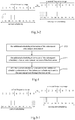
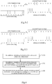
- the completion of the current scheduling is defined by the completion of the transmission of data information, as shown in FIGS. 3-1 , 3-2 , 5-1-5-3 , 7-1, 7-2 , the basic data information transmission unit Dd bears the data information.
- step 13 may include:
- step 1321 the additional scheduling information of the subsequent scheduling is determined, wherein, the additional scheduling information of the subsequent scheduling includes: a frequency range of the second carrier, a scheduling time of the second carrier, and a location of scheduling control information of the subsequent scheduling.
- the additional scheduling information of the subsequent scheduling includes: a frequency range of the second carrier, a scheduling time of the second carrier, and a location of scheduling control information of the subsequent scheduling.
- step 1322 the additional scheduling information of the subsequent scheduling is loaded into a preset resource of the first carrier.
- the additional scheduling information of the subsequent scheduling may be loaded into a preset resource of the first carrier.
- the following two cases may be included:
- the base station may load the additional scheduling information Dc0 of the subsequent scheduling into the preset transmission resource for the downlink control information, for example, into the symbol 9 of the sub-frame of the first scheduling, and the additional scheduling information Dc0 is issued to the user equipment through the first frequency range (that is, the first carrier).
- the scheduling control information Dc2 of the subsequent scheduling is set in the second carrier by using the lag processing manner.
- the setting manner of the scheduling control information Dc2 of the subsequent scheduling belongs to the case of redundancy setting.
- the additional scheduling information Dc0 of the subsequent scheduling may be loaded into any one of the downlink data transmission unit of the current scheduling, that is, any Dd shown in FIG. 5-3 .
- the additional scheduling information Dc0 of the subsequent scheduling may be loaded into the last downlink data transmission unit of the first carrier, that is, the symbol 9, and the data information of the current scheduling is bear in a part of the resources in the symbol 9, and the remaining resources are used for bearing the additional scheduling information Dc0 of the subsequent scheduling.
- the base station may adopt a physical layer signaling, such as PDCCH (Physical Downlink Control Channel) signaling, and an upper layer signaling, such as RRC (Radio Resource Control) signaling, or the like, and the base station sends the additional scheduling information of the subsequent scheduling to the UE through the preset resource of the first carrier.
- a physical layer signaling such as PDCCH (Physical Downlink Control Channel) signaling
- an upper layer signaling such as RRC (Radio Resource Control) signaling, or the like
- step 1323 after the current scheduling is completed, the additional scheduling information of the subsequent scheduling is sent to the user equipment through the first carrier.
- the base station may separately issue the additional scheduling information Dc0 of the subsequent scheduling to the user equipment through the first carrier.
- the location of the scheduling control information Dc2 of the subsequent scheduling in the second carrier resource is not limited, and may be set in a lag manner as shown in FIG. 5-1 , or may be set in a redundancy manner as shown in the FIGs 5-2 and 5-3 .
- the additional scheduling information and the scheduling control information of the subsequent scheduling is sent through the first carrier.
- step 13 may include:
- step 1331 the additional scheduling information of the subsequent scheduling is determined.
- the additional scheduling information of the subsequent scheduling includes: a frequency range of the second carrier, a scheduling time of the second carrier, and may further include: a location of scheduling control information of the subsequent scheduling in the first carrier resource.
- step 1332 the additional scheduling information of the subsequent scheduling and the scheduling control information of the subsequent scheduling are loaded into the preset resources of the first carrier;
- the following at least two cases may be included:
- the additional scheduling information and the scheduling control information of the subsequent scheduling are respectively loaded in different downlink control transmission resources of the first carrier.
- the downlink control transmission resource is used for bearing downlink control information sent to the target UE.
- the downlink control information may include: the scheduling control information of the current scheduling, the additional scheduling information of the subsequent scheduling and the scheduling control information of the subsequent scheduling.
- FIG. 7-1 is a schematic diagram showing another application scenario for transmitting information according to an exemplary embodiment
- the additional scheduling information Dc0 of the subsequent scheduling together with the scheduling control information Dc1 of the current scheduling is loaded in the downlink control resource of the first carrier, as in the symbol 0; and the scheduling control information Dc2 of the subsequent scheduling is loaded in the downlink control resource of the first carrier, as in the symbol 9.
- the scheduling control information Dc2 of the subsequent scheduling may include the time interval Gp between the transmission of the control information of the subsequent scheduling and the data transmission of the subsequent scheduling, i.e., the time interval duration between the scheduling of the first carrier and the scheduling of the second carrier.
- the additional scheduling information and the scheduling control information of the subsequent scheduling are loaded into the same downlink control transmission resource in the first carrier.
- the additional scheduling information Dc0 of the subsequent scheduling may be loaded into the downlink control transmission resource of the first carrier together with the scheduling control information Dc2 of the subsequent scheduling; the downlink control information transmission resource is located at the end of the first carrier resource, such as in the symbol 9.
- step 1333 the additional scheduling information and the scheduling control information of the subsequent scheduling are sent to the user equipment through the first carrier.
- the base station when the current scheduling is performed, the base station carries the transmission of the additional scheduling information Dc0 of the subsequent scheduling; and after the current scheduling is completed, the scheduling control information Dc2 of the subsequent scheduling may be sent to the user equipment through a separate downlink control transmission resource in the first carrier.
- the additional scheduling information Dc0 of the subsequent scheduling is sent to the user equipment through the first carrier together with the scheduling control information Dc2.
- step 14 the information is continued to transmit to the user equipment through the second carrier according to the scheduling information of the second carrier.
- the base station after the base station completes the current scheduling and issues the additional scheduling information of the subsequent scheduling by using the first carrier (that is, the first frequency range), the base station sends the scheduling control information and the data information of the subsequent scheduling to the UE by using the second carrier (the second frequency range), according to the scheduling time of the second carrier, for example, the preset duration of interval Gp.
- the base station after the base station completes the current scheduling and issues the additional scheduling information and the scheduling control information of the subsequent scheduling by using the first carrier(that is, the first frequency range), the base station sends the data information of the subsequent scheduling to the UE by using the second carrier (the second frequency range), according to the scheduling time of the second carrier, for example, the preset duration of interval Gp.
- the present disclosure also provides a method for transmitting information, which is applied to a user equipment.
- a method for transmitting information which is applied to a user equipment.
- FIG. 8 which is a flow chart showing another method for transmitting information according to an exemplary embodiment, the method may include:
- step 21 the scheduling information of the second carrier is received through a first operating frequency band, wherein the scheduling information of the second carrier includes at least: additional scheduling information of subsequent scheduling;
- the additional scheduling information of the subsequent scheduling includes at least: a frequency range of the second carrier and a scheduling time of the second carrier.
- the additional scheduling information of the subsequent scheduling may further include: a setting location of the scheduling control information of the subsequent scheduling in the second carrier resource.
- the foregoing step 21 may include the following three implementation manners:
- the additional scheduling information of the subsequent scheduling is obtained, as shown in FIGS. 3-1 , 3-2 , and 7-1 ;
- the additional scheduling information of the subsequent scheduling is separately obtained through the first operating frequency band
- the UE may separately obtain the additional scheduling information of the subsequent scheduling by using the downlink control transmission resource of the first carrier, as shown in FIGS. 5-1 , 5-2 .
- the UE obtains the additional scheduling information of the subsequent scheduling from any downlink data transmission unit, for example, from the last downlink data transmission unit of the current scheduling, as shown in FIG. 5-3 .
- the additional scheduling information of the subsequent scheduling and the scheduling control information of the subsequent scheduling is received through the first operating frequency band, as shown in FIG. 7-2 .
- step 22 the first operating frequency band is switched to the second operating frequency band according to the additional scheduling information of the subsequent scheduling
- the smart phone A is provided with at least two radio frequency transceiver modules. It is assumed that the first radio frequency transceiver module belongs to a low frequency module supporting the LTE system of the 4G network, and the corresponding first operating frequency band is 4900MHz ⁇ 4920MHz; the second radio frequency transceiver module belongs to a high-frequency module supporting 5G system (that is, a NR system), and it is assumed that the operating frequency band is: 5900MHz ⁇ 5920MHz.
- the frequency range of the first carrier used by the base station to transmit the current scheduling information is: 4910 MHz to 4920 MHz
- the smartphone A enables the first radio frequency transceiver module to receive the information issued by the first carrier.
- the base station prepares to use the second carrier having a frequency range of 5910 MHz to 5920 MHz at the next time to transmit the data of the subsequent scheduling to the smartphone A.
- the base station sends the additional scheduling information, such as the frequency information and the scheduling time of the second carrier, and the like to the smart phone A through the first carrier to enable smartphone A to switch the operating frequency band.
- the frequency information of the second carrier included in the additional scheduling information Dc0 that is obtained by the smartphone A may be specifically: 5910 MHz to 5920 MHz, or the frequency span of the second carrier relative to the first carrier included in the additional scheduling information Dc0 that is obtained by the smartphone A may be 1 GHz. Since the frequency span exceeds the radio frequency support capability of the first radio frequency transceiver module, the smart phone A switches the current working radio frequency module from the first radio frequency transceiver module to the second radio frequency transceiver module, that is, from the first operating frequency band to the second operating frequency band.
- step 23 the subsequent scheduling information is received through the second operating frequency band.
- the frequency range of the second operating frequency band of the UE and the frequency range of the second carrier are intersected.
- the implementation of the step 23 may include the following two cases:
- control information and the data information of the subsequent scheduling are obtained through the second operating frequency band.
- step 23 may include:
- step 231 the scheduling control information of the subsequent scheduling is obtained through the second operating frequency band
- the scheduling control information Dc2 of the subsequent scheduling may be obtained by using the following at least two manners:
- the scheduling control information Dc2 of the subsequent scheduling is obtained at the header of the sub-frame of the subsequent scheduling.
- the scheduling control information of the subsequent scheduling is set in the header of the second carrier resource. It is assumed that the second carrier resource performs the information transmission in units of sub-frame. Each sub-frame consists of 10 symbols with sequence numbers from 0 to 9. According to the preset protocol, the scheduling control information is set in the symbol of the header of the sub-frame, such as in the symbol 0. Then, when the second carrier is detected, the smartphone A obtains the scheduling control information Dc2 of the subsequent scheduling from the header of the carrier resource, that is, the symbol 0.
- the scheduling control information of the subsequent scheduling is obtained from the second carrier resource according to the location information of the Dc2 included in the additional scheduling information Dc0 of the subsequent scheduling.
- the base station in order to ensure that the smart phone A can successfully obtain the scheduling control information Dc2 of the subsequent scheduling through the second carrier, the base station can also load Dc2 into the preset resource of the second carrier in a lag setting or redundancy setting manner.
- the base station may inform the user equipment of the location of the Dc2 in the second carrier through the additional scheduling information Dc0 of the subsequent scheduling.
- the smart phone A can obtain the scheduling control information of the subsequent scheduling through the second carrier according to the location information of Dc2, as shown in FIGS.3-1 , 3-2 , 5-1 , 5-2, and 5-3 .
- step 232 the data information of the subsequent scheduling is obtained according to the scheduling control information of the subsequent scheduling.
- the scheduling control information of the second carrier issued by the base station to the target UE is used to notify the target UE of what time-frequency resource block, what modulation coding scheme, and what MIMO operation mode to transmit downlink data information to the target UE.
- the UE may obtain the data information from the downlink resources of the base station.
- the scheduling control information Dc2 of the subsequent scheduling includes: the time frequency resource for bearing the data information of the subsequent scheduling, coding and decoding modes of the data information of the subsequent scheduling and the like. Therefore, the smart phone A can obtain the data information of the subsequent scheduling according to Dc2.
- the data information of the subsequent scheduling is obtained through the second operating frequency band.
- the second operating frequency band is only used to obtain the data information of the subsequent scheduling.
- FIG. 10 which is a flow chart showing another method for transmitting information according to an exemplary embodiment, on the basis of the embodiment shown in FIG 8 , before the step 21, the method may further include:
- step 20 the information of the radio frequency support capability information is reported to the base station, wherein the information of the radio frequency support capability includes: a bandwidth or frequency range of the current operating frequency band of the user equipment, at least two sensitive frequency points outside the current operating frequency band of the user equipment, or the radio frequency tuning speed of the user equipment.
- the smart phone A can actively report the radio frequency support capability information of each operating frequency band, in the case that the smart phone A first accesses to the base station of the cell in the first time.
- the operating frequency bands of the respective radio frequency transceiver modules are different.
- the radio frequency support capability information of each radio frequency transceiver module may be the bandwidth of the operating frequency band, such as 10 MHz; or the specific frequency range of the operating frequency band, for example, 4910 MHz to 4920 MHz; or at least two sensitive frequency points outside the operating frequency band, such as 4920MHz, 4930MHz.
- the UE may also report the radio frequency support capability information of the current operating frequency band to the base station when communicating with the base station through the first carrier.
- the method provided by the present disclosure may first notify the user equipment in advance by using the first carrier, when it is determined that the frequency span of the second carrier exceeds the current radio frequency support capability of the UE, so that the user equipment can adjust the operating frequency band in time after receiving the first scheduling information, thereby ensuring that the frequency band conversion is completed before the second carrier arrives, and ensuring successful reception of the subsequent scheduling data, reducing unnecessary retransmission, saving system resources, improving information transmission efficiency and reliability of information transmission.
- the present disclosure also provides the embodiments of the application function implementation device and a corresponding terminal.
- FIG. 11 which is a block diagram showing a device for transmitting information according to an exemplary embodiment of the present disclosure, provided in a base station which establishes a connection with a user equipment via a first carrier, and the device may include:
- the carrier information sending module 33 may include a first additional information determining sub-module 3311, configured to determine additional scheduling information of the subsequent scheduling, wherein, the additional scheduling information of the subsequent scheduling includes: a frequency range of the second carrier, a scheduling time of the second carrier, and a location of scheduling control information of the subsequent scheduling; a first information sending sub-module 3312, configured to send the additional scheduling information of the subsequent scheduling together with scheduling control information of a current scheduling to the user equipment; wherein, the current scheduling refers to a scheduling in which data information transmission is bear by the first carrier; and the subsequent scheduling refers to a scheduling in which the data information transmission is bear by the second carrier.
- the carrier information sending module 33 may include:
- the carrier information sending module 33 may include:
- any of the above additional information determining sub-modules may determine the scheduling time of the second carrier in the additional scheduling information of the subsequent scheduling according to the radio frequency tuning speed of the user equipment.
- the third additional information determining sub-module 3331 taken as an example, referring to FIG. 15 , which is a block diagram showing another device for transmitting information according to an exemplary embodiment, on the basis of the embodiment of the device shown in FIG. 14 , the third additional information determining sub-module 3331 may include:
- first additional information determining sub-module 3311 and the second additional information determining sub-module 3321 may include: the tuning duration determining unit 3301 and the scheduling time determining unit 3302.
- the above data transmitting module 34 in FIG. 11 may include the following: a first transmitting sub-module 341, configured to send the scheduling control information and data information of the subsequent scheduling to the user equipment through the second carrier according to the scheduling time of the second carrier, after the additional scheduling information of the subsequent scheduling and the current scheduling is completed by using the first carrier.
- the above data transmitting module 34 in FIG. 11 may include: a second transmitting sub-module 342, configured to send the data information of the subsequent scheduling to the user equipment through the second carrier according to the scheduling time of the second carrier, after the current scheduling, the additional scheduling information for transmitting the subsequent scheduling and the scheduling control information of the subsequent scheduling is completed by using the first carrier.
- the capability determining module 32 may include:
- the present disclosure also provides a device for transmitting information, provided in the user equipment.
- the device may include:
- the first information receiving module 41 may include any of the following additional information receiving sub-module:
- the second information receiving module 42 may include:
- the device may further include:
- the device embodiment since it basically corresponds to the method embodiment, it can be referred to the description of the method embodiment.
- the device embodiments described above are merely illustrative, wherein the units described as separate components may or may not be physically separated, and the components displayed as units may or may not be physical units, that is, may be located in one place, or they can be distributed to the multiple network elements. Some or all of the modules may be selected according to actual needs to achieve the objectives of the present disclosure. Those skilled in the art can understand and implement the method without any inventive work.
- a device for transmitting information including: a processor; and a memory for storing instructions executable for the processor; wherein the processor is configured to: determine frequency information of a second carrier for bearing subsequent scheduling data information; determine a current radio frequency support capability of a user equipment; if frequency of the second carrier exceeds the current radio frequency support capability of the user equipment, send scheduling information of the second carrier to the user equipment through a first carrier; and continue to transmit information to the user equipment through the second carrier according to the scheduling information of the second carrier.
- a device for transmitting information including: a processor; and a memory for storing instructions executable for the processor; wherein the processor is configured to: receive scheduling information of a second carrier through a first operating frequency band, wherein the scheduling information of the second carrier includes at least: additional scheduling information of subsequent scheduling; switch the first operating frequency band to a second operating frequency band according to the additional scheduling information of the subsequent scheduling; and receive the subsequent scheduling through the second operating frequency band.
- the device 2300 can be provided as a base station.
- the device 2300 includes a processing component 2322, a wireless transmitting/receiving component 2324, an antenna component 2326, and a signal processing portions specific to the wireless interface.
- the processing component 2322 may further include one or more processors.
- One of the processing components 2322 can be configured to:
- non-transitory computer-readable storage medium storing computer instructions thereon.
- the computer instructions are executed by the processing components 2322 of the device 2300 to perform any of the above method for transmitting information.
- the non-transitory computer readable storage medium may be a ROM, a random access memory (RAM), a CD-ROM, a magnetic tape, a floppy disc, and an optical data storage device.
- FIG. 24 is a schematic structural diagram showing a device 2400 for transmitting information according to an exemplary embodiment.
- the device 2400 may be a user equipment in a 5G network, and may specifically be a mobile phone, a computer, a digital broadcast terminal, a messaging device, a game console, a tablet device, a medical device, a fitness device, a personal digital assistant, a wearable device, such as a smart watch, smart glasses, a smart bracelet, smart running shoes, etc., can belong to eMBB (Enhanced Mobile Broad Band), mMTC (Massive Machine Type Communication), URLLC (Ultra Reliable Low Latency Communication) and other types of equipment in 5G network.
- eMBB Enhanced Mobile Broad Band
- mMTC Massive Machine Type Communication
- URLLC Ultra Reliable Low Latency Communication
- the device 2400 may include one or more of the following components: a processing component 2402, a memory 2404, a power component 2406, a multimedia component 2408, an audio component 2410, an input/output (I/O) interface 2412, a sensor component 2414, and a communication component 2416.
- a processing component 2402 may include one or more of the following components: a processing component 2402, a memory 2404, a power component 2406, a multimedia component 2408, an audio component 2410, an input/output (I/O) interface 2412, a sensor component 2414, and a communication component 2416.
- the processing component 2402 typically controls the overall operations of the device 2400, such as the operations associated with display, telephone calls, data communications, camera operations, and recording operations.
- the processing component 2402 can include one or more processors 2420 to execute instructions to perform all or part of the steps in the above described methods.
- the processing component 2402 can include one or more modules to facilitate the interaction between the processing component 2402 and other components.
- the processing component 2402 can include a multimedia module to facilitate the interaction between the multimedia component 2408 and the processing component 2402.
- the memory 2404 is configured to store various types of data to support the operation of the device 2400. Examples of such data include instructions for any application or method operated on device 2400, such as the contact data, the phone book data, messages, pictures, videos, and the like.
- the memory 2404 can be implemented by any type of volatile or non-volatile storage device, or a combination thereof, such as a static random access memory (SRAM), an electrically erasable programmable read-only memory (EEPROM), an erasable programmable read-only memory (EPROM), a programmable read-only memory (PROM), a read-only memory (ROM), a magnetic memory, a flash memory, a magnetic or optical disk.
- SRAM static random access memory
- EEPROM electrically erasable programmable read-only memory
- EPROM erasable programmable read-only memory
- PROM programmable read-only memory
- ROM read-only memory
- magnetic memory a magnetic memory
- flash memory a flash memory
- the power component 2406 provides power to various components of the device 2400.
- the power component 2406 can include a power management system, one or more power sources, and other components associated with with the generation, management, and distribution of power in the device 2400.
- the multimedia component 2408 includes a screen providing an output interface between the device 2400 and the user t.
- the screen can include a liquid crystal display (LCD) and a touch panel (TP). If the screen includes the touch panel, the screen can be implemented as a touch screen to receive input signals from the user.
- the touch panel includes one or more touch sensors to sense touches, swipes, and gestures on the touch panel. The touch sensors may not only sense a boundary of a touch or swipe action, but also sense a period of time and a pressure associated with the touch or swipe action.
- the multimedia component 2408 includes a front camera and/or a rear camera.
- the front camera and/or the rear camera can receive external multimedia datum.
- the front camera and the rear camera may be a fixed optical lens system or have focus and optical zoom capability.
- the audio component 2410 is configured to output and/or input an audio signal.
- the audio component 2410 includes a microphone (MIC) configured to receive an external audio signal when the device 2400 is in an operation mode, such as a call mode, a recording mode, and a voice recognition mode.
- the received audio signal may be further stored in the memory 2404 or sent via the communication component 2416.
- the audio component 2410 also includes a speaker for outputting the audio signal.
- the I/O interface 2412 provides an interface between the processing component 2402 and peripheral interface modules, such as a keyboard, a click wheel, buttons, and the like. These buttons may include, but are not limited to, a home button, a volume button, a starting button, and a locking button.
- the sensor component 2414 includes one or more sensors for providing status assessments of various aspects of the device 2400.
- the sensor component 2414 can detect an open/closed status of the device 2400, relative locating of components, such as the display and the keypad of the device 2400.
- the sensor component 2414 can also detect a change in location of one component of the device 2400 or the device 2400, the presence or absence of user contact with the device 2400, an orientation, or an acceleration/deceleration of the device 2400, and a change in temperature of the device 2400.
- the sensor component 2414 can include a proximity sensor configured to detect the presence of nearby objects without any physical contact.
- the sensor component 2414 can also include a light sensor, such as a CMOS or CCD image sensor, configured to use in imaging applications.
- the sensor component 2414 can also include an accelerometer sensor, a gyroscope sensor, a magnetic sensor, a pressure sensor, or a temperature sensor.
- the communication component 2416 is configured to facilitate wired or wireless communication between the device 2400 and other devices.
- the device 2400 can access a wireless network based on a communication standard, such as WiFi, 2G or 3G, or a combination thereof.
- the communication component 2416 receives broadcast signals or broadcast associated information from an external broadcast management system via a broadcast channel.
- the communication component 2416 also includes a near field communication (NFC) module to facilitate short-range communications.
- the NFC module can be implemented based on a radio frequency identification (RFID) technology, an infrared data association (IrDA) technology, an ultra-wideband (UWB) technology, a Bluetooth (BT) technology, and other technologies.
- RFID radio frequency identification
- IrDA infrared data association
- UWB ultra-wideband
- BT Bluetooth
- the device 2400 may be implemented with one or more application specific integrated circuits (ASICs), digital signal processors (DSPs), digital signal processing devices (DSPDs), programmable logic devices (PLDs), field programmable Gate array (FPGA), controller, microcontroller, microprocessor or other electronic components.
- ASICs application specific integrated circuits
- DSPs digital signal processors
- DSPDs digital signal processing devices
- PLDs programmable logic devices
- FPGA field programmable Gate array
- controller microcontroller, microprocessor or other electronic components.
- a non-transitory computer-readable storage medium storing computer instructions thereon, such as a memory 2404 including instructions executable by the processor 2420 of the device 2400 to perform the above method for transmitting information.
- the non-transitory computer readable storage medium may be a ROM, a random access memory (RAM), a CD-ROM, a magnetic tape, a floppy disc, and an optical data storage device.
Landscapes
- Engineering & Computer Science (AREA)
- Signal Processing (AREA)
- Computer Networks & Wireless Communication (AREA)
- Databases & Information Systems (AREA)
- Mobile Radio Communication Systems (AREA)
Applications Claiming Priority (1)
| Application Number | Priority Date | Filing Date | Title |
|---|---|---|---|
| PCT/CN2017/088691 WO2018227569A1 (fr) | 2017-06-16 | 2017-06-16 | Procédé et dispositif de transmission d'informations |
Publications (2)
| Publication Number | Publication Date |
|---|---|
| EP3641439A1 true EP3641439A1 (fr) | 2020-04-22 |
| EP3641439A4 EP3641439A4 (fr) | 2021-01-06 |
Family
ID=64660796
Family Applications (1)
| Application Number | Title | Priority Date | Filing Date |
|---|---|---|---|
| EP17914032.2A Pending EP3641439A4 (fr) | 2017-06-16 | 2017-06-16 | Procédé et dispositif de transmission d'informations |
Country Status (4)
| Country | Link |
|---|---|
| US (1) | US11405920B2 (fr) |
| EP (1) | EP3641439A4 (fr) |
| CN (1) | CN109429558B (fr) |
| WO (1) | WO2018227569A1 (fr) |
Cited By (1)
| Publication number | Priority date | Publication date | Assignee | Title |
|---|---|---|---|---|
| EP4412373A4 (fr) * | 2021-09-30 | 2024-12-25 | Vivo Mobile Communication Co., Ltd. | Procédé de rapport de capacité d'ue, procédé de programmation commun, procédé de programmation et dispositif |
Families Citing this family (4)
| Publication number | Priority date | Publication date | Assignee | Title |
|---|---|---|---|---|
| US11019544B2 (en) | 2017-02-02 | 2021-05-25 | Samsung Electronics Co., Ltd. | Method and apparatus for transmitting and receiving data in mobile communication system |
| US20220030592A1 (en) * | 2018-11-30 | 2022-01-27 | Sony Group Corporation | Terminal device and method |
| CN114208243B (zh) * | 2019-08-16 | 2025-06-06 | 华为技术有限公司 | 一种通信方法及装置 |
| WO2021035595A1 (fr) * | 2019-08-29 | 2021-03-04 | Qualcomm Incorporated | Configuration d'intervalles de garde pour de multiples porteuses de liaison montante |
Family Cites Families (13)
| Publication number | Priority date | Publication date | Assignee | Title |
|---|---|---|---|---|
| US8554225B2 (en) * | 2009-03-12 | 2013-10-08 | Lg Electronics Inc. | Method for switching operating carrier at a user equipment in wireless communication system |
| CN102264139A (zh) * | 2010-05-24 | 2011-11-30 | 中国移动通信集团公司 | Lte-a载波聚合系统上行参考信号传输方法以及基站和终端 |
| EP2604072B1 (fr) * | 2010-08-13 | 2018-07-18 | Telefonaktiebolaget LM Ericsson (publ) | Fonctionnement double d'un équipement d'utilisateur dans un spectre avec licence et sans licence |
| US20130010620A1 (en) * | 2011-07-10 | 2013-01-10 | Esmael Dinan | Connection Reconfiguration in a Multicarrier OFDM Network |
| CN103906243B (zh) * | 2012-12-28 | 2018-09-07 | 中国移动通信集团公司 | 一种辅载波的配置和资源调度的方法及系统 |
| US9119178B2 (en) * | 2013-02-08 | 2015-08-25 | Telefonaktiebolaget L M Ericsson (Publ) | Efficient transmission parameter selection |
| CN109728890B (zh) * | 2013-06-27 | 2021-11-19 | 华为技术有限公司 | 载波切换方法、基站和用户设备 |
| JP2016534661A (ja) * | 2013-09-13 | 2016-11-04 | 富士通株式会社 | キャリア変換方法、装置及びシステム |
| JP2017501632A (ja) * | 2014-09-29 | 2017-01-12 | 日本電気株式会社 | 非ライセンス帯域におけるシグナリング送信のための方法及びデバイス |
| US10772021B2 (en) * | 2014-12-05 | 2020-09-08 | Qualcomm Incorporated | Low latency and/or enhanced component carrier discovery for services and handover |
| WO2016106671A1 (fr) * | 2014-12-31 | 2016-07-07 | 华为技术有限公司 | Procédé de mesure de bande de fréquences sans licence et dispositif associé |
| CN104955017B (zh) * | 2015-05-15 | 2018-07-24 | 宇龙计算机通信科技(深圳)有限公司 | 基于多载波的d2d资源配置方法、装置、基站和终端 |
| KR20180090177A (ko) | 2017-02-02 | 2018-08-10 | 삼성전자주식회사 | 이동통신시스템에서 사용자 정보 유무에 따른 셀 재선택 방안 |
-
2017
- 2017-06-16 EP EP17914032.2A patent/EP3641439A4/fr active Pending
- 2017-06-16 CN CN201780000542.0A patent/CN109429558B/zh active Active
- 2017-06-16 WO PCT/CN2017/088691 patent/WO2018227569A1/fr not_active Ceased
- 2017-06-16 US US16/609,206 patent/US11405920B2/en active Active
Cited By (1)
| Publication number | Priority date | Publication date | Assignee | Title |
|---|---|---|---|---|
| EP4412373A4 (fr) * | 2021-09-30 | 2024-12-25 | Vivo Mobile Communication Co., Ltd. | Procédé de rapport de capacité d'ue, procédé de programmation commun, procédé de programmation et dispositif |
Also Published As
| Publication number | Publication date |
|---|---|
| WO2018227569A1 (fr) | 2018-12-20 |
| EP3641439A4 (fr) | 2021-01-06 |
| US11405920B2 (en) | 2022-08-02 |
| CN109429558A (zh) | 2019-03-05 |
| US20200068553A1 (en) | 2020-02-27 |
| CN109429558B (zh) | 2022-01-25 |
Similar Documents
| Publication | Publication Date | Title |
|---|---|---|
| US11350394B2 (en) | Resource configuration method, apparatus, user equipment, and base station | |
| US11038657B2 (en) | Method and apparatus for transmitting and obtaining uplink HARQ feedback | |
| US10735932B2 (en) | Information sending method, apparatus and storage medium | |
| US11405920B2 (en) | Method and device for transmitting information | |
| US11050526B2 (en) | Method and apparatus for transmitting and obtaining uplink HARQ feedback | |
| US11490405B2 (en) | Method for transmitting information, base station and user equipment | |
| US20230254818A1 (en) | Resource allocation method and resource allocation apparatus | |
| US11910445B2 (en) | Random access method and device | |
| US20210297222A1 (en) | Method for transmitting harq feedback information, terminal, and base station | |
| US20210377970A1 (en) | Method, device and medium for transmitting information | |
| US11418290B2 (en) | Method and apparatus for transmitting data | |
| US20190320346A1 (en) | Method and device for transmitting downlink data | |
| US20240235784A1 (en) | Method and apparatus for transmitting or receiving system message, and communication device | |
| US12041590B2 (en) | Carrier configuration method and device | |
| US12082190B2 (en) | Information transmission method and apparatus, and base station and terminal | |
| US12556347B2 (en) | Frequency switching method | |
| US11871430B2 (en) | Downlink control channel receiving and transmitting method and device | |
| EP3735059B1 (fr) | Procédé et dispositif de détermination d'informations de direction de transmission |
Legal Events
| Date | Code | Title | Description |
|---|---|---|---|
| STAA | Information on the status of an ep patent application or granted ep patent |
Free format text: STATUS: THE INTERNATIONAL PUBLICATION HAS BEEN MADE |
|
| PUAI | Public reference made under article 153(3) epc to a published international application that has entered the european phase |
Free format text: ORIGINAL CODE: 0009012 |
|
| STAA | Information on the status of an ep patent application or granted ep patent |
Free format text: STATUS: REQUEST FOR EXAMINATION WAS MADE |
|
| 17P | Request for examination filed |
Effective date: 20200116 |
|
| AK | Designated contracting states |
Kind code of ref document: A1 Designated state(s): AL AT BE BG CH CY CZ DE DK EE ES FI FR GB GR HR HU IE IS IT LI LT LU LV MC MK MT NL NO PL PT RO RS SE SI SK SM TR |
|
| AX | Request for extension of the european patent |
Extension state: BA ME |
|
| DAV | Request for validation of the european patent (deleted) | ||
| DAX | Request for extension of the european patent (deleted) | ||
| REG | Reference to a national code |
Ref country code: DE Ref legal event code: R079 Free format text: PREVIOUS MAIN CLASS: H04W0072040000 Ipc: H04W0072120000 |
|
| A4 | Supplementary search report drawn up and despatched |
Effective date: 20201209 |
|
| RIC1 | Information provided on ipc code assigned before grant |
Ipc: H04W 72/04 20090101ALN20201203BHEP Ipc: H04W 72/12 20090101AFI20201203BHEP Ipc: H04L 5/00 20060101ALN20201203BHEP |
|
| STAA | Information on the status of an ep patent application or granted ep patent |
Free format text: STATUS: EXAMINATION IS IN PROGRESS |
|
| 17Q | First examination report despatched |
Effective date: 20221215 |