EP3641520B1 - Machine de montage de composants électroniques - Google Patents
Machine de montage de composants électroniques Download PDFInfo
- Publication number
- EP3641520B1 EP3641520B1 EP17913661.9A EP17913661A EP3641520B1 EP 3641520 B1 EP3641520 B1 EP 3641520B1 EP 17913661 A EP17913661 A EP 17913661A EP 3641520 B1 EP3641520 B1 EP 3641520B1
- Authority
- EP
- European Patent Office
- Prior art keywords
- component
- section
- main body
- locking
- carrier tape
- Prior art date
- Legal status (The legal status is an assumption and is not a legal conclusion. Google has not performed a legal analysis and makes no representation as to the accuracy of the status listed.)
- Active
Links
Images




Classifications
-
- H—ELECTRICITY
- H05—ELECTRIC TECHNIQUES NOT OTHERWISE PROVIDED FOR
- H05K—PRINTED CIRCUITS; CASINGS OR CONSTRUCTIONAL DETAILS OF ELECTRIC APPARATUS; MANUFACTURE OF ASSEMBLAGES OF ELECTRICAL COMPONENTS
- H05K13/00—Apparatus or processes specially adapted for manufacturing or adjusting assemblages of electric components
- H05K13/04—Mounting of components, e.g. of leadless components
- H05K13/0404—Pick-and-place heads or apparatus, e.g. with jaws
- H05K13/0413—Pick-and-place heads or apparatus, e.g. with jaws with orientation of the component while holding it; Drive mechanisms for gripping tools, e.g. lifting, lowering or turning of gripping tools
-
- H—ELECTRICITY
- H05—ELECTRIC TECHNIQUES NOT OTHERWISE PROVIDED FOR
- H05K—PRINTED CIRCUITS; CASINGS OR CONSTRUCTIONAL DETAILS OF ELECTRIC APPARATUS; MANUFACTURE OF ASSEMBLAGES OF ELECTRICAL COMPONENTS
- H05K13/00—Apparatus or processes specially adapted for manufacturing or adjusting assemblages of electric components
- H05K13/04—Mounting of components, e.g. of leadless components
- H05K13/0404—Pick-and-place heads or apparatus, e.g. with jaws
- H05K13/0408—Incorporating a pick-up tool
-
- H—ELECTRICITY
- H05—ELECTRIC TECHNIQUES NOT OTHERWISE PROVIDED FOR
- H05K—PRINTED CIRCUITS; CASINGS OR CONSTRUCTIONAL DETAILS OF ELECTRIC APPARATUS; MANUFACTURE OF ASSEMBLAGES OF ELECTRICAL COMPONENTS
- H05K13/00—Apparatus or processes specially adapted for manufacturing or adjusting assemblages of electric components
- H05K13/04—Mounting of components, e.g. of leadless components
- H05K13/0417—Feeding with belts or tapes
-
- H—ELECTRICITY
- H05—ELECTRIC TECHNIQUES NOT OTHERWISE PROVIDED FOR
- H05K—PRINTED CIRCUITS; CASINGS OR CONSTRUCTIONAL DETAILS OF ELECTRIC APPARATUS; MANUFACTURE OF ASSEMBLAGES OF ELECTRICAL COMPONENTS
- H05K13/00—Apparatus or processes specially adapted for manufacturing or adjusting assemblages of electric components
- H05K13/04—Mounting of components, e.g. of leadless components
- H05K13/0417—Feeding with belts or tapes
- H05K13/0419—Feeding with belts or tapes tape feeders
-
- H—ELECTRICITY
- H05—ELECTRIC TECHNIQUES NOT OTHERWISE PROVIDED FOR
- H05K—PRINTED CIRCUITS; CASINGS OR CONSTRUCTIONAL DETAILS OF ELECTRIC APPARATUS; MANUFACTURE OF ASSEMBLAGES OF ELECTRICAL COMPONENTS
- H05K13/00—Apparatus or processes specially adapted for manufacturing or adjusting assemblages of electric components
- H05K13/08—Monitoring manufacture of assemblages
- H05K13/081—Integration of optical monitoring devices in assembly lines; Processes using optical monitoring devices specially adapted for controlling devices or machines in assembly lines
- H05K13/0812—Integration of optical monitoring devices in assembly lines; Processes using optical monitoring devices specially adapted for controlling devices or machines in assembly lines the monitoring devices being integrated in the mounting machine, e.g. for monitoring components, leads, component placement
-
- H—ELECTRICITY
- H05—ELECTRIC TECHNIQUES NOT OTHERWISE PROVIDED FOR
- H05K—PRINTED CIRCUITS; CASINGS OR CONSTRUCTIONAL DETAILS OF ELECTRIC APPARATUS; MANUFACTURE OF ASSEMBLAGES OF ELECTRICAL COMPONENTS
- H05K13/00—Apparatus or processes specially adapted for manufacturing or adjusting assemblages of electric components
- H05K13/04—Mounting of components, e.g. of leadless components
- H05K13/0404—Pick-and-place heads or apparatus, e.g. with jaws
- H05K13/0408—Incorporating a pick-up tool
- H05K13/0409—Sucking devices
Definitions
- the present invention relates to an electronic component mounting machine.
- a radial lead component having a component main body and leads extending downward from the component main body are known.
- the radial lead component is such that the leads are held by a carrier tape and a tape feeder feeds the radial lead component to a supply position by performing a feeding operation on the carrier tape.
- the radial lead component supplied to the supply position is held by a component holding section, and the component holding section attaches the radial lead component, removed from the carrier tape, to the board.
- Patent Document 1 discloses a technique of holding a component main body of a radial lead component with a suction nozzle which is a component holding section.
- Patent Document 2 discloses a technique of holding leads of a radial lead component with a transfer claw which is a component holding section.
- WO 2017/090131 A1 discloses a device for determining the use of a specific tool according to characteristics of a component, such as a radial lead component.
- the length from the upper end of the carrier tape to the lower end face of the component main body varies from carrier tape to carrier tape.
- the variation in the length from the upper end of the carrier tape to the lower end face of the component main body causes an error when the component main body of the radial lead component is held by the component holding section.
- the present invention discloses an electronic component mounting machine according to claim 1.
- the position control section calculates the position of the component holding section when holding the component main body based on the length from the upper end to the lower end of the component main body and the actual measured value of the length from the lower end of the component main body to the center of the feed hole.
- the electronic component mounting machine can accurately set the position of the component holding section when a component main body is held by performing a simple setting of the position control section, and thereby minimize the occurrence of an error when a radial lead component is held.
- component mounting machine 1 mainly includes board conveyance device 10, component supply device 20, and component transfer device 30.
- Board conveyance device 10 is a device for conveying board K in the X-axis direction.
- Board conveyance device 10 is of a so-called double conveyor type in which two conveyance devices 11 are arranged in parallel.
- conveyance device 11 a pair of guide rails are arranged in parallel along the X-axis direction, a pair of conveyor belts (not shown) are rotatably provided on the guide rails, and the conveyor belts convey board K by board K being placed thereon and the conveyor belts rotating.
- Board conveyance device 10 positions board K conveyed to the predetermined position, and when the mounting process of the component to board K is completed, board K is carried out to the outside of component mounting machine 1.
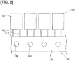
- Component supply device 20 is of a cassette type in which multiple tape feeders 21 are arranged in parallel on a base frame, and each tape feeder 21 is detachably mounted to base frame 2. Tape feeder 21 feeds radial lead component 110 (see Fig. 2 ) held on carrier tape 100 to a supply position and removes radial lead component 110 from carrier tape 100 at the supply position. Details of tape feeder 21 will be described later.
- Carrier tape 100 and radial lead component 110 will now be described with reference to Fig. 2 .
- carrier tape 100 is formed by attaching two long tape members 101, and radial lead component 110 is held between the two attached tape members 101.
- Carrier tape 100 is provided with multiple feed holes 102, the feed holes 102 penetrating carrier tape 100 at regular intervals in the longitudinal direction.
- Radial lead component 110 includes component main body 111 and two leads 112 extending downward from the lower face of component main body 111. Multiple radial lead components 110 held by carrier tape 100 are disposed at equal intervals so as to straddle feed holes 102 between the two leads 112 of each radial lead component 110.
- Component transfer device 30 collects radial lead component 110, supplied from component supply device 20 to the supply position, and mounts radial lead component 110 to a predetermined mounting position on positioned board K.
- Component transfer device 30 mainly includes head driving device 31, moving table 32, mounting head 33, component holding section 34, and position control section 35.
- Head driving device 31 is configured to move moving table 32 in the X-axis direction and the Y-axis direction by a linear movement mechanism
- mounting head 33 is configured to be detachable from moving table 32.
- Mounting head 33 is supported so as to be rotatable about an axis parallel to the Z-axis and is supported so as to move up and down in the Z-axis direction.
- Component holding section 34 is a suction nozzle capable of holding radial lead component 110 by suction.
- Component holding section 34 is detachably mounted on mounting head 33 and is supported by mounting head 33 so as to be rotatable about an axis parallel to the Z-axis and capable of moving up and down in the Z-axis direction.
- position control section 35 sets a target position for component holding section 34 upon holding radial lead component 110 and controls various motors so that component holding section 34 moves to the target position.
- Position control section 35 mainly includes information input section 36, target position calculation section 37, and mounting control section 38.
- Information input section 36 receives information outputted from various sensors provided in component mounting device 1 and results of various recognition processes.
- Information input section 36 includes first height input section 36a and second height input section 36b.
- Numerical values relating to the height of radial lead component 110 held on carrier tape 100 is inputted to first height input section 36a and second height input section 36b by the operator.
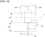
- first height H1 the length from the upper end to the lower end of component main body 111
- second height H2 the length from the lower end of component main body 111 to the center of feed hole 102
- target position calculation section 37 calculates the target position for component holding section 34 to be moved upon holding radial lead component 110.
- Mounting control section 38 controls the position and operation of component transfer device 30 based on the target position calculated by target position calculation section 37, other information inputted to information input section 36, a control program stored in advance, and the like.
- tape feeder 21 feeds carrier tape 100 in order to supply radial lead component 110 held by carrier tape 100 to the supply position.
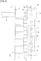
- tape feeder 21 mainly includes guide section 40, tape feeding section 50, and tape return prevention section 60.
- radial lead component 110 held by carrier tape 100 is not shown.
- Guide section 40 is provided on the distal end of tape feeder 21, that is, on the upper right side of Fig. 4 .
- Guide section 40 is formed by inner wall section 41 and outer wall section 42.
- Inner wall section 41 and outer wall section 42 are members having a substantially U-shaped form in plan view.
- Outer wall section 42 is provided on the outer side of inner wall section 41, and a gap capable of accommodating carrier tape 100 in an upright state exists between inner wall section 41 and outer wall section 42.
- Guide section 40 includes feed-side guide 43, curved guide 44, and return-side guide 45, and feed-side guide 43 and return-side guide 45 are coupled via curved guide 44.
- Feed-side guide 43 is a portion that is substantially straight in plan view and is a portion of guide section 40 that is upstream from the supply position.
- Cutting device 70 for cutting radial lead component 110 held by carrier tape 100 and removing radial lead component 110 from carrier tape 100 is provided at the supply position provided at the downstream end of feed-side guide 43.
- Curved guide 44 is a substantially U-shaped portion which is formed downstream from feed-side guide 43 in guide section 40 in plan view
- return-side guide 45 is a substantially straight portion which is formed downstream from feed-side guide 43 in guide section 40 in plan view.
- Curved guide 44 and return-side guide 45 guide carrier tape 100, from which radial lead component 110 has been removed at the supply position, to the outside of component supply device 20.
- feed-side slit 43a extending along the X-axis direction is formed at a portion where feed-side guide 43 is formed.
- return-side slit 45a extending along the X-axis direction is formed in a portion where return-side guide 45 is formed in inner wall section 41 and outer wall section 42.
- Tape feeding section 50 feeds carrier tape 100 accommodated in guide section 40.
- Tape feeding section 50 mainly includes first fixed section 51, first slider 52, second slider 53, two first locking sections 54, and second locking section 55.
- First fixed section 51 is a plate-like member provided in an upright state inside inner wall section 41.
- First slider 52 and second slider 53 are disposed on both sides with sandwiching first fixed section 51, and are supported by first fixed section 51 so as to be slidable in the X-axis direction.
- Pivot member 51a is pivotably supported in first fixed section 51, and first slider 52 is connected to one end of pivot member 51a, and second slider 53 is connected to the other end of pivot member 51a sandwiching the pivot rotation axis.
- first slider 52 and second slider 53 are configured to slide in opposite directions with respect to first fixed section 51.
- Two first locking sections 54 are provided such that a space is left between the two first locking sections 54 in the X-axis direction. Both first locking sections 54 are disposed between first slider 52 and inner wall section 41, each first locking sections 54 being swingable about an axis parallel to the Z-axis direction with respect to first slider 52, and slide integrally with first slider 52 in the X-axis direction with respect to first fixed section 51. Each first locking section 54 and first slider 52 are connected via spring 56, and spring 56 biases first locking section 54 in a direction away from first slider 52.
- First locking section 54 includes pivot support section 54a and claw section 54b.
- Pivot support section 54a is a portion on one end in the longitudinal direction of first locking section 54 and is attached to first slider 52 so as to be swingable about an axis parallel to the Z-axis direction.
- Claw section 54b is a portion formed on the other end in the longitudinal direction of first locking section 54 and protrudes toward the side opposite to first slider 52.
- Claw section 54b includes locking surface 54c and lock-release surface 54d.
- Locking surface 54c is a portion of the side face of claw section 54b that is oriented toward the supply position and is substantially orthogonal to the X-axis direction during normal operation shown in Fig. 5 .
- Lock-release surface 54d is a portion of the side surface of claw section 54b that is facing the side opposite to the supply position and slopes toward first slider 52 as it moves away from locking surface 54c in the X-axis direction.
- Each of claw sections 54b provided in two first locking sections 54 is inserted into feed-side slit 43a during normal operation, and first locking sections 54 slide in the X-axis direction in a state in which claw sections 54b are inserted into feed-side slit 43a from the inner wall section 41 side.
- Each claw section 54b is pulled out of feed-side slit 43a by pivoting first locking section 54 against the urging of spring 56.
- the distance between claw sections 54b provided in two first locking sections 54 corresponds to twice the distance between feed holes 102 in carrier tape 100.
- Second locking section 55 is disposed between second slider 53 and inner wall section 41. Second locking section 55 is supported by second slider 53 so as to be pivotable about an axis parallel to the Z-axis direction, and slides in the X-axis direction integrally with second slider 53 with respect to first fixed section 51. Second locking section 55 and second slider 53 are connected via spring 57, and spring 57 biases second locking section 55 in a direction away from second slider 53.
- Second locking section 55 includes pivot support section 55a and claw section 55b. Pivot support section 55a and claw section 55b have the same shape as swinging support section 54a and claw section 54b of first locking section 54, and claw section 55b protrudes toward the side opposite to second slider 53.
- Locking surface 55c faces the side opposite to the supply position and is substantially orthogonal to the X-axis direction during normal operation shown in Fig. 5 .
- lock-release surface 55d faces the supply position and slopes toward second slider 53 as it moves away from locking surface 55c in the X-axis direction.
- Claw section 55b provided to second locking section 55 is inserted into return-side slit 45a from inner wall section 41 side during normal operation, and second locking section 55 slides in the X-axis direction in a state in which claw section 55b is inserted into return-side slit 45a.
- Claw section 55b is pulled out of return-side slit 45a by pivoting second locking section 55 against the urging force of spring 56.
- Tape return prevention section 60 mainly includes second fixed section 61 and third locking section 62.
- Second fixed section 61 is provided in an upright state at a position facing the outer peripheral surface of the portion of outer wall section 42 where feed-side guide 43 is formed.
- Third locking section 62 is disposed between second fixed section 61 and outer wall section 42, and is supported so as to be pivotable about an axis parallel to the Z-axis direction. Third locking section 62 and second fixed section 61 are connected via spring 63, and spring 63 biases third locking section 62 in a direction away from second fixed section 61.
- Third locking section 62 includes pivot support section 62a and claw section 62b. Pivot support section 62a and claw section 62b have the same shape as pivot support sections 54a, 55a and claw sections 54b, 55b of first locking section 54 and second locking section 55, and claw section 62b protrudes to the side opposite to second fixed section 61.
- Locking surface 62c faces the supply position and is generally orthogonal to the X-axis direction during normal operation.
- unlocking surface 62d faces the side opposite to the supply position and slopes toward second fixed section 61 as it moves away from locking surface 62c in the X-axis direction.
- Claw section 62b provided in third locking section 62 is inserted into feed-side slit 43a from the outer wall section 42 side during normal operation. Further, claw section 62b is pulled out of return-side slit 45a by pivoting third locking section 62 against the urging force of spring 56.
- a cylinder device (not shown) for sliding first slider 52 in the X-axis direction is connected to first slider 52.
- tape feeding section 50 slides in a direction in which second slider 53 moves away from the supply position.
- tape feeding section 50 slides in the direction in which second slider 53 approaches the supply position.
- claw sections 54b of two first locking sections 54 inserted into feed-side slit 43a are inserted into feed holes 102 of carrier tape 100 guided by feed-side guide 43.
- claw section 55b of second locking section 55 inserted into return-side slit 45a is inserted into feed hole 102 of carrier tape 100 guided by return-side guide 45.
- Locking surfaces 54c of first locking sections 54 facing the supply position and locking surface 55c of second locking section 55 facing the side opposite to the supply position then engage with the inner peripheral surface of feed holes 102.
- radial lead component 110 is disposed at the supply position. Subsequently, component transfer device 30 holds by suction, with component holding section 34, the upper face of component main body 111 of radial lead component 110 supplied to the supply position. Thereafter, tape feeder 21 cuts lead 112 of radial lead component 110 suction and held by component holding section 34 with cutting device 70, and component transfer device 30 mounts held radial lead component 110 onto board K.
- tape feeder 21 drives the cylinder device (not shown) so that first slider 52 slides in the direction away from the supply position.
- first locking sections 54 start to slide in the direction away from the supply position
- second locking section 55 starts to slide in the direction toward the supply position.
- carrier tape 100 moves in a direction opposite to the feed direction of carrier tape 100 in conjunction with the sliding of first locking section 54 and second locking section 55.
- claw sections 54b of first locking sections 54 inserted into feed hole 102 are pushed to the inner peripheral surface of feed holes 102 by lock-release surfaces 54d coming into contact with the inner peripheral surface of feed holes 102.
- First locking sections 54 then pivot, and claw sections 54b come out of feed holes 102.
- claw section 55b of second engaging section 55 inserted into feed hole 102 is pushed to the inner peripheral surface of feed hole 102 by lock-release surface 55d coming into contact with the inner peripheral surface of feed hole 102.
- Second locking section 55 then pivots, and claw section 55b comes out of feed hole 102. Therefore, tape feeding section 50 can prevent carrier tape 100 from moving in the direction opposite to the feed direction when first locking sections 54 and second locking section 55 are returned to their original positions.
- first locking sections 54 and second locking section 55 are provided with claws sections 54b, 55b engageable with feed holes 102.
- Tape feeding section 50 then feeds carrier tape 100 by sliding first locking sections 54 and second locking section 55 while claw sections 54b of first locking sections 54 and claw section 55b of second locking section 55 are engaged with feed holes 102.
- third locking section 62 includes claw section 62b engageable with feed hole 102.
- Tape return prevention section 60 prevents carrier tape 100 from moving in the direction opposite to the feed direction by engaging claw section 62b of third locking section 62 with feed hole 102. In this way, tape feeder 21 can supply radial lead components 110 one by one to the supply position.
- the target position of component holding section 34 is calculated by position control section 35.
- component holding section 34 holds the upper face of component main body 111 by suction when holding radial lead component 110. Therefore, position control section 35 sets the upper face of component main body 111 of radial lead component 110, supplied to the supply position, as the target position, with radial lead component 110 being held by carrier tape 100.
- Target position calculation section 37 then calculates the target position based on first height H1 and second height H2 inputted by the operator.
- first height H1 and second height H2 are performed by the operator.
- second height H2 varies among carrier tapes 100, and the variation causes component holding errors, in which component main body 111 cannot be held by component holding section 34, or damage to radial lead component 110 from contact between component holding section 34 and component main body 111.
- the operator measures actual second height H2 and inputs the measured value to second height input section 36b.
- component holding section 34 sucks the upper face of component main body 111
- radial lead component 110 is held by carrier tape 100
- first locking sections 54 and second locking section 55 are inserted into feed holes 102 of carrier tape 100. Therefore, tape feeder 21 can arrange the center position of feed hole 102 in feed-side guide 43 at a constant height position while radial lead component 110 is supplied to the supply position.
- position control section 35 can accurately set the target position by setting the measured value of the length from the center of feed hole 102 to the lower end of component main body 111 as second height H2 and calculating the target position based on first height H1 and second height H2. In this manner, component mounting machine 1 can minimize errors that occur when a radial lead component is held by performing a simple setting of inputting first height H1 and second height H2.
- a pair of holding pawls for holding component main body 111 may be used as component holding section 234.
- position control section 35 sets the center portion in the height direction of component main body 111 as the target position, and calculates the target position based on first height H1 and second height H2 inputted to information input section 36. Therefore, even in this case, the component mounting machine can minimize errors that occur when the radial lead component is held by performing a simple setting of inputting first height H1 and second height H2.
- component transfer device 30 includes position control section 35 and the target position of component holding section 34 when holding radial lead component 110 is set by position control section 35
- an external terminal such as a personal computer
- an operator at the external terminal may edit data relating to the target position of component holding section 34 when radial lead component 110 is held and transmit the edited data from the external terminal to component mounting device 1.
Landscapes
- Engineering & Computer Science (AREA)
- Manufacturing & Machinery (AREA)
- Microelectronics & Electronic Packaging (AREA)
- Operations Research (AREA)
- Supply And Installment Of Electrical Components (AREA)
Claims (3)
- Machine de montage de composants électroniques (1), comprenant :un dispositif d'alimentation en composants (20) configuré pour fournir un composant à conducteurs radiaux (110) à une position d'alimentation en alimentant une bande de support (100) contenant de multiples composants à conducteurs radiaux (110), chaque composant à conducteurs radiaux (110) consistant en un corps principal de composant (111) et des conducteurs (112) s'étendant vers le bas à partir du corps principal de composant (111), dans lequel les conducteurs (112) sont maintenus par la bande de support (100) ; etun dispositif de transfert de composants (30) configuré pour collecter le composant à conducteurs radiaux (110) fourni à la position d'alimentation et monter le composant à conducteurs radiaux (110) à une position de montage prédéterminée ;dans lequel la bande de support (100) comprend plusieurs trous d'alimentation (102) à des intervalles dans le sens longitudinal ;dans lequel le dispositif d'alimentation en composants (20) comprend une section de verrouillage (54, 55) pouvant s'engager avec les trous d'alimentation (102), et comprend une section d'alimentation en bande (50) configurée pour alimenter la bande de support (100) en faisant glisser la section de verrouillage (54, 55) en engagement avec les trous d'alimentation (102) ; etdans lequel le dispositif de transfert de composants (30) comprend en outre :une section de maintien de composant (34) configurée pour maintenir le corps principal de composant (111) du composant à conducteurs radiaux (110) maintenu par la bande de support (100), etune section de commande de position (35) configurée pour commander la position de la section de maintien de composant (34) lorsqu'elle maintient le corps principal de composant (111), etdans lequel la section de commande de position (35) est configurée pour calculer la position de la section de maintien de composant (34), lorsqu'un corps principal de composant (111) est maintenu, sur la base de mesures réelles d'une longueur (H1) d'une extrémité supérieure à une extrémité inférieure du corps principal de composant (111) et d'une longueur (H2) de l'extrémité inférieure du corps principal de composant (111) au centre du trou d'alimentation (102), dans lequel la longueur (H1) de l'extrémité supérieure à l'extrémité inférieure du corps principal de composant (111) et la longueur (H2) de l'extrémité inférieure du corps principal de composant (111) au centre du trou d'alimentation (102) s'étendent dans le plan de la bande de support (100) et dans des sens parallèles, dans lequel les longueurs (H1, H2) sont entrées par un opérateur.
- Machine de montage de composants électroniques selon la revendication 1, dans laquelle la section de maintien de composants (34) est configurée pour maintenir le corps principal de composant (111) par aspiration.
- Machine de montage de composants électroniques selon la revendication 1, dans laquelle la section de maintien de composants (34) est configurée pour maintenir le corps principal de composant (111) en saisissant le corps principal de composant (111).
Applications Claiming Priority (1)
| Application Number | Priority Date | Filing Date | Title |
|---|---|---|---|
| PCT/JP2017/021944 WO2018229892A1 (fr) | 2017-06-14 | 2017-06-14 | Machine de montage de composants électroniques |
Publications (3)
| Publication Number | Publication Date |
|---|---|
| EP3641520A1 EP3641520A1 (fr) | 2020-04-22 |
| EP3641520A4 EP3641520A4 (fr) | 2020-05-27 |
| EP3641520B1 true EP3641520B1 (fr) | 2022-08-03 |
Family
ID=64660682
Family Applications (1)
| Application Number | Title | Priority Date | Filing Date |
|---|---|---|---|
| EP17913661.9A Active EP3641520B1 (fr) | 2017-06-14 | 2017-06-14 | Machine de montage de composants électroniques |
Country Status (5)
| Country | Link |
|---|---|
| US (1) | US11412647B2 (fr) |
| EP (1) | EP3641520B1 (fr) |
| JP (1) | JP6801099B2 (fr) |
| CN (1) | CN110741745B (fr) |
| WO (1) | WO2018229892A1 (fr) |
Families Citing this family (2)
| Publication number | Priority date | Publication date | Assignee | Title |
|---|---|---|---|---|
| JP7361532B2 (ja) * | 2019-08-20 | 2023-10-16 | 株式会社Fuji | テープフィーダ |
| EP4135502A4 (fr) * | 2020-04-06 | 2023-05-31 | Fuji Corporation | Dispositif d'alimentation à bande |
Family Cites Families (20)
| Publication number | Priority date | Publication date | Assignee | Title |
|---|---|---|---|---|
| US4245385A (en) * | 1979-07-09 | 1981-01-20 | Universal Instruments Corporation | Radial lead component insertion machine |
| JPS56118391A (en) * | 1980-02-25 | 1981-09-17 | Hitachi Ltd | Method and device for inserting electronic part |
| US5024129A (en) * | 1989-06-29 | 1991-06-18 | Gregory W. Holcomb | Radial lead component feeder having a narrow footprint |
| JP2926978B2 (ja) | 1990-11-22 | 1999-07-28 | 松下電器産業株式会社 | 電子部品切離装置 |
| JPH0543595U (ja) * | 1991-11-12 | 1993-06-11 | 日本ビクター株式会社 | ラジアルリード形テーピング電子部品 |
| JPH104294A (ja) * | 1996-06-18 | 1998-01-06 | Matsushita Electric Ind Co Ltd | 電子部品挿入装置 |
| JP3387881B2 (ja) * | 1999-03-17 | 2003-03-17 | ティーディーケイ株式会社 | 電子部品挿入ヘッドおよび電子部品挿入装置 |
| JP5434884B2 (ja) * | 2010-10-27 | 2014-03-05 | パナソニック株式会社 | 電子部品実装装置および電子部品実装方法 |
| JP5925523B2 (ja) * | 2012-02-08 | 2016-05-25 | Juki株式会社 | 電子部品実装装置、電子部品実装システム及び電子部品実装方法 |
| CN106879245A (zh) * | 2012-02-08 | 2017-06-20 | Juki株式会社 | 电子部件安装装置、电子部件安装系统以及电子部件安装方法 |
| JP5864294B2 (ja) * | 2012-02-08 | 2016-02-17 | Juki株式会社 | 電子部品実装方法及び電子部品実装装置 |
| JP6131006B2 (ja) * | 2012-07-25 | 2017-05-17 | Juki株式会社 | 情報管理システム |
| KR101365640B1 (ko) * | 2012-08-09 | 2014-02-21 | 주식회사 에이에스티젯텍 | 하우징 트레이의 이송장치 |
| JP5996983B2 (ja) * | 2012-09-19 | 2016-09-21 | ヤマハ発動機株式会社 | 電子部品装着装置 |
| JP6131045B2 (ja) * | 2012-12-28 | 2017-05-17 | Juki株式会社 | 電子部品実装装置及び電子部品実装方法 |
| JP6496148B2 (ja) * | 2014-04-29 | 2019-04-03 | Juki株式会社 | リード加工機構、部品供給装置、部品実装装置およびリード加工方法 |
| JP6457237B2 (ja) * | 2014-10-23 | 2019-01-23 | Juki株式会社 | リード切断方法および電子部品実装装置 |
| JP6590929B2 (ja) * | 2015-07-24 | 2019-10-16 | 株式会社Fuji | 部品フィーダ |
| JP6742334B2 (ja) * | 2015-11-25 | 2020-08-19 | 株式会社Fuji | ツール検索装置及びツール検索方法 |
| JP6154456B2 (ja) * | 2015-12-24 | 2017-06-28 | Juki株式会社 | 電子部品実装方法及び電子部品実装装置 |
-
2017
- 2017-06-14 US US16/615,456 patent/US11412647B2/en active Active
- 2017-06-14 CN CN201780092014.2A patent/CN110741745B/zh active Active
- 2017-06-14 JP JP2019524620A patent/JP6801099B2/ja active Active
- 2017-06-14 EP EP17913661.9A patent/EP3641520B1/fr active Active
- 2017-06-14 WO PCT/JP2017/021944 patent/WO2018229892A1/fr not_active Ceased
Also Published As
| Publication number | Publication date |
|---|---|
| JP6801099B2 (ja) | 2020-12-16 |
| JPWO2018229892A1 (ja) | 2020-03-19 |
| US11412647B2 (en) | 2022-08-09 |
| WO2018229892A1 (fr) | 2018-12-20 |
| US20200178428A1 (en) | 2020-06-04 |
| EP3641520A4 (fr) | 2020-05-27 |
| CN110741745B (zh) | 2021-01-12 |
| EP3641520A1 (fr) | 2020-04-22 |
| CN110741745A (zh) | 2020-01-31 |
Similar Documents
| Publication | Publication Date | Title |
|---|---|---|
| CN107211565B (zh) | 安装管理装置 | |
| EP3995915B1 (fr) | Système de gestion de travail | |
| EP3419401B1 (fr) | Chaîne de montage de composants | |
| EP3379912B1 (fr) | Machine de travail sur substrat et procédé d'insertion | |
| JP6586167B2 (ja) | 部品フィーダ | |
| CN103517627B (zh) | 元件安装装置、元件供料器及其拉拔限制解除方法 | |
| EP3641520B1 (fr) | Machine de montage de composants électroniques | |
| JP5891353B2 (ja) | テープフィーダ及び部品実装装置 | |
| JP6590929B2 (ja) | 部品フィーダ | |
| CN104144603B (zh) | 电子元件安装装置及电子元件安装方法 | |
| CN110521294A (zh) | 作业系统 | |
| CN110073734B (zh) | 元件供料器 | |
| EP3346814B1 (fr) | Dispositif d'attribution de travail | |
| KR20160003060A (ko) | 부품 공급 장치, 및 부품 실장 장치 | |
| JP6752566B2 (ja) | 基板搬送装置 | |
| CN111165085B (zh) | 对基板作业系统 | |
| CN111165084B (zh) | 元件供给装置及元件安装装置 | |
| JPWO2017017728A1 (ja) | 部品フィーダ | |
| JP6564039B2 (ja) | 部品フィーダ | |
| US20260122872A1 (en) | Component mounting machine and maintenance method | |
| CN114391308A (zh) | 供料器及元件安装机 | |
| JP7123280B2 (ja) | テープフィーダ | |
| JP2018050071A (ja) | 部品供給装置 | |
| JP2024138979A (ja) | 部品供給装置および部品供給方法 | |
| JP6735835B2 (ja) | スプライシング装置 |
Legal Events
| Date | Code | Title | Description |
|---|---|---|---|
| STAA | Information on the status of an ep patent application or granted ep patent |
Free format text: STATUS: THE INTERNATIONAL PUBLICATION HAS BEEN MADE |
|
| PUAI | Public reference made under article 153(3) epc to a published international application that has entered the european phase |
Free format text: ORIGINAL CODE: 0009012 |
|
| STAA | Information on the status of an ep patent application or granted ep patent |
Free format text: STATUS: REQUEST FOR EXAMINATION WAS MADE |
|
| 17P | Request for examination filed |
Effective date: 20191204 |
|
| AK | Designated contracting states |
Kind code of ref document: A1 Designated state(s): AL AT BE BG CH CY CZ DE DK EE ES FI FR GB GR HR HU IE IS IT LI LT LU LV MC MK MT NL NO PL PT RO RS SE SI SK SM TR |
|
| AX | Request for extension of the european patent |
Extension state: BA ME |
|
| A4 | Supplementary search report drawn up and despatched |
Effective date: 20200428 |
|
| RIC1 | Information provided on ipc code assigned before grant |
Ipc: H05K 13/02 20060101AFI20200421BHEP Ipc: H05K 13/04 20060101ALI20200421BHEP Ipc: H05K 13/08 20060101ALI20200421BHEP |
|
| DAV | Request for validation of the european patent (deleted) | ||
| DAX | Request for extension of the european patent (deleted) | ||
| GRAP | Despatch of communication of intention to grant a patent |
Free format text: ORIGINAL CODE: EPIDOSNIGR1 |
|
| STAA | Information on the status of an ep patent application or granted ep patent |
Free format text: STATUS: GRANT OF PATENT IS INTENDED |
|
| INTG | Intention to grant announced |
Effective date: 20220302 |
|
| GRAS | Grant fee paid |
Free format text: ORIGINAL CODE: EPIDOSNIGR3 |
|
| GRAA | (expected) grant |
Free format text: ORIGINAL CODE: 0009210 |
|
| STAA | Information on the status of an ep patent application or granted ep patent |
Free format text: STATUS: THE PATENT HAS BEEN GRANTED |
|
| AK | Designated contracting states |
Kind code of ref document: B1 Designated state(s): AL AT BE BG CH CY CZ DE DK EE ES FI FR GB GR HR HU IE IS IT LI LT LU LV MC MK MT NL NO PL PT RO RS SE SI SK SM TR |
|
| REG | Reference to a national code |
Ref country code: AT Ref legal event code: REF Ref document number: 1509806 Country of ref document: AT Kind code of ref document: T Effective date: 20220815 Ref country code: CH Ref legal event code: EP |
|
| REG | Reference to a national code |
Ref country code: DE Ref legal event code: R096 Ref document number: 602017060390 Country of ref document: DE |
|
| REG | Reference to a national code |
Ref country code: IE Ref legal event code: FG4D |
|
| REG | Reference to a national code |
Ref country code: LT Ref legal event code: MG9D |
|
| REG | Reference to a national code |
Ref country code: NL Ref legal event code: MP Effective date: 20220803 |
|
| PG25 | Lapsed in a contracting state [announced via postgrant information from national office to epo] |
Ref country code: SE Free format text: LAPSE BECAUSE OF FAILURE TO SUBMIT A TRANSLATION OF THE DESCRIPTION OR TO PAY THE FEE WITHIN THE PRESCRIBED TIME-LIMIT Effective date: 20220803 Ref country code: RS Free format text: LAPSE BECAUSE OF FAILURE TO SUBMIT A TRANSLATION OF THE DESCRIPTION OR TO PAY THE FEE WITHIN THE PRESCRIBED TIME-LIMIT Effective date: 20220803 Ref country code: PT Free format text: LAPSE BECAUSE OF FAILURE TO SUBMIT A TRANSLATION OF THE DESCRIPTION OR TO PAY THE FEE WITHIN THE PRESCRIBED TIME-LIMIT Effective date: 20221205 Ref country code: NO Free format text: LAPSE BECAUSE OF FAILURE TO SUBMIT A TRANSLATION OF THE DESCRIPTION OR TO PAY THE FEE WITHIN THE PRESCRIBED TIME-LIMIT Effective date: 20221103 Ref country code: NL Free format text: LAPSE BECAUSE OF FAILURE TO SUBMIT A TRANSLATION OF THE DESCRIPTION OR TO PAY THE FEE WITHIN THE PRESCRIBED TIME-LIMIT Effective date: 20220803 Ref country code: LV Free format text: LAPSE BECAUSE OF FAILURE TO SUBMIT A TRANSLATION OF THE DESCRIPTION OR TO PAY THE FEE WITHIN THE PRESCRIBED TIME-LIMIT Effective date: 20220803 Ref country code: LT Free format text: LAPSE BECAUSE OF FAILURE TO SUBMIT A TRANSLATION OF THE DESCRIPTION OR TO PAY THE FEE WITHIN THE PRESCRIBED TIME-LIMIT Effective date: 20220803 Ref country code: FI Free format text: LAPSE BECAUSE OF FAILURE TO SUBMIT A TRANSLATION OF THE DESCRIPTION OR TO PAY THE FEE WITHIN THE PRESCRIBED TIME-LIMIT Effective date: 20220803 Ref country code: ES Free format text: LAPSE BECAUSE OF FAILURE TO SUBMIT A TRANSLATION OF THE DESCRIPTION OR TO PAY THE FEE WITHIN THE PRESCRIBED TIME-LIMIT Effective date: 20220803 |
|
| REG | Reference to a national code |
Ref country code: AT Ref legal event code: MK05 Ref document number: 1509806 Country of ref document: AT Kind code of ref document: T Effective date: 20220803 |
|
| PG25 | Lapsed in a contracting state [announced via postgrant information from national office to epo] |
Ref country code: PL Free format text: LAPSE BECAUSE OF FAILURE TO SUBMIT A TRANSLATION OF THE DESCRIPTION OR TO PAY THE FEE WITHIN THE PRESCRIBED TIME-LIMIT Effective date: 20220803 Ref country code: IS Free format text: LAPSE BECAUSE OF FAILURE TO SUBMIT A TRANSLATION OF THE DESCRIPTION OR TO PAY THE FEE WITHIN THE PRESCRIBED TIME-LIMIT Effective date: 20221203 Ref country code: HR Free format text: LAPSE BECAUSE OF FAILURE TO SUBMIT A TRANSLATION OF THE DESCRIPTION OR TO PAY THE FEE WITHIN THE PRESCRIBED TIME-LIMIT Effective date: 20220803 Ref country code: GR Free format text: LAPSE BECAUSE OF FAILURE TO SUBMIT A TRANSLATION OF THE DESCRIPTION OR TO PAY THE FEE WITHIN THE PRESCRIBED TIME-LIMIT Effective date: 20221104 |
|
| PG25 | Lapsed in a contracting state [announced via postgrant information from national office to epo] |
Ref country code: SM Free format text: LAPSE BECAUSE OF FAILURE TO SUBMIT A TRANSLATION OF THE DESCRIPTION OR TO PAY THE FEE WITHIN THE PRESCRIBED TIME-LIMIT Effective date: 20220803 Ref country code: RO Free format text: LAPSE BECAUSE OF FAILURE TO SUBMIT A TRANSLATION OF THE DESCRIPTION OR TO PAY THE FEE WITHIN THE PRESCRIBED TIME-LIMIT Effective date: 20220803 Ref country code: DK Free format text: LAPSE BECAUSE OF FAILURE TO SUBMIT A TRANSLATION OF THE DESCRIPTION OR TO PAY THE FEE WITHIN THE PRESCRIBED TIME-LIMIT Effective date: 20220803 Ref country code: CZ Free format text: LAPSE BECAUSE OF FAILURE TO SUBMIT A TRANSLATION OF THE DESCRIPTION OR TO PAY THE FEE WITHIN THE PRESCRIBED TIME-LIMIT Effective date: 20220803 Ref country code: AT Free format text: LAPSE BECAUSE OF FAILURE TO SUBMIT A TRANSLATION OF THE DESCRIPTION OR TO PAY THE FEE WITHIN THE PRESCRIBED TIME-LIMIT Effective date: 20220803 |
|
| REG | Reference to a national code |
Ref country code: DE Ref legal event code: R097 Ref document number: 602017060390 Country of ref document: DE |
|
| PG25 | Lapsed in a contracting state [announced via postgrant information from national office to epo] |
Ref country code: SK Free format text: LAPSE BECAUSE OF FAILURE TO SUBMIT A TRANSLATION OF THE DESCRIPTION OR TO PAY THE FEE WITHIN THE PRESCRIBED TIME-LIMIT Effective date: 20220803 Ref country code: EE Free format text: LAPSE BECAUSE OF FAILURE TO SUBMIT A TRANSLATION OF THE DESCRIPTION OR TO PAY THE FEE WITHIN THE PRESCRIBED TIME-LIMIT Effective date: 20220803 |
|
| PLBE | No opposition filed within time limit |
Free format text: ORIGINAL CODE: 0009261 |
|
| STAA | Information on the status of an ep patent application or granted ep patent |
Free format text: STATUS: NO OPPOSITION FILED WITHIN TIME LIMIT |
|
| P01 | Opt-out of the competence of the unified patent court (upc) registered |
Effective date: 20230328 |
|
| PG25 | Lapsed in a contracting state [announced via postgrant information from national office to epo] |
Ref country code: AL Free format text: LAPSE BECAUSE OF FAILURE TO SUBMIT A TRANSLATION OF THE DESCRIPTION OR TO PAY THE FEE WITHIN THE PRESCRIBED TIME-LIMIT Effective date: 20220803 |
|
| 26N | No opposition filed |
Effective date: 20230504 |
|
| PG25 | Lapsed in a contracting state [announced via postgrant information from national office to epo] |
Ref country code: SI Free format text: LAPSE BECAUSE OF FAILURE TO SUBMIT A TRANSLATION OF THE DESCRIPTION OR TO PAY THE FEE WITHIN THE PRESCRIBED TIME-LIMIT Effective date: 20220803 |
|
| PG25 | Lapsed in a contracting state [announced via postgrant information from national office to epo] |
Ref country code: MC Free format text: LAPSE BECAUSE OF FAILURE TO SUBMIT A TRANSLATION OF THE DESCRIPTION OR TO PAY THE FEE WITHIN THE PRESCRIBED TIME-LIMIT Effective date: 20220803 |
|
| PG25 | Lapsed in a contracting state [announced via postgrant information from national office to epo] |
Ref country code: MC Free format text: LAPSE BECAUSE OF FAILURE TO SUBMIT A TRANSLATION OF THE DESCRIPTION OR TO PAY THE FEE WITHIN THE PRESCRIBED TIME-LIMIT Effective date: 20220803 |
|
| REG | Reference to a national code |
Ref country code: CH Ref legal event code: PL |
|
| REG | Reference to a national code |
Ref country code: BE Ref legal event code: MM Effective date: 20230630 |
|
| GBPC | Gb: european patent ceased through non-payment of renewal fee |
Effective date: 20230614 |
|
| PG25 | Lapsed in a contracting state [announced via postgrant information from national office to epo] |
Ref country code: LU Free format text: LAPSE BECAUSE OF NON-PAYMENT OF DUE FEES Effective date: 20230614 |
|
| REG | Reference to a national code |
Ref country code: IE Ref legal event code: MM4A |
|
| PG25 | Lapsed in a contracting state [announced via postgrant information from national office to epo] |
Ref country code: LU Free format text: LAPSE BECAUSE OF NON-PAYMENT OF DUE FEES Effective date: 20230614 |
|
| PG25 | Lapsed in a contracting state [announced via postgrant information from national office to epo] |
Ref country code: IE Free format text: LAPSE BECAUSE OF NON-PAYMENT OF DUE FEES Effective date: 20230614 |
|
| PG25 | Lapsed in a contracting state [announced via postgrant information from national office to epo] |
Ref country code: IE Free format text: LAPSE BECAUSE OF NON-PAYMENT OF DUE FEES Effective date: 20230614 Ref country code: GB Free format text: LAPSE BECAUSE OF NON-PAYMENT OF DUE FEES Effective date: 20230614 Ref country code: CH Free format text: LAPSE BECAUSE OF NON-PAYMENT OF DUE FEES Effective date: 20230630 |
|
| PG25 | Lapsed in a contracting state [announced via postgrant information from national office to epo] |
Ref country code: IT Free format text: LAPSE BECAUSE OF FAILURE TO SUBMIT A TRANSLATION OF THE DESCRIPTION OR TO PAY THE FEE WITHIN THE PRESCRIBED TIME-LIMIT Effective date: 20220803 Ref country code: FR Free format text: LAPSE BECAUSE OF NON-PAYMENT OF DUE FEES Effective date: 20230630 Ref country code: BE Free format text: LAPSE BECAUSE OF NON-PAYMENT OF DUE FEES Effective date: 20230630 |
|
| PG25 | Lapsed in a contracting state [announced via postgrant information from national office to epo] |
Ref country code: BG Free format text: LAPSE BECAUSE OF FAILURE TO SUBMIT A TRANSLATION OF THE DESCRIPTION OR TO PAY THE FEE WITHIN THE PRESCRIBED TIME-LIMIT Effective date: 20220803 |
|
| PG25 | Lapsed in a contracting state [announced via postgrant information from national office to epo] |
Ref country code: BG Free format text: LAPSE BECAUSE OF FAILURE TO SUBMIT A TRANSLATION OF THE DESCRIPTION OR TO PAY THE FEE WITHIN THE PRESCRIBED TIME-LIMIT Effective date: 20220803 |
|
| PGFP | Annual fee paid to national office [announced via postgrant information from national office to epo] |
Ref country code: DE Payment date: 20250429 Year of fee payment: 9 |
|
| PG25 | Lapsed in a contracting state [announced via postgrant information from national office to epo] |
Ref country code: CY Free format text: LAPSE BECAUSE OF FAILURE TO SUBMIT A TRANSLATION OF THE DESCRIPTION OR TO PAY THE FEE WITHIN THE PRESCRIBED TIME-LIMIT; INVALID AB INITIO Effective date: 20170614 |
|
| PG25 | Lapsed in a contracting state [announced via postgrant information from national office to epo] |
Ref country code: HU Free format text: LAPSE BECAUSE OF FAILURE TO SUBMIT A TRANSLATION OF THE DESCRIPTION OR TO PAY THE FEE WITHIN THE PRESCRIBED TIME-LIMIT; INVALID AB INITIO Effective date: 20170614 |
|
| PG25 | Lapsed in a contracting state [announced via postgrant information from national office to epo] |
Ref country code: TR Free format text: LAPSE BECAUSE OF FAILURE TO SUBMIT A TRANSLATION OF THE DESCRIPTION OR TO PAY THE FEE WITHIN THE PRESCRIBED TIME-LIMIT Effective date: 20220803 |