EP3641904B1 - Système de sous-drain utilisant des séparateurs de cellules en une pièce - Google Patents
Système de sous-drain utilisant des séparateurs de cellules en une pièce Download PDFInfo
- Publication number
- EP3641904B1 EP3641904B1 EP18743688.6A EP18743688A EP3641904B1 EP 3641904 B1 EP3641904 B1 EP 3641904B1 EP 18743688 A EP18743688 A EP 18743688A EP 3641904 B1 EP3641904 B1 EP 3641904B1
- Authority
- EP
- European Patent Office
- Prior art keywords
- divider
- piece
- cell
- dividers
- porous plate
- Prior art date
- Legal status (The legal status is an assumption and is not a legal conclusion. Google has not performed a legal analysis and makes no representation as to the accuracy of the status listed.)
- Active
Links
Images






Classifications
-
- B—PERFORMING OPERATIONS; TRANSPORTING
- B01—PHYSICAL OR CHEMICAL PROCESSES OR APPARATUS IN GENERAL
- B01D—SEPARATION
- B01D24/00—Filters comprising loose filtering material, i.e. filtering material without any binder between the individual particles or fibres thereof
- B01D24/02—Filters comprising loose filtering material, i.e. filtering material without any binder between the individual particles or fibres thereof with the filter bed stationary during the filtration
- B01D24/10—Filters comprising loose filtering material, i.e. filtering material without any binder between the individual particles or fibres thereof with the filter bed stationary during the filtration the filtering material being held in a closed container
- B01D24/14—Downward filtration, the container having distribution or collection headers or pervious conduits
-
- B—PERFORMING OPERATIONS; TRANSPORTING
- B01—PHYSICAL OR CHEMICAL PROCESSES OR APPARATUS IN GENERAL
- B01D—SEPARATION
- B01D24/00—Filters comprising loose filtering material, i.e. filtering material without any binder between the individual particles or fibres thereof
- B01D24/02—Filters comprising loose filtering material, i.e. filtering material without any binder between the individual particles or fibres thereof with the filter bed stationary during the filtration
- B01D24/20—Filters comprising loose filtering material, i.e. filtering material without any binder between the individual particles or fibres thereof with the filter bed stationary during the filtration the filtering material being provided in an open container
- B01D24/22—Downward filtration, the filter material being supported by pervious surfaces
-
- B—PERFORMING OPERATIONS; TRANSPORTING
- B01—PHYSICAL OR CHEMICAL PROCESSES OR APPARATUS IN GENERAL
- B01D—SEPARATION
- B01D24/00—Filters comprising loose filtering material, i.e. filtering material without any binder between the individual particles or fibres thereof
- B01D24/002—Filters comprising loose filtering material, i.e. filtering material without any binder between the individual particles or fibres thereof with multiple filtering elements in parallel connection
- B01D24/005—Filters being divided into a plurality of cells or compartments
-
- B—PERFORMING OPERATIONS; TRANSPORTING
- B01—PHYSICAL OR CHEMICAL PROCESSES OR APPARATUS IN GENERAL
- B01D—SEPARATION
- B01D24/00—Filters comprising loose filtering material, i.e. filtering material without any binder between the individual particles or fibres thereof
- B01D24/02—Filters comprising loose filtering material, i.e. filtering material without any binder between the individual particles or fibres thereof with the filter bed stationary during the filtration
- B01D24/20—Filters comprising loose filtering material, i.e. filtering material without any binder between the individual particles or fibres thereof with the filter bed stationary during the filtration the filtering material being provided in an open container
- B01D24/24—Downward filtration, the container having distribution or collection headers or pervious conduits
-
- B—PERFORMING OPERATIONS; TRANSPORTING
- B01—PHYSICAL OR CHEMICAL PROCESSES OR APPARATUS IN GENERAL
- B01D—SEPARATION
- B01D24/00—Filters comprising loose filtering material, i.e. filtering material without any binder between the individual particles or fibres thereof
- B01D24/46—Regenerating the filtering material in the filter
- B01D24/4631—Counter-current flushing, e.g. by air
- B01D24/4636—Counter-current flushing, e.g. by air with backwash shoes; with nozzles
-
- C—CHEMISTRY; METALLURGY
- C02—TREATMENT OF WATER, WASTE WATER, SEWAGE, OR SLUDGE
- C02F—TREATMENT OF WATER, WASTE WATER, SEWAGE, OR SLUDGE
- C02F1/00—Treatment of water, waste water, or sewage
- C02F1/001—Processes for the treatment of water whereby the filtration technique is of importance
- C02F1/004—Processes for the treatment of water whereby the filtration technique is of importance using large scale industrial sized filters
-
- E—FIXED CONSTRUCTIONS
- E04—BUILDING
- E04C—STRUCTURAL ELEMENTS; BUILDING MATERIALS
- E04C3/00—Structural elongated elements designed for load-supporting
- E04C3/02—Joists; Girders, trusses, or trusslike structures, e.g. prefabricated; Lintels; Transoms; Braces
- E04C3/20—Joists; Girders, trusses, or trusslike structures, e.g. prefabricated; Lintels; Transoms; Braces of concrete or other stone-like material, e.g. with reinforcements or tensioning members
- E04C3/22—Joists; Girders, trusses, or trusslike structures, e.g. prefabricated; Lintels; Transoms; Braces of concrete or other stone-like material, e.g. with reinforcements or tensioning members built-up by elements jointed in line
-
- B—PERFORMING OPERATIONS; TRANSPORTING
- B01—PHYSICAL OR CHEMICAL PROCESSES OR APPARATUS IN GENERAL
- B01D—SEPARATION
- B01D2201/00—Details relating to filtering apparatus
- B01D2201/04—Supports for the filtering elements
- B01D2201/0415—Details of supporting structures
-
- C—CHEMISTRY; METALLURGY
- C02—TREATMENT OF WATER, WASTE WATER, SEWAGE, OR SLUDGE
- C02F—TREATMENT OF WATER, WASTE WATER, SEWAGE, OR SLUDGE
- C02F2201/00—Apparatus for treatment of water, waste water or sewage
- C02F2201/002—Construction details of the apparatus
- C02F2201/004—Seals, connections
-
- C—CHEMISTRY; METALLURGY
- C02—TREATMENT OF WATER, WASTE WATER, SEWAGE, OR SLUDGE
- C02F—TREATMENT OF WATER, WASTE WATER, SEWAGE, OR SLUDGE
- C02F2201/00—Apparatus for treatment of water, waste water or sewage
- C02F2201/002—Construction details of the apparatus
- C02F2201/007—Modular design
Definitions
- Automatic backwash traveling bridge sand filters are commonly used for the treatment of municipal and industrial water supplies as well as wastewater effluents. Owners attest to the outstanding performance and economics of the automatic backwash filter. In large part, the automatic backwash filter has stayed in the forefront of treatment technology.
- Some described aspects include a one-piece cell divider for use in a filter underdrain for supporting a porous plate in turn supporting a filter media for filtering a fluid, the one-piece cell divider comprising: a divider portion, wherein at least two divider portions form a cell; a porous plate support portion, comprising a flange that supports the porous plate; a support member portion, comprising a flange that is anchored to the one-piece cell divider to a base-plate.
- Some described aspects include a one-piece cell divider wherein the flange that supports the porous plate is substantially perpendicular to the divider portion.
- a divider portion comprises one or more holes or attachment devices to receive a tie-rod or other device to maintain the one-piece cell divider in a set position.
- Some described aspects include a one-piece cell divider for use in a filter underdrain for supporting a porous plate in turn supporting a filter media for filtering a fluid
- the one-piece cell divider comprising: a divider portion, wherein at least two divider portions form a cell; a porous plate support portion, comprising a flange that supports the porous plate; a support member portion, comprising a flange that is anchored to the one-piece cell divider to a base-plate, and one or more angles attached to the divider portion used to hold the porous plate in contact with the porous plate support portion.
- Some described aspects include a porous plate held in contact with the porous plate support portion by a fastener inserted through the porous plate and into the porous plate support portion.
- the present invention is defined in the appended claims and includes a filter underdrain for supporting a filter media between a plurality of dividers forming at least one cell, the filter underdrain comprising: at least one porous plate for supporting the filter media for filtering a fluid, the porous plate spanning across at least one of the dividers; the plurality of dividers comprising: plurality of one-piece cell dividers; one or more multiple-piece dividers, each multiple-piece cell divider comprising a divider portion and a support member, the support member being directly under the divider portion.
- Some described aspects include a filter underdrain for supporting a filter media between at least two dividers forming at least one cell, the filter underdrain comprising: at least one porous plate for supporting the filter media for filtering a fluid, the porous plate spanning across at least one of the dividers; the at least two dividers comprising: one or more one-piece cell dividers; one or more multiple-piece dividers, each multiple-piece cell divider comprising a divider portion and a support member, the support member being directly under the divider portion, wherein the at least one porous plate spans from one one-piece cell divider to a second one-piece cell divider, and/or wherein the porous plates have butt-joints where the porous plates join into the one-piece cell divider.
- Some described aspects include a filter underdrain for supporting a filter media between at least two dividers forming at least one cell, the filter underdrain comprising: at least one porous plate comprised of polyethylene for supporting the filter media for filtering a fluid, the porous plate spanning across at least one of the dividers; the at least two dividers comprising: one or more one-piece cell dividers; one or more multiple-piece dividers, each multiple-piece cell divider comprising a divider portion and a support member, the support member being directly under the divider portion.
- Some aspects of the present invention include a multiple-piece divider that comprises a saddle portion, the saddle portion being disposed on top of the porous plate and receiving the dividing portion into a saddle in the saddle portion.
- a filter underdrain 100 may comprise a series of lateral partitions 101, which may divide the filter bed into a multitude of compartments 102. Each compartment may be arranged for connection to a separate effluent or backwash port 103. Within each partition 101, above the ports, there may be a porous plate 104.
- Porous plate 104 may act as a supporting deck or ledge for filter sand media 105 in each separate compartment 102.
- Porous plates 104 may be typically formed from a heavy plastic, such as polyethylene, or ceramic such as aluminum oxide, and may be designed to support the weight of the filters and media.
- media depth may be approximately 27.94 cm (11 inches).
- five porous plates, each measuring approximately 72.2 cm (30 inches) long by approximately 30.48 cm (12 inches) wide may be installed in each of a 4.99 m (sixteen-foot) wide compartment, or cell.
- each porous plate may be typically sealed in each cell, for example, utilizing caulking.
- each porous plate 104 may be mounted to the partition and secured in place by angle 106 and mounting bolt hardware 107.
- the space between porous plate 104 and partition 101 may be filled with caulking 108.
- FIG. 2 is an exemplary general diagram illustrating the components of a water filtration system incorporating an automatic backwash filter.
- water may flow into filter tank 200 from influent channel 201, through influent ports 202, and onto filter bed 203, which may comprise a plurality of filter cells 204.
- Flow may be downward through filter media 205 contained in each filter cell 204 in filter bed 203 and into effluent channel 206 through each effluent port 207 in each underdrain 208 of each filter cell 204.
- the filter media may typically be sand or a similar granular material, as is well known to those of skill in art.
- the backwash process may usually be initiated either by a predetermined head loss increase or by a preset time interval.
- the automatic backwash mechanism 209 typically suspended from a motor-driven carriage 210, may draw water from the effluent channel and discharge it into the underdrain 208 of the filter cell 204 being backwashed.
- the backwash water may expand and fluidize media bed 205 in the filter cell 204 to release at least some collected solids.
- a washwater hood and pump 211 may capture the released solids and discharge them into a washwater trough 212 to be carried away.
- backwash mechanism 209 may move along the entire length of the filter, backwashing each compartment in turn until all have been cleaned and the loss of head has returned to normal. At least some of filter cells 204, except those in the compartment being backwashed, may remain in operation. Sufficient clean water is preferably maintained in effluent channel 206 to perform a backwash, generally eliminating the requirement for separate backwash water storage.
- Backwashing is not normally carried to completion. Regularly repeated short cleaning cycles are preferably employed to keep the media in a nearly clean condition and limit solids penetration to the upper 5.08 to 7.62 cm (2 to 3 inches) of the media. The presence of some material within the bed aids in the removal of particulate material during filtration.
- FIG. 3 illustrates some aspects of an automatic backwash filtration system.
- Automatic filter 300 may include a series of lateral partitions 301, which divide the filter into a plurality of compartments 302. Each compartment may be arranged for connection to a separate effluent or backwash port 303. Each partition 301 may be supported on porous plate 304. Filter sand media 305 may be filled in each compartment. Filter sand media 305 is typically, but not necessarily, filled to a depth of approximately 27.94 cm (eleven inches).
- Porous plate 304 may be formed so as to be large enough to provide a media support for a plurality of cells, spanning a plurality of underdrain support members 306.
- porous plate 304 may be approximately 1.22 m by 1.37m (four feet by four feet six inches) and provides support for either six 20.32 cm (eight inch) cells or four 30.48 cm (twelve inch) cells or other single or multiple combinations of cells.
- the automatic backwash filter typically operates at hydraulic loading rates of 7.57 to 11.36 litres (2 to 3 gallons) per minute per 0.093 square meters (square foot). Backwash may be initiated at a head loss increase of 5.08 to 15.24 cm (2 to 6 inches) over clean bed conditions. Backwash typically occurs once every 2 to 6 hours, and each cell is backwashed for approximately 30 seconds. The total operating head loss through the filter is typically 15.24 to 25.4 cm (6 to 10 inches) of water.
- the media in each compartment is preferably a 27.94 cm (11-inch) bed of sand, which is supported by the aforementioned plastic or ceramic porous plates.
- alternative media designs such as dual sand and anthracite coal media up to 40.64 to 60.96 cm (16 to 24 inches) in depth or activated carbon up to 1.22 m (48") in depth are employed.
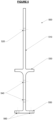
- FIG. 5 illustrates a one-piece cell divider 500, in accordance with some embodiments of the present invention.
- the one-piece cell divider 500 may be a single unit that replaces a lower support member and cell partition (or cell divider) from earlier systems.
- the one-piece cell divider 500 may therefore comprise an upper portion 510 that acts as a cell divider (or partition), and a lower portion that supports the porous plate. Porous plate may sit on surface 530, and may be affixed thereto.
- upper portion 510 may comprise one or more holes 520 configured to receive tie-rods or other devices to for additional support.
- the lower portion may further comprise one or more holes 540, and may also comprise a bottom surface, which in turn may comprise one or more holes 560 for attachment.
- Such one-piece cell divider 500 may be used in addition to the more traditional multiple piece lower support members and cell partitions. Note that the one-piece cell divider 500 may also comprise an integral anchoring device formed into the cell divider, rather than requiring a separate bolt-on angle.
- a solid partition may be installed once every 1.22 m (4 feet).
- the porous plates may be sized to fit between these solid partitions.
- Lower partitions may still be present once every 20.32 cm or 30.48 cm (8" or 12"), (depending on the design). This may also result in simpler installation and potentially less labor.
- the underdrain may now be installed using self-drilling / self-tapping screws. Previous designs often required a threaded stud that had to be located prior to installation of the porous plates and was secured using nuts and washers on the threaded stud. Easier maintenance is also to be expected.
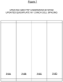
- Figure 8 illustrates an exemplary assembly of the cell partitions.
- the one-piece cell divider may be used every fourth divider.
- the remaining parts between the 1.22 m (four-foot) span may comprise a two or three-part support design comprising a lower beam, saddle, and cell sheet.
- One-piece cell dividers 810 may be used, along with more traditional multiple piece support and dividers 820. It can be seen from Figure 8 that porous plates 830A, 830B, 830C may be positioned between the one-piece cell dividers 810, and may be supported by the traditional multiple piece support and dividers 820. Such an arrangement prevents media leakage between areas bordered by the one-piece cell dividers 810.
- Figure 9 illustrates an exemplary system where every fourth divider is a one-piece cell divider.
- the remaining parts between the 1.22m (four-foot) span may comprise a two or three-part support design comprising a lower beam, saddle, and cell sheet.
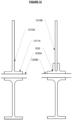
- Figure 10 illustrates how, in accordance with some embodiments of the present invention, a one-piece cell divider may be used.
- One-piece divider 1010 may be bolted or attached to baseplate 1040 via a bolt, screw, or other fastener 1070, and held in place by tie-rod 1020.
- Porous plate 1030 may be held into place by using an angle 1050, attached by a screw, bolt, or other fastener 1060.
- the angle in Figure 10 may be omitted.
- one-piece divider 1110 may again be attached to a baseplate 1140 or other surface via fastener 1160.
- Tie-rod 1120 may again maintain the one-piece divider 1110 in a vertical or substantially vertical position.
- a fastener such as but not limited to a self-tapping screw
- 1150 may be used to attach porous plate 1130 to the divider 1110.
- Figure 13 illustrates an exemplary arrangement of multiple piece support and dividers and may be used between the one-piece cell dividers.
- flanges on cell partitions 1310 may be mounted to porous plate 1320 and lower support member 1330 by bolts or any other means of affixation in porous plate 1320.
- Stainless steel bars 1340 and 1350 or caulk beads may also be used.
- Mounting cell partitions 1310 to lower support member 1330 through porous plate 1320 may be beneficial in that the porous plate may span more than one cell and removes the need for caulking of the mount between the porous plate and the cell dividers, as in conventional systems.
- the various components used in constructing the invention may utilize any number of materials, such as FRP, all plastics, steel, etc.
- the porous plate may be made from plastics (such as but not limited to polyethylene), wood, steel, aluminum oxide, etc.
- the porous plate may also be replaced with some type of screen or mesh material.
Landscapes
- Chemical & Material Sciences (AREA)
- Chemical Kinetics & Catalysis (AREA)
- Engineering & Computer Science (AREA)
- Architecture (AREA)
- Water Supply & Treatment (AREA)
- Environmental & Geological Engineering (AREA)
- Hydrology & Water Resources (AREA)
- Organic Chemistry (AREA)
- Life Sciences & Earth Sciences (AREA)
- Civil Engineering (AREA)
- Structural Engineering (AREA)
- Filtration Of Liquid (AREA)
- Filtering Materials (AREA)
Claims (3)
- Drain de sortie à filtre (100, 300) pour supporter un média filtrant (105, 305) entre une pluralité de diviseurs formant au moins une cellule (102, 302), le drain de sortie à filtre comprenant :au moins une plaque poreuse (104, 830, 1030) pour supporter le média filtrant pour filtrer un fluide, la plaque poreuse enjambe au moins l'un des diviseurs ;la pluralité de diviseurs comprenant :
une pluralité de diviseurs de cellules en une pièce (500, 810, 1010), chaque diviseur de cellules en une pièce comprenant :une partie supérieure (510) qui est configurée pour servir de cloison entre deux cellules ;une première bride (530) configurée pour supporter la plaque poreuse ; etune partie inférieure (520) comprenant une surface inférieure configurée pour fixer le diviseur de cellules en une pièce à une plaque de base (1040),dans lequel la première bride est située entre la partie supérieure et la partie inférieure, et dans lequel la première bride est sensiblement perpendiculaire à la partie supérieure et à la partie inférieure ; etun ou plusieurs diviseurs à pièces multiples (820), chaque diviseur de cellules à pièces multiples comprenant une partie diviseur et un élément de support, l'élément de support se trouvant directement sous la partie diviseur, la partie diviseur et l'élément de support étant des composants distincts ;dans lequel la plaque poreuse est positionnée entre les séparateurs de cellules en une pièce et soutenue par les un ou plusieurs diviseurs à pièces multiples, etdans lequel le drain de sortie à filtre est assemblé sans utiliser de mastic isolant. - Drain de sortie à filtre selon la revendication 1, dans lequel la plaque poreuse est constituée de polyéthylène.
- Drain de sortie à filtre selon la revendication 1, dans lequel les diviseurs à pièces multiples comprennent en outre une partie en forme de selle, la partie en forme de selle étant disposée sur la plaque poreuse et recevant la partie diviseur dans une selle de la partie en forme de selle.
Applications Claiming Priority (2)
| Application Number | Priority Date | Filing Date | Title |
|---|---|---|---|
| US201762523399P | 2017-06-22 | 2017-06-22 | |
| PCT/EP2018/066733 WO2018234532A1 (fr) | 2017-06-22 | 2018-06-22 | Système de sous-drain utilisant des séparateurs de cellules en une pièce |
Publications (3)
| Publication Number | Publication Date |
|---|---|
| EP3641904A1 EP3641904A1 (fr) | 2020-04-29 |
| EP3641904B1 true EP3641904B1 (fr) | 2024-12-18 |
| EP3641904C0 EP3641904C0 (fr) | 2024-12-18 |
Family
ID=62986042
Family Applications (1)
| Application Number | Title | Priority Date | Filing Date |
|---|---|---|---|
| EP18743688.6A Active EP3641904B1 (fr) | 2017-06-22 | 2018-06-22 | Système de sous-drain utilisant des séparateurs de cellules en une pièce |
Country Status (7)
| Country | Link |
|---|---|
| US (1) | US11161063B2 (fr) |
| EP (1) | EP3641904B1 (fr) |
| KR (1) | KR20200042459A (fr) |
| AU (3) | AU2018287229A1 (fr) |
| CA (1) | CA3068118C (fr) |
| MX (1) | MX2019014421A (fr) |
| WO (1) | WO2018234532A1 (fr) |
Family Cites Families (6)
| Publication number | Priority date | Publication date | Assignee | Title |
|---|---|---|---|---|
| US4133766A (en) | 1977-03-11 | 1979-01-09 | Koppers Company, Inc. | Filter media support and containment system |
| US4619765A (en) * | 1984-10-10 | 1986-10-28 | Roberts Filter Manufacturing Company | Filter bottom construction |
| US5089130A (en) * | 1990-11-26 | 1992-02-18 | Infilco Degremont Inc. | Filter cell sheet installations |
| US5618421A (en) | 1996-02-26 | 1997-04-08 | Infilco Degremont Inc. | Underdrain filter plate installations in automatic backwash filter systems |
| US7090771B2 (en) | 2002-06-18 | 2006-08-15 | Infilco Degremont, Inc. | Filtration system underdrain |
| JP3959036B2 (ja) * | 2002-08-09 | 2007-08-15 | 日本原料株式会社 | 濾過装置 |
-
2018
- 2018-06-21 US US16/014,187 patent/US11161063B2/en active Active
- 2018-06-22 WO PCT/EP2018/066733 patent/WO2018234532A1/fr not_active Ceased
- 2018-06-22 AU AU2018287229A patent/AU2018287229A1/en not_active Abandoned
- 2018-06-22 KR KR1020207001792A patent/KR20200042459A/ko not_active Ceased
- 2018-06-22 EP EP18743688.6A patent/EP3641904B1/fr active Active
- 2018-06-22 MX MX2019014421A patent/MX2019014421A/es unknown
- 2018-06-22 CA CA3068118A patent/CA3068118C/fr active Active
-
2021
- 2021-11-30 AU AU2021277628A patent/AU2021277628A1/en not_active Abandoned
-
2024
- 2024-02-07 AU AU2024200762A patent/AU2024200762A1/en active Pending
Also Published As
| Publication number | Publication date |
|---|---|
| KR20200042459A (ko) | 2020-04-23 |
| CA3068118C (fr) | 2024-01-02 |
| AU2018287229A1 (en) | 2020-01-30 |
| US20190039000A1 (en) | 2019-02-07 |
| EP3641904A1 (fr) | 2020-04-29 |
| AU2024200762A1 (en) | 2024-02-29 |
| WO2018234532A1 (fr) | 2018-12-27 |
| MX2019014421A (es) | 2020-11-11 |
| CA3068118A1 (fr) | 2018-12-27 |
| AU2021277628A1 (en) | 2021-12-23 |
| US11161063B2 (en) | 2021-11-02 |
| EP3641904C0 (fr) | 2024-12-18 |
Similar Documents
| Publication | Publication Date | Title |
|---|---|---|
| US7138056B2 (en) | Filter underdrain system for backwash flow and method for measuring same | |
| JPS5825484B2 (ja) | 多セル式粒状材濾過装置 | |
| US7090771B2 (en) | Filtration system underdrain | |
| US9962633B2 (en) | Disk type filtering apparatus | |
| US12397247B2 (en) | Underdrain filtered water collection systems with winged screen diffusers | |
| CA3068118C (fr) | Systeme de sous-drain utilisant des separateurs de cellules en une piece | |
| US9987569B2 (en) | Underdrain for a filter system for filtering water or wastewater and a method of washing a filter system | |
| US6921481B2 (en) | Automatic backwash filter system | |
| US10016706B2 (en) | Disk type filtering apparatus | |
| US20130134086A1 (en) | Flume system for a filter system including at least one filter having a fitler bed that is periodically washed with liquid, gas or a bombination thereof | |
| KR200156598Y1 (ko) | 급속여과지의 하부집수장치 | |
| US20070080118A1 (en) | Filter assembly | |
| US6733670B2 (en) | Apparatus and method for rehabilitating a traveling bridge filter underdrain | |
| RU2205691C1 (ru) | Ионообменный фильтр | |
| US20180339246A1 (en) | Underdrain for a Filter System for Filtering Water or Wastewater and a Method of Washing a Filter System | |
| US7771597B2 (en) | Filter system | |
| KR100659401B1 (ko) | 급속 여과지의 집수장치 | |
| JP2013176730A (ja) | 複層式濾過装置のための濾過材洗浄装置及び濾過材洗浄方法 | |
| CN112337149B (zh) | 一种可连续运行的圆形悬浮过滤系统 | |
| KR100572352B1 (ko) | 하부집수장치의 개량보수구조 및 개량보수방법 | |
| JP2757956B2 (ja) | 移床式連続砂ろ過装置とその施工方法 | |
| CS239992B1 (cs) | Filtrační mezidno filtru 3 plovoucí filtrační vrstvou | |
| PL46144B1 (fr) | ||
| SE417907B (sv) | Filtersystem |
Legal Events
| Date | Code | Title | Description |
|---|---|---|---|
| STAA | Information on the status of an ep patent application or granted ep patent |
Free format text: STATUS: UNKNOWN |
|
| STAA | Information on the status of an ep patent application or granted ep patent |
Free format text: STATUS: THE INTERNATIONAL PUBLICATION HAS BEEN MADE |
|
| PUAI | Public reference made under article 153(3) epc to a published international application that has entered the european phase |
Free format text: ORIGINAL CODE: 0009012 |
|
| STAA | Information on the status of an ep patent application or granted ep patent |
Free format text: STATUS: REQUEST FOR EXAMINATION WAS MADE |
|
| 17P | Request for examination filed |
Effective date: 20200114 |
|
| AK | Designated contracting states |
Kind code of ref document: A1 Designated state(s): AL AT BE BG CH CY CZ DE DK EE ES FI FR GB GR HR HU IE IS IT LI LT LU LV MC MK MT NL NO PL PT RO RS SE SI SK SM TR |
|
| AX | Request for extension of the european patent |
Extension state: BA ME |
|
| DAV | Request for validation of the european patent (deleted) | ||
| DAX | Request for extension of the european patent (deleted) | ||
| STAA | Information on the status of an ep patent application or granted ep patent |
Free format text: STATUS: EXAMINATION IS IN PROGRESS |
|
| 17Q | First examination report despatched |
Effective date: 20211124 |
|
| P01 | Opt-out of the competence of the unified patent court (upc) registered |
Effective date: 20230521 |
|
| GRAP | Despatch of communication of intention to grant a patent |
Free format text: ORIGINAL CODE: EPIDOSNIGR1 |
|
| STAA | Information on the status of an ep patent application or granted ep patent |
Free format text: STATUS: GRANT OF PATENT IS INTENDED |
|
| INTG | Intention to grant announced |
Effective date: 20240624 |
|
| GRAJ | Information related to disapproval of communication of intention to grant by the applicant or resumption of examination proceedings by the epo deleted |
Free format text: ORIGINAL CODE: EPIDOSDIGR1 |
|
| STAA | Information on the status of an ep patent application or granted ep patent |
Free format text: STATUS: EXAMINATION IS IN PROGRESS |
|
| GRAP | Despatch of communication of intention to grant a patent |
Free format text: ORIGINAL CODE: EPIDOSNIGR1 |
|
| STAA | Information on the status of an ep patent application or granted ep patent |
Free format text: STATUS: GRANT OF PATENT IS INTENDED |
|
| INTC | Intention to grant announced (deleted) | ||
| GRAS | Grant fee paid |
Free format text: ORIGINAL CODE: EPIDOSNIGR3 |
|
| GRAA | (expected) grant |
Free format text: ORIGINAL CODE: 0009210 |
|
| STAA | Information on the status of an ep patent application or granted ep patent |
Free format text: STATUS: THE PATENT HAS BEEN GRANTED |
|
| INTG | Intention to grant announced |
Effective date: 20241016 |
|
| AK | Designated contracting states |
Kind code of ref document: B1 Designated state(s): AL AT BE BG CH CY CZ DE DK EE ES FI FR GB GR HR HU IE IS IT LI LT LU LV MC MK MT NL NO PL PT RO RS SE SI SK SM TR |
|
| REG | Reference to a national code |
Ref country code: GB Ref legal event code: FG4D |
|
| REG | Reference to a national code |
Ref country code: CH Ref legal event code: EP |
|
| REG | Reference to a national code |
Ref country code: DE Ref legal event code: R096 Ref document number: 602018077699 Country of ref document: DE |
|
| REG | Reference to a national code |
Ref country code: IE Ref legal event code: FG4D |
|
| U01 | Request for unitary effect filed |
Effective date: 20250108 |
|
| P04 | Withdrawal of opt-out of the competence of the unified patent court (upc) registered |
Free format text: CASE NUMBER: APP_2176/2025 Effective date: 20250114 |
|
| U07 | Unitary effect registered |
Designated state(s): AT BE BG DE DK EE FI FR IT LT LU LV MT NL PT RO SE SI Effective date: 20250116 |
|
| PG25 | Lapsed in a contracting state [announced via postgrant information from national office to epo] |
Ref country code: HR Free format text: LAPSE BECAUSE OF FAILURE TO SUBMIT A TRANSLATION OF THE DESCRIPTION OR TO PAY THE FEE WITHIN THE PRESCRIBED TIME-LIMIT Effective date: 20241218 |
|
| PG25 | Lapsed in a contracting state [announced via postgrant information from national office to epo] |
Ref country code: NO Free format text: LAPSE BECAUSE OF FAILURE TO SUBMIT A TRANSLATION OF THE DESCRIPTION OR TO PAY THE FEE WITHIN THE PRESCRIBED TIME-LIMIT Effective date: 20250318 |
|
| PG25 | Lapsed in a contracting state [announced via postgrant information from national office to epo] |
Ref country code: GR Free format text: LAPSE BECAUSE OF FAILURE TO SUBMIT A TRANSLATION OF THE DESCRIPTION OR TO PAY THE FEE WITHIN THE PRESCRIBED TIME-LIMIT Effective date: 20250319 |
|
| PG25 | Lapsed in a contracting state [announced via postgrant information from national office to epo] |
Ref country code: RS Free format text: LAPSE BECAUSE OF FAILURE TO SUBMIT A TRANSLATION OF THE DESCRIPTION OR TO PAY THE FEE WITHIN THE PRESCRIBED TIME-LIMIT Effective date: 20250318 |
|
| PG25 | Lapsed in a contracting state [announced via postgrant information from national office to epo] |
Ref country code: SM Free format text: LAPSE BECAUSE OF FAILURE TO SUBMIT A TRANSLATION OF THE DESCRIPTION OR TO PAY THE FEE WITHIN THE PRESCRIBED TIME-LIMIT Effective date: 20241218 |
|
| PG25 | Lapsed in a contracting state [announced via postgrant information from national office to epo] |
Ref country code: PL Free format text: LAPSE BECAUSE OF FAILURE TO SUBMIT A TRANSLATION OF THE DESCRIPTION OR TO PAY THE FEE WITHIN THE PRESCRIBED TIME-LIMIT Effective date: 20241218 |
|
| PG25 | Lapsed in a contracting state [announced via postgrant information from national office to epo] |
Ref country code: ES Free format text: LAPSE BECAUSE OF FAILURE TO SUBMIT A TRANSLATION OF THE DESCRIPTION OR TO PAY THE FEE WITHIN THE PRESCRIBED TIME-LIMIT Effective date: 20241218 |
|
| PG25 | Lapsed in a contracting state [announced via postgrant information from national office to epo] |
Ref country code: IS Free format text: LAPSE BECAUSE OF FAILURE TO SUBMIT A TRANSLATION OF THE DESCRIPTION OR TO PAY THE FEE WITHIN THE PRESCRIBED TIME-LIMIT Effective date: 20250418 |
|
| PG25 | Lapsed in a contracting state [announced via postgrant information from national office to epo] |
Ref country code: SK Free format text: LAPSE BECAUSE OF FAILURE TO SUBMIT A TRANSLATION OF THE DESCRIPTION OR TO PAY THE FEE WITHIN THE PRESCRIBED TIME-LIMIT Effective date: 20241218 |
|
| PG25 | Lapsed in a contracting state [announced via postgrant information from national office to epo] |
Ref country code: CZ Free format text: LAPSE BECAUSE OF FAILURE TO SUBMIT A TRANSLATION OF THE DESCRIPTION OR TO PAY THE FEE WITHIN THE PRESCRIBED TIME-LIMIT Effective date: 20241218 |
|
| U20 | Renewal fee for the european patent with unitary effect paid |
Year of fee payment: 8 Effective date: 20250628 |
|
| PLBE | No opposition filed within time limit |
Free format text: ORIGINAL CODE: 0009261 |
|
| STAA | Information on the status of an ep patent application or granted ep patent |
Free format text: STATUS: NO OPPOSITION FILED WITHIN TIME LIMIT |
|
| REG | Reference to a national code |
Ref country code: CH Ref legal event code: L10 Free format text: ST27 STATUS EVENT CODE: U-0-0-L10-L00 (AS PROVIDED BY THE NATIONAL OFFICE) Effective date: 20251029 |
|
| 26N | No opposition filed |
Effective date: 20250919 |
|
| REG | Reference to a national code |
Ref country code: CH Ref legal event code: H13 Free format text: ST27 STATUS EVENT CODE: U-0-0-H10-H13 (AS PROVIDED BY THE NATIONAL OFFICE) Effective date: 20260127 |
|
| PG25 | Lapsed in a contracting state [announced via postgrant information from national office to epo] |
Ref country code: MC Free format text: LAPSE BECAUSE OF FAILURE TO SUBMIT A TRANSLATION OF THE DESCRIPTION OR TO PAY THE FEE WITHIN THE PRESCRIBED TIME-LIMIT Effective date: 20241218 |
|
| GBPC | Gb: european patent ceased through non-payment of renewal fee |
Effective date: 20250622 |
|
| PG25 | Lapsed in a contracting state [announced via postgrant information from national office to epo] |
Ref country code: GB Free format text: LAPSE BECAUSE OF NON-PAYMENT OF DUE FEES Effective date: 20250622 |
|
| PG25 | Lapsed in a contracting state [announced via postgrant information from national office to epo] |
Ref country code: IE Free format text: LAPSE BECAUSE OF NON-PAYMENT OF DUE FEES Effective date: 20250622 |
|
| PG25 | Lapsed in a contracting state [announced via postgrant information from national office to epo] |
Ref country code: CH Free format text: LAPSE BECAUSE OF NON-PAYMENT OF DUE FEES Effective date: 20250630 |