EP3642094B1 - Attelage de véhicules ferroviaires rigide en roulis - Google Patents
Attelage de véhicules ferroviaires rigide en roulis Download PDFInfo
- Publication number
- EP3642094B1 EP3642094B1 EP18785844.4A EP18785844A EP3642094B1 EP 3642094 B1 EP3642094 B1 EP 3642094B1 EP 18785844 A EP18785844 A EP 18785844A EP 3642094 B1 EP3642094 B1 EP 3642094B1
- Authority
- EP
- European Patent Office
- Prior art keywords
- rail vehicle
- coupling
- bracket
- vehicle coupling
- axle
- Prior art date
- Legal status (The legal status is an assumption and is not a legal conclusion. Google has not performed a legal analysis and makes no representation as to the accuracy of the status listed.)
- Active
Links
Images

Classifications
-
- B—PERFORMING OPERATIONS; TRANSPORTING
- B61—RAILWAYS
- B61G—COUPLINGS; DRAUGHT AND BUFFING APPLIANCES
- B61G5/00—Couplings for special purposes not otherwise provided for
- B61G5/02—Couplings for special purposes not otherwise provided for for coupling articulated trains, locomotives and tenders or the bogies of a vehicle; Coupling by means of a single coupling bar; Couplings preventing or limiting relative lateral movement of vehicles
Definitions
- the invention relates to a roll-resistant rail vehicle coupling for coupling a rail vehicle to a rail vehicle in sedan-style construction.
- Typical passenger rail vehicles have two bogies and can be coupled with other vehicles.
- special train configurations do not require operational separability of the vehicle composition, so that other vehicle concepts can be used.
- sedan trolleys are used, which do not have their own chassis but are carried by the neighboring vehicles.
- a specific coupling is provided between a conventional and a sedan trolley, which transmits the operating and weight forces and which ensures the necessary mobility for cornering, hilltop and tub travel.
- Ball joints (spherical bearings) or elastomer layer spring bearings are particularly well suited for this.
- the coupled vehicles are connected by means of a link, the link being articulated to each vehicle and preventing the vehicles from tilting towards one another, ie blocking a degree of freedom of movement of the ball joint.
- This link is typically arranged in the roof space of the vehicle, as a result of which the forces to be transmitted via the link are reduced due to the law of levers compared to an arrangement in the underframe area. In the case of small vehicles with an atypically small cross-section, however, such an arrangement is not possible, so that the sedan chair principle may not be applicable.
- Ball joints for connecting rail vehicles are known from the prior art, as disclosed in the German utility model DE20004850U1 such a coupling, measures have been taken to simplify the assembly of a coupling bolt.
- a coupling bolt is centered on both sides to form truncated conical pins, which simplifies the closing of a coupling.
- the invention is therefore based on the object of specifying a stiff rail vehicle coupling for coupling a rail vehicle to a rail vehicle in sedan-style construction, in which the degree of freedom of rotation around the longitudinal axis of the rail vehicle coupling and thus around the longitudinal axis of the rail vehicles to be coupled is blocked.
- a roll-resistant rail vehicle coupling for the connection of a rail vehicle with a rail vehicle is constructed in sedan-style construction, which has a joint eye set up for detachable connection with one of the two rail vehicles and a joint fork set up for detachable connection with the other of the two rail vehicles as well as a horizontally aligned Axis which is connected to the joint fork and which penetrates a spherical bearing connected to the joint eye, the joint eye including a vertically oriented stub axle whose axis of rotation runs through the pivot point of the spherical bearing, this stub axle engaging rotatably in a bracket, and the ends the axis are rotatably mounted in the bracket.
- the joint eye of a rail vehicle coupling which connects the rail vehicles to be coupled by means of a spherical bearing, is to be equipped with an axle stub.
- the axis of rotation of this stub axle is to be aligned vertically so that it runs through the pivot point of the spherical bearing.
- This stub axle is rotatably mounted in a bracket.
- the bracket is designed in such a way that it has a bearing for the axle, which penetrates the spherical bearing and thus establishes the connection between the rail vehicles.
- the axis is lengthened at its ends so that it protrudes beyond the joint fork.
- the vertically oriented stub axle should preferably be arranged downwards, i.e. in the direction of the track bed, since unused installation space is used in this way and more space remains above the rail vehicle coupling, especially for the passenger compartment.
- a preferred embodiment of the invention provides for the bracket to be constructed in several parts, in particular in three parts, since in this way a particularly simple assembly of the bracket can take place.
- the rigid rail vehicle coupling can be mounted on the vehicles to be coupled and closed with the axle and the bracket can then be mounted on it. Otherwise, the axle would have to be assembled in a final work step, the bracket in addition to the joint fork and the joint eye would have to be positioned exactly and the force of the axle pressed into the spherical bearing would be suitably supported.
- This assembly sequence is much more complex than one to provide multi-part bracket and to assemble the bracket after mounting the axis in individual parts and to releasably connect these parts to one another.
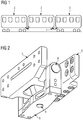
- Fig. 1 shows an example and schematically a train composition with a sedan trolley.
- a train made up of three vehicles is shown, a rail vehicle in sedan-style construction 2 being coupled between two conventional rail vehicles 3.
- a rail vehicle coupling 1 according to the invention is arranged between the rail vehicle in sedan-style construction 2 and the right rail vehicle 1.
- the further coupling of the rail vehicle in sedan design 2 is of a different embodiment, it only has to transmit the weight and operating forces between these vehicles, a ball joint with three degrees of freedom of rotation being able to be used there the rail vehicle coupling 1 at the further end of the vehicle prevents the rail vehicle in sedan-style construction 2 from rolling.
- the rail vehicle in sedan-style construction 2 and the right-hand coupled conventional rail vehicle 3 can therefore only move together about their respective longitudinal axis.
- FIG. 2 shows an example and schematically a rail vehicle coupling.
- a rail vehicle coupling 1 is shown in its installation position, which comprises a joint eye 4 and a joint fork 5.
- These components 4, 5 are each designed for a detachable connection to the car body of a rail vehicle and have holes for screw fastenings as corresponding fastening means. Other fasteners, such as screws, are in Fig. 1 not shown to simplify the illustration.
- the joint eye 4 is fitted with a spherical bearing 7 (in Fig. 1 not visible), through which an axis 6 penetrates, which is connected to the joint fork 5. In this way, there is a connection between the joint fork 5 and the joint eye 6, which blocks all translational degrees of freedom and thus transmits all operating forces in all directions.
- the spherical bearing 7 ensures freedom of all three degrees of freedom of rotation, which is necessary for a movement about the vertical axis and the transverse axis.
- the degree of freedom around the longitudinal axis cannot remain unblocked for driving operation in order to prevent excessive swaying and even tipping of the rail vehicle in sedan-style construction 2.
- the two ends of the axle 6 are designed to be elongated so that they protrude from the joint fork 5 and are each connected to a bracket 9 in a rotatable manner.
- the bracket 9 is essentially U-shaped and has corresponding bores with bearings for receiving the ends of the axle 6.
- the joint eye is equipped with a vertically aligned stub axle 8, the axis of rotation of which is directed through the pivot point of the spherical bearing 7 and which is also rotatably mounted in the bracket 9.
- the bracket 9 locks the rail vehicle coupling 1 by the degree of freedom of the longitudinal axis, so that the two rail vehicles 2, 3 cannot roll to one another.
- the bracket 9 is designed in three parts, as a result of which assembly is significantly simplified.
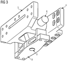
- Fig. 3 shows by way of example and schematically a rail vehicle coupling with a dismantled bracket.
- the rail vehicle coupling 1 is off Fig. 1 shown, wherein the two vertical sections of the U-shaped bracket 9 are removed. In this way, the axis 6, which is extended beyond the joint fork 5, can be clearly seen.
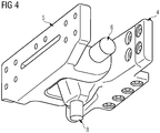
- Fig. 4 shows an example and schematically a rail vehicle coupling without a bracket.
- the rail vehicle coupling 1 is off Fig. 1 shown, the bracket 9 has been completely removed.
- the vertically oriented stub axle 8, which is part of the joint eye, can also be seen in this way.
- Fig. 5 shows an example and schematically a hinge eye of a rail vehicle coupling.
- the articulated eye 4 of a rail vehicle coupling 1 is shown, which comprises a stub axle 8 oriented vertically downwards and in which a spherical bearing 7 is introduced.
- the axis 6 is guided through this spherical bearing 7.
Landscapes
- Engineering & Computer Science (AREA)
- Mechanical Engineering (AREA)
- Pivots And Pivotal Connections (AREA)
- Automatic Cycles, And Cycles In General (AREA)
Claims (3)
- Accouplement de véhicule ferroviaire (1) rigide au roulis destiné à l'accouplement d'un véhicule ferroviaire (3) à un véhicule ferroviaire à conception type palanquin (2), comportant un œillet articulé (4) apte à être relié de façon amovible à l'un des deux véhicules ferroviaires (2, 3) et une fourche articulée (5) apte à être reliée de façon amovible à l'autre des deux véhicules ferroviaires (2, 3), ainsi qu'un axe (6) à orientation horizontale relié à la fourche articulée (5) et traversant un palier sphérique (7) relié à l'œillet articulé (4),
caractérisé en ce que
l'œillet articulé (4) comprend un bout d'essieu (8) à orientation verticale dont l'axe de rotation passe par le centre de rotation du palier sphérique (7), ledit bout d'essieu (8) prenant, mobile en rotation, dans un support (9), les extrémités de l'essieu (6) étant montées mobile en rotation dans le support (9). - Accouplement de véhicule ferroviaire (1) rigide au roulis selon la revendication 1,
caractérisé en ce que,
en position de montage de l'accouplement de véhicule ferroviaire, le bout d'essieu (8) est orienté en direction du ballast. - Accouplement de véhicule ferroviaire (1) selon la revendication 1 ou 2,
caractérisé en ce que
le support (9) est constitué par plusieurs composants reliés entre eux de façon amovible.
Applications Claiming Priority (2)
| Application Number | Priority Date | Filing Date | Title |
|---|---|---|---|
| ATA50828/2017A AT519744B1 (de) | 2017-09-27 | 2017-09-27 | Wanksteife Schienenfahrzeugkupplung |
| PCT/EP2018/076060 WO2019063587A1 (fr) | 2017-09-27 | 2018-09-26 | Attelage de véhicules ferroviaires rigide en roulis |
Publications (2)
| Publication Number | Publication Date |
|---|---|
| EP3642094A1 EP3642094A1 (fr) | 2020-04-29 |
| EP3642094B1 true EP3642094B1 (fr) | 2021-06-09 |
Family
ID=63787582
Family Applications (1)
| Application Number | Title | Priority Date | Filing Date |
|---|---|---|---|
| EP18785844.4A Active EP3642094B1 (fr) | 2017-09-27 | 2018-09-26 | Attelage de véhicules ferroviaires rigide en roulis |
Country Status (4)
| Country | Link |
|---|---|
| EP (1) | EP3642094B1 (fr) |
| CN (1) | CN111108032B (fr) |
| AT (1) | AT519744B1 (fr) |
| WO (1) | WO2019063587A1 (fr) |
Family Cites Families (9)
| Publication number | Priority date | Publication date | Assignee | Title |
|---|---|---|---|---|
| FR1512601A (fr) * | 1966-12-30 | 1968-02-09 | Venissieux Atel | Dispositif de liaison entre deux parties d'un véhicule ferroviaire et un bogie intermédiaire sur lequel elles prennent appui |
| FR2695612B1 (fr) * | 1992-09-11 | 1994-10-14 | Alsthom Gec | Dispositif d'accrochage du type à rotule, en particulier pour véhicules ferroviaires. |
| US5520295A (en) * | 1994-07-18 | 1996-05-28 | Hansen Inc. | Articulated rail car connector |
| DE19919536A1 (de) * | 1999-04-29 | 2000-11-02 | Alstom Lhb Gmbh | Gelenkkupplung für Fahrzeugeinheiten von Schienenfahrzeugen |
| DE10021967A1 (de) * | 2000-05-05 | 2001-11-08 | Scharfenbergkupplung Gmbh & Co | Vorrichtung zur gelenkigen Verbindung von Wagenkästen eines mehrgliedrigen Schienenfahrzeuges |
| ATE422450T1 (de) * | 2006-11-22 | 2009-02-15 | Voith Patent Gmbh | Kupplungsanlenkung für einen wagenkasten eines mehrgliedrigen fahrzeuges |
| ES2731910T3 (es) * | 2014-12-03 | 2019-11-19 | Huebner Gmbh & Co Kg | Sector de techo entre dos componentes de vehículo conectados entre sí de manera articulada |
| CN105460033B (zh) * | 2015-11-25 | 2017-08-25 | 长春轨道客车股份有限公司 | 一种用于动车组相邻车体之间可降低地板高度的走行装置 |
| CN206288028U (zh) * | 2016-11-15 | 2017-06-30 | 中车长春轨道客车股份有限公司 | 轨道车辆中高地板铰接车铰接装置 |
-
2017
- 2017-09-27 AT ATA50828/2017A patent/AT519744B1/de active
-
2018
- 2018-09-26 CN CN201880063245.5A patent/CN111108032B/zh active Active
- 2018-09-26 EP EP18785844.4A patent/EP3642094B1/fr active Active
- 2018-09-26 WO PCT/EP2018/076060 patent/WO2019063587A1/fr not_active Ceased
Also Published As
| Publication number | Publication date |
|---|---|
| CN111108032A (zh) | 2020-05-05 |
| WO2019063587A1 (fr) | 2019-04-04 |
| EP3642094A1 (fr) | 2020-04-29 |
| CN111108032B (zh) | 2021-09-24 |
| AT519744A4 (de) | 2018-10-15 |
| AT519744B1 (de) | 2018-10-15 |
Similar Documents
| Publication | Publication Date | Title |
|---|---|---|
| EP2084047B1 (fr) | Dispositif de liaison mécanique de véhicules | |
| DE4404878C1 (de) | Gelenkverbindung für zwei Teileinheiten eines Fahrzeugs | |
| EP2167362B1 (fr) | Véhicule à caisses articulées | |
| EP0838386B1 (fr) | Véhicule ferroviaire avec au moins un train de roulement et train de roulement pour un tel véhicule | |
| EP3504096B1 (fr) | Véhicule articulé | |
| EP3642094B1 (fr) | Attelage de véhicules ferroviaires rigide en roulis | |
| EP2061690B1 (fr) | Fixation pour un guide d'essieu d'un véhicule ferroviaire | |
| DE490825C (de) | Wagen fuer Eisenbahnen, Strassenbahnen, Schnellbahnen u. dgl., insbesondere fuer Gelenkwagenzuege | |
| DE102014220775B4 (de) | Schienenfahrzeug in Aufliegerausführung | |
| DE3924642C2 (fr) | ||
| AT518809B1 (de) | Vorrichtung zur Blockierung der Torsionsbewegung zwischen zwei gekuppelten Schienenfahrzeugen | |
| AT509524B1 (de) | Fahrwerksaufnahmerahmen | |
| EP3390197B1 (fr) | Accouplement de véhicule ferroviaire | |
| EP3109121B1 (fr) | Bati tournant pour vehicules ferroviaire a plusieurs articulations et vehicules ferroviaire a plusieurs articulations | |
| DE1077244B (de) | Zwei- oder mehrteiliger Gliederzug, bei dem die Wagenenden auf je einer Einzelachse gelagert und in der Achsmitte zugleich auch gefuehrt sind | |
| DE102018130813A1 (de) | Fahrzeugsegment für ein mehrgliedriges schienenfahrzeug und schienenfahrzeug | |
| DE69611399T2 (de) | Schienenfahrzeuge für eine optimierte Ausnutzung des Lichtraumprofils von Bahngleisen | |
| DE69916710T2 (de) | Schienenfahrzeug mit seitlicher Verschiebung des Drehzapfens des Drehgestells | |
| DE29819951U1 (de) | Verbindung zwischen zwei Fahrzeugteilen eines Gelenkfahrzeuges | |
| DE2523136A1 (de) | Aufhaengevorrichtung fuer gondeln von haengebahnen | |
| DE1133749B (de) | Gelenkverbindung zwischen den Wagen einer nur aus zwei Wagen bestehenden Wageneinheit eines Schienengelenkzuges | |
| DE1109203B (de) | Schwerlastfahrzeug, insbesondere Schienenfahrzeug zum Transport von Wandertransformatoren | |
| DE1193981B (de) | Strassenbahngelenkwagen | |
| DE1103373B (de) | Dreiteiliges Schienen-Gliederfahrzeug | |
| DE2548204A1 (de) | Kombinierte kupplungs- und puffereinrichtung fuer ein schienenfahrzeug |
Legal Events
| Date | Code | Title | Description |
|---|---|---|---|
| STAA | Information on the status of an ep patent application or granted ep patent |
Free format text: STATUS: UNKNOWN |
|
| STAA | Information on the status of an ep patent application or granted ep patent |
Free format text: STATUS: THE INTERNATIONAL PUBLICATION HAS BEEN MADE |
|
| PUAI | Public reference made under article 153(3) epc to a published international application that has entered the european phase |
Free format text: ORIGINAL CODE: 0009012 |
|
| STAA | Information on the status of an ep patent application or granted ep patent |
Free format text: STATUS: REQUEST FOR EXAMINATION WAS MADE |
|
| 17P | Request for examination filed |
Effective date: 20200122 |
|
| AK | Designated contracting states |
Kind code of ref document: A1 Designated state(s): AL AT BE BG CH CY CZ DE DK EE ES FI FR GB GR HR HU IE IS IT LI LT LU LV MC MK MT NL NO PL PT RO RS SE SI SK SM TR |
|
| AX | Request for extension of the european patent |
Extension state: BA ME |
|
| DAV | Request for validation of the european patent (deleted) | ||
| DAX | Request for extension of the european patent (deleted) | ||
| GRAP | Despatch of communication of intention to grant a patent |
Free format text: ORIGINAL CODE: EPIDOSNIGR1 |
|
| STAA | Information on the status of an ep patent application or granted ep patent |
Free format text: STATUS: GRANT OF PATENT IS INTENDED |
|
| INTG | Intention to grant announced |
Effective date: 20210202 |
|
| GRAS | Grant fee paid |
Free format text: ORIGINAL CODE: EPIDOSNIGR3 |
|
| GRAA | (expected) grant |
Free format text: ORIGINAL CODE: 0009210 |
|
| STAA | Information on the status of an ep patent application or granted ep patent |
Free format text: STATUS: THE PATENT HAS BEEN GRANTED |
|
| AK | Designated contracting states |
Kind code of ref document: B1 Designated state(s): AL AT BE BG CH CY CZ DE DK EE ES FI FR GB GR HR HU IE IS IT LI LT LU LV MC MK MT NL NO PL PT RO RS SE SI SK SM TR |
|
| REG | Reference to a national code |
Ref country code: GB Ref legal event code: FG4D Free format text: NOT ENGLISH |
|
| REG | Reference to a national code |
Ref country code: CH Ref legal event code: EP Ref country code: AT Ref legal event code: REF Ref document number: 1400243 Country of ref document: AT Kind code of ref document: T Effective date: 20210615 |
|
| REG | Reference to a national code |
Ref country code: DE Ref legal event code: R096 Ref document number: 502018005687 Country of ref document: DE |
|
| REG | Reference to a national code |
Ref country code: IE Ref legal event code: FG4D Free format text: LANGUAGE OF EP DOCUMENT: GERMAN |
|
| REG | Reference to a national code |
Ref country code: LT Ref legal event code: MG9D |
|
| PG25 | Lapsed in a contracting state [announced via postgrant information from national office to epo] |
Ref country code: FI Free format text: LAPSE BECAUSE OF FAILURE TO SUBMIT A TRANSLATION OF THE DESCRIPTION OR TO PAY THE FEE WITHIN THE PRESCRIBED TIME-LIMIT Effective date: 20210609 Ref country code: HR Free format text: LAPSE BECAUSE OF FAILURE TO SUBMIT A TRANSLATION OF THE DESCRIPTION OR TO PAY THE FEE WITHIN THE PRESCRIBED TIME-LIMIT Effective date: 20210609 Ref country code: LT Free format text: LAPSE BECAUSE OF FAILURE TO SUBMIT A TRANSLATION OF THE DESCRIPTION OR TO PAY THE FEE WITHIN THE PRESCRIBED TIME-LIMIT Effective date: 20210609 Ref country code: BG Free format text: LAPSE BECAUSE OF FAILURE TO SUBMIT A TRANSLATION OF THE DESCRIPTION OR TO PAY THE FEE WITHIN THE PRESCRIBED TIME-LIMIT Effective date: 20210909 |
|
| REG | Reference to a national code |
Ref country code: NL Ref legal event code: MP Effective date: 20210609 |
|
| PG25 | Lapsed in a contracting state [announced via postgrant information from national office to epo] |
Ref country code: SE Free format text: LAPSE BECAUSE OF FAILURE TO SUBMIT A TRANSLATION OF THE DESCRIPTION OR TO PAY THE FEE WITHIN THE PRESCRIBED TIME-LIMIT Effective date: 20210609 Ref country code: RS Free format text: LAPSE BECAUSE OF FAILURE TO SUBMIT A TRANSLATION OF THE DESCRIPTION OR TO PAY THE FEE WITHIN THE PRESCRIBED TIME-LIMIT Effective date: 20210609 Ref country code: LV Free format text: LAPSE BECAUSE OF FAILURE TO SUBMIT A TRANSLATION OF THE DESCRIPTION OR TO PAY THE FEE WITHIN THE PRESCRIBED TIME-LIMIT Effective date: 20210609 Ref country code: NO Free format text: LAPSE BECAUSE OF FAILURE TO SUBMIT A TRANSLATION OF THE DESCRIPTION OR TO PAY THE FEE WITHIN THE PRESCRIBED TIME-LIMIT Effective date: 20210909 Ref country code: GR Free format text: LAPSE BECAUSE OF FAILURE TO SUBMIT A TRANSLATION OF THE DESCRIPTION OR TO PAY THE FEE WITHIN THE PRESCRIBED TIME-LIMIT Effective date: 20210910 |
|
| PG25 | Lapsed in a contracting state [announced via postgrant information from national office to epo] |
Ref country code: SK Free format text: LAPSE BECAUSE OF FAILURE TO SUBMIT A TRANSLATION OF THE DESCRIPTION OR TO PAY THE FEE WITHIN THE PRESCRIBED TIME-LIMIT Effective date: 20210609 Ref country code: ES Free format text: LAPSE BECAUSE OF FAILURE TO SUBMIT A TRANSLATION OF THE DESCRIPTION OR TO PAY THE FEE WITHIN THE PRESCRIBED TIME-LIMIT Effective date: 20210609 Ref country code: EE Free format text: LAPSE BECAUSE OF FAILURE TO SUBMIT A TRANSLATION OF THE DESCRIPTION OR TO PAY THE FEE WITHIN THE PRESCRIBED TIME-LIMIT Effective date: 20210609 Ref country code: CZ Free format text: LAPSE BECAUSE OF FAILURE TO SUBMIT A TRANSLATION OF THE DESCRIPTION OR TO PAY THE FEE WITHIN THE PRESCRIBED TIME-LIMIT Effective date: 20210609 Ref country code: PT Free format text: LAPSE BECAUSE OF FAILURE TO SUBMIT A TRANSLATION OF THE DESCRIPTION OR TO PAY THE FEE WITHIN THE PRESCRIBED TIME-LIMIT Effective date: 20211011 Ref country code: NL Free format text: LAPSE BECAUSE OF FAILURE TO SUBMIT A TRANSLATION OF THE DESCRIPTION OR TO PAY THE FEE WITHIN THE PRESCRIBED TIME-LIMIT Effective date: 20210609 Ref country code: RO Free format text: LAPSE BECAUSE OF FAILURE TO SUBMIT A TRANSLATION OF THE DESCRIPTION OR TO PAY THE FEE WITHIN THE PRESCRIBED TIME-LIMIT Effective date: 20210609 Ref country code: SM Free format text: LAPSE BECAUSE OF FAILURE TO SUBMIT A TRANSLATION OF THE DESCRIPTION OR TO PAY THE FEE WITHIN THE PRESCRIBED TIME-LIMIT Effective date: 20210609 |
|
| PG25 | Lapsed in a contracting state [announced via postgrant information from national office to epo] |
Ref country code: PL Free format text: LAPSE BECAUSE OF FAILURE TO SUBMIT A TRANSLATION OF THE DESCRIPTION OR TO PAY THE FEE WITHIN THE PRESCRIBED TIME-LIMIT Effective date: 20210609 |
|
| REG | Reference to a national code |
Ref country code: DE Ref legal event code: R097 Ref document number: 502018005687 Country of ref document: DE |
|
| PLBE | No opposition filed within time limit |
Free format text: ORIGINAL CODE: 0009261 |
|
| STAA | Information on the status of an ep patent application or granted ep patent |
Free format text: STATUS: NO OPPOSITION FILED WITHIN TIME LIMIT |
|
| PG25 | Lapsed in a contracting state [announced via postgrant information from national office to epo] |
Ref country code: DK Free format text: LAPSE BECAUSE OF FAILURE TO SUBMIT A TRANSLATION OF THE DESCRIPTION OR TO PAY THE FEE WITHIN THE PRESCRIBED TIME-LIMIT Effective date: 20210609 |
|
| 26N | No opposition filed |
Effective date: 20220310 |
|
| REG | Reference to a national code |
Ref country code: BE Ref legal event code: MM Effective date: 20210930 |
|
| PG25 | Lapsed in a contracting state [announced via postgrant information from national office to epo] |
Ref country code: MC Free format text: LAPSE BECAUSE OF FAILURE TO SUBMIT A TRANSLATION OF THE DESCRIPTION OR TO PAY THE FEE WITHIN THE PRESCRIBED TIME-LIMIT Effective date: 20210609 Ref country code: AL Free format text: LAPSE BECAUSE OF FAILURE TO SUBMIT A TRANSLATION OF THE DESCRIPTION OR TO PAY THE FEE WITHIN THE PRESCRIBED TIME-LIMIT Effective date: 20210609 |
|
| PG25 | Lapsed in a contracting state [announced via postgrant information from national office to epo] |
Ref country code: LU Free format text: LAPSE BECAUSE OF NON-PAYMENT OF DUE FEES Effective date: 20210926 Ref country code: IT Free format text: LAPSE BECAUSE OF FAILURE TO SUBMIT A TRANSLATION OF THE DESCRIPTION OR TO PAY THE FEE WITHIN THE PRESCRIBED TIME-LIMIT Effective date: 20210609 Ref country code: IE Free format text: LAPSE BECAUSE OF NON-PAYMENT OF DUE FEES Effective date: 20210926 Ref country code: BE Free format text: LAPSE BECAUSE OF NON-PAYMENT OF DUE FEES Effective date: 20210930 |
|
| PG25 | Lapsed in a contracting state [announced via postgrant information from national office to epo] |
Ref country code: CY Free format text: LAPSE BECAUSE OF FAILURE TO SUBMIT A TRANSLATION OF THE DESCRIPTION OR TO PAY THE FEE WITHIN THE PRESCRIBED TIME-LIMIT Effective date: 20210609 |
|
| PG25 | Lapsed in a contracting state [announced via postgrant information from national office to epo] |
Ref country code: HU Free format text: LAPSE BECAUSE OF FAILURE TO SUBMIT A TRANSLATION OF THE DESCRIPTION OR TO PAY THE FEE WITHIN THE PRESCRIBED TIME-LIMIT; INVALID AB INITIO Effective date: 20180926 |
|
| PG25 | Lapsed in a contracting state [announced via postgrant information from national office to epo] |
Ref country code: MK Free format text: LAPSE BECAUSE OF FAILURE TO SUBMIT A TRANSLATION OF THE DESCRIPTION OR TO PAY THE FEE WITHIN THE PRESCRIBED TIME-LIMIT Effective date: 20210609 |
|
| PG25 | Lapsed in a contracting state [announced via postgrant information from national office to epo] |
Ref country code: TR Free format text: LAPSE BECAUSE OF FAILURE TO SUBMIT A TRANSLATION OF THE DESCRIPTION OR TO PAY THE FEE WITHIN THE PRESCRIBED TIME-LIMIT Effective date: 20210609 |
|
| PG25 | Lapsed in a contracting state [announced via postgrant information from national office to epo] |
Ref country code: MT Free format text: LAPSE BECAUSE OF FAILURE TO SUBMIT A TRANSLATION OF THE DESCRIPTION OR TO PAY THE FEE WITHIN THE PRESCRIBED TIME-LIMIT Effective date: 20210609 |
|
| PGFP | Annual fee paid to national office [announced via postgrant information from national office to epo] |
Ref country code: AT Payment date: 20250818 Year of fee payment: 8 Ref country code: FR Payment date: 20250915 Year of fee payment: 8 |
|
| REG | Reference to a national code |
Ref country code: CH Ref legal event code: U11 Free format text: ST27 STATUS EVENT CODE: U-0-0-U10-U11 (AS PROVIDED BY THE NATIONAL OFFICE) Effective date: 20251210 |
|
| PGFP | Annual fee paid to national office [announced via postgrant information from national office to epo] |
Ref country code: DE Payment date: 20251120 Year of fee payment: 8 |
|
| PGFP | Annual fee paid to national office [announced via postgrant information from national office to epo] |
Ref country code: GB Payment date: 20251002 Year of fee payment: 8 |
|
| PGFP | Annual fee paid to national office [announced via postgrant information from national office to epo] |
Ref country code: CH Payment date: 20251210 Year of fee payment: 8 |