EP3643163A2 - Dispositif de séparation permettant la réduction des émissions dans les stalles et stalle d'animaux - Google Patents
Dispositif de séparation permettant la réduction des émissions dans les stalles et stalle d'animaux Download PDFInfo
- Publication number
- EP3643163A2 EP3643163A2 EP19204251.3A EP19204251A EP3643163A2 EP 3643163 A2 EP3643163 A2 EP 3643163A2 EP 19204251 A EP19204251 A EP 19204251A EP 3643163 A2 EP3643163 A2 EP 3643163A2
- Authority
- EP
- European Patent Office
- Prior art keywords
- separation device
- drain
- less
- drainage
- endless belt
- Prior art date
- Legal status (The legal status is an assumption and is not a legal conclusion. Google has not performed a legal analysis and makes no representation as to the accuracy of the status listed.)
- Pending
Links
Images


Classifications
-
- A—HUMAN NECESSITIES
- A01—AGRICULTURE; FORESTRY; ANIMAL HUSBANDRY; HUNTING; TRAPPING; FISHING
- A01K—ANIMAL HUSBANDRY; AVICULTURE; APICULTURE; PISCICULTURE; FISHING; REARING OR BREEDING ANIMALS, NOT OTHERWISE PROVIDED FOR; NEW BREEDS OF ANIMALS
- A01K1/00—Housing animals; Equipment therefor
- A01K1/01—Removal of dung or urine ; Removal of manure from stables
-
- A—HUMAN NECESSITIES
- A01—AGRICULTURE; FORESTRY; ANIMAL HUSBANDRY; HUNTING; TRAPPING; FISHING
- A01K—ANIMAL HUSBANDRY; AVICULTURE; APICULTURE; PISCICULTURE; FISHING; REARING OR BREEDING ANIMALS, NOT OTHERWISE PROVIDED FOR; NEW BREEDS OF ANIMALS
- A01K1/00—Housing animals; Equipment therefor
- A01K1/01—Removal of dung or urine ; Removal of manure from stables
- A01K1/0103—Removal of dung or urine ; Removal of manure from stables of liquid manure
-
- A—HUMAN NECESSITIES
- A01—AGRICULTURE; FORESTRY; ANIMAL HUSBANDRY; HUNTING; TRAPPING; FISHING
- A01K—ANIMAL HUSBANDRY; AVICULTURE; APICULTURE; PISCICULTURE; FISHING; REARING OR BREEDING ANIMALS, NOT OTHERWISE PROVIDED FOR; NEW BREEDS OF ANIMALS
- A01K1/00—Housing animals; Equipment therefor
- A01K1/01—Removal of dung or urine ; Removal of manure from stables
- A01K1/0135—Removal of dung or urine ; Removal of manure from stables by means of conveyor belts
-
- B—PERFORMING OPERATIONS; TRANSPORTING
- B01—PHYSICAL OR CHEMICAL PROCESSES OR APPARATUS IN GENERAL
- B01D—SEPARATION
- B01D33/00—Filters with filtering elements which move during the filtering operation
- B01D33/04—Filters with filtering elements which move during the filtering operation with filtering bands or the like supported on cylinders which are impervious for filtering
-
- A—HUMAN NECESSITIES
- A01—AGRICULTURE; FORESTRY; ANIMAL HUSBANDRY; HUNTING; TRAPPING; FISHING
- A01K—ANIMAL HUSBANDRY; AVICULTURE; APICULTURE; PISCICULTURE; FISHING; REARING OR BREEDING ANIMALS, NOT OTHERWISE PROVIDED FOR; NEW BREEDS OF ANIMALS
- A01K1/00—Housing animals; Equipment therefor
-
- A—HUMAN NECESSITIES
- A01—AGRICULTURE; FORESTRY; ANIMAL HUSBANDRY; HUNTING; TRAPPING; FISHING
- A01K—ANIMAL HUSBANDRY; AVICULTURE; APICULTURE; PISCICULTURE; FISHING; REARING OR BREEDING ANIMALS, NOT OTHERWISE PROVIDED FOR; NEW BREEDS OF ANIMALS
- A01K1/00—Housing animals; Equipment therefor
- A01K1/01—Removal of dung or urine ; Removal of manure from stables
- A01K1/0128—Removal of dung or urine ; Removal of manure from stables by means of scrapers or the like moving continuously
-
- A—HUMAN NECESSITIES
- A01—AGRICULTURE; FORESTRY; ANIMAL HUSBANDRY; HUNTING; TRAPPING; FISHING
- A01K—ANIMAL HUSBANDRY; AVICULTURE; APICULTURE; PISCICULTURE; FISHING; REARING OR BREEDING ANIMALS, NOT OTHERWISE PROVIDED FOR; NEW BREEDS OF ANIMALS
- A01K1/00—Housing animals; Equipment therefor
- A01K1/015—Floor coverings, e.g. bedding-down sheets ; Stable floors
- A01K1/0151—Grids; Gratings; Slatted floors
-
- A—HUMAN NECESSITIES
- A01—AGRICULTURE; FORESTRY; ANIMAL HUSBANDRY; HUNTING; TRAPPING; FISHING
- A01K—ANIMAL HUSBANDRY; AVICULTURE; APICULTURE; PISCICULTURE; FISHING; REARING OR BREEDING ANIMALS, NOT OTHERWISE PROVIDED FOR; NEW BREEDS OF ANIMALS
- A01K1/00—Housing animals; Equipment therefor
- A01K1/02—Pigsties; Dog-kennels; Rabbit-hutches or the like
-
- B—PERFORMING OPERATIONS; TRANSPORTING
- B01—PHYSICAL OR CHEMICAL PROCESSES OR APPARATUS IN GENERAL
- B01D—SEPARATION
- B01D33/00—Filters with filtering elements which move during the filtering operation
- B01D33/056—Construction of filtering bands or supporting belts, e.g. devices for centering, mounting or sealing the filtering bands or the supporting belts
-
- B—PERFORMING OPERATIONS; TRANSPORTING
- B01—PHYSICAL OR CHEMICAL PROCESSES OR APPARATUS IN GENERAL
- B01D—SEPARATION
- B01D33/00—Filters with filtering elements which move during the filtering operation
- B01D33/44—Regenerating the filter material in the filter
- B01D33/46—Regenerating the filter material in the filter by scrapers, brushes nozzles or the like acting on the cake-side of the filtering element
- B01D33/466—Regenerating the filter material in the filter by scrapers, brushes nozzles or the like acting on the cake-side of the filtering element scrapers
-
- B—PERFORMING OPERATIONS; TRANSPORTING
- B01—PHYSICAL OR CHEMICAL PROCESSES OR APPARATUS IN GENERAL
- B01D—SEPARATION
- B01D33/00—Filters with filtering elements which move during the filtering operation
- B01D33/80—Accessories
- B01D33/801—Driving means, shaft packing systems or the like
-
- B—PERFORMING OPERATIONS; TRANSPORTING
- B01—PHYSICAL OR CHEMICAL PROCESSES OR APPARATUS IN GENERAL
- B01D—SEPARATION
- B01D33/00—Filters with filtering elements which move during the filtering operation
- B01D33/80—Accessories
- B01D33/804—Accessories integrally combined with devices for controlling the filtration
-
- A—HUMAN NECESSITIES
- A01—AGRICULTURE; FORESTRY; ANIMAL HUSBANDRY; HUNTING; TRAPPING; FISHING
- A01K—ANIMAL HUSBANDRY; AVICULTURE; APICULTURE; PISCICULTURE; FISHING; REARING OR BREEDING ANIMALS, NOT OTHERWISE PROVIDED FOR; NEW BREEDS OF ANIMALS
- A01K2227/00—Animals characterised by species
- A01K2227/10—Mammal
- A01K2227/108—Swine
Definitions
- the invention relates to a separation device for forming a stand area for livestock, in particular pigs, and for reducing emissions in stables, in particular in pig houses, an animal stall, in particular pig stall, and a method for separating faeces and urine in an animal stall.
- a slatted floor has a large number of slits, so that liquid and solid excrements of the animals kept on the slatted floor are disposed of through the slits.
- the waste is disposed of through the cracks and a subsequent discharge of the liquid and solid excrement in an area under the slatted floor.
- a mixture of solid and liquid excrement also known as manure, is created under the slatted floor.
- the problems result in particular from an ammonia load in the barn.
- Ammonia is formed from urea from animal excrement by means of hydrolysis, excess nitrogen is largely excreted by the farm animals in the urine in the form of urea and converted to ammonia by the enzyme urease.
- the urease enzyme is excreted in the faeces.
- Air washers that are known Acid baths remove dust and ammonia from the air.
- ammonia load inside the barn remains the same as it would be without the air wash, because only the air blown out of the barn is washed.
- An air wash only addresses the surroundings of the barn, but essentially not the climate inside the barn.
- Ammonia is a pungent-smelling, colorless and poisonous gas that irritates the mucous membranes of humans and animals and leads to tears.
- ammonia can cause irritating cough and nausea when inhaled.
- the animals within stables are increasingly provided with employment material, which can consist, for example, of natural materials, for example hay, straw, alfalfa, sawdust or compacts from the mentioned or other materials.
- employment material can consist, for example, of natural materials, for example hay, straw, alfalfa, sawdust or compacts from the mentioned or other materials.
- the materials made available on a slatted floor for example, faeces, urine and the occupational material mix, which subsequently turns into liquid manure and consequently leads to an increased amount of solid matter in the liquid manure.
- Such a liquid manure can lead to the liquid manure system at least no longer being able to perform its function in the intended manner or to fail.
- the manure is then, for example, no longer stirrable and / or pumpable and / or can no longer be used.
- Current husbandry systems that work with a liquid manure system have limits on the use of occupational material that is wasted by the animals.
- the DE 10 2016 013 326 A1 and the WO 2017/121864 A1 is known a stall with a waste area, the bottom of which is a conveyor belt.
- the conveyor belt has a certain inclination, so that the liquid excrement can run counter to a conveying direction of the droppings.
- the existing systems and methods for reducing ammonia pollution in animal houses offer various advantages, but further improvements are desirable. It is therefore an object of the present invention to provide a separation device for forming a standing area for livestock, in particular pigs, and for reducing emissions in stables, in particular in pig houses, an animal stall, in particular pig stall, and a method for separating faeces and urine in an animal stall which reduce or eliminate one or more of the disadvantages mentioned.
- it is an object of the invention to provide a solution which reduces the ammonia load within an animal house, in particular a pig house. It is also an object of the invention to provide a solution that is more reliable and / or robust.
- a separation device for forming a stand area for livestock, in particular pigs, and for reducing emissions in stables, in particular in pigs, comprising a base frame, a drainage element with two or more drainage channels, each of which has a drainage end, and shoulders between them one of the two or more drainage channels extends orthogonally to a drainage direction, a liquid-permeable endless belt with an upper run and a lower run, the drainage element being arranged on the base frame such that a drainage direction of the two or more drainage channels is directed in the direction of the drain end and the drain end is positioned in such a way that a liquid flowing out of it reaches a discharge cross channel, the discharge element being arranged between the upper run and the lower run, and wherein the upper run rests on at least one shoulder.
- the base frame preferably forms an at least partially closed border, in particular a closed border. It is further preferred that the base frame is designed as a support structure.
- the base frame can have suitable fastening elements in order to fasten the drain element.
- the base frame can have a support element, preferably have two or more support elements on which the drain element is arranged.
- the drainage channel preferably comprises means for conducting a liquid, in particular a liquid conductor. Furthermore, this can have a, preferably internal, tube.
- the drainage channel is preferably channel-shaped, which means in particular that it is designed as a tube half or a half pipe. Furthermore, the drainage channel can have a U-shaped and / or V-shaped profile. It is further preferred that the drainage channel is formed by a bent and / or drawn sheet.
- the drainage channel preferably consists of metal, in particular steel, in particular of a stainless steel, preferably stainless steel, or comprises this or these. Furthermore, the drainage channel preferably consists of plastic, in particular fiber composite plastic, or comprises it.
- the drain element has the two or more drain channels.
- a drainage channel is to be understood in particular as an element through which a liquid can flow.
- the gutter is preferably a narrow and / or elongated element.
- the drainage channels are open at least in sections, preferably completely, in particular in the vertical direction upwards.
- the gutter preferably extends from a blocking end to a drain end in a longitudinal direction of the gutter.
- the longitudinal direction of the channel is preferably oriented essentially parallel to the direction of the runoff.
- the locking end is preferably designed such that a liquid located in the drainage channel cannot drain when the drainage channel is oriented horizontally.
- the outflow end is preferably designed in such a way that a liquid located in the drainage channel can emerge from the drainage channel when the drainage channel is oriented horizontally and / or when the drainage channel is inclined towards the drainage end, which means in particular that the liquid can run off and / or drain off .
- the two or more drainage channels are not fluidly coupled to one another.
- at least two of the two or more drainage channels are in fluidic contact. A fluid can, for example, get from a first gutter to a second gutter of the two or more gutters.
- the drainage channel has a channel cross section orthogonal to the channel longitudinal direction and / or the direction of the drain.
- the channel cross section can be semicircular, and / or rectangular, and / or semi-elliptical, and / or triangular. As will be explained in more detail below, the channel cross section can also be U-shaped and / or V-shaped.
- the channel longitudinal direction and the drain direction are preferably aligned parallel to one another.
- the two or more drainage channels can consist of metal, in particular steel, in particular stainless steel, preferably stainless steel, or can comprise this or these.
- the drainage channels are made from a semi-finished sheet steel, in particular a semi-finished stainless steel sheet.
- the two or more drainage channels can be made of plastic or comprise this. Composite plastics are particularly preferably used.
- the drainage channels are preferably designed in such a way that they can be connected to one another, so that scalability can be achieved and the width of the drainage element can be adapted to a changed width of the separating device without significant design adjustments.
- the drainage channels also extend between shoulders.
- the extension between the shoulders is oriented orthogonally to the direction of the drain.
- a drainage channel preferably extends between two shoulders. Two drainage channels arranged adjacent to one another preferably have a common shoulder between them.
- the extent of a drainage channel between the shoulders is preferably oriented orthogonally to the longitudinal direction of the channel.
- the extension of a gutter between the shoulders is oriented orthogonally to a gutter depth.
- the gutter depth represents in particular the direction of the fill level of one of the two or more gutters.
- the shoulders can be formed by the drainage channels. Additionally or alternatively, the shoulders can be formed by an additional shoulder element.
- the shoulder element is preferably arranged on at least one drainage channel, and is preferably also fastened.
- the shoulder can be formed by adjacent drainage channels, for example by bending and / or bending an edge region of a drainage channel and / or welding the two adjacent drainage channels to one another.
- a fill level sensor is preferably arranged in at least one of the two or more drainage channels.
- the fill level sensor can detect, for example, a blockage and / or potential blockage in the drainage channel or channels itself or in a downstream drainage system.
- the endless belt has the upper run and the lower run.
- the upper run can be designed, for example, as a load run and the lower run as an empty run, or vice versa.
- the endless belt can be formed by means of suitable elements on the separating device to form a traction mechanism drive, for example by means of deflection units explained below.
- the endless belt is designed to be liquid-permeable, the endless belt being designed in particular to be permeable to urine and / or urine.
- Liquid permeable means in particular that a liquid located on the endless belt can pass through the endless belt. This can be achieved, for example, by a liquid-permeable material, for example a fibrous material.
- the endless belt can have through openings.
- the liquid permeability can be realized by means of a multi-link endless belt, wherein distances are provided between the links of the endless belt designed in this way. The distances can be realized, for example, by a gap between the links.
- a design of the endless belt as a non-slack endless belt is particularly preferred.
- the endless belt is preferably designed such that it is essentially impermeable to faeces from animals, in particular from pigs.
- the drain element is arranged on the base frame such that a drain direction of the two or more drain channels is directed in the direction of the drain end.
- the drainage direction is in particular the direction in which a liquid located in one of the drainage channels flows.
- the two or more drainage channels are preferably inclined in such a way that a liquid located therein flows in the direction of the respective outflow end.
- the drain direction defined above can be implemented, for example, by an inclined arrangement of the two or more drain channels on the drain element.
- the drain element can be arranged inclined on the base frame, this being made possible preferably by vertically offset supports and / or crossbeams on the base frame explained below.
- the base frame can also have supports and / or cross members at the same vertical height, the elements of the drain element resting on the supports and / or cross members having a different vertical spacing from the two or more drain channels.
- the shoulders of the drain element preferably extend in the horizontal direction, so that an essentially horizontally oriented upper strand lies essentially completely on the shoulders.
- Horizontal shoulders and inclined gutters preferably result in the fill level of the gutters increasing toward the drain end.
- the upper run rests on two or more shoulders.
- the upper strand can be on three shoulders, and / or on four shoulders, and / or on five shoulders, and / or on six shoulders, and / or on seven shoulders, and / or on eight shoulders, and / or on nine shoulders, and / or rest on ten shoulders.
- the upper run is increased to more than 10% and / or to more than 20% and / or to more than 25% and / or to more than 50% and / or more than 75%, and / or on more than 90% of the shoulders covered by the drain element.
- the drainage end is positioned on the base frame by the arrangement of the drainage element in such a way that a liquid flowing out of the drainage end reaches the drainage channel and / or flows into the drainage channel.
- This can be achieved, for example, by positioning the outflow end in a vertical direction above the outflow channel.
- the outflow end can be arranged in the vertical direction over an end of the discharge channel at the bottom in the vertical direction.
- the liquid can flow and / or be brought from the outflow end to the outflow cross channel by means of suitable line elements.
- the arrangement of the drain element between the upper run and the lower run of the endless belt results in particular in that a liquid flowing through the upper run reaches the drain element. Furthermore, the positioning of the drain element between the upper run and the lower run creates the possibility that the upper run rests on at least one shoulder.
- the upper run serves in particular as a stand for animals. As a result, the upper run is loaded with significant weight forces. By resting the upper strand on at least one shoulder, preferably on two or more shoulders, the endless belt is relieved. The weight of one, two or more animals on the Separation device is at least partially carried by at least one shoulder and thus by the drain element.
- the endless belt can, for example, be designed with a different hardness, which improves the running of the endless belt on the means for guiding the endless belt. Furthermore, the endless belt can be formed with a smaller thickness, so that straight running is improved. This results in particular in a lower energy expenditure for operating the endless belt, which reduces the requirements for a drive unit to be connected. Furthermore, the energy expenditure can be reduced.
- suitable endless belts has been expanded because the requirements for hardness and strength have been reduced. Consequently, such materials can be used for the endless belt, which particularly improve animal welfare. For example, softer materials can be used, which are particularly advantageous for the animals' hooves.
- the separation device also has the advantage that it can be set up on one level and does not make any demands with regard to an inclined surface. As a result, the structural measures are low or not increased compared to a conventional barn.
- the separation device described here is based, inter alia, on the knowledge that the endless belt is a wearing part, but failure of the endless belt must essentially be completely avoided, since animals on it could injure themselves in the event of failure. As a result, the endless belt is usually designed to be so robust and / or corresponding maintenance cycles are provided that failure is excluded.
- the separation device described above reduces the load on the endless belt due to the shoulders acting as supports along the extension surface of the upper strand, as a result of which the endless belt can be less oversized, for example, and the maintenance cycles can be provided for longer. Furthermore, the load on the shoulders distributes the load more homogeneously, which makes the separation device described here reliable and robust.
- the maintainability is improved, since the drain element can be assembled and disassembled in the base frame with comparatively little effort. Furthermore, the construction is simplified since, in addition to the channels, no further supports or the like are required for the endless belt. As a result, the separation device described is less susceptible to repairs.
- animal welfare can be improved with the separation device described above to the effect that a barn equipped with such a separation device has a larger holding capacity for employment material, such as hay, straw, alfalfa and / or sawdust.
- employment material such as hay, straw, alfalfa and / or sawdust.
- a preferred further development of the separation device provides that it comprises a drain cross member, the drain cross member preferably acting as the first support for the drain element. It is further preferred that the base frame has a support cross member, the support cross member preferably acting as a second support for the drain element. Furthermore, the base frame can comprise a first side member and / or a second side member, the discharge cross member and / or the support cross member being arranged on the first side member and / or the second side member.
- the drain cross member is preferably designed such that it carries or can at least partially support the weight of the drain element. Furthermore, the drain cross member is preferably designed such that it can carry the weight of the drain element and additionally the weight of one, two or more animals, in particular pigs.
- the discharge cross member can, for example, be dimensioned such that it can carry a weight of more than 100 kg, more than 150 kg, more than 200 kg, more than 250 kg, more than 300 kg, more than 500 kg and / or more than 1000 kg.
- the support cross member is preferably spaced from the discharge cross member in the direction opposite to the downward direction.
- the support cross member is preferably vertical Direction at the same height as the drain cross member. It is further preferred that the drain element has a first support element and / or a second support element.
- the support elements preferably connect the gutters to one another.
- the support elements are preferably designed as beams and / or as hollow profiles with an elongated design.
- the support elements preferably extend in their main direction of extension parallel to the cross member and / or support cross member.
- the support elements are designed such that they can be arranged on the discharge cross member and / or the support cross member, and can preferably be received by them.
- the longitudinal beams preferably extend with their main direction of extension essentially parallel to the direction of flow.
- the discharge cross member and / or the support cross member preferably extend orthogonally to the longitudinal member or the longitudinal members. Furthermore, the discharge cross member and / or the support cross member are preferably arranged between the first longitudinal member and the second longitudinal member.
- the first side member and / or the second side member preferably has a drain opening, which is in particular designed as a through opening.
- the discharge cross channel preferably opens into the discharge opening, so that a liquid collected by the discharge cross channel can escape from the separation device through the discharge opening. For example, disposal of the liquid can be provided at the drain opening.
- the drain opening can have a diameter of 30 mm to 50 mm, for example.
- the endless belt is designed as a modular belt with a plurality of modules arranged one next to the other, and the endless belt has an opening degree of 2% to 10%, in particular 2% to 8%, preferably 2% to 6% , particularly preferably from 2% to 6%, in particular 3% to 5%.
- the module belt preferably has a gap dimension of 0.2 mm to 1.0 mm, in particular 0.2 mm to 0.8 mm, preferably 0.2 mm to 0.6 mm, more preferably in a substantially straight section of the endless belt 0.2 mm to 0.5 mm, in particular 0.3 mm to 0.4 mm, preferably 0.34 mm to 0.36 mm.
- the degree of opening is defined in particular as the ratio of open areas and closed areas of the endless belt.
- An open area is, for example, a gap or a passage opening, that is to say an area through which a liquid passes through the Endless belt can pass through.
- the endless belt is generally not in a straight state, since it is bent here. As a rule, the gap dimensions change in these areas.
- An endless belt designed as a modular belt has the advantage of a specifically definable degree of opening.
- a modular belt is also characterized by its high strength and durability. Furthermore, the modular belt can be formed with simple means as a suitable base for animals, in particular non-slip.
- the modules arranged next to one another preferably have a module longitudinal direction, a module width and a module thickness.
- the module longitudinal direction and the module width extend in particular between the reversal points of the endless belt, preferably in a flat plane of the module belt.
- the longitudinal direction of the module is preferably oriented orthogonally to the direction of advance of the endless belt.
- the module width is preferably aligned parallel to the feed direction of the endless belt.
- a module has a module thickness of less than or equal to 20 mm, preferably less than or equal to 15 mm, more preferably less than or equal to 14 mm, more preferably less than or equal to 13 mm, particularly preferably less than or equal to 12 mm and particularly preferably less than or equal to 11 mm and preferably less than or equal to 10 mm.
- the modules can be connected to further modules, preferably connected in an articulated manner.
- Modules arranged adjacent preferably have an articulated connection.
- a hinge axis of the hinge connection is preferably arranged essentially in the center with respect to the module thickness.
- the articulated connection is preferably tooth-like and / or comprises articulated teeth.
- the modules are in particular connected to one another in such a way that the articulated teeth of a first module fit into a tooth base of a second module.
- the teeth preferably have a through opening and / or recesses parallel to the longitudinal direction of the module.
- the teeth and / or the through openings and / or recesses are preferably arranged and designed such that the through openings of two adjacent modules have a common through axis.
- a rod can, for example, be arranged in these through openings with a common passage axis, so that the adjacent modules are connected to one another.
- the material of the endless belt is preferably flame retardant and / or antistatic.
- the endless belt is preferably made of or comprises plastic.
- the plastic is selected from the group consisting of polyethylene, polypropylene, polyoxymethylene, polyamides, polyphthalamides, polybutylene terephthalate and polyurethanes.
- the plastic used has fibers.
- Protective elements are preferably arranged in areas adjacent to the reversal points of the endless belt.
- the protective elements prevent an animal from stepping on the area of the reversal points, which may or may not be resilient.
- the protective elements can be designed, for example, as a modular belt support and / or sheet metal. Furthermore, the protective elements can have brushes in order to compensate for unevenness.
- the drainage channel is arranged on the drainage element, a liquid located in the two or more drainage channels flowing into the drainage channel.
- the drain cross channel can be arranged on the drain cross member and / or the drain cross channel can be formed integrally with the drain cross member.
- the drainage channel is arranged inclined.
- the discharge cross member preferably has a groove-shaped depression which forms the discharge cross groove.
- the separation device is characterized in that the essentially flat section of the upper run is designed as a standing area for farm animals, in particular pigs, and the drainage element extends completely below the standing area. Such a design enables the essentially complete collection of liquid deposited on the upper run.
- the endless belt is preferably driven by a geared motor, in particular an electric geared motor.
- the feed speed of the endless belt can be between 1 m / min and 10 m / min, preferably between 1 m / min and 5 m / min, particularly preferably between 1.5 m / min and 2.5 m / min.
- the base frame extends from a first end to a second end and a first deflection unit is arranged at the first end and a second deflection unit is arranged at the second end, and the endless belt has the first deflection unit and the second Loop unit wraps around.
- the reversal points of the endless belt are thus preferably positioned on the deflection units.
- the first deflection unit and / or the second deflection unit preferably have a drive shaft.
- the drive shaft can be, for example, a square tube with a rectangular and / or square cross section.
- the drive shaft can comprise a pinion for a gear drive and / or a drive pulley for a belt drive.
- the drive shaft is preferably telescopic.
- the first deflection unit and / or the second deflection unit can comprise coupling elements which are arranged and designed to couple a driven deflection unit to a third deflection unit of an adjacent separation device.
- the coupling can comprise, for example, a chain coupling, in particular to compensate for play. This offers the advantage that only a single separation device has to be driven within a barn and the further separation devices are driven by means of the driven separation device.
- the first and / or second deflection unit preferably comprises a drive.
- the drive can be designed, for example, as a geared motor or can include it.
- the drive can be provided integrally, for example as a roller motor or tubular motor, or can engage externally on one end of the drive shaft.
- the feed direction carried out by the endless belt is preferably parallel to the run direction. In addition, it is particularly preferred that the feed direction and the discharge direction are aligned.
- One of the deflection units can in particular be driven, the other being arranged passively for deflection.
- the two or more drainage channels each have a channel cross section orthogonal to the direction of drainage and the channel cross section has a U-shaped profile and / or a V-shaped profile.
- the two or more drainage channels preferably each have two legs which extend from a channel base. The leg ends facing away from the channel bottom preferably extend in the vertical direction away from the channel bottom.
- the U-shaped profile has a radius of less than 400 mm, and / or less than 300 mm, and / or less than 250 mm, and / or less than 200 mm, and / or less than 194 mm, and / or less than 190 mm, and / or less than 175 mm, and / or less than 150 mm, and / or less than 100 mm, and / or less than 75 mm, and / or less than 50 mm, and / or less than 25 mm, and / or less than 15 mm, and / or less than 10 mm, and / or less than 5 mm.
- the V-shaped profile can have an internal opening angle of less than 180 degrees, and / or less than 170 degrees, and / or less than 162 degrees, and / or less than 150 degrees, and / or less than 140 degrees, and / or less than 130 degrees , and / or less than 120 degrees, and / or less than 100 degrees, and / or less than 90 degrees, and / or less than 45 degrees.
- the two or more drainage channels have a bead in the direction of the drain, the bead also preferably having a radius and / or a bent profile on a bead base.
- those profiles are preferred in which a liquid with the smallest possible surface collects or the liquid is bundled. With such a profile, the flow rate can be positively influenced. In addition, the odor pollution is lower. This also results in a reduced evaporation area.
- a shoulder is formed between a first drainage channel of the two or more drainage channels and a second drainage channel of the two or more drainage channels by a first edge section of the first drainage channel and a second edge section of the second drainage channel.
- the first edge section can be arranged above the second edge section, the first edge section and / or the second edge section being or being bent and / or bent along a longitudinal direction, in particular the channel longitudinal direction.
- the first edge section and / or the second edge section are preferably formed in the longitudinal direction of the channel.
- the first edge section is preferably connected to the second edge section. This connection can be made materially or non-positively.
- the edge sections can be welded together.
- a further preferred development of the separation device is characterized in that a first outer drainage channel of the two or more drainage channels with a first outer edge section faces the first side member and a second outer drainage channel of the two or more outlet channels with a second outer edge section faces the second side member and the first outer edge section and / or the second outer edge section is arranged and designed to lie on the first side member and / or the second side member, wherein preferably the first outer edge section and / or the second outer edge section are bent and / or bent.
- the edge sections arranged on the side member support the drain element on the base frame, so that the stability is increased. There is the possibility that the drain element is inserted into the base frame, whereby an active attachment may not be necessary.
- the separation device comprises a manure scraper.
- the manure scraper preferably acts on the endless belt at one of the reversal points of the endless belt and / or in areas adjacent to one of the reversal points.
- the manure scraper is designed in such a way that it leaves residual manure on the endless belt. This can be achieved, for example, by applying a spring force. Due to the remaining droppings on the endless belt, animals, in particular pigs, perceive the separating device as the preferred area for cleaning and keep the rest of the barn or the movement areas preferably free of faeces.
- the separating device comprises a control device which is arranged and designed to control a drive of the endless belt.
- the separation device preferably comprises at least one sensor selected from the group consisting of pressure sensor, weight sensor, moisture sensor, pH value sensor, conductance sensor, flow rate sensor, presence sensor, in particular light barrier, motion detector and camera, ultrasonic sensor, transponder-based sensor, ammonia content sensor, humidity sensor, and temperature sensor, and wherein the control device is arranged and designed to control the drive as a function of one or more sensor signals from one or more of the sensors.
- the transponder-based sensor can be designed, for example, as an RFID chip and / or as an ear tag. It is further preferred that the control device controls the drive depending on the time of day, and / or sensor-controlled, and / or depending on the presence of animals.
- the separation device comprises at least one cleaning nozzle which is arranged and designed to convey a liquid onto the lower run, the cleaning nozzle preferably being arranged on the drain element.
- the separation device comprises at least one cleaning nozzle. which is arranged and designed to convey a liquid to the underside of the upper run.
- This cleaning nozzle can be provided in addition to a cleaning nozzle which is arranged and designed to convey a liquid onto the lower run.
- a (single) cleaning nozzle can also be provided, which is arranged and designed to convey a liquid both to the lower run and to convey a liquid to the underside of the upper run.
- the cleaning nozzle is preferably arranged on the non-driven deflection unit or at least essentially in the vicinity of the deflection unit and preferably below the upper run.
- solid constituents can be removed from the joints of the upper run moving above the nozzle and discharged via the drainage channel and / or solid constituents deposited in the channels can be rinsed off.
- the conveying or jet direction of the cleaning nozzle is preferably oriented such that an emerging liquid points in the direction of the upper strand with a first directional component and furthermore preferably points in the direction of the conveying direction of the upper strand with a second directional component.
- the base frame can have one, two or more support feet.
- the support feet are arranged such that the position of the base frame can be adjusted with respect to a horizontal.
- the support feet have, for example, a fixed element fixedly arranged on the base frame and an adjusting element movably arranged on the fixed element.
- the adjusting element can be telescopic, for example, so that it can be moved out of the fixed element.
- the setting element is attached to the fixed element, for example, by means of a snap-in system.
- a ball and socket joint can be arranged on the support leg (s) in order to enable the base frame to be adjusted vertically above a stable floor.
- the separation device preferably comprises receptacles for arranging means of transport.
- the transport device can have threaded openings into which the transport eyelets can be screwed.
- an animal stall in particular a pig pen, comprising at least one animal holding pen, a separation device arranged in the animal holding pen according to one of the above Embodiment variants described, and wherein the separation device is arranged such that a conveying direction of the upper run is directed in the direction of a control passage, and / or a disposal passage, and / or a limiting element.
- the separation device preferably extends over the entire width of the animal holding pen.
- the animal holding bay preferably extends in the longitudinal direction from a first bay end to a second bay end.
- the separation device is preferably arranged in a region adjacent to the second end of the bay.
- the first end of the bay is preferably 5 meters to 7 meters, preferably 6 meters to 6.8 meters, from the separation device.
- the animal holding bay extends orthogonally to the longitudinal direction, preferably in the width direction 2 meters to 3 meters, in particular 2.4 meters to 2.5 meters.
- the feed direction of the endless belt of the separating device is preferably aligned parallel to the longitudinal direction. It has also proven to be advantageous that the separation device extends essentially over the entire width direction.
- the animal stall comprises a disposal passage, a conveying plane of the upper run being arranged essentially in the same plane as the inspection passage. It is further preferred that the disposal passage is arranged in the vertical direction below the inspection passage, and the disposal passage and the endless belt are arranged such that manure conveyed on the endless belt is conveyed into the disposal passage.
- the animal stall comprises a first animal holding pen with a first separating device and a second animal holding pen with a second separating device, the first separating device being arranged adjacent to the second separating device.
- the animal stall can have a third animal holding pen with a third separating device and a fourth animal holding pen with a fourth separating device, the third separating device being arranged adjacent to the fourth separating device, and the first separating device and the second separating device being adjacent to a first side of the inspection passage and the third separation device and the fourth separation device adjoin a second one of the first opposite side of the inspection passage.
- first separating device and the second separating device can adjoin the control passage and the third separating device and the fourth separating device can adjoin a second checking passage, the sides of the first and third animal holding cove facing away from the separating devices preferably being arranged next to one another and / or the sides facing away from the separating devices the second and fourth animal holding pen are arranged next to each other.
- a drive drives the endless belt of the first separation device and the endless belt of the second separation device is coupled to the endless belt of the first separation device in such a way that the endless belt of the second separation device is driven by the endless belt of the first separation device.
- the first separation device and / or the second separation device preferably comprises coupling elements for the coupling mentioned above.
- the animal stable preferably comprises eight or 16, preferably more than 8 or more than 16, separation devices, the endless belts of which are driven by a single drive.
- a single drive drives the endless belts of two or more separation devices.
- the animal stable preferably comprises a plurality of animal holding bays and / or separation devices.
- a further preferred further development of the animal stable is characterized in that it comprises a means of conveying feces arranged in the disposal passage.
- This funding can be designed, for example, as a screw conveyor, conveyor belt and / or as a fecal slide.
- a drinker can be arranged in such a way that the drinker can be reached by an animal from the separation device and / or the drinker is arranged in a section of the animal holding pen adjacent to the separation device and / or the drinker is attached in the section of the separation device.
- a boundary element for example a boundary wall and / or a boundary gate, is preferably provided between the animal holding bay and the inspection walk.
- a disposal opening can be arranged between the separation device and the inspection passage in such a way that manure conveyed on the endless belt enters the disposal passage.
- the disposal opening preferably has a clear height of less than 2 cm, less than 3 cm, less than 5 cm, less than 10 cm or more than 10 cm in the vertical direction.
- the clear height of the disposal opening is adjustable, this being particularly advantageous when keeping growing animals.
- the clear height of the disposal opening is reduced with a piglet protection screen, so that a piglet is prevented from entering the disposal duct.
- the animal stable preferably includes a fluid drainage system. This is preferably designed as a pipeline system. Furthermore, the animal stall can include liquid intermediate stores, which temporarily store the liquid collected by the separation device and can be emptied by means of a tank and / or pump.
- the pipes preferably have a gradient of 1%. Furthermore, the piping system can be connected to a pump, which means that the slope may not be necessary.
- the animal stall has at least one stall sensor selected from the group consisting of pressure sensor, weight sensor, moisture sensor, pH value sensor, conductivity sensor, flow rate sensor, presence sensor, in particular light barrier, motion detector and camera, ultrasonic sensor, transponder-based sensor, ammonia content sensor, humidity sensor , and temperature sensor.
- the at least one stall sensor can be coupled to the control device of the drive of the separation device.
- a communication interface can be arranged on the separation device in order to communicate with the stall sensor.
- the object mentioned at the outset is achieved by a method for producing a separation device for separating faeces and urine in an animal stable, comprising providing a base frame with a drain cross member, arranging a drain element with a drain gutter which has a drain end, and two shoulders between which the drainage channel extends orthogonally to a drainage direction, arranging a liquid-permeable endless belt with an upper strand and a lower strand on the base frame so that the drainage element is arranged between the upper strand and the lower strand, fastening the drainage element on the base frame so that the drainage end is attached to the drainage cross member is arranged, the drainage channels have an inclination in the direction of the drainage direction, and the lower side of the upper run facing away from a standing surface for the animals rests at least in sections on at least one shoulder of the drainage element.
- the above-mentioned object is achieved by a method for separating faeces and urine in an animal house, comprising providing one movable and liquid-permeable floor, supporting the floor on drainage channels, collecting liquid in the drainage channels, draining the liquid in the longitudinal direction of the drainage channels and then in the transverse direction.
- the method preferably comprises the step of collecting faeces on the movable floor, the faeces preferably being conveyed.
- the above-mentioned object is achieved by a method for separating faeces and urine in an animal stall, comprising providing a separation device according to at least one of the above-mentioned design variants, controlling a drive of the endless belt, the endless belt being driven as a function of predefined cycles, and / or day and / or night times, and / or sensor signals, which in particular represent pressure values, and / or weight values, and / or moisture values, and / or pH values, and / or conductance values, and / or flow rate values, and / or ammonia content values, and / or temperature values, and / or actuating the drive and / or the manure scraper in such a way that residual manure remains on the endless belt.
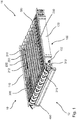
- Fig. 1 shows a schematic, three-dimensional view of an exemplary embodiment of a separation device.
- the separation device 10 extends from a first end 12 to a second end 14.
- the separation device 10 comprises a base frame 100, in which a drain element 200 is inserted.
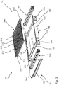
- the base frame 100 is formed by a first side member 110, a second side member 120 and an in Fig. 2 drain crossmember 130 shown and a support crossmember 132.
- the drain crossmember 130 and the support crossmember 132 are arranged essentially in parallel.
- the longitudinal beams 110, 120 are also arranged essentially parallel to one another.
- the longitudinal beams 110, 120 and the cross beams 130, 132 are arranged at right angles to one another.
- the drain element is in the base frame 100 formed by the first longitudinal beam 110, second longitudinal beam 120, the discharge cross beam 130 and the support cross beam 132 200 used.
- the drain element 200 comprises a plurality of drainage channels 210, the plurality of drainage channels being connected to one another by a first support beam 220 and a second support beam 222. Representative of the majority of drainage channels, the structure of drainage channel 210 is explained here by way of example.
- the gutter 210 is surrounded by a first shoulder 232 and a second shoulder 233.
- Each of the drainage channels extends from a first side of the drainage element, which faces the first end 12 of the separation device 10, to a second side, which faces the second end 14 of the separation device 10.
- the drainage channels 210 are designed such that a liquid can flow in them.
- the drainage element 200 and the drainage channels 210 are designed such that a drainage direction 212 is defined when the drainage element 200 is properly arranged on the base frame 100. If the drain element is arranged correctly, the drain channels 210 have an inclination to the horizontal. As a result, a liquid flows in the direction of the drain direction 212 indicated by an arrow toward an outflow end 214.
- Through openings 124, 125, 126, 127 are arranged in a region adjacent to the respective ends of the longitudinal beams.
- the passage openings 124-127 are designed such that a first deflection unit 310 and a second deflection unit 320 can be arranged on or in these. It is particularly preferred that the discharge cross member 130 and the support cross member 132 are arranged on the inside of the deflection units 310, 320.
- the deflection units 310, 320 are arranged and designed in such a way that they can guide an endless belt 300. That in the Fig. 1 Endless belt 300 shown broken is liquid-permeable.
- the endless belt 300 encloses the top and the bottom as well as the front sides of the separation device 10.
- the drain cross member 130 and the support cross member 132 have an upwardly open profile.
- the support beams 220, 222 of the drain element 200 have a profile corresponding to the profile of the drain cross member 130 and support cross member 132 which is open at the top.
- the support beams 220, 222 can be inserted into the profiles of the drain cross beam 130 and the support cross beam 132 which are open at the top.
- the support cross member 132 forms a fixed bearing in the direction from the first end 12 to the second end 14.
- the drain cross member 130 forms in the aforementioned direction Floating bearing.
- the drain cross member 130 has, in addition to the support for the first support beam 220, a lower drain cross channel 131.
- the drain channel 131 can also be arranged as a separate element on the drain cross member 130.
- the drain channel 131 can also be arranged as a separate element on the drain element 200 and / or on the base frame 100.
- a liquid located on the drain element 200 flows through the inclination of the drain element 200 in the drain direction 212.
- the arrangement of the drain element 200, the drain direction 212 resulting from the inclination and the arrangement of the drain cross channel 131 show that the liquid flows from the drain element 200 into the drain cross channel 131.
- the drainage channel 131 is connected to a drain opening 122 in the first side member.
- a liquid flowing through the endless belt 300 can be absorbed in the drain element 200 by the drain channels 210.
- the liquid flows through the resulting incline in the drain direction 212 into the drain cross channel 131.
- the drain cross channel 131 preferably also has an incline in the direction of the drain opening 122. This allows a liquid to flow from the endless belt 300 to a liquid collection station located outside the separation device.
- a manure scraper 400 is also arranged.
- the manure scraper 400 is intended to scrape a manure on the endless belt 300 when the endless belt is moved. By wiping the faeces should be placed in a defined position under the separation device 10. It is particularly preferred that the manure scraper 400 is configured or controlled such that the manure is not completely removed from the endless belt 300, but a part of the manure remains on it. In particular, it is preferred that this is implemented using a control method.
- the separation device 10 of animals, in particular pigs is identified and noted in the barn as a waste area. As a result, the animals, particularly pigs, seek to separate the separator 10 and keep the rest of the stall substantially clean.
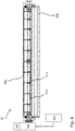
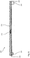
- the Fig. 4 shows a schematic, two-dimensional front view of the separation device 10 Fig. 1 .
- the first deflection unit 310 has a plurality of deflection disks 314.
- the deflection disks 314 are designed such that they can set the endless belt 300 in motion.
- the deflection disks 314 have a type of gear structure with which they can form a positive and / or non-positive connection with the endless belt 300.
- the separation device 10 comprises a drive 330.
- the drive 330 is coupled to the first deflection unit 310 and drives it in rotation.
- the drive 330 is coupled to a control device 340, which is arranged and designed to control the drive 330.
- control device 340 controls the drive 330 on a cycle basis.
- the drive 330 can be actuated, for example, at predefined time intervals and set the endless belt 300 in motion.
- control device 340 can also control the drive 330 according to a daily schedule, preferably taking the rest times of the animals into account.
- control device 340 can be designed to control the drive 330 in a sensor-based manner.
- the separation device preferably comprises at least one sensor 342.
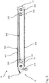
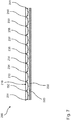
- the drain element 200 In the 5 - 7 Detailed views of the drain element 200 are shown. Especially in the Fig. 5 and 7 the construction of the drainage element is shown with a plurality of drainage channels, with one drainage channel being provided with the reference number 210 representative of all others, the drainage channel 210 extending between two shoulders 232, 233. The shoulders 232-240 and the shoulder shoulders 231, 241 thus form the lateral boundaries of the drainage channels.
- the drain element 200 extends from a blocking side 204 to a drain side 202.
- the drain channels 210 are blocked by a rear wall. This means that a liquid standing in the drainage channel cannot run off at the blocking side 204 at least up to a defined filling level.
- the drain ends 214 are arranged on the outlet side 202.
- the drainage side 202 is distinguished in particular with respect to the drainage channels by the fact that a liquid located in the drainage channels can drain off on the drainage side 202 essentially without problems.
- the first support beam 220 has a smaller extent in the vertical direction than the second support beam 222. Since the discharge cross beam 130 and the support cross beam 132 are arranged at the same height in the vertical direction on the longitudinal beams 110, 120, the differently long support beams 220, 222 an inclination of the drain element 200 relative to the base frame 100.
- the base frame 100 is set up essentially horizontally by feet, not shown, so that the drain element 200 has an incline as a result.
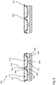
- Fig. 8 shows schematic, two-dimensional detailed views of gutters of the in Fig. 5 shown drain element.
- the exemplary structure of a gutter is explained using the gutter 210 as an example.
- the drainage channel 210 has a channel base 250.
- the channel bottom 250 is the deepest point of the drain channel 210 in the vertical direction.
- a first channel bottom wing 252 and a second channel bottom wing 254 extend from the channel bottom 250 away from the channel bottom 250.
- the channel bottom wings 252, 254 have an incline.
- a channel side wall 256, 258 is arranged at the outer ends of the channel bottom wings 252, 254.
- a channel bottom wing forms a leg of the drain channel with a channel side wall.
- the drainage channel 210 is made of a metal, as a result of which the drainage channel 210 can be shaped well.
- the first shoulder 232 is formed by the sheet of the gutter 210 and the sheet of the second gutter 211.
- the side walls 256 and 264 abut one another.
- the side wall 256 has a greater extension than the side wall 264.
- the extension which is larger at this point and which goes beyond that of the usual extension is referred to as the edge section 262.
- the edge section is kinked from the side wall 256 at the kink 260.
- the drain element 200 can be arranged in addition to the support beams 220, 222 on the base frame 100, in particular on the longitudinal beams 110, 120.
- Fig. 9 shows a schematic, three-dimensional view of an animal stable with a plurality of in Fig. 1 Separation devices 520 shown.
- the animal stall 500 comprises a control aisle 502 which is arranged in the middle in the longitudinal direction.
- a plurality of animal holding bays 510 are arranged on both sides along the inspection passage 502.
- the animal holding bays 510 each extend from the inspection aisle 502 to an outer wall 506, 508 of the animal stall 500.
- the animal holding bays 510 are in each case a separation device 520 is arranged.
- the separation device 520 is adjacent to the inspection passage 502.
- the separation device 520 extends over the entire side of the animal holding bay 510, which extends parallel to the inspection passage 502.
- the animal holding bay 510 is delimited from the inspection aisle 502 by a boundary wall 512.
- a disposal gap 514 is located between the boundary wall 512 and the separation device 520.
- a manure located on the endless belt of the separation device 520 can be disposed of by conveying it in the direction of the inspection passage 502 through the disposal gap 514.
- the manure is conveyed into the disposal passage 504 in particular through the disposal gap 514.
- Suitable devices can be arranged within the disposal passage 504 in order to dispose of the faeces from here.
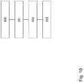
- Fig. 10 shows a schematic flow diagram of an exemplary embodiment of the method for separating faeces and urine in an animal house.
- a movable and liquid-permeable floor is provided in a first step 600.
- a floor can be designed, for example, as an endless belt and preferably as a modular belt.
- the liquid released by animals on the floor, in particular urine, is collected in drainage channels in step 601.
- the liquid passes through the floor and is collected under the floor in the gutters.
- the floor rests on the gutters.
- step 602 the liquid is discharged in the longitudinal direction of the drainage channels.
- step 603 the liquid is discharged in the transverse direction after removal in the longitudinal direction.
- the liquid can flow off at a drain end of the drainage channels into a transverse channel which is arranged orthogonally to the drainage channels.
- the method may further comprise the step of collecting faeces on the movable floor.
- the separation device has the advantage that an autonomous separation device for animal stalls is provided which separates the liquid and solid excrement from animals, in particular pigs.
- the present separation device offers the advantage that an endless belt can be used, which particularly corresponds to animal welfare and moreover has an optimal permeability for liquid excrement. This is achieved in particular in that the endless belt 300 itself does not have to bear the weight of an animal. This in turn results from the fact that the endless belt rests on the shoulders of the drain element 200. The shoulders form an inner support for the endless belt.
Landscapes
- Life Sciences & Earth Sciences (AREA)
- Environmental Sciences (AREA)
- Zoology (AREA)
- Animal Husbandry (AREA)
- Biodiversity & Conservation Biology (AREA)
- Chemical & Material Sciences (AREA)
- Chemical Kinetics & Catalysis (AREA)
- Housing For Livestock And Birds (AREA)
- Processing Of Solid Wastes (AREA)
Applications Claiming Priority (1)
| Application Number | Priority Date | Filing Date | Title |
|---|---|---|---|
| LU100969 | 2018-10-22 |
Publications (2)
| Publication Number | Publication Date |
|---|---|
| EP3643163A2 true EP3643163A2 (fr) | 2020-04-29 |
| EP3643163A3 EP3643163A3 (fr) | 2020-07-29 |
Family
ID=64959390
Family Applications (1)
| Application Number | Title | Priority Date | Filing Date |
|---|---|---|---|
| EP19204251.3A Pending EP3643163A3 (fr) | 2018-10-22 | 2019-10-21 | Dispositif de séparation permettant la réduction des émissions dans les stalles et stalle d'animaux |
Country Status (4)
| Country | Link |
|---|---|
| US (1) | US11696564B2 (fr) |
| EP (1) | EP3643163A3 (fr) |
| CN (1) | CN111068390A (fr) |
| MX (1) | MX2019012441A (fr) |
Cited By (1)
| Publication number | Priority date | Publication date | Assignee | Title |
|---|---|---|---|---|
| CN111631142A (zh) * | 2020-06-13 | 2020-09-08 | 徐州蔬客达农业科技有限公司 | 一种猪养殖用水泡粪养殖舍 |
Families Citing this family (3)
| Publication number | Priority date | Publication date | Assignee | Title |
|---|---|---|---|---|
| JP7595893B2 (ja) * | 2021-03-04 | 2024-12-09 | 株式会社ジェイテクト | 飼育装置 |
| CN113080072A (zh) * | 2021-04-08 | 2021-07-09 | 张掖市鑫山湖农牧发展有限公司 | 一种牛羊养殖用能够减少污染的粪便回收再利用装置及其使用方法 |
| CN114747497B (zh) * | 2021-09-29 | 2023-10-31 | 陕西顺鑫种猪选育有限公司 | 一种可控温方便排便的猪舍保育床 |
Citations (13)
| Publication number | Priority date | Publication date | Assignee | Title |
|---|---|---|---|---|
| US1090131A (en) | 1912-06-24 | 1914-03-17 | John P Bowditch | Cow-barn. |
| US1159129A (en) | 1914-12-07 | 1915-11-02 | Lars Tellefson | Conveyer mechanism. |
| US1187814A (en) * | 1915-08-09 | 1916-06-20 | Clifton J Carter | Manure-conveyer. |
| US3274973A (en) | 1964-06-09 | 1966-09-27 | Louis S Woods | Confinement feed method and apparatus therefor |
| WO2002043472A1 (fr) | 2000-11-30 | 2002-06-06 | Tommy Lindvall | Logement pour animaux comprenant des moyens de detection |
| EP1377158A1 (fr) | 2001-03-12 | 2004-01-07 | Tommy Lindvall | Dispositif et procede pour le logement des animaux |
| WO2007016758A1 (fr) | 2005-08-11 | 2007-02-15 | Atd Waste Systems Inc. | Dispositif de collecte des déchets permettant de séparer les déchets liquides des déchets solides |
| EP1678059B9 (fr) | 2003-10-16 | 2007-10-24 | Tommy Lindvall | Dispositif d'entrainement a friction pour un convoyeur et procede d'entrainement |
| WO2013048333A1 (fr) | 2011-09-29 | 2013-04-04 | Tommy Lindvall | Installation pour logement d'animaux |
| DE102016000308A1 (de) | 2015-08-24 | 2017-03-02 | Ralf Remmert | Stall, insbesondere für die Haltung von Schweinen. |
| WO2017121864A1 (fr) | 2016-01-13 | 2017-07-20 | Ralf Remmert | Stalle, en particulier pour contenir des porcs |
| WO2017202470A1 (fr) * | 2016-05-26 | 2017-11-30 | Lorraine Costello | Installation d'élevage de bétail |
| DE102016013326A1 (de) | 2016-11-09 | 2018-05-09 | Ralf Remmert | Stall, insbesondere für die Haltung von Schweinen. |
Family Cites Families (10)
| Publication number | Priority date | Publication date | Assignee | Title |
|---|---|---|---|---|
| US502004A (en) * | 1893-07-25 | log-an | ||
| US1177695A (en) * | 1915-03-27 | 1916-04-04 | John I Gable | Stable-cleaning device. |
| US3119374A (en) * | 1963-03-04 | 1964-01-28 | Ladner Gerard | Revolving sanitary floor for horse stalls |
| US3611472A (en) * | 1969-02-04 | 1971-10-12 | Lee L Kayser | Self-cleaning floor |
| US4402282A (en) * | 1980-06-06 | 1983-09-06 | Forrest Redi-Mix Co. | Method of constructing a system of gutters for a swine building |
| US4353328A (en) * | 1980-06-06 | 1982-10-12 | Forrest Redi-Mix Co. | Method and apparatus for constructing a system of gutters for a swine building |
| NL9300207A (nl) * | 1993-02-02 | 1994-09-01 | Johannes Martinus Willibrordus | Roostervloer voor een veestal. |
| US5817241A (en) * | 1997-08-11 | 1998-10-06 | Brayboy; Lois F. | Method for separating hog sewage into liquid and solid components |
| US20170208771A1 (en) * | 2016-01-21 | 2017-07-27 | Timothy H Craig | Method for Separating Swine Waste |
| PL3598892T3 (pl) | 2018-07-25 | 2025-05-19 | Big Dutchman International Gmbh | Sposób wytwarzania maty słomianej, mata słomiana i ściółkowy budynek inwentarski |
-
2019
- 2019-10-17 MX MX2019012441A patent/MX2019012441A/es unknown
- 2019-10-18 CN CN201910993813.8A patent/CN111068390A/zh active Pending
- 2019-10-21 US US16/658,712 patent/US11696564B2/en active Active
- 2019-10-21 EP EP19204251.3A patent/EP3643163A3/fr active Pending
Patent Citations (13)
| Publication number | Priority date | Publication date | Assignee | Title |
|---|---|---|---|---|
| US1090131A (en) | 1912-06-24 | 1914-03-17 | John P Bowditch | Cow-barn. |
| US1159129A (en) | 1914-12-07 | 1915-11-02 | Lars Tellefson | Conveyer mechanism. |
| US1187814A (en) * | 1915-08-09 | 1916-06-20 | Clifton J Carter | Manure-conveyer. |
| US3274973A (en) | 1964-06-09 | 1966-09-27 | Louis S Woods | Confinement feed method and apparatus therefor |
| WO2002043472A1 (fr) | 2000-11-30 | 2002-06-06 | Tommy Lindvall | Logement pour animaux comprenant des moyens de detection |
| EP1377158A1 (fr) | 2001-03-12 | 2004-01-07 | Tommy Lindvall | Dispositif et procede pour le logement des animaux |
| EP1678059B9 (fr) | 2003-10-16 | 2007-10-24 | Tommy Lindvall | Dispositif d'entrainement a friction pour un convoyeur et procede d'entrainement |
| WO2007016758A1 (fr) | 2005-08-11 | 2007-02-15 | Atd Waste Systems Inc. | Dispositif de collecte des déchets permettant de séparer les déchets liquides des déchets solides |
| WO2013048333A1 (fr) | 2011-09-29 | 2013-04-04 | Tommy Lindvall | Installation pour logement d'animaux |
| DE102016000308A1 (de) | 2015-08-24 | 2017-03-02 | Ralf Remmert | Stall, insbesondere für die Haltung von Schweinen. |
| WO2017121864A1 (fr) | 2016-01-13 | 2017-07-20 | Ralf Remmert | Stalle, en particulier pour contenir des porcs |
| WO2017202470A1 (fr) * | 2016-05-26 | 2017-11-30 | Lorraine Costello | Installation d'élevage de bétail |
| DE102016013326A1 (de) | 2016-11-09 | 2018-05-09 | Ralf Remmert | Stall, insbesondere für die Haltung von Schweinen. |
Cited By (2)
| Publication number | Priority date | Publication date | Assignee | Title |
|---|---|---|---|---|
| CN111631142A (zh) * | 2020-06-13 | 2020-09-08 | 徐州蔬客达农业科技有限公司 | 一种猪养殖用水泡粪养殖舍 |
| CN111631142B (zh) * | 2020-06-13 | 2022-05-10 | 徐州蔬客达农业科技有限公司 | 一种猪养殖用水泡粪养殖舍 |
Also Published As
| Publication number | Publication date |
|---|---|
| MX2019012441A (es) | 2020-07-14 |
| US20200120893A1 (en) | 2020-04-23 |
| CN111068390A (zh) | 2020-04-28 |
| BR102019021663A2 (pt) | 2020-06-23 |
| US11696564B2 (en) | 2023-07-11 |
| EP3643163A3 (fr) | 2020-07-29 |
| US20210051915A9 (en) | 2021-02-25 |
Similar Documents
| Publication | Publication Date | Title |
|---|---|---|
| EP3402322B1 (fr) | Stalle, en particulier pour contenir des porcs | |
| DE602004012455T2 (de) | Haustiertoilette | |
| DE102005063310B4 (de) | Kotfördereinrichtung | |
| DE202017007447U1 (de) | Stall, insbesondere für die Haltung von Schweinen | |
| AT521304B1 (de) | Stall für die Schweinemast | |
| AT519396A1 (de) | Bodenkonstruktion für einen Pferdeeinstellplatz | |
| EP3241433A1 (fr) | Système de maintien de volaille et procédé de transport d'oeufs dans un système de maintien de volaille | |
| DE102016013326A1 (de) | Stall, insbesondere für die Haltung von Schweinen. | |
| DE60100126T2 (de) | Stall zum Trennen von Dung | |
| DE3713611C2 (de) | Einrichtung für die Haltung von Kleintieren, insbesondere Mastgeflügel, wie Hähnchen | |
| DE202018106036U1 (de) | Trennungsvorrichtung zur Emissionsreduktion in Ställen und Tierstall | |
| DE10142548B4 (de) | Stall für die Haltung von Säugetieren, insbesondere für die Schweinemast | |
| DE10027480B4 (de) | Boden für Tierställe, insbesondere Pferdeställe | |
| DE3528604A1 (de) | Entmistungsanlage fuer kleintierfarmen | |
| EP1673972A1 (fr) | Système d'éléments préfabriqués en béton pour un sol d'étable, sol d'étable comprenant lesdits éléments et procédé pour sa fabrication | |
| WO1997025857A1 (fr) | Dispositif d'evacuation du fumier pour etable a canaux de collecte du fumier evacues mecaniquement | |
| EP3020271B1 (fr) | Installation d'etable | |
| DE102023125497B3 (de) | Vorrichtung und Verfahren zum Aufbringen von Streumaterial bei der Tierhaltung | |
| DE19953236C1 (de) | Futterdosiervorrichtung für rieselfähiges Tierfutter | |
| AT505895B1 (de) | Entmistungssystem zur beseitigung von stallmist | |
| DE2703968A1 (de) | Einbau fuer einen stall zur haltung von insbesondere mast-gefluegel | |
| DE202004000471U1 (de) | Einstreuvorrichtung für Ställe | |
| EP0027981B1 (fr) | Installation de pondoirs pour fermes avicoles | |
| DE202024103419U1 (de) | Anordnung zum Abführen von Jauche in einem automatisierten Stall | |
| EP4691227A1 (fr) | Dispositif de transport de fumier, notamment pour l'utilisation dans la production d'ouaux en grange ou la production de poulets de chair |
Legal Events
| Date | Code | Title | Description |
|---|---|---|---|
| PUAI | Public reference made under article 153(3) epc to a published international application that has entered the european phase |
Free format text: ORIGINAL CODE: 0009012 |
|
| STAA | Information on the status of an ep patent application or granted ep patent |
Free format text: STATUS: THE APPLICATION HAS BEEN PUBLISHED |
|
| AK | Designated contracting states |
Kind code of ref document: A2 Designated state(s): AL AT BE BG CH CY CZ DE DK EE ES FI FR GB GR HR HU IE IS IT LI LT LU LV MC MK MT NL NO PL PT RO RS SE SI SK SM TR |
|
| AX | Request for extension of the european patent |
Extension state: BA ME |
|
| PUAL | Search report despatched |
Free format text: ORIGINAL CODE: 0009013 |
|
| AK | Designated contracting states |
Kind code of ref document: A3 Designated state(s): AL AT BE BG CH CY CZ DE DK EE ES FI FR GB GR HR HU IE IS IT LI LT LU LV MC MK MT NL NO PL PT RO RS SE SI SK SM TR |
|
| AX | Request for extension of the european patent |
Extension state: BA ME |
|
| RIC1 | Information provided on ipc code assigned before grant |
Ipc: A01K 1/02 20060101ALI20200622BHEP Ipc: A01K 1/01 20060101AFI20200622BHEP |
|
| STAA | Information on the status of an ep patent application or granted ep patent |
Free format text: STATUS: REQUEST FOR EXAMINATION WAS MADE |
|
| 17P | Request for examination filed |
Effective date: 20210129 |
|
| RBV | Designated contracting states (corrected) |
Designated state(s): AL AT BE BG CH CY CZ DE DK EE ES FI FR GB GR HR HU IE IS IT LI LT LU LV MC MK MT NL NO PL PT RO RS SE SI SK SM TR |
|
| STAA | Information on the status of an ep patent application or granted ep patent |
Free format text: STATUS: EXAMINATION IS IN PROGRESS |
|
| 17Q | First examination report despatched |
Effective date: 20250417 |