EP3643203A1 - Chaise - Google Patents
Chaise Download PDFInfo
- Publication number
- EP3643203A1 EP3643203A1 EP17915037.0A EP17915037A EP3643203A1 EP 3643203 A1 EP3643203 A1 EP 3643203A1 EP 17915037 A EP17915037 A EP 17915037A EP 3643203 A1 EP3643203 A1 EP 3643203A1
- Authority
- EP
- European Patent Office
- Prior art keywords
- seat
- guide
- flange part
- chair
- guide hole
- Prior art date
- Legal status (The legal status is an assumption and is not a legal conclusion. Google has not performed a legal analysis and makes no representation as to the accuracy of the status listed.)
- Granted
Links
Images


Classifications
-
- A—HUMAN NECESSITIES
- A47—FURNITURE; DOMESTIC ARTICLES OR APPLIANCES; COFFEE MILLS; SPICE MILLS; SUCTION CLEANERS IN GENERAL
- A47C—CHAIRS; SOFAS; BEDS
- A47C7/00—Parts, details, or accessories of chairs or stools
- A47C7/02—Seat parts
- A47C7/14—Seat parts of adjustable shape; elastically mounted ; adaptable to a user contour or ergonomic seating positions
-
- A—HUMAN NECESSITIES
- A47—FURNITURE; DOMESTIC ARTICLES OR APPLIANCES; COFFEE MILLS; SPICE MILLS; SUCTION CLEANERS IN GENERAL
- A47C—CHAIRS; SOFAS; BEDS
- A47C3/00—Chairs characterised by structural features; Chairs or stools with rotatable or vertically-adjustable seats
- A47C3/02—Rocking chairs
- A47C3/025—Rocking chairs with seat, or seat and back-rest unit, elastically mounted in a rigid frame
- A47C3/0255—Rocking chairs with seat, or seat and back-rest unit, elastically mounted in a rigid frame pivotally mounted in the base frame, e.g. swings
-
- A—HUMAN NECESSITIES
- A47—FURNITURE; DOMESTIC ARTICLES OR APPLIANCES; COFFEE MILLS; SPICE MILLS; SUCTION CLEANERS IN GENERAL
- A47C—CHAIRS; SOFAS; BEDS
- A47C3/00—Chairs characterised by structural features; Chairs or stools with rotatable or vertically-adjustable seats
- A47C3/02—Rocking chairs
- A47C3/025—Rocking chairs with seat, or seat and back-rest unit, elastically mounted in a rigid frame
- A47C3/026—Rocking chairs with seat, or seat and back-rest unit, elastically mounted in a rigid frame with a central column, e.g. rocking office chairs; Tilting chairs
-
- A—HUMAN NECESSITIES
- A47—FURNITURE; DOMESTIC ARTICLES OR APPLIANCES; COFFEE MILLS; SPICE MILLS; SUCTION CLEANERS IN GENERAL
- A47C—CHAIRS; SOFAS; BEDS
- A47C7/00—Parts, details, or accessories of chairs or stools
- A47C7/002—Chair or stool bases
- A47C7/006—Chair or stool bases with castors
-
- A—HUMAN NECESSITIES
- A47—FURNITURE; DOMESTIC ARTICLES OR APPLIANCES; COFFEE MILLS; SPICE MILLS; SUCTION CLEANERS IN GENERAL
- A47C—CHAIRS; SOFAS; BEDS
- A47C7/00—Parts, details, or accessories of chairs or stools
- A47C7/36—Supports for the head or the back
- A47C7/40—Supports for the head or the back for the back
- A47C7/44—Supports for the head or the back for the back with elastically-mounted frame
Definitions
- the present invention relates to a chair suitably used in an office and the like.
- Some of office chairs are provided with movable part in supporting portions such as a seat and a back in order to appropriately support a seated person.
- Patent Documents 1 and 2 Such office chairs are shown in Patent Documents 1 and 2, and realize a desired operation by moving a follower along a guide surface.
- the chairs in these documents includes a first shaft and a second shaft, the first shaft provided at the rear part of the seat is movably engaged with a first guide groove provided at the support base part side, the second shaft provided at the front part of the seat is movably engaged with a second guide groove provided at the support base part side of the office chair, and thereby associates forward tilt and reward tilt movements of the back and seat with the front-rear movements of the back and seat.
- these chairs are configured that the guide groove is formed by opening a hole in a guide plate which forms a vertical wall. Accordingly, in order to secure require strength, there is a subject that the guide plate becomes thicker.
- the chair described in the Patent Documents 2 is configured so that a resin-made guide plate having a guide groove with a required width is attached to the outer side of the vertical wall, and a hole larger than the guide groove is provided in the vertical wall, and the shaft is inserted through the guide groove to be supported by the guide groove of the guide plate.
- Patent Document 2 in order to secure the pressure receiving area, it is sufficient to thicken only the resin member.
- a movable part is a part that moves under the load applied by seated person.
- the softer guide groove may be deformed or scraped, leading to rattling or damage to the movable portion.
- this may also be a causes of cost increase.
- the cylindrical part in which the shaft is freely movable fitted is formed by burring processing on at a member made of a metal plate. And a cylindrical part increases height of protrusion without damaging in a burring process, and the support strength of the shaft can be improved.
- the length of the long hole is made considerably larger than the movement stroke of the shaft, and the projecting dimension is made smaller at the both ends of the long hole in the cylindrical part. And the projecting dimension is made larger in the moving range of the shaft. Since the cylindrical part has small projecting dimensions at both ends of the long hole, the cylindrical part is not broken in the burring processing.
- the stroke regulation of the shaft is performed at a portion other than the long hole or by thickening the thickness of both left and right ends part of the bush.
- a shaft twists with respect to a left and right long holes, and it will be in a state which is hard to move.
- the shaft may be in contact with the lower edge of one of the left and right long holes and the other at the upper edge.
- the shaft receive such a force that one of the left and right moves forward or rotates forward and the other moves backward or rotates backward.
- the present invention focuses on such problems and an object thereof is to realize a chair, and the chair can appropriately support a chair whose seat moves the front, rear, right, or left with a simple structure.
- the present invention adopts the following means to achieve such object.
- a movable portion that moves in the state of receiving a load applied by seated person is configured to be operable to the front, rear, right, or left with respect to the support base portion
- a flange part is provided on a vertical surface on the plate member of the movable portion or support base portion, and the flange part has a guide surface extending lateral direction and moving the rolling body in the longitudinal direction, and a lateral dimension of the guide surface is greater than a thickness of the plate member.
- the flange part and the portion of the plate member part forming the vertical surface around the flange part are integrally formed of metal; the flange part has a shape formed around the entire circumference of a guide hole opened in the vertical surface, the rolling body is provided so as to be roll independently on the left and right along the guide surface.
- the pressure receiving area of the guide hole in contact with the rolling body is increased, and load distribution can be achieved, resulting in improved durability. Furthermore, by providing the flange part integrally with the plate member of the movable portion with metal, high strength can be secured, and a rib effect by the flange part can also be expected. At the result, the rolling body can be reliably supported and easily rolled without thickening the plate member. Further, the chair that moves while sitting is particularly applied high load, so the present invention is particularly effective. Furthermore, when the movable part moves in the front, rear, right, or left in the state of receiving a load applied by seated person, even if the shaft center positions of the left and right rolling bodies are shifted the guide surface, the operation can be secured.
- one of the rolling body can be in contact with the lower edge of the guide surface and the other with the upper edge of the guide surface, and the rolling body can perform an operation in which one of left and right moves rolling body forward or rotates forward and the other moves backward or rotates backward, so that it is possible to appropriately respond to right and left unbalanced external force or movement.
- the lateral dimension of the guide surface be substantially uniform over the entire circumference.
- the flange part is formed by plastic deformation processing of the plate member around the guide hole.
- the flange part is formed to extend from the guide hole outward the left-right direction of the chair.
- an end part of the guide hole has a shockless shape that lefts the center of gravity of the movable portion in order to mitigate a shock due to a collision with the rolling body.
- the rolling body is configured of a metal bearing.
- the shortest dimension from the both ends of the guide hole to the edge of the plate member is set 15 mm or more.
- the present invention is extremely useful when applying to a chair in which the movable portion is supported by the support portion at two locations on the front and rear, any one of the front and rear support structures is configured by the rolling part and the guide surface, and the other support structure are configured by a different structure.
- the new chair whose seat moves the front, rear, right, or left and supported appropriately with a simple structure can be provided.
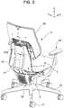
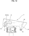
- this chair is an office chair configured by erecting a leg supporting post 13 incorporating a lifting/lowering mechanism therein, in a central part of a leg vane 12 supported by a caster 11, and attaching a support base part 2 rotatably at an upper end side of the leg supporting post 13.
- a seat 5 being a movable part is supported via a front-rear swing part 3 as a one-direction operating part (movable part) operable any one of a front-rear direction (X-direction in the drawings) and a right-left direction (Y-direction in the drawings) being two directions crossing each other, and a left-right swing part 4 being an other-direction operating part (support part) operable in the other of the front-rear direction and the left-right direction and the seat 5 can swing in the front-rear direction and the right-left direction with respect to the support base part 2.
- a front-rear swing part 3 as a one-direction operating part (movable part) operable any one of a front-rear direction (X-direction in the drawings) and a right-left direction (Y-direction in the drawings) being two directions crossing each other
- a left-right swing part 4 being an other-direction operating part (support part) operable in the other of the front-rear direction and the left-right
- the front-rear swing part 3 is provided between the seat 5 and the support base part 2 configured to support the seat 5, and the left-right swing part 4 is provided between the front-rear swing part 3 and the support base part 2. Behind the seat 5, a back 6 is arranged.
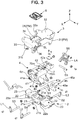
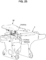
- the support base part 2 functions as a structured body for receiving the load applied by seated person, and in the support base part 2, a left-right pair of arm attachment parts 23 is integrally formed with the support base part 2 via a bearing base part 22 on both left and right sides of a support base main body 21 including a through hole 21a along an up-down direction into which an upper end of the supporting post 13 is inserted.
- a shaft swing damper 21b is attached to the hole 21a opening on the surface of the support base main body 21 in the front-rear direction and upper ends of left-right swing links L1, L2 are attached to holes 22a opening on the front and rear surfaces of the bearing base part 22, via swing shafts S1, S2.
- the left-right swing part 4 includes a pair of plate-shaped link bases 41 disposed separated from each other in the front-rear direction to perform a swinging operation in the left-right direction with respect to the support base part 2, and a left-right swing main body 42 configured to connect the pair of link bases 41, 41.
- holes 41a, 41a are opened and the lower ends of the left-right swing links L1, L2 are attached via swing shafts S3, S4.
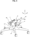
- FIG. 4 illustrates a state where the links L1, L2 are attached via the swing shafts S1 to S4. As illustrated in FIGS.
- the left-right swing main body 42 is provided with a unit attached hole 42a penetrating in the up-down direction, and a later-described left-right lock unit 7 is attached to the unit attached hole 42a. That is, the left-right swing main body 42 is disposed in a suspended state to be swingable to the left and right with respect to the support base part 2 via the left-right swing links L1, L2, and the left-right swing links L1, L2 are attached so that the distance between the lower ends is smaller than the distance between the upper ends, as illustrated in FIG. 4 and the like.
- a window 41c is opened at the center of the link base 41, a rolling damper 44 is positioned in the window 41c, and a swing range of the left-right swing part 4 is restricted to a range where the rolling damper 44 can perform a relative movement within the window 41c.
- the front-rear swing part 3 includes a pair of plate-shaped rail plates 31, 31 disposed separated from each other in the left-right direction to perform a swinging operation in the front-rear direction with respect to the left-right swing part 4, and an upper connection plate 32 and a front connection plate 33 configured to connect the pair of rail plates 31, 31.
- a guide hole 34 is provided to penetrate the rail plates 31, a bearing 45a is engaged in the guide hole 34, and the bearing 45a is a rolling body 45 provided to be rollable independently to the left and right on a side surface at a front end side of the left-right swing main body 42.
- the reference sign 45z in the drawings indicates a spacer disposed on an inner surface side of the rail plate 31 and having a diameter larger than that of the bearing 45a.
- the rear end side of the rail plate 31 extends rearward and downward, a lower end of a link arm LA, being a swingable front-rear swing link, is attached via a swing shaft S5 to an extension end of the rail plate 31, and the upper end of the link arm LA is supported by the rear end of the left-right swing body 4 via a swing shaft S6. That is, the rear end of the front-rear swing part 3 is disposed in a suspended state to be swingable forward and rearward with respect to the left-right swing part 4 via the link arm LA.
- the guide hole 34 has a shape that is gently curved forward and downward from the rear end side toward the front end side, and at the rear end, there is provided a shockless part SL configured to mitigate a shock when the front-rear swing part 3 moves forward together with the seat 5.
- the upper connection plate 32 is provided with a unit attached hole 32a penetrating in the up-down direction, and a front-rear lock unit 8 described later based on FIG. 16 is attached to the unit attached hole 32a.
- Axles of the bearing 45a being the rolling body 45 in the example of the drawings are separated to the left and right. However, as long as the bearing 45a being the rolling body 45 is rollable independently to the left and right, the axle may be common.
- the bearing 45 performs a relative movement with respect to the rear end side of the guide hole 34 at the front end of the front-rear swing part 3, so that the front end side of the front-rear swing part 3 is guided to a lower position, and the link arm LA approaches a horizontal posture.
- an operation is performed where the rear end of the front-rear swing part 3 is lifted to a higher position. That is, the front-rear swing part 3 performs an inclining operation so that the moving tip side is also lower in the front-rear direction.
- a pitching damper 31c formed by bending a part of the rail plate 31 is provided, and when swinging rearward, the front-rear swing part 3 abuts against a front end lower part 4z (see FIG. 3 ) of the left-right swing part 4 in the vicinity of the swing end to mitigate the shock at the rearward movement end.
- a back frame 61 included in the back 6 is attached to a rear part of the upper connection plate 32 included in a front-rear swing body 3, and a seat outer shell 51 (see FIG. 15 ) included in the seat 5 is attached to the connection plate 32 from above.That is, when the back frame 61 configured to support a backrest 62 is erected integrally behind the seat 5 and the seat 5 swings in the front-rear and left-right directions with respect to the support base part 2, as indicated by X and Y in the drawing, the back frame 61 also moves together with the seat 5, but the backrest 62 according to the present embodiment operates separately from the back frame 61 and the seat 5, as described later.
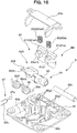
- a front-rear stopper mechanism 8M utilizing the front-rear lock unit 8 illustrated in FIGS. 16 to 18 is provided to suppress a swinging of the seat 5 in the front-rear direction relative to the support base part 2 at a predetermined position through an operation of an operating member 152 illustrated in FIG. 15 .
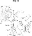
- a left-right stopper mechanism 7M utilizing the left-right lock unit 7 illustrated in FIGS. 19 and 20 is provided to suppress a swinging of the seat 5 in the left-right direction relative to the support base part 2 at a position determined in advance through an operation of an operating member 151 (being an operating member common with the operating member 152 in practice) illustrated in FIG. 15 .
- the left-right swing part 4 is supported by the support base part 2 and the front-rear swing part 3 is supported by the left-right swing part 4 so that a layered structure is formed in which the left-right stopper mechanism 7M is provided between the support base part 2 and the left-right swing part 4, and the front-rear stopper mechanism 8M is provided between the left-right swing part 4 and the front-rear swing part 3.
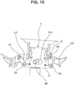
- the left-right stopper mechanism 7M is configured to switch between allowing and suppressing the swinging of the seat 5 in the left-right direction, by engaging or disengaging an engaging part 71 and an engaged part 72 illustrated in FIG. 21(a) when the operating member 151 illustrated in FIG. 15 is operated.
- the left-right stopper mechanism 7M includes an engagement pin 71a being the engaging part 71 provided at the side of the left-right swing part 4 and a groove 72a being the engaged part 72 provided on a sliding surface 20, the engaged part 72 relatively operating at the side of the support base part 2 being a position facing the engagement pin 71a.
- the engagement pin 71a is configured to be elastically biased toward the sliding surface 20, and to be fitted in the groove 72a at a predetermined position.
- the groove 72a has a rectangular shape in plan view and is provided at a center reference position in the left-right direction of the support base part 2 exposed upward via an opening 4t of the left-right swing part 4, and the engagement pin 71a illustrated in FIG. 20 is engaged to and disengaged from the groove 72a.
- a coil spring 73a being an elastic member 73 functions to bias the engagement pin 71a in a direction where the engagement pin 71a protrudes toward the sliding surface 20.
- the left-right stopper mechanism 7M includes a conversion mechanism 74 illustrated in FIGS.
- the casing 70 has a halved structure, and the engagement pin 71a is disposed to be liftable and lowerable in a state where a wide part 71aw of the engagement pin 71a is guided by inner surfaces of side walls 70a, 70b of the casing 70 while a tip end part 71as being a part of the engagement pin 71a protrudes from a lower end of the casing 70.
- the conversion mechanism 74 includes the above-described coil spring 73a provided elastically in a compressed state between an upper end of the engagement pin 71a and an upper wall 70p of the casing 70, a stopper operation arm 75 rotatably supported via a horizontal shaft 70c between the side walls 70a, 70b of the casing 70 at a position adjacent to the engagement pin 71a, a torsion coil spring 76 rotatably attached together with the stopper operation arm 75, and a wire tube 77 including a spherical wire tip end 77a to be attached to the stopper operation arm 75 and a tube tip end 77b locked to the casing 70. As illustrated in FIG.
- the other end of the wire tube 77 is locked in the vicinity of an operation lever 151a being the operating member 151 provided in the seat 5 and a wire base end 77c drawn therefrom is connected to the operation lever 151a.
- a tip end 76b of the torsion coil spring 76 is engaged with a hole 71a1 provided on the engagement pin 71a.
- an attachment part 70m provided in the casing 70 is mounted on an upper surface of the swing main body part 42 and fixed by screwing.
- the left and right side walls 70a, 70b of the casing 70 are tightly accommodated between left and right side walls 42a1, 42a2 of the unit attached hole 42a and the engagement pin 71a is tightly guided in the casing 70 by the inner surfaces of the side walls 70a, 70b of the casing 70.
- the unit attached hole 42a of a left-right swing part 13 illustrated in FIG. 7 includes merely the left and right side walls 42a1, 42a2, a rear wall 42a3, and an inclined front wall 42a4 to form the lower opening 4t without a bottom wall.
- the engagement pin 71a is configured to hang directly from the lower opening 4t of the unit attached hole 42a without being guided by the bottom wall to abut against the sliding surface 20, to engage with the groove 72a. Parts in the front-rear direction of the engagement pin 71a are supported by front and rear guide walls formed in the casing 70.
- the groove 72a is formed between longitudinal ribs r1, r1 provided in the support base part 2, lateral ribs r2 are provided around the longitudinal ribs r1, r1, and upper surfaces of the longitudinal ribs r1 and the lateral ribs r2 form the sliding surface 20 on which the engagement pin 71a slides until engaging with the groove 72a.
- the wire tube 77 rotates the stopper operation arm 75 to compress the coil spring 73a while the engagement pin 71a is lifted upwards at a tip end 76b of the torsion coil spring 76.
- the tip end 76b of the torsion coil spring 76 rotates together with the stopper operation arm 75 by the repulsive force of the coil spring 73a, the engagement pin 71a is pressed downward, and when the engagement pin 71a engages with the groove 72a of the support base part 2, the locked state in the left-right direction is realized.
- the front-rear stopper mechanism 8M is configured to switch between allowing and suppressing the swinging of the seat 5 in the front-rear direction, by engaging or disengaging an engaging part 81 and an engaged part 82 illustrated in FIG. 21(b) when the operating member 152 illustrated in FIG. 15 is operated.
- a configuration is so that the front-rear stopper mechanism 8M includes an engagement pin 81a being the engaging part 81 provided at the side of the front-rear swing part 3 and a groove 82a being the engaged part 82 provided on a sliding surface 40, the engaged part 82 relatively operating at the side of the left-right swing part 4 being a position facing the engagement pin 81a.
- the engagement pin 81a is configured to be elastically biased toward the sliding surface 40, and to fit in the groove 82a at a predetermined position.
- the groove 82a is provided on an upper surface of the swing main body part 42 of the left-right swing part 4 at one or more predetermined locations (one location in the present embodiment) within a movable range of the engagement pin 81a when the engagement pin 81a of the front-rear swing part 3 mounted on the upper surface of the swing main body part 42 moves in the front-rear direction, and thus, the groove 82a has a shape extending in the left-right direction and an upper surface of a swing main body part 41 forms the sliding surface 40.
- a coil spring 83a being an elastic member 83 functions to bias the engagement pin 81a in a direction where the engagement pin 81a protrudes toward the sliding surface 40, a conversion mechanism 84 illustrated in FIGS. 16 and 17 is provided, the conversion mechanism 84 converting an operation of the operating member 152 into an operation in a direction in which the engagement pin 81a is separated from the sliding surface 40, and the conversion mechanism 84, the engagement pin 81a, and the coil spring 83a are integrally incorporated into a half-piece of the casing 80 to form with unitized
- the casing 80 has a flat saucer-shape opened upward, and thus, the engagement pin 81a is guided by a guide 80g1 in the casing 80, and is disposed to be liftable and lowerable with a part of the engagement pin 81a protruding from a lower end of the casing 80.
- the conversion mechanism 84 includes the above-described coil spring 83a provided elastically in a compressed state between an upper end of the engagement pin 81a and a cover 80a closing the upper opening of the casing 80, a stopper operation arm 85 rotatably supported by a horizontal shaft 80c disposed between side walls 80b, 80b of the casing 80 at a position adjacent to the engagement pin 81a, a torsion coil spring 86 rotatably attached together with the stopper operation arm 85, and a wire tube 87 having a spherical wire tip end 87a that is attached to the stopper operation arm 85 and a tube tip end 87b locked to the casing 80. As illustrated in FIG.
- the other end of the wire tube 87 is locked in the vicinity of an operation lever 152a being the operating member 152 provided in the seat 5 and a wire base end 87c drawn therefrom is connected to the operation lever 152a.
- a tip end 86a of the torsion coil spring 86 is at all times smoothly slidably engaged with a downward-facing surface 81a1 of the engagement pin 81a.
- a control mechanism 8X configured to automatically suppress a movement of the seat 5 in the front-rear direction at a predetermined position when the seated person leaves the seat, is provided along with the half-piece of a part 8 of the front-rear stopper mechanism 8M.
- a configuration is such that a weight-receiving part 50 (see FIG. 15 ), the height position of which changes due to a person sitting on a seat surface, is provided substantially at a center position of the seat 5, the change of the height position is mechanically transmitted to the control mechanism 8X illustrated in FIGS. 16 and 18 configured to control an operation of the front-rear swing part 3 being the movable part, and the control mechanism 8X changes the operation of the front-rear swing part 3, that is, the front-rear operation of the seat 5, between allowed and suppressed states.
- the control mechanism 8X changes the allowed/suppressed states of the operation of the front-rear swing part 3 when an engagement state of an engaging part 81X illustrated in FIG. 21(c) and provided in the front-rear swing part 3 being a movable part and an engaged part 82X provided in the left-right swing part 4 being a support part configured to support the front-rear swing part 3 changes due to the load applied by seated person, and returns, by the elastic member 83X, the state of the front-rear swing part 3 from an operation state where the operation of the front-rear swing part 3 is allowed to the original state where the operation of the front-rear swing part 3 is suppressed, if the load applied by seated person is removed.
- the chair is configured such that the engaged part 82X is a recess 82aX, and when the load applied by seated person is received in the state where the engaging part 81X is fitted into the recess 82aX, the fitted state is released, so that the engaging part 81X and the engaged part 82X are disengaged due to the load applied by seated person, and when the load applied by seated person is removed, the engaging part 81X and the engaged part 82X engage with each other by the elastic force to bring the front-rear swing part 3 into an operation-suppression state.
- the control mechanism 8X includes an engagement pin 81aX being the engaging part 81X, and a groove-shaped recess 82aX being an engaged part 82X provided on a sliding surface 40X relatively operating at a position facing the engagement pin 81X.
- the engagement pin 81aX is configured to be elastically biased toward the sliding surface 40X, and to fit in the groove-shaped recess 82aX at a predetermined position. Then, when the seat 5 detects received of the load applied by seated person in the central part, the control mechanism 8X illustrated in FIGS. 16 and 17 separates the engagement pin 81aX from the groove-shaped recess 82aX.
- a coil spring 83aX being an elastic member 83X functions to bias the engagement pin 81aX in a direction where the engagement pin 81aX protrudes toward the sliding surface 40X.
- the control mechanism 8X includes a conversion mechanism 84X configured to convert an operation of the weight-receiving part 50 due to a person sitting on the seat, into an operation in a direction where the engagement pin 81aX is separated from the sliding surface 40X, and the conversion mechanism 84X, the engagement pin 81aX, and the coil spring 83aX are integrally incorporated into an other-half part of the casing 80 illustrated in FIG. 16 , to form with unitized.
- the engagement pin 81aX is disposed to be l liftable and lowerable along front, rear, right, or left guides 80g2 of the casing 80, in a parallel relationship with the engagement pin 81 in the flat casing 80 configuring the front-rear stopper mechanism 8M.
- the conversion mechanism 84X includes the coil spring 83aX provided elastically in a compressed state between an upper end of the engagement pin 81aX and the cover 80a closing the upper opening of the casing 80, a safety operation arm 85X rotatably supported by the horizontal shaft 80c disposed between side walls 80b, 80b of the casing 80 at a position adjacent to the engagement pin 81aX, and a torsion coil spring 86X rotatably attached together with the safety operation arm 85X.
- the weight-receiver 50 is, as illustrated in FIG.
- a pressure-receiving plate 52a rotatably fitted and attached to the seat outer shell 51 included in the seat 5, and a convex part 52b provided below the pressure-receiving plate 52a is disposed at a position displaced from the center of rotation of the safety operation arm 85X, where the convex part 52b can press a pressed part 85xt illustrated in FIG. 16 .
- a tip end 86aX of the torsion coil spring 86X is at all times smoothly slidably engaged with a downward-facing surface of the engagement pin 81aX.
- the pressure-receiving plate 52a is biased in a direction away from the safety operation arm 85X by a coil spring 52c being an elastic body illustrated in FIG. 26 .
- a hole part 53x configured to avoid interference with the pressure-receiving plate 52a is provided at a corresponding position of a seat inner shell 53.
- the control mechanism 8X when a user is seated, the control mechanism 8X is unlocked, and afterwards, whether or not the seated person locks a movement in the front-rear direction depends on the state of a front-rear fixing stopper mechanism 8M, via the operation of the operating member 152, and when the seated person leaves the seat, the state is maintained unless the front-rear fixing stopper mechanism 8M is unlocked, and if the front-rear fixing stopper mechanism 8M is unlocked, the control mechanism 8X actuates to lock the front-rear operation of the seat 5.
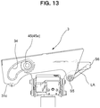
- the seat 5 tilts at least back and forth, and when the seated person starts standing up, the seat 5 moves while tilting forward together with the front-rear swing part 3, as illustrated in FIG. 13 .
- the engagement pin 81aX being the engaging part 81X illustrated in FIG. 21(c) settles on the sliding surface 40X in the front of the recess 82aX being the engaged part 82X.
- the seat 5 starts moving while tilting rearward in accordance with a relationship of the center-of-gravity position between the back and the seat, due to the presence of the back 6.
- the engagement pin 81aX being the engaging part 81X engages with the recess 82aX being the engaged part 82X.
- grooves are provided in a linked manner in an orthogonal direction, and a buffer material 82z such as rubber is embedded.
- the buffer material 82z is for avoiding collision of the engagement pin 81aX with the wall of the recess 82aX a shock or an abnormal noise caused, and after colliding with the buffer material 82z.
- the engagement pin 81aX collides with the buffer material 82z and fitted into the recess 82aX.
- control mechanism 8X switches the locked state of the seat 5 between when the seated person leaves the seat and when sitting on the seat, and thus, may be called a “seat-leaving and seat-sitting automatic stopper mechanism".
- a flange part 31b is provided on the plate member PM of the front-rear swing part 3 being the movable portion in which the guide hole 34 is provided, that is, on a vertical surface 31a of the rail plate 31, and a guide surface 31b1 for moving the bearing 45a being the rolling body 45 in the longitudinal direction is provided at a position extending in the lateral direction of the flange part 31b, that is, in the horizontal direction in the attached state.
- a lateral dimension w1 of the guide surface 31b1 is greater than a thickness t1 of the rail plate 31 being the plate member PM.
- the guide surface 31b1 is integrally formed of metal together with the rail plate 31. As illustrated in FIG. 3 and the like, the flange part 31b has a shape that goes around the circumference of the guide hole 34 opened in the vertical surface.
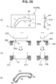
- the flange part 31b is configured by plastic deformation processing of the plate member PM around the guide hole 34, and specifically, by adopting burring processing.
- burring processing a pilot hole is opened in a plate member, the periphery of the pilot hole is fixed with a jig and in this state, the edge of the pilot hole is raised, by pressing with a tool larger than the pilot hole, to form a flange part, and thus, a cylindrical flange is generally formed. So far, burring processing has only been utilized for forming tapped holes and the like and has not been considered for producing a structure for guiding a rolling body.
- a pilot hole 34x corresponding to the shape of the guide hole 34 is opened with a slightly smaller size than the guide hole 34, as illustrated in FIG. 28(b) .
- the periphery of the pilot hole 34x is fixed with a jig 34Z along the shape of the guide hole 34, and in this state, pressing is performed with a tool 34Y that is larger than the pilot hole 34x and corresponds to the inner circumferential shape of the guide hole 34.
- the flange part 31b extending in the lateral direction via a portion R from the vertical surface 31a is formed over the entire circumference of the guide hole 34, and the flange part 31b directed in this lateral direction is substantially the pressure-receiving area.
- the lateral dimension of the guide surface 31b1 is substantially uniform over the entire circumference.
- the manufacturing means for the guide hole 34 is selected based on the conditions that the guide surface 31b1 is smooth, the guide surface 31b1 has strength, and the manufacturing cost is low. Fine blanking processing and other processing were also tried, however, it turned out that, even though the fine blanking processing relatively likely to be selected was excellent in forming a smooth guide surface, the plate member needed to have a considerable thickness to obtain strength. Thus, the fine blanking processing could not be adopted due to its inappropriate cost and other processing also did not satisfy the conditions above. Overall, it turned out that burring processing met these conditions very suitably.
- the flange part 31b formed in this way extends outward from the pair of rail plates 31, 31, rather than inward in the left-right direction, and the guide surface 31b1 being a rolling surface is formed outside the rail plates 31.
- one end (the front end or the rear end) of the guide hole 34 is formed with a so-called shockless part in which the radius of curvature is changed, so that as the bearing 45a approaches the end due to an operation of the seat 5, the operation speed of the seat 5 is reduced by performing control so that the center of gravity of the seat 5 is lifted.
- the flange part 31b1 made by burring is designed to withstand the shock caused during this time.
- a lower region of the guide hole 34 causes the bearing 45a being the rolling body 45 to abut against the lower region of the guide hole 34 to support the bearing 45a and the flange part 31b contributes to supporting the load during this time.
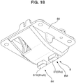
- the flange part 31b includes an upper-side first flange area A1 supporting the back and forth movement of the bearing 45a being the rolling body 45 when the seat 5 operates back and forth, a front-side second flange area A2 supporting a portion where the bearing 45a being the rolling body 45 reaches the front end of the guide hole 34 when the seated person leans against the back 6, and a rear-side third flange area A3 supporting a portion where the bearing 45a being the rolling body 45 reaches the rear end of the guide hole 34 when the seated person leans forward.
- the flange part 31b includes a lower-side fourth flange area A4 supporting the bearing 45a being the rolling body 45 when the left-right support state is unbalanced. This structure remains similar, even if the guide hole 34 is formed at the side of the support portion and the bearing 45a being the rolling body 45 is disposed at the side of the movable portion.
- the guide hole 34 is formed in the vertical surface of movable portion or the support portion of the chair and moves while receiving the load applied by seated person.
- the movable portion is supported at two locations on the front and rear side by the support portion including a guide structure configured by the rolling body 45 and the guide hole 34.
- the other movable portion of the chair is supported by the link arm LA, any one of the front and rear support structures is configured by the above-described rolling body 45 and the guide surface 31b1, and the other is configured by a different support structure, that is, in this embodiment, of the link structure.
- the back 6 is arranged behind the seat 5 and the backrest 62 is configured to be supported by the back frame 61 via the operating mechanism 6M.
- a back inner cover 63 is attached to the back frame 61, an opening 63a is provided in the back inner cover 63, and the backrest 62 is operatively supported by the back frame 61 via the opening 63a.
- the backrest 62 includes a cushion arranged on the front surface of a back plate 62a and the backrest 62 is entirely covered by an upholstery fabric.
- a lower end of the backrest 62 is disposed at a predetermined distance above the seat surface and the backrest 62 is supported on a back surface side by a back support part 61a at an upper end of the back frame 61 via the operating mechanism 6M.
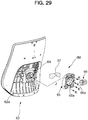
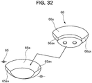
- the operating mechanism 6M includes: a base part 64 fixed to or formed integrally with the back plate 62a included in the backrest 62 and including an elastic member 65 arranged on a back surface side of the base part 64; a tilting part 65 disposed at a position adjacent to the base part 64 and including a guide part 65a recessed in a tapered shape at the back surface side, the center of the guide part 65a being open in the front-rear direction; and a pressing tool 66 including a convex guide part 66a corresponding to the guide part 65a on the front surface side, the pressing tool 66 being fixed to the base part 64 via the opening of the tilting part 65 in a state where the guide part 66a is fitted into the guide part 65a, as illustrated by an arrow J in FIG.
- a configuration of the operating mechanism 6M is such that the tilting part 65 is pulled and passed through the opening of the back inner cover 63 to be fixed by a screw to the back support part 61a at the upper end side of the back frame 61. That is, as illustrated in FIG. 31 , the pressing tool 66 is fixed to the base part with the tilting part 65 interposed therebetween, and thus, the pressing tool 66 is integrally formed with the base part 64 to form a part of the base part 64.
- the tilting part 65 can move freely in the gap between the base part 64 and the pressing tool 66, however, a configuration is such to allow for free movement of the tilting part 65, it is necessary to compress an elastic body 67 interposed between the tilting part 65 and the base part 64 against the elastic force.
- the elastic body 67 exerts a force on the guide part 65a of the tilting part 65 in a direction where the guide part 65a is constantly fitted in the guide part 66a of the pressing tool 66.
- the recess guide part 65a of the tilting part 65 has a substantially partially elliptical mortar-like shape including at least one valley line 65ax (two in this embodiment), the convex guide part 66a of the pressing tool 66 has a curved shape having at least one ridge line 66ax (two in this embodiment) fitted smoothly into the valley line 65ax, and the valley line 65ax and the ridge line 66ax can be fitted into each other.
- the convex guide part 66a is similar to a shape obtained by eliminating a part of an elliptical sphere, and the ridge line 66ax is formed along a line by a guide surface 66a intersected on the long axis side of the elliptical sphere. In a corresponding position of the matching recess guide part 65a, the valley line 65ax is also formed along a line by the intersected guide surface 65a. The reason therefore is that a spherical body and a spherical surface-receiving seat do not have directionality and cannot perform a positioning function.
- the convex guide part 66a and the recess guide part 65a are not limited to the mortar-like shape and the shape of the elliptical sphere, as long as they have different shapes that uniquely determine the directionality during fitting.
- the guide parts 66a, 65a need to be configured of a smooth continuous surface.
- the ridge line 66ax and the valley line 65ax are provided to enhance the positioning function during fitting.
- urethane is used for the elastic body 67, and as illustrated in FIG. 29 , the elastic body 67 is arranged from the left and right corner parts to the upper edge portion of the upper half of the rectangular plate-shaped base part 64. As illustrated in FIG. 31 , the thickness dimension of the elastic body 67 is set to achieve an appropriately compressed state in a state where the pressing tool 66 is attached to the base part 64, the tilting part 65 is attached to the back support part 61a of the back frame 61, and the guide part 66a of the pressing tool 66 and the guide part 65a of the tilting part 65 are fitted into each other.
- the elastic body 67 is not provided in the lower half of the base part 64 where there is little occasion to perform a function in a substantially, however, provision of the elastic body 67 in this position shall not be precluded.
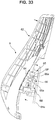
- FIG. 33 illustrates a rearward tilted state when a load is applied to the upper part of the back 6, and FIG. 34 is a plane cross section thereof. Further, FIG. 35 illustrates a turning operation of the back 6 in a case where the seated person twists its body and the like.
- the backrest 62 is disposed in a positional relationship where the backrest 62 moves against the elastic reaction force in the rearward direction and the turning direction while being supported by the elastic body 67, and a configuration is such that, when the elastic body 67 is deformed to the front, rear, right, or left in accordance with the amount of turning movement in the front, rear, right, or left directions, the reaction force returning the backrest 62 to a neutral position increases.
- the turning direction includes a turning movement in the left-right direction in front view, as illustrated in FIG. 35 , and further, in a clockwise or counterclockwise direction in front view.
- the guide part 65a of the tilting part 65 and the guide part 66a of the pressing tool 66 included in the base part 64 are guided to and stopped in a reference position illustrated in FIG. 31 because of the shape of the guide parts 66a, 65a by pressure contact with the elastic body 67. Subsequently, when the pressure contact is loosened due to an elastic member 67 being compressed by a load being applied due to receiving pressure from the seated person, the guide part 65a of the tilting part 65 and the guide part 66a of the pressing tool 66 included in the base part 64 are at least partly separated, as illustrated in FIGS. 33 , 34 , and 35 , so that the backrest 62 moves freely.
- the base part 64 and the tilting part 65 relatively move relative to the reference position in accordance with an amount of the received pressure and when the load is removed, the operating position is automatically returned, along the guide parts 66a, 65a, to the neutral position of FIG. 31 where the ridge line 66ax and the valley line 65ax coincide with each other.
- the backrest 62 is configured so that a gap SP between the guide parts 66a, 65a widens in accordance with a movement in the rear direction with respect to the back frame 61, and as a result, a turning range in the left-right direction expands and a return reaction force generated when the load is removed increases in accordance with the amount of turning movement in both the left and right directions.
- the base part 64 and the tilting part 65 are provided with engaging parts 64b, 65b configured to restrict a relative movement of the base part 64 and the tilting part 65 in collaboration with the guide parts 65a, 66a.
- the base part 64 includes an upright wall 64c at a peripheral edge, and a window 64b1 to be the engaging part 64b opens in a rectangular shape in the upright wall 64c.
- an L-shaped claw 65b1 to be the engaging part 65b is formed at a position displaced downward on the front side.
- the base part 64 and the tilting part 65 are assembled with the claw 65b1 loosely fitted in the window 64b1, and a movable range of the tilting part 65 with respect to the base part 64 is restricted to a range where the claw 65b1 can move in the window 64b1.
- a part of the backrest load is also supported in this restriction portion.
- the left-right turning operation of the back 6 occurs with respect to the back frame 61 and the seat 5 is attached to the front-rear swing part 3 to which the back frame 61 is attached, and thus, the back frame 61 and the seat 5 integrally swing in the left-right direction in front view, however, the backrest 62 further performs a different movement separately from the left-right turning operation of the seat 5 and the back frame 61.
- the base part 64 is attached to the backrest 62 and the tilting part 65 is attached to the side of the back frame 61, however, a configuration may be so that the base part 64 is attached to the side of the back frame 61 and the tilting part 65 is attached to the side of the backrest 62.
- the seat 5 is configured to be supported to be swingable to the front, rear, right, or left with respect to the support base part 2, however, a feeling of pressure on a femoral region of the left and right legs of the seated person sitting on the chair configured to swing to front, rear, right, or left, may change to be unbalanced depending on the posture of the seated person.
- the back 6 is provided to tilt rearward behind the seat 5 and when the back 6 tilts rearward, the seat 5 moves together with the back 6 and performs an operation in which the front part of the seat 5 rises relative to the back part of the seat 5 which descends, and as a result, the seated person may experience a feeling of pressure on the femoral region of the legs when leaning rearward and anxiety or instability due to the legs of the seated person being lifted in the air.
- this chair is provided with a deformation part 5X configured to change its shape in the up-down direction when receiving the load applied by seated person on a front part 5f of the seat 5.
- the deformation part 5X is provided at a position receiving the weight of the legs of the seated person, and is configured to deform downward when receiving the weight of the legs and to return upward when the weight of the legs is removed.
- a cushion material 54 covered by a non-illustrated upholstery fabric is arranged on the seat inner shell 53, and the seat outer shell 51 is attached below the seat inner shell 53.
- the seat inner shell 53 is configured by connecting a rear part 53a and a front part 53b with a resin hinge part 53c, and the front part 53b is elastically deformed with respect to the rear part 53a with the resin hinge part 53c as a boundary. Together with this deformation, the cushion material 54 is also deformed, and thus, these portions configure the deformation part 5x.
- the seat outer shell 51 is fixed to the front-rear swing part 3, and the rear part 53a of the seat inner shell 53 is attached above the seat outer shell 51.
- the deformation part 5x including the front part 53b of the seat inner shell 53 is deformed toward the seat outer shell 51.
- a front seat lower cover 55 is attached to the front part 53b forming the deformation part 5X of the seat inner shell 53, with the seat outer shell 51 interposed therebetween.
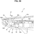
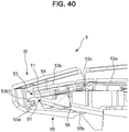
- FIG. 15 gives the impression that the front seat lower cover 55 is attached to the front part of the seat outer shell 51, the front seat lower cover 55 is actually arranged below the front part of the seat outer shell 51 in a non-connected state and is coupled to the deformation part 5X of the seat inner shell 53 above, as illustrated in FIGS. 39 and 40 . As illustrated in FIG.
- the left-right dimensions of the front seat lower cover 55 correspond substantially to the left-right dimensions of the front part 53b of the seat inner shell 53, and thus, a base end 55a of the front seat lower cover 55 is attached to an engaged part 53b1 (refer to FIGS. 39 and 40 ) set in the front part 53b of the seat inner shell 53, with the seat outer shell 51 interposed therebetween and a rear end 55b of the front seat lower cover 55 is shaped to extend rearward and downward along the seat outer shell 51.
- compression springs 56 being elastic bodies are arranged at positions compressed between the front part 53b of the seat inner shell 53 and the front part of the seat outer shell 51.
- a resin hinge 53c is shaped as a corrugated plate having a series of uneven portions, and the deformation part 5X has a structure that easily causes, in accordance with an unbalanced load received in a left-side region and a right-side region of the seat 5, regardless of the up-down direction, torsional deformation so that one side of the seat 5 in the left-right direction is lifted higher than the other side.
- a fixed attachment part 91 extending upward is attached to an arm attachment part 23 of the support base part 2 to bypass the seat 5 and even if the seat 5 swings to the front, rear, right, or left, the fixed attachment part 91 remains in a fixed position that does not interfere with the seat 5.
- a movable cover mechanism 92 in which a plurality of covers are combined is disposed below the seat 5 to not interfere with the relative operation of the front-rear swing part 3 and the left-right swing part 4 and to hide the front-rear swing part 3 and the left-right swing part 4.
- a front-rear swing part 3 being a movable portion that moves a state of receiving a load applied by seated person is configured to be operable to the front, rear, right, or left via a left-right swing parts 4 being the support base portion
- a flange part 31b is provided on the vertical surface 31a of a plate member MP of the front-rear swing part 3 being the movable portion
- the flange part 31b has a guide surface 31b1 extending in a lateral direction and for moving a rolling body 45 in the longitudinal direction; and a lateral dimension of the guide surface 31b1 is greater than a thickness of the plate member PM.
- the flange part 31b and the portion of the plate member MP forming the vertical surface 31a around the flange part 31 b are integrally formed of metal; the flange part 31b has a shape formed around the entire circumference of a guide hole 34 opened in the vertical surface 31a.
- the rolling body 45 is provided so as to be roll independently on the left and right along the guide surface 31b1.
- the pressure receiving area of the guide hole 34 in contact with the rolling body 45 is increased, and load distribution can be achieved, resulting in improved durability. Furthermore, by providing the flange part 31b integrally with the plate member MP being the movable portion with metal, high strength can be secured, and a rib effect by the flange part 31b can also be expected. At the result, the rolling body 45 can be reliably supported and easily rolled without thickening the plate member MP. Further, the chair that moves while sitting is particularly applied high load, so the present invention is particularly effective.
- front-rear swing part 3 being the movable portion receives a load applied by seated person and moves in the front, rear, left, or right under the support of the left-right swing part 4 b, even if the shaft center positions of the left and right rolling bodies 45 are shifted from the guide surface 31b1, operation can be secured.
- one of the rolling body 45 can be in contact with the lower edge of the guide surface 31b and the other with the upper edge of the guide surface 31b, and the rolling body 45 can perform an operation in which one of left and right moves rolling body forward or rotates backward, and the other moves backward or rotates backward, so that it is possible to appropriately respond to right and left unbalanced external force or movement.
- the lateral dimension of the guide surface 31b1 is substantially uniform over the entire circumference, therefore, the region in contact with the rolling body 45 can be secured over the entire circumference.
- the flange part 31b is formed by plastic deformation processing of the plate member MP around the guide hole 34, the hardness of the flange part 31b can be increased by work hardening across the entire circumference, and at the same time, a smooth surface can be obtained across the entire circumference by the ironing effect at the time of processing.
- the flange part 31b is formed to extend from the guide hole 34 outward the left-right direction of the chair, therefore, the width of support is wider than that of the shape extending from the guide hole 34 inward the left-right directions, and stable support of the chair is possible.
- an end part of the guide hole 34 has a shockless shape that lefts the center of gravity of the movable portion in order to mitigate a shock due to the collision with the rolling body 45,therefore, the synergetic effect of the formation of the flange portion 31 b and the shockless can improve the durability and the strength.
- the rolling body can not withstand strength when the rolling body 45 are resin so on.
- the shortest dimension D from the both end parts of the guide hole 34 to the edge of the plate member MP is set to at least 15 mm or more.
- the plate member cannot withstand the loads during processing or in use and is deformed.
- the thickness of a thin plate of 2 to 6 mm is set to 15 mm or more, an appropriate processing can be performed without deforming the plate member MP.
- the front-rear swing part 3 being the movable portion is supported by the left-right swing part 4 being the supporting portion at two locations on the front and rear, and any one of the front and rear support structures of the chair, that is, in this embodiment the front support structure includes the rolling elements 45 and the guide surfaces 31b1, and the other, that is, in this embodiment the rear support structure is configured by a different link support structure.
- the front and rear support structures are different, a load that is biased forward and backward is applied, the load burden between the rolling body and the guide surface increases, the left and right unbalanced behaviors are easily collected, and it is in particularly effective to apply to the present invention.
- the guide hole 34 is formed in the movable portion of the chair, and the bearing 45a being the rolling body 45 is a supporting portion. Then, the guide hole 34 may be provided on the support portion side, and the bearing 45a being the rolling element 45 may be configured opposite to the movable portion of a chair.
- the movable part is not limited to the front-rear swing part as in the above embodiment as long as it is applied between the movable part and the supporting part, and in the case where the left-right swing part is supported by the guide hole and the bearing, the above-described burring structure may be applied to the left-right swing parts.
Landscapes
- Chairs Characterized By Structure (AREA)
- Chairs For Special Purposes, Such As Reclining Chairs (AREA)
Applications Claiming Priority (1)
| Application Number | Priority Date | Filing Date | Title |
|---|---|---|---|
| PCT/JP2017/022761 WO2018235176A1 (fr) | 2017-06-20 | 2017-06-20 | Chaise |
Publications (3)
| Publication Number | Publication Date |
|---|---|
| EP3643203A1 true EP3643203A1 (fr) | 2020-04-29 |
| EP3643203A4 EP3643203A4 (fr) | 2020-11-11 |
| EP3643203B1 EP3643203B1 (fr) | 2022-03-23 |
Family
ID=64736898
Family Applications (1)
| Application Number | Title | Priority Date | Filing Date |
|---|---|---|---|
| EP17915037.0A Active EP3643203B1 (fr) | 2017-06-20 | 2017-06-20 | Chaise |
Country Status (6)
| Country | Link |
|---|---|
| US (1) | US11096495B2 (fr) |
| EP (1) | EP3643203B1 (fr) |
| JP (2) | JP6900478B2 (fr) |
| CN (1) | CN110636780B (fr) |
| CA (1) | CA3063824C (fr) |
| WO (1) | WO2018235176A1 (fr) |
Families Citing this family (6)
| Publication number | Priority date | Publication date | Assignee | Title |
|---|---|---|---|---|
| JP6900478B2 (ja) * | 2017-06-20 | 2021-07-07 | コクヨ株式会社 | 椅子 |
| CA3113842C (fr) * | 2018-10-19 | 2023-09-05 | Kokuyo Co., Ltd. | Chaise |
| CN112998462B (zh) * | 2021-04-22 | 2025-08-08 | 安吉德卡办公系统有限公司 | 一种可以左右摆动的椅子 |
| JP7484829B2 (ja) | 2021-06-29 | 2024-05-16 | トヨタ自動車株式会社 | 椅子 |
| JP7571678B2 (ja) | 2021-06-29 | 2024-10-23 | トヨタ自動車株式会社 | 足漕ぎ運動システム |
| CN120265184A (zh) * | 2022-10-31 | 2025-07-04 | B4K有限公司 | 椅子 |
Family Cites Families (35)
| Publication number | Priority date | Publication date | Assignee | Title |
|---|---|---|---|---|
| DE7731339U1 (de) * | 1977-10-11 | 1978-01-26 | Fa. Willibald Grammer, 8450 Amberg | Fahrzeugsitz |
| FR2471813B1 (fr) | 1979-12-21 | 1985-10-11 | Rolls Royce | Dispositif de traitement de fluide |
| US5603551A (en) | 1996-01-16 | 1997-02-18 | Sheehan; Kelly | Gravitational resistant positional chair |
| JPH10129A (ja) | 1996-04-15 | 1998-01-06 | Tanaka Denki Kogyo Kk | 揺り椅子 |
| EP1172049A1 (fr) | 2000-02-18 | 2002-01-16 | Sugatsune Kogyo Co., Ltd. | Siege a dossier et dispositif amortisseur rotatif |
| JP3789738B2 (ja) | 2000-07-31 | 2006-06-28 | 株式会社イトーキ | 家具類の軸受け構造 |
| CA2525902A1 (fr) * | 2001-01-25 | 2002-07-25 | Jsj Seating Company Texas, L.P. | Fauteuil de bureau |
| US6890030B2 (en) * | 2001-07-31 | 2005-05-10 | Haworth, Inc. | Chair having a seat with adjustable front edge |
| JP2004008440A (ja) * | 2002-06-06 | 2004-01-15 | Fuji Sogyo:Kk | 水平維持装置 |
| JP4875304B2 (ja) * | 2005-02-09 | 2012-02-15 | 株式会社イトーキ | 椅子 |
| US10383445B2 (en) | 2007-10-10 | 2019-08-20 | Hector Serber | Dynamically balanced seat assembly having independently and arcuately movable backrest and method |
| JP2009293693A (ja) | 2008-06-05 | 2009-12-17 | Tokai Univ | 制振装置 |
| US8613482B2 (en) * | 2010-02-08 | 2013-12-24 | Hangzhou Zhongtai Industrial Co., Ltd. | Chair chassis |
| JP2011161123A (ja) * | 2010-02-15 | 2011-08-25 | Itoki Corp | 椅子 |
| EP2387913B1 (fr) | 2010-05-21 | 2013-03-27 | Karl-Heinz Brändle | Dispositif destiné à l'amélioration du maintien en position assise de l'humain |
| CA2802187A1 (fr) * | 2010-06-11 | 2011-12-15 | Okamura Corporation | Chaise |
| GB201014953D0 (en) * | 2010-09-08 | 2010-10-20 | Birkbeck Hilary R | Slide chair action |
| KR101358007B1 (ko) * | 2012-04-05 | 2014-02-04 | 부호체어원(주) | 의자의 좌판 각도 조절장치 |
| JP6000085B2 (ja) | 2012-05-29 | 2016-09-28 | 株式会社クオリ | ロッキング機構付格納椅子 |
| JP6343118B2 (ja) * | 2012-05-31 | 2018-06-13 | 株式会社イトーキ | ネスティング可能な椅子 |
| WO2013177690A1 (fr) * | 2012-06-01 | 2013-12-05 | Duke Aaron | Siège et ensemble de commande d'inclinaison de siège |
| DE202012006249U1 (de) | 2012-06-28 | 2013-10-02 | Karl-Heinz Brändle | Stuhl oder Stützkörper |
| JP6141617B2 (ja) * | 2012-10-19 | 2017-06-07 | 株式会社岡村製作所 | 進退装置、およびそれを用いた椅子 |
| JP6353213B2 (ja) * | 2013-11-11 | 2018-07-04 | 株式会社イトーキ | ロッキング椅子 |
| US10881208B2 (en) * | 2016-02-23 | 2021-01-05 | Kokuyo Co., Ltd. | Chair and seat support mechanism |
| JP6735826B2 (ja) * | 2016-06-20 | 2020-08-05 | コクヨ株式会社 | 椅子及び座の支持機構 |
| EP3473135B1 (fr) * | 2016-06-20 | 2024-09-04 | Kokuyo Co., Ltd. | Chaise et mécanisme de support de siège |
| US10986924B2 (en) * | 2016-06-20 | 2021-04-27 | Kokuyo Co., Ltd. | Chair and seat support mechanism |
| CA3044170C (fr) * | 2016-12-20 | 2022-03-29 | Kokuyo Co., Ltd. | Chaise |
| CN110022724B (zh) * | 2016-12-20 | 2022-11-11 | 国誉株式会社 | 椅子和椅子的罩构件 |
| CN109982609B (zh) * | 2016-12-20 | 2022-09-23 | 国誉株式会社 | 椅子 |
| EP3643206B1 (fr) * | 2017-06-20 | 2024-09-04 | Kokuyo Co., Ltd. | Siège |
| JP6900478B2 (ja) * | 2017-06-20 | 2021-07-07 | コクヨ株式会社 | 椅子 |
| EP3643205B1 (fr) * | 2017-06-20 | 2024-07-03 | Kokuyo Co., Ltd. | Chaise |
| CN110636781B (zh) * | 2017-06-20 | 2023-10-03 | 国誉株式会社 | 椅子 |
-
2017
- 2017-06-20 JP JP2019524759A patent/JP6900478B2/ja active Active
- 2017-06-20 CN CN201780090958.6A patent/CN110636780B/zh active Active
- 2017-06-20 WO PCT/JP2017/022761 patent/WO2018235176A1/fr not_active Ceased
- 2017-06-20 EP EP17915037.0A patent/EP3643203B1/fr active Active
- 2017-06-20 US US16/614,954 patent/US11096495B2/en active Active
- 2017-06-20 CA CA3063824A patent/CA3063824C/fr active Active
-
2021
- 2021-06-16 JP JP2021100363A patent/JP7130094B2/ja active Active
Also Published As
| Publication number | Publication date |
|---|---|
| CA3063824A1 (fr) | 2019-12-09 |
| CN110636780B (zh) | 2023-03-10 |
| EP3643203A4 (fr) | 2020-11-11 |
| US20200196763A1 (en) | 2020-06-25 |
| CA3063824C (fr) | 2022-10-11 |
| EP3643203B1 (fr) | 2022-03-23 |
| WO2018235176A1 (fr) | 2018-12-27 |
| JP6900478B2 (ja) | 2021-07-07 |
| US11096495B2 (en) | 2021-08-24 |
| JP2021137644A (ja) | 2021-09-16 |
| JP7130094B2 (ja) | 2022-09-02 |
| CN110636780A (zh) | 2019-12-31 |
| JPWO2018235176A1 (ja) | 2020-04-16 |
Similar Documents
| Publication | Publication Date | Title |
|---|---|---|
| EP3643203B1 (fr) | Chaise | |
| EP3643205B1 (fr) | Chaise | |
| EP3643206B1 (fr) | Siège | |
| CN104334403B (zh) | 座椅滑动装置 | |
| KR20130111950A (ko) | 의자 | |
| CN102089185A (zh) | 座椅靠背装置 | |
| US20110181086A1 (en) | Support structure for a back part and/or a seat of a seat assembly and seat assembly comprising such a support structure | |
| JP2013132403A (ja) | 椅子 | |
| EP3643204B1 (fr) | Chaise | |
| US12114784B2 (en) | Chair having a movable seat | |
| JP6952509B2 (ja) | 椅子 |
Legal Events
| Date | Code | Title | Description |
|---|---|---|---|
| STAA | Information on the status of an ep patent application or granted ep patent |
Free format text: STATUS: THE INTERNATIONAL PUBLICATION HAS BEEN MADE |
|
| PUAI | Public reference made under article 153(3) epc to a published international application that has entered the european phase |
Free format text: ORIGINAL CODE: 0009012 |
|
| STAA | Information on the status of an ep patent application or granted ep patent |
Free format text: STATUS: REQUEST FOR EXAMINATION WAS MADE |
|
| 17P | Request for examination filed |
Effective date: 20191119 |
|
| AK | Designated contracting states |
Kind code of ref document: A1 Designated state(s): AL AT BE BG CH CY CZ DE DK EE ES FI FR GB GR HR HU IE IS IT LI LT LU LV MC MK MT NL NO PL PT RO RS SE SI SK SM TR |
|
| AX | Request for extension of the european patent |
Extension state: BA ME |
|
| DAV | Request for validation of the european patent (deleted) | ||
| DAX | Request for extension of the european patent (deleted) | ||
| A4 | Supplementary search report drawn up and despatched |
Effective date: 20201008 |
|
| RIC1 | Information provided on ipc code assigned before grant |
Ipc: A47C 9/00 20060101ALI20201002BHEP Ipc: A47C 3/026 20060101AFI20201002BHEP |
|
| GRAP | Despatch of communication of intention to grant a patent |
Free format text: ORIGINAL CODE: EPIDOSNIGR1 |
|
| STAA | Information on the status of an ep patent application or granted ep patent |
Free format text: STATUS: GRANT OF PATENT IS INTENDED |
|
| INTG | Intention to grant announced |
Effective date: 20211122 |
|
| GRAS | Grant fee paid |
Free format text: ORIGINAL CODE: EPIDOSNIGR3 |
|
| GRAA | (expected) grant |
Free format text: ORIGINAL CODE: 0009210 |
|
| STAA | Information on the status of an ep patent application or granted ep patent |
Free format text: STATUS: THE PATENT HAS BEEN GRANTED |
|
| AK | Designated contracting states |
Kind code of ref document: B1 Designated state(s): AL AT BE BG CH CY CZ DE DK EE ES FI FR GB GR HR HU IE IS IT LI LT LU LV MC MK MT NL NO PL PT RO RS SE SI SK SM TR |
|
| REG | Reference to a national code |
Ref country code: GB Ref legal event code: FG4D |
|
| REG | Reference to a national code |
Ref country code: CH Ref legal event code: EP |
|
| REG | Reference to a national code |
Ref country code: DE Ref legal event code: R096 Ref document number: 602017055084 Country of ref document: DE |
|
| REG | Reference to a national code |
Ref country code: IE Ref legal event code: FG4D |
|
| REG | Reference to a national code |
Ref country code: AT Ref legal event code: REF Ref document number: 1476857 Country of ref document: AT Kind code of ref document: T Effective date: 20220415 |
|
| REG | Reference to a national code |
Ref country code: LT Ref legal event code: MG9D |
|
| REG | Reference to a national code |
Ref country code: NL Ref legal event code: MP Effective date: 20220323 |
|
| PG25 | Lapsed in a contracting state [announced via postgrant information from national office to epo] |
Ref country code: SE Free format text: LAPSE BECAUSE OF FAILURE TO SUBMIT A TRANSLATION OF THE DESCRIPTION OR TO PAY THE FEE WITHIN THE PRESCRIBED TIME-LIMIT Effective date: 20220323 Ref country code: RS Free format text: LAPSE BECAUSE OF FAILURE TO SUBMIT A TRANSLATION OF THE DESCRIPTION OR TO PAY THE FEE WITHIN THE PRESCRIBED TIME-LIMIT Effective date: 20220323 Ref country code: NO Free format text: LAPSE BECAUSE OF FAILURE TO SUBMIT A TRANSLATION OF THE DESCRIPTION OR TO PAY THE FEE WITHIN THE PRESCRIBED TIME-LIMIT Effective date: 20220623 Ref country code: LT Free format text: LAPSE BECAUSE OF FAILURE TO SUBMIT A TRANSLATION OF THE DESCRIPTION OR TO PAY THE FEE WITHIN THE PRESCRIBED TIME-LIMIT Effective date: 20220323 Ref country code: HR Free format text: LAPSE BECAUSE OF FAILURE TO SUBMIT A TRANSLATION OF THE DESCRIPTION OR TO PAY THE FEE WITHIN THE PRESCRIBED TIME-LIMIT Effective date: 20220323 Ref country code: BG Free format text: LAPSE BECAUSE OF FAILURE TO SUBMIT A TRANSLATION OF THE DESCRIPTION OR TO PAY THE FEE WITHIN THE PRESCRIBED TIME-LIMIT Effective date: 20220623 |
|
| REG | Reference to a national code |
Ref country code: AT Ref legal event code: MK05 Ref document number: 1476857 Country of ref document: AT Kind code of ref document: T Effective date: 20220323 |
|
| PG25 | Lapsed in a contracting state [announced via postgrant information from national office to epo] |
Ref country code: LV Free format text: LAPSE BECAUSE OF FAILURE TO SUBMIT A TRANSLATION OF THE DESCRIPTION OR TO PAY THE FEE WITHIN THE PRESCRIBED TIME-LIMIT Effective date: 20220323 Ref country code: GR Free format text: LAPSE BECAUSE OF FAILURE TO SUBMIT A TRANSLATION OF THE DESCRIPTION OR TO PAY THE FEE WITHIN THE PRESCRIBED TIME-LIMIT Effective date: 20220624 Ref country code: FI Free format text: LAPSE BECAUSE OF FAILURE TO SUBMIT A TRANSLATION OF THE DESCRIPTION OR TO PAY THE FEE WITHIN THE PRESCRIBED TIME-LIMIT Effective date: 20220323 |
|
| PG25 | Lapsed in a contracting state [announced via postgrant information from national office to epo] |
Ref country code: NL Free format text: LAPSE BECAUSE OF FAILURE TO SUBMIT A TRANSLATION OF THE DESCRIPTION OR TO PAY THE FEE WITHIN THE PRESCRIBED TIME-LIMIT Effective date: 20220323 |
|
| PG25 | Lapsed in a contracting state [announced via postgrant information from national office to epo] |
Ref country code: SM Free format text: LAPSE BECAUSE OF FAILURE TO SUBMIT A TRANSLATION OF THE DESCRIPTION OR TO PAY THE FEE WITHIN THE PRESCRIBED TIME-LIMIT Effective date: 20220323 Ref country code: SK Free format text: LAPSE BECAUSE OF FAILURE TO SUBMIT A TRANSLATION OF THE DESCRIPTION OR TO PAY THE FEE WITHIN THE PRESCRIBED TIME-LIMIT Effective date: 20220323 Ref country code: RO Free format text: LAPSE BECAUSE OF FAILURE TO SUBMIT A TRANSLATION OF THE DESCRIPTION OR TO PAY THE FEE WITHIN THE PRESCRIBED TIME-LIMIT Effective date: 20220323 Ref country code: PT Free format text: LAPSE BECAUSE OF FAILURE TO SUBMIT A TRANSLATION OF THE DESCRIPTION OR TO PAY THE FEE WITHIN THE PRESCRIBED TIME-LIMIT Effective date: 20220725 Ref country code: ES Free format text: LAPSE BECAUSE OF FAILURE TO SUBMIT A TRANSLATION OF THE DESCRIPTION OR TO PAY THE FEE WITHIN THE PRESCRIBED TIME-LIMIT Effective date: 20220323 Ref country code: EE Free format text: LAPSE BECAUSE OF FAILURE TO SUBMIT A TRANSLATION OF THE DESCRIPTION OR TO PAY THE FEE WITHIN THE PRESCRIBED TIME-LIMIT Effective date: 20220323 Ref country code: CZ Free format text: LAPSE BECAUSE OF FAILURE TO SUBMIT A TRANSLATION OF THE DESCRIPTION OR TO PAY THE FEE WITHIN THE PRESCRIBED TIME-LIMIT Effective date: 20220323 Ref country code: AT Free format text: LAPSE BECAUSE OF FAILURE TO SUBMIT A TRANSLATION OF THE DESCRIPTION OR TO PAY THE FEE WITHIN THE PRESCRIBED TIME-LIMIT Effective date: 20220323 |
|
| PG25 | Lapsed in a contracting state [announced via postgrant information from national office to epo] |
Ref country code: PL Free format text: LAPSE BECAUSE OF FAILURE TO SUBMIT A TRANSLATION OF THE DESCRIPTION OR TO PAY THE FEE WITHIN THE PRESCRIBED TIME-LIMIT Effective date: 20220323 Ref country code: IS Free format text: LAPSE BECAUSE OF FAILURE TO SUBMIT A TRANSLATION OF THE DESCRIPTION OR TO PAY THE FEE WITHIN THE PRESCRIBED TIME-LIMIT Effective date: 20220723 Ref country code: AL Free format text: LAPSE BECAUSE OF FAILURE TO SUBMIT A TRANSLATION OF THE DESCRIPTION OR TO PAY THE FEE WITHIN THE PRESCRIBED TIME-LIMIT Effective date: 20220323 |
|
| REG | Reference to a national code |
Ref country code: DE Ref legal event code: R097 Ref document number: 602017055084 Country of ref document: DE |
|
| PLBE | No opposition filed within time limit |
Free format text: ORIGINAL CODE: 0009261 |
|
| STAA | Information on the status of an ep patent application or granted ep patent |
Free format text: STATUS: NO OPPOSITION FILED WITHIN TIME LIMIT |
|
| PG25 | Lapsed in a contracting state [announced via postgrant information from national office to epo] |
Ref country code: MC Free format text: LAPSE BECAUSE OF FAILURE TO SUBMIT A TRANSLATION OF THE DESCRIPTION OR TO PAY THE FEE WITHIN THE PRESCRIBED TIME-LIMIT Effective date: 20220323 Ref country code: DK Free format text: LAPSE BECAUSE OF FAILURE TO SUBMIT A TRANSLATION OF THE DESCRIPTION OR TO PAY THE FEE WITHIN THE PRESCRIBED TIME-LIMIT Effective date: 20220323 |
|
| REG | Reference to a national code |
Ref country code: CH Ref legal event code: PL |
|
| REG | Reference to a national code |
Ref country code: BE Ref legal event code: MM Effective date: 20220630 |
|
| 26N | No opposition filed |
Effective date: 20230102 |
|
| PG25 | Lapsed in a contracting state [announced via postgrant information from national office to epo] |
Ref country code: LU Free format text: LAPSE BECAUSE OF NON-PAYMENT OF DUE FEES Effective date: 20220620 Ref country code: LI Free format text: LAPSE BECAUSE OF NON-PAYMENT OF DUE FEES Effective date: 20220630 Ref country code: IE Free format text: LAPSE BECAUSE OF NON-PAYMENT OF DUE FEES Effective date: 20220620 Ref country code: FR Free format text: LAPSE BECAUSE OF NON-PAYMENT OF DUE FEES Effective date: 20220630 Ref country code: CH Free format text: LAPSE BECAUSE OF NON-PAYMENT OF DUE FEES Effective date: 20220630 |
|
| PG25 | Lapsed in a contracting state [announced via postgrant information from national office to epo] |
Ref country code: SI Free format text: LAPSE BECAUSE OF FAILURE TO SUBMIT A TRANSLATION OF THE DESCRIPTION OR TO PAY THE FEE WITHIN THE PRESCRIBED TIME-LIMIT Effective date: 20220323 Ref country code: BE Free format text: LAPSE BECAUSE OF NON-PAYMENT OF DUE FEES Effective date: 20220630 |
|
| P01 | Opt-out of the competence of the unified patent court (upc) registered |
Effective date: 20230426 |
|
| PG25 | Lapsed in a contracting state [announced via postgrant information from national office to epo] |
Ref country code: IT Free format text: LAPSE BECAUSE OF FAILURE TO SUBMIT A TRANSLATION OF THE DESCRIPTION OR TO PAY THE FEE WITHIN THE PRESCRIBED TIME-LIMIT Effective date: 20220323 |
|
| PG25 | Lapsed in a contracting state [announced via postgrant information from national office to epo] |
Ref country code: MK Free format text: LAPSE BECAUSE OF FAILURE TO SUBMIT A TRANSLATION OF THE DESCRIPTION OR TO PAY THE FEE WITHIN THE PRESCRIBED TIME-LIMIT Effective date: 20220323 Ref country code: CY Free format text: LAPSE BECAUSE OF FAILURE TO SUBMIT A TRANSLATION OF THE DESCRIPTION OR TO PAY THE FEE WITHIN THE PRESCRIBED TIME-LIMIT Effective date: 20220323 |
|
| PG25 | Lapsed in a contracting state [announced via postgrant information from national office to epo] |
Ref country code: HU Free format text: LAPSE BECAUSE OF FAILURE TO SUBMIT A TRANSLATION OF THE DESCRIPTION OR TO PAY THE FEE WITHIN THE PRESCRIBED TIME-LIMIT; INVALID AB INITIO Effective date: 20170620 |
|
| PG25 | Lapsed in a contracting state [announced via postgrant information from national office to epo] |
Ref country code: MT Free format text: LAPSE BECAUSE OF FAILURE TO SUBMIT A TRANSLATION OF THE DESCRIPTION OR TO PAY THE FEE WITHIN THE PRESCRIBED TIME-LIMIT Effective date: 20220323 |
|
| PGFP | Annual fee paid to national office [announced via postgrant information from national office to epo] |
Ref country code: DE Payment date: 20250429 Year of fee payment: 9 |
|
| PGFP | Annual fee paid to national office [announced via postgrant information from national office to epo] |
Ref country code: GB Payment date: 20250501 Year of fee payment: 9 |
|
| PG25 | Lapsed in a contracting state [announced via postgrant information from national office to epo] |
Ref country code: TR Free format text: LAPSE BECAUSE OF FAILURE TO SUBMIT A TRANSLATION OF THE DESCRIPTION OR TO PAY THE FEE WITHIN THE PRESCRIBED TIME-LIMIT Effective date: 20220323 |