EP3643205B1 - Stuhl - Google Patents
Stuhl Download PDFInfo
- Publication number
- EP3643205B1 EP3643205B1 EP17914176.7A EP17914176A EP3643205B1 EP 3643205 B1 EP3643205 B1 EP 3643205B1 EP 17914176 A EP17914176 A EP 17914176A EP 3643205 B1 EP3643205 B1 EP 3643205B1
- Authority
- EP
- European Patent Office
- Prior art keywords
- guide
- seat
- tilting
- backrest
- chair
- Prior art date
- Legal status (The legal status is an assumption and is not a legal conclusion. Google has not performed a legal analysis and makes no representation as to the accuracy of the status listed.)
- Active
Links
Images















Classifications
-
- A—HUMAN NECESSITIES
- A47—FURNITURE; DOMESTIC ARTICLES OR APPLIANCES; COFFEE MILLS; SPICE MILLS; SUCTION CLEANERS IN GENERAL
- A47C—CHAIRS; SOFAS; BEDS
- A47C3/00—Chairs characterised by structural features; Chairs or stools with rotatable or vertically-adjustable seats
- A47C3/02—Rocking chairs
- A47C3/025—Rocking chairs with seat, or seat and back-rest unit, elastically mounted in a rigid frame
- A47C3/026—Rocking chairs with seat, or seat and back-rest unit, elastically mounted in a rigid frame with a central column, e.g. rocking office chairs; Tilting chairs
-
- A—HUMAN NECESSITIES
- A47—FURNITURE; DOMESTIC ARTICLES OR APPLIANCES; COFFEE MILLS; SPICE MILLS; SUCTION CLEANERS IN GENERAL
- A47C—CHAIRS; SOFAS; BEDS
- A47C3/00—Chairs characterised by structural features; Chairs or stools with rotatable or vertically-adjustable seats
- A47C3/02—Rocking chairs
- A47C3/025—Rocking chairs with seat, or seat and back-rest unit, elastically mounted in a rigid frame
- A47C3/0255—Rocking chairs with seat, or seat and back-rest unit, elastically mounted in a rigid frame pivotally mounted in the base frame, e.g. swings
-
- A—HUMAN NECESSITIES
- A47—FURNITURE; DOMESTIC ARTICLES OR APPLIANCES; COFFEE MILLS; SPICE MILLS; SUCTION CLEANERS IN GENERAL
- A47C—CHAIRS; SOFAS; BEDS
- A47C3/00—Chairs characterised by structural features; Chairs or stools with rotatable or vertically-adjustable seats
- A47C3/02—Rocking chairs
- A47C3/025—Rocking chairs with seat, or seat and back-rest unit, elastically mounted in a rigid frame
- A47C3/0257—Rocking chairs with seat, or seat and back-rest unit, elastically mounted in a rigid frame slidingly movable in the base frame, e.g. by rollers
-
- A—HUMAN NECESSITIES
- A47—FURNITURE; DOMESTIC ARTICLES OR APPLIANCES; COFFEE MILLS; SPICE MILLS; SUCTION CLEANERS IN GENERAL
- A47C—CHAIRS; SOFAS; BEDS
- A47C3/00—Chairs characterised by structural features; Chairs or stools with rotatable or vertically-adjustable seats
- A47C3/02—Rocking chairs
- A47C3/03—Locking members
-
- A—HUMAN NECESSITIES
- A47—FURNITURE; DOMESTIC ARTICLES OR APPLIANCES; COFFEE MILLS; SPICE MILLS; SUCTION CLEANERS IN GENERAL
- A47C—CHAIRS; SOFAS; BEDS
- A47C7/00—Parts, details, or accessories of chairs or stools
- A47C7/02—Seat parts
- A47C7/024—Seat parts with double seats
-
- A—HUMAN NECESSITIES
- A47—FURNITURE; DOMESTIC ARTICLES OR APPLIANCES; COFFEE MILLS; SPICE MILLS; SUCTION CLEANERS IN GENERAL
- A47C—CHAIRS; SOFAS; BEDS
- A47C7/00—Parts, details, or accessories of chairs or stools
- A47C7/36—Supports for the head or the back
- A47C7/40—Supports for the head or the back for the back
-
- A—HUMAN NECESSITIES
- A47—FURNITURE; DOMESTIC ARTICLES OR APPLIANCES; COFFEE MILLS; SPICE MILLS; SUCTION CLEANERS IN GENERAL
- A47C—CHAIRS; SOFAS; BEDS
- A47C7/00—Parts, details, or accessories of chairs or stools
- A47C7/36—Supports for the head or the back
- A47C7/40—Supports for the head or the back for the back
- A47C7/44—Supports for the head or the back for the back with elastically-mounted frame
- A47C7/448—Supports for the head or the back for the back with elastically-mounted frame with resilient blocks
-
- A—HUMAN NECESSITIES
- A47—FURNITURE; DOMESTIC ARTICLES OR APPLIANCES; COFFEE MILLS; SPICE MILLS; SUCTION CLEANERS IN GENERAL
- A47C—CHAIRS; SOFAS; BEDS
- A47C7/00—Parts, details, or accessories of chairs or stools
- A47C7/002—Chair or stool bases
- A47C7/006—Chair or stool bases with castors
Definitions
- a chair described in Patent Document 2 is configured such that an upper half of the back of automobile sheet turns around the vertical axis while storing repulsion.
- a chair described in Patent Document 3 is configured such that a back and a seat are integrally provided, a lower part of the seat is rollably supported around a fulcrum, and when rolling, the back and the seat compress rubber parts disposed around the lower part of the seat, and the repulsion that the back and the seat return to the reference position, is produced.
- a back and a seat are integrally provided.
- a configuration is enclosed that a part of the back is fixed at fulcrum, and centering around this fulcrum, the back and the seat deform in such a way as to twist leftward and rightward in a front view with the elasticity of the back and the seat in accordance with the movement of a seated person.
- Patent Document 5 A chair described in Patent Document 5 is configured such that a back and a seat are separated into a plurality of compartments, a part of the back and the seat among the components is partially separated so as to be partially easily deformed, accordingly the area between the compartments is easily twisted and the degree of deformation is increased.
- Patent Document 6 discloses a chair having the features of the preamble of claim 1.
- Patent Document 7 discloses a further related prior art chair.
- the back is turning-movable in a front view in a left-right direction, and when the load is applied, at least a part of guide parts of the operation mechanism is separated, and the back moves freely. Therefore, it can be easily adapted to various movement of the seated person. Further, when the seated person leaves a seat, the back reliably returns to the neutral position along guide parts. Therefore, even if the degree of freedom of back movement is increased, a plurality of chairs is easily uniform in appearance when the seated person leaves a seat. Further, it is possible to avoid the situation in that the initial condition of the chair is changed every time the seated person sits on the seat.
- the operation mechanism is provided with a base part and a tilting part, and includes a reference position, a guide part set at the side of the base part and a guide part set at the side of the tilting part are in pressure contact with each other to be guided by the shapes of the guide parts and stopped at the reference position, and when the pressure contact is loosened by the received pressure from the seated person, the base part and the tilting part can be relatively changed from the reference position in accordance with the degree of the received pressure.
- the back is configured such that a backrest is supported by a back frame via the operation mechanism, the back frame is erected at the rear of the seat, and the backrest is turning-movably attached to the back frame substantially clockwise or counterclockwise direction in a front view via the operation mechanism.
- the chair is configured such that the pressure contact of the both guide parts is formed by the elastic body and the elastic body is pressed by the received pressure, whereby the guide part of the tilting part and the guide part of the base part are separated.
- the operation mechanism includes: the base part fixed to the backrest and provided with the elastic body on the back surface side of the base part; the tilting part disposed at a position adjacent to the base part and including a guide part recessed in a tapered shape at the back surface side of the tilting part, the bottom part of the guide part having an opening; and a pressing tool including a guide part having a convex shape corresponding to the guide part of the tilting part on the front surface side of the pressing tool, the pressing tool being fixed to the base part via the opening of the tilting part in a state where the guide part of the pressing tool is fitted into the guide part of the tilting part, and the tilting part is fixed to the received pressure part provided at the upper end part of the back frame.
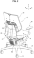
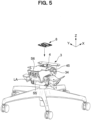
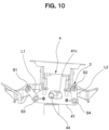
- the front-rear swing part 3 is provided between the seat 5 and the support base part 2 configured to support the seat 5, and the left-right swing part 4 is provided between the front-rear swing part 3 and the support base part 2. Behind the seat 5, a back 6 is arranged.
- the support base part 2 functions as a structured body for receiving the load applied by seated person, and in the support base part 2, a left-right pair of arm attachment parts 23 is integrally formed with the support base part 2 via a bearing base part 22 on both left and right sides of a support base main body 21 including a through hole 21a along an up-down direction into which an upper end of the supporting post 13 is inserted.
- a shaft swing damper 21b is attached to the hole 21a opening on the surface of the support base main body 21 in the front-rear direction and upper ends of left-right swing links L1, L2 are attached to holes 22a opening on the front and rear surfaces of the bearing base part 22, via swing support shafts S1, S2.
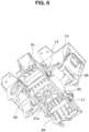
- the left-right swing part 4 includes a pair of plate-shaped link bases 41 disposed separated from each other in the front-rear direction to perform a swinging operation in the left-right direction with respect to the support base part 2, and a left-right swing main body 42 configured to connect the pair of link bases 41, 41.
- holes 41a, 41a are opened and the lower ends of the left-right swing links L1, L2 are attached via swing shafts S3, S4.
- FIG. 4 illustrates a state where the links L1, L2 are attached via the swing shafts S1 to S4. As illustrated in FIGS.
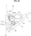
- the left-right swing main body 42 is provided with a unit attached hole 42a penetrating in the up-down direction, and a later-described left-right lock part 7 is attached to the unit attached hole 42a. That is, the left-right swing main body 42 is disposed in a suspended state to be swingable to the left and right with respect to the support base part 2 via the left-right swing links L1, L2, and the left-right swing links L1, L2 are attached so that the distance between the lower ends is smaller than the distance between the upper ends, as illustrated in FIG. 4 and the like.
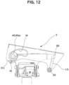
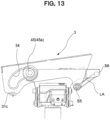
- the bearing 45 performs a relative movement with respect to the rear end side of the guide hole 34 at the front end of the front-rear swing part 3, so that the front end side of the front-rear swing part 3 is guided to a lower position, and the link arm LA approaches a horizontal posture.
- an operation is performed where the rear end of the front-rear swing part 3 is lifted to a higher position. That is, the front-rear swing part 3 performs an inclining operation so that the moving tip side is also lower in the front-rear direction.
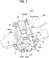
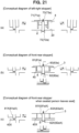
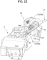
- a coil spring 83a being an elastic member 83 functions to bias the engagement pin 81a in a direction where the engagement pin 81a protrudes toward the sliding surface 40, a conversion mechanism 84 illustrated in FIGS. 16 and 17 is provided, the conversion mechanism 84 converting an operation of the operating member 152 into an operation in a direction in which the engagement pin 81a is separated from the sliding surface 40, and the conversion mechanism 84, the engagement pin 81a, and the coil spring 83a are integrally incorporated into a half-piece of the casing 80 to form with unitized.
- the guide hole 34 is formed in the vertical surface of the movable portion or the support portion of the chair and moves while receiving the load applied by seated person.
- the movable portion is supported at two locations on the front and rear side by the support portion including a guide structure configured by the rolling body 45 and the guide hole 34.
- the other movable portion of the chair is supported by the link arm LA, any one of the front and rear support structures is configured by the above-described rolling body 45 and the guide surface 31b1, and the other is configured by a different support structure, that is, in this embodiment, of the link structure.
- the convex guide part 66a and the recess guide part 65a are not limited to the mortar-like shape and the shape of the elliptical sphere, as long as they have different shapes that uniquely determine the directionality during fitting.
- the guide elements 66a, 65a need to be configured of a smooth continuous surface.
- the ridge line 66ax and the valley line 65ax are provided to enhance the positioning function during fitting.
- the base part 64 and the tilting part 65 relatively move relative to the reference position in accordance with an amount of the received pressure and when the load is removed, the operating position is automatically returned, along the guide parts 66a, 65a, to the neutral position of FIG. 31 where the ridge line 66ax and the valley line 65ax coincide with each other.
- the backrest 62 is configured so that a gap SP between the guide parts 66a, 65a widens in accordance with a movement in the rear direction with respect to the back frame 61, and as a result, a turning range in the left-right direction expands and a return reaction force generated when the load is removed increases in accordance with the amount of turning movement in both the left and right directions.
- the base part 64 and the tilting part 65 are assembled with the claw 65b1 loosely fitted in the window 64b1, and a movable range of the tilting part 65 with respect to the base element 64 is restricted to a range where the claw 65b1 can move in the window 64b1.
- a part of the backrest load is also supported in this restriction portion.
- the base part 64 is attached to the backrest 62 and the tilting part 65 is attached to the side of the back frame 61, however, a configuration may be so that the base part 64 is attached to the side of the back frame 61 and the tilting part 65 is attached to the side of the backrest 62.
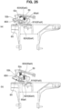
- the seat 5 is configured to be supported to be swingable to the front, rear, right, or left with respect to the support base part 2, however, a feeling of pressure on a femoral region of the left and right legs of the seated person sitting on the chair configured to swing to front, rear, right, or left, may change to be unbalanced depending on the posture of the seated person.
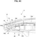
- a front seat lower cover 55 is attached to the front part 53b forming the deformation part 5X of the seat inner shell 53, with the seat outer shell 51 interposed therebetween.
- FIG. 15 gives the impression that the front seat lower cover 55 is attached to the front part of the seat outer shell 51, the front seat lower cover 55 is actually arranged below the front part of the seat outer shell 51 in a non-connected state and is coupled to the deformation part 5X of the seat inner shell 53 above, as illustrated in FIGS. 39 and 40 . As illustrated in FIG.
- the left-right dimensions of the front seat lower cover 55 correspond substantially to the left-right dimensions of the front part 53b of the seat inner shell 53, and thus, a base end 55a of the front seat lower cover 55 is attached to an engaged part 53b1 (refer to FIGS. 39 and 40 ) set in the front part 53b of the seat inner shell 53, with the seat outer shell 51 interposed therebetween and a rear end 55b of the front seat lower cover 55 is shaped to extend rearward and downward along the seat outer shell 51.
- a resin hinge 53c is shaped as a corrugated plate having a series of uneven portions, and the deformation part 5X has a structure that easily causes, in accordance with an unbalanced load received in a left-side region and a right-side region of the seat 5, regardless of the up-down direction, torsional deformation so that one side of the seat 5 in the left-right direction is lifted higher than the other side.
- the chair according to the present embodiment is configured such that the back 6 is arranged behind the seat 5, and the back 6 has an operation mechanism 6M turning-movable supporting the load received from a seated person in left-right direction in a front view, and when the load is applied, at least a part of guide parts 65a, 66a of the operation mechanism 6M is separated, and the back 6 moves freely, and when the applied load is removed, the back 6 automatically returns to the neutral position along the guide parts 65a, 66a.
- the back 6 is turning-movable in a front view in a left-right direction, and when the load is applied, at least a part of guide parts 65a, 66a of the operation mechanism 6M is separated, and the back 6 moves freely. Therefore, it can be easily adapted to various movement of the seated person. Further, when the seated person leaves a seat, the back 6 reliably returns to the neutral position along guide parts 65a, 66a. Therefore, even if the degree of freedom of back 6 movement is increased, a plurality of chairs is easily uniform in appearance when the seated person leaves a seat. Further, it is possible to avoid the situation in that the initial condition of the chair differs every time the seated person sits on the seat.
- the back 6 is configured such that a backrest 62 is supported by a back frame 61 via the operation mechanism 6M, the back frame 61 is erected at the rear of the seat 5, and the backrest 62 is turning movably attached to the back frame 61 substantially clockwise or counterclockwise direction in a front view via the operation mechanism 6M. Therefore, the operation mechanism 6M is configured only by introducing a simple turning mechanism or loose convex-concave structure in a part of the backrest 62.
- the back 6 is configured such that the backrest 62 is supported by the back frame 61 via the operation mechanism 6M, and the backrest 62 moves via the operation mechanism 6M having an elastic body 67 toward the rear direction and the turning direction against an elastic reaction force. Therefore, supporting force and returning force in accordance with size of displacement can be provided by moving the backrest 62 against the elastic reaction force of the elastic body 67.
- the seat 5 is swingable in the left-right direction in a front view, and the back 6 performs a left-right turning operation separated from the seat 5. Therefore, left-right swinging of the seat 5 and left-right turning operation of the backrest 62 work together through the seated person's posture. In consequence, it is possible to realize an appropriate support state in accordance with the seated person's posture.
- the operation mechanism 6M is provided with a base part 64 and a tilting part 65, and includes a reference position, a guide part 66a set at the side of the base part 64 and a guide part 65a set at the side of the tilting part 65 are in pressure contact with each other to be guided by the shapes of the guide parts 66a, 65a and stopped at the reference position, and when the pressure contact is loosened by the received pressure from the seated person, the base part 64 and the tilting part 65 can be relatively changed from the reference position in accordance with the degree of the received pressure. Therefore, while the operation mechanism 6M has a simple structure, the operation mechanism 6M has a function to return to the reference position when the applied load is removed, and can be incorporated as an operation unit for various intended use including the present embodiment.
- the chair is configured such that the pressure contact of the both guide parts 66a, 65a is formed by the elastic body 67 and the elastic body 67 is pressed by the received pressure, whereby the guide part 65a of the tilting part 65 and the guide part 66a of the base part 64 are separated. Therefore, the elastic body 67 can serve as a role to flexibly receive the load of the backrest and as a role to return the guide parts, 66a, 65a to the reference position.
- one guide part 65a has a substantially partially elliptical mortar-like shape including at least one valley line 65ax and the other guide part 66a has a curved shape having at least one ridge line 66ax fitted smoothly into the valley line 65ax, and the valley line 65ax and the ridge line 66ax can be fitted into each other.
- the positioning function at the reference position can be enhanced.
- the base part 64 and the tilting part 65 are provided with engaging parts 64b,65b configured to regulate a relative movement of the base part 64 and the tilting part 65 in collaboration with the guide parts 66a,65a, and a part of the load of the backrest is supported by these engaging parts, 64b, 65b. Therefore, it is possible to prevent the local load from concentrating on the guide parts, 6a, 65a.
- the chair illustrated in FIG.41 , 42 and 43 includes an operation mechanism 106M different from one of the above-described embodiments at the back to support turning-movably the load received from seated person in left-right direction in front view.
- the operation mechanism 106M is also configured such that when the load is applied, at least a part of guide parts, 165a, 166a of the operation mechanism is separated and the back moves freely, and when the applied load is removed, the operating position of the operation mechanism 160M automatically returns to the neutral position along the guide parts, 165a, 166a of the operation mechanism 106M.
- the operation mechanism 106M is provided with a base part 164 and a tilting part 165, and includes a reference position, a guide part 166a set at the side of the base part 164 and a guide part 165a set at the side of the tilting part 165 are in pressure contact with each other to be guided by the shapes of the guide parts 166a, 165a, and stopped at the reference position, and when the pressure contact is loosened by the received pressure from the seated person, the base part 164 and tilting part 165 can be relatively changed from the reference position in accordance with the degree of the received pressure.
- This function is also the same as one of the above-described embodiment.
- One guide part 166a is a shaft-shaped part 166 extended upward and downward, or leftward and rightward and the other guide part 165a is a V-groove leading the upper-lower or left-right shaft-shaped member 166 to the center position.
- a semicircle groove bottom 165a1 that defines the reference position at the center of the groove is formed.
- the tilting part 165 is freely movable in a gap between the base part 164 and the shaft shaped member 166. For the free movement, it is configured so as to be required to press an elastic body 167 interposed between the tilting part 265 and the base part 164 against the elastic force.
- the shaft-shaped member 166 is dividedly placed at the position avoiding the elastic body 167, and kept in the position by supporting members, 164b, 165b. With the configuration, the operation mechanism is simply realized.
- the V-groove is formed in a part of a window 164b1 being an engaging part and a part of the shaft-shaped part 166 being an engaging part is relatively-movable in the range controlled by the window 164b1. Therefore, it can be said that the base part 164 and the tilting part 165 are provided with the engaging parts configured to regulate the relative movement of the base part 164 and the tilting part 165 in collaboration with the guide parts, 165a, 166a. As a part of the load of the backrest is supported by the engaging part, it is possible to prevent the local load from concentrating on the guide part.
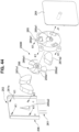
- the chair illustrated in FIG.44 , 45 and 46 is also configured such that the back 6 is arranged behind the seat, and the back has an operation mechanism 206M turning-movably supporting the load received from a seated person in a left-right direction in a front view, and when the load is applied, at least a part of guide parts 265a1, 266a1 (265a2, 266a2) of the operation mechanism is separated and the back moves freely, and when the applied load is removed, the operating position of the operation mechanism 206M automatically returns to the neutral position along the guide parts 265a1, 266a1 (265a2, 266a2) of the operation mechanism 206M.
- the seat is swingable in the left-right direction in a front view, and the back 6 performs a left-right turning operation separated from the seat.
- the operation mechanism 206M includes: the base part 264 fixed to or formed integrally with the back plate included in the backrest, and provided with the pressing tool 266 at the side of the back surface in an a protruding condition; the tilting part 265 disposed at a position adjacent to the base part 264, including the first guide part 265a1 recessed in a tapered shape at the back surface side of the tilting part, the center of the tilting part 265 having an opening in front-rear direction; and the back frame received pressure part 261a placed at the position facing the tilting part 265 interposing the pressing tool 266 and having the second guide part 265a2 that is recessed in a tapered shape on the front surface side.
- the pressing tool 266 is provided with the first convex guide part 266a1 and the second convex guide part 266a2 corresponding to the first guide part 265a1 and the second guide part 265a2 on the front surface side or the back surface side.
- the pressing tool 266 is fixed to the base part 264 through the opening of the tilting part 265, and the tilting part 265 is drawn and fixed by a screw to the back support part 261a at the upper end side of the back frame 261 configuring the back 206 as shown by arrow K1.
- the first elastic body 267a1 is interposed between the pressing tool 266 and the back frame received pressure part 261a
- the second elastic body 267a2 is interposed between the pressing tool 266 and the tilting part 265.
- the force in the direction where the guide part 266a1 of the pressing tool 266 is constantly fitted into by the elastic body 267a1, is applied to the guide part 265a1 of the tilting part 265, and the force in the direction where the guide part 266a2 of the pressing tool 266 is constantly fitted into by the elastic body 267a2, is applied to the guide part 265a2 of the back frame received pressure part 261a.
- the first guide part 266a1 and the second guide part 266a2 of the pressing tool 266 are provided with three protruding parts resembling propeller blade, and the first guide part 265a1 at the side of the tilting part 265 and the second guide part 265a2 at the side of the back frame received pressure part 261a that receive the protruding parts have a notch groove shape that receives a part of the three protruding parts.
- the guide parts 266a1, 266a2 have a polygonal line part being a convex and the guide parts 265a1, 265a2 are in a notch shape having a valley line part.
Landscapes
- Chairs For Special Purposes, Such As Reclining Chairs (AREA)
- Chairs Characterized By Structure (AREA)
- Chair Legs, Seat Parts, And Backrests (AREA)
Claims (8)
- Stuhl, wobei der Stuhl so konfiguriert ist, dass eine Lehne (6) hinter einem Sitz (5) angeordnet ist, und die Lehne (6) einen Funktionsmechanismus (6M) hat, der die Last, die von einer sitzenden Person aufgenommen wird, in einer Vorderansicht in einer Links-Rechts-Richtung drehbewegbar abstützt, und wenn die Last aufgebracht wird, zumindest ein Teil von Führungsteilen (65a, 66a) des Funktionsmechanismus (6M) getrennt wird und sich die Lehne (6) frei bewegt, und wenn die aufgebrachte Last entfernt wird, die Lehne (6) entlang der Führungsteile (65a, 66a) automatisch zu einer neutralen Position zurückkehrt,wobei der Funktionsmechanismus (6M) mit einem Basisteil (64) und einem Kippteil (65) versehen ist und eine Referenzposition aufweist, die der neutralen Position entspricht, ein Führungsteil (66a), der auf der Seite des Basisteils (64) eingestellt ist, und ein Führungsteil (65a), der auf der Seite des Kippteils (65) eingestellt ist, in Druckkontakt miteinander sind, um durch die Formen der Führungsteile (65a, 66a) geführt zu sein und bei der Referenzposition gestoppt zu sein, und wenn der Druckkontakt durch den aufgenommenen Druck von der sitzenden Person gelockert wird, der Basisteil (64) und der Kippteil (65) von der Referenzposition in Übereinstimmung mit dem Grad des aufgenommenen Drucks relativ verändert werden können,dadurch gekennzeichnet, dassein Führungsteil (65a) eine teilweise elliptische, mörserähnliche Form hat, die mindestens eine Tallinie (65ax) aufweist, und der andere Führungsteil (66a) eine gekrümmte Form hat, die mindestens eine Gratlinie (66ax) hat, die glatt in die Tallinie (65ax) eingepasst ist, und die Tallinie (65ax) und die Gratlinie (66ax) ineinander eingepasst werden können,sodass eine Reaktionskraft, mit der die Lehne (6) zu der neutralen Position zurückkehrt, in Übereinstimmung mit einem Betrag einer Drehbewegung sowohl zu der linken als auch der rechten Richtung größer wird.
- Stuhl nach Anspruch 1, wobei die Lehne (6) so konfiguriert ist, dass eine Rückenlehne (62) über den Funktionsmechanismus (6M) durch einen Lehnenrahmen (61) abgestützt ist, der Lehnenrahmen (61) an der Rückseite des Sitzes (5) aufgerichtet ist und die Rückenlehne (62) über den Funktionsmechanismus (6M) in einer Vorderansicht im Wesentlichen im Uhrzeigersinn oder gegen den Uhrzeigersinn drehbewegbar an dem Lehnenrahmen (61) befestigt ist.
- Stuhl nach Anspruch 2, wobei die Lehne (6) so konfiguriert ist, dass die Rückenlehne (62) über den Funktionsmechanismus (6M) durch den Lehnenrahmen (61) abgestützt ist, und die Rückenlehne (62) sich über den Funktionsmechanismus (6M), der einen elastischen Körper (67) hat, gegen eine elastische Reaktionskraft in Richtung der hinteren Richtung und der Drehrichtung bewegt.
- Stuhl nach Anspruch 2 oder 3, wobei die Rückenlehne (62) so konfiguriert ist, dass ein Drehbereich zu der Links-Rechts-Richtung in Übereinstimmung mit der Bewegung in der hinteren Richtung in Bezug auf den Lehnenrahmen (61) größer wird.
- Stuhl nach einem der Ansprüche 1 bis 4, wobei der Stuhl so konfiguriert ist, dass der Sitz (5) in einer Vorderansicht in der Links-Rechts-Richtung schwenkbar ist und die Lehne (6) eine Links-Rechts-Drehfunktion ausführt, die getrennt von dem Sitz (5) ist.
- Stuhl nach Anspruch 3, wobei der Stuhl so konfiguriert ist, dass der Druckkontakt der beiden Führungsteile (65a, 66a) durch den elastischen Körper (67) ausgebildet wird und der elastische Körper (67) durch den aufgenommenen Druck gepresst wird, wodurch der Führungsteil (65a) des Kippteils (65) und der Führungsteil (66a) des Basisteils (64) getrennt werden.
- Stuhl nach Anspruch 6, wobei der Funktionsmechanismus (6M) Folgendes aufweist: den Basisteil (64), der an der Rückenlehne (62) fixiert ist und mit dem elastischen Körper (67) auf der Rückflächenseite des Basisteils (64) versehen ist; den Kippteil (65), der an einer Position angeordnet ist, die neben dem Basisteil (64) ist, und einen Führungsteil (65a) aufweist, der bei der Rückflächenseite des Kippteils (65) in einer Verjüngungsform vertieft ist, wobei der Bodenteil des Führungsteils (65a) eine Öffnung hat; und ein Presswerkzeug (66), das einen Führungsteil (66a) aufweist, der eine konvexe Form hat, die dem Führungsteil (65a) des Kippteils (65) auf der Vorderflächenseite des Presswerkzeugs (66) entspricht, das Presswerkzeug (66) über die Öffnung des Kippteils (65) in einem Zustand, in dem der Führungsteil (66a) des Presswerkzeugs (66) in dem Führungsteil (65a) des Kippteils (65) eingepasst ist, an dem Basisteil (64) fixiert ist, und der Kippteil (65) an dem Teil des aufgenommenen Drucks befestigt ist, der an dem oberen Endteil des Lehnenrahmens (61) vorgesehen ist.
- Stuhl nach einem der Ansprüche 1 bis 7, wobei der Basisteil (64) und der Kippteil (65) mit Eingriffsteilen (64b, 65b) versehen sind, die konfiguriert sind, eine Relativbewegung des Basisteils (64) und des Kippteils (65) im Zusammenwirken mit den Führungsteilen (65a, 66a) zu regulieren.
Applications Claiming Priority (1)
| Application Number | Priority Date | Filing Date | Title |
|---|---|---|---|
| PCT/JP2017/022760 WO2018235175A1 (ja) | 2017-06-20 | 2017-06-20 | 椅子 |
Publications (3)
| Publication Number | Publication Date |
|---|---|
| EP3643205A1 EP3643205A1 (de) | 2020-04-29 |
| EP3643205A4 EP3643205A4 (de) | 2020-10-21 |
| EP3643205B1 true EP3643205B1 (de) | 2024-07-03 |
Family
ID=64736927
Family Applications (1)
| Application Number | Title | Priority Date | Filing Date |
|---|---|---|---|
| EP17914176.7A Active EP3643205B1 (de) | 2017-06-20 | 2017-06-20 | Stuhl |
Country Status (5)
| Country | Link |
|---|---|
| US (1) | US11103069B2 (de) |
| EP (1) | EP3643205B1 (de) |
| JP (1) | JP6896854B2 (de) |
| CN (1) | CN110650657B (de) |
| WO (1) | WO2018235175A1 (de) |
Families Citing this family (9)
| Publication number | Priority date | Publication date | Assignee | Title |
|---|---|---|---|---|
| US10881208B2 (en) * | 2016-02-23 | 2021-01-05 | Kokuyo Co., Ltd. | Chair and seat support mechanism |
| JP6735826B2 (ja) * | 2016-06-20 | 2020-08-05 | コクヨ株式会社 | 椅子及び座の支持機構 |
| EP3560386B1 (de) * | 2016-12-21 | 2023-03-22 | Kokuyo Co., Ltd. | Stuhl |
| JP6900478B2 (ja) * | 2017-06-20 | 2021-07-07 | コクヨ株式会社 | 椅子 |
| CA3113842C (en) * | 2018-10-19 | 2023-09-05 | Kokuyo Co., Ltd. | Chair |
| US11825949B2 (en) * | 2021-05-04 | 2023-11-28 | Michael David Collier | Ergonomic motion chair |
| US11229291B1 (en) * | 2021-05-04 | 2022-01-25 | Michael David Collier | Ergonomic motion chair |
| US12582232B2 (en) | 2021-05-04 | 2026-03-24 | Moovlab Inc. | Ergonomic motion chair |
| JP7484829B2 (ja) * | 2021-06-29 | 2024-05-16 | トヨタ自動車株式会社 | 椅子 |
Family Cites Families (17)
| Publication number | Priority date | Publication date | Assignee | Title |
|---|---|---|---|---|
| JPS46533Y1 (de) * | 1967-09-18 | 1971-01-09 | ||
| JPS5135312A (en) | 1974-09-20 | 1976-03-25 | Toray Industries | Jikienban no seizoho |
| JP3135597B2 (ja) | 1991-04-19 | 2001-02-19 | 株式会社日立製作所 | 表示制御装置の同期制御回路 |
| JP3555175B2 (ja) | 1994-05-27 | 2004-08-18 | アラコ株式会社 | 車両用シート |
| DE10048779A1 (de) * | 2000-09-29 | 2002-04-18 | Stoll Sedus Ag | Rückenlehne |
| GB0114581D0 (en) | 2001-06-14 | 2001-08-08 | White Adam | Twister seat |
| JP4735966B2 (ja) * | 2005-11-11 | 2011-07-27 | コクヨ株式会社 | 背支持装置、座支持装置及び椅子 |
| DE102006049677B4 (de) | 2006-10-18 | 2009-04-02 | Sedus Stoll Ag | Rückenlehne für einen Stuhl |
| JP3135597U (ja) | 2007-07-11 | 2007-09-20 | 舜 黄 | 椅子の背もたれ取り付け部材 |
| JP2009131357A (ja) * | 2007-11-29 | 2009-06-18 | Okamura Corp | 椅子 |
| JP5358821B2 (ja) * | 2008-01-16 | 2013-12-04 | コクヨ株式会社 | 椅子 |
| JP5514509B2 (ja) * | 2009-10-26 | 2014-06-04 | 株式会社イトーキ | ロッキング椅子 |
| EP2387913B1 (de) | 2010-05-21 | 2013-03-27 | Karl-Heinz Brändle | Vorrichtung zur Verbesserung der menschlichen Sitzhaltung |
| US10226127B2 (en) | 2010-11-25 | 2019-03-12 | Corechair Incorporated | Resistive support mechanism for a chair including user feedback |
| JP5863352B2 (ja) * | 2011-09-16 | 2016-02-16 | 株式会社イトーキ | 椅子 |
| CN105531147B (zh) | 2013-07-24 | 2017-11-03 | 丰田自动车株式会社 | 座椅 |
| DE102014103780B3 (de) | 2014-03-19 | 2015-06-18 | Wilkhahn Wilkening + Hahne Gmbh + Co. | Stuhl |
-
2017
- 2017-06-20 EP EP17914176.7A patent/EP3643205B1/de active Active
- 2017-06-20 WO PCT/JP2017/022760 patent/WO2018235175A1/ja not_active Ceased
- 2017-06-20 US US16/614,571 patent/US11103069B2/en active Active
- 2017-06-20 CN CN201780090957.1A patent/CN110650657B/zh active Active
- 2017-06-20 JP JP2019524758A patent/JP6896854B2/ja active Active
Also Published As
| Publication number | Publication date |
|---|---|
| JP6896854B2 (ja) | 2021-06-30 |
| EP3643205A1 (de) | 2020-04-29 |
| CN110650657B (zh) | 2023-06-27 |
| WO2018235175A1 (ja) | 2018-12-27 |
| JPWO2018235175A1 (ja) | 2020-04-23 |
| US11103069B2 (en) | 2021-08-31 |
| US20200085195A1 (en) | 2020-03-19 |
| EP3643205A4 (de) | 2020-10-21 |
| CN110650657A (zh) | 2020-01-03 |
Similar Documents
| Publication | Publication Date | Title |
|---|---|---|
| EP3643205B1 (de) | Stuhl | |
| EP3643203B1 (de) | Stuhl | |
| EP3643206B1 (de) | Stuhl | |
| KR20130111950A (ko) | 의자 | |
| US12108882B2 (en) | Chair having a movable seat | |
| EP3643204B1 (de) | Stuhl | |
| KR102287977B1 (ko) | 차량 시트의 암레스트 | |
| EP4159089B1 (de) | Stuhl | |
| JP6952509B2 (ja) | 椅子 | |
| JP2008080089A (ja) | 椅子 |
Legal Events
| Date | Code | Title | Description |
|---|---|---|---|
| STAA | Information on the status of an ep patent application or granted ep patent |
Free format text: STATUS: THE INTERNATIONAL PUBLICATION HAS BEEN MADE |
|
| PUAI | Public reference made under article 153(3) epc to a published international application that has entered the european phase |
Free format text: ORIGINAL CODE: 0009012 |
|
| STAA | Information on the status of an ep patent application or granted ep patent |
Free format text: STATUS: REQUEST FOR EXAMINATION WAS MADE |
|
| 17P | Request for examination filed |
Effective date: 20191119 |
|
| AK | Designated contracting states |
Kind code of ref document: A1 Designated state(s): AL AT BE BG CH CY CZ DE DK EE ES FI FR GB GR HR HU IE IS IT LI LT LU LV MC MK MT NL NO PL PT RO RS SE SI SK SM TR |
|
| AX | Request for extension of the european patent |
Extension state: BA ME |
|
| DAV | Request for validation of the european patent (deleted) | ||
| DAX | Request for extension of the european patent (deleted) | ||
| A4 | Supplementary search report drawn up and despatched |
Effective date: 20200922 |
|
| RIC1 | Information provided on ipc code assigned before grant |
Ipc: A47C 3/026 20060101ALI20200916BHEP Ipc: A47C 7/48 20060101AFI20200916BHEP |
|
| P01 | Opt-out of the competence of the unified patent court (upc) registered |
Effective date: 20230426 |
|
| STAA | Information on the status of an ep patent application or granted ep patent |
Free format text: STATUS: EXAMINATION IS IN PROGRESS |
|
| 17Q | First examination report despatched |
Effective date: 20230616 |
|
| GRAP | Despatch of communication of intention to grant a patent |
Free format text: ORIGINAL CODE: EPIDOSNIGR1 |
|
| STAA | Information on the status of an ep patent application or granted ep patent |
Free format text: STATUS: GRANT OF PATENT IS INTENDED |
|
| INTG | Intention to grant announced |
Effective date: 20240228 |
|
| GRAS | Grant fee paid |
Free format text: ORIGINAL CODE: EPIDOSNIGR3 |
|
| GRAA | (expected) grant |
Free format text: ORIGINAL CODE: 0009210 |
|
| STAA | Information on the status of an ep patent application or granted ep patent |
Free format text: STATUS: THE PATENT HAS BEEN GRANTED |
|
| AK | Designated contracting states |
Kind code of ref document: B1 Designated state(s): AL AT BE BG CH CY CZ DE DK EE ES FI FR GB GR HR HU IE IS IT LI LT LU LV MC MK MT NL NO PL PT RO RS SE SI SK SM TR |
|
| REG | Reference to a national code |
Ref country code: CH Ref legal event code: EP |
|
| REG | Reference to a national code |
Ref country code: DE Ref legal event code: R096 Ref document number: 602017083105 Country of ref document: DE |
|
| REG | Reference to a national code |
Ref country code: LT Ref legal event code: MG9D |
|
| REG | Reference to a national code |
Ref country code: NL Ref legal event code: MP Effective date: 20240703 |
|
| PG25 | Lapsed in a contracting state [announced via postgrant information from national office to epo] |
Ref country code: PT Free format text: LAPSE BECAUSE OF FAILURE TO SUBMIT A TRANSLATION OF THE DESCRIPTION OR TO PAY THE FEE WITHIN THE PRESCRIBED TIME-LIMIT Effective date: 20241104 |
|
| REG | Reference to a national code |
Ref country code: AT Ref legal event code: MK05 Ref document number: 1698889 Country of ref document: AT Kind code of ref document: T Effective date: 20240703 |
|
| PG25 | Lapsed in a contracting state [announced via postgrant information from national office to epo] |
Ref country code: NL Free format text: LAPSE BECAUSE OF FAILURE TO SUBMIT A TRANSLATION OF THE DESCRIPTION OR TO PAY THE FEE WITHIN THE PRESCRIBED TIME-LIMIT Effective date: 20240703 |
|
| PG25 | Lapsed in a contracting state [announced via postgrant information from national office to epo] |
Ref country code: PT Free format text: LAPSE BECAUSE OF FAILURE TO SUBMIT A TRANSLATION OF THE DESCRIPTION OR TO PAY THE FEE WITHIN THE PRESCRIBED TIME-LIMIT Effective date: 20241104 Ref country code: NL Free format text: LAPSE BECAUSE OF FAILURE TO SUBMIT A TRANSLATION OF THE DESCRIPTION OR TO PAY THE FEE WITHIN THE PRESCRIBED TIME-LIMIT Effective date: 20240703 |
|
| PG25 | Lapsed in a contracting state [announced via postgrant information from national office to epo] |
Ref country code: NO Free format text: LAPSE BECAUSE OF FAILURE TO SUBMIT A TRANSLATION OF THE DESCRIPTION OR TO PAY THE FEE WITHIN THE PRESCRIBED TIME-LIMIT Effective date: 20241003 |
|
| PG25 | Lapsed in a contracting state [announced via postgrant information from national office to epo] |
Ref country code: GR Free format text: LAPSE BECAUSE OF FAILURE TO SUBMIT A TRANSLATION OF THE DESCRIPTION OR TO PAY THE FEE WITHIN THE PRESCRIBED TIME-LIMIT Effective date: 20241004 Ref country code: FI Free format text: LAPSE BECAUSE OF FAILURE TO SUBMIT A TRANSLATION OF THE DESCRIPTION OR TO PAY THE FEE WITHIN THE PRESCRIBED TIME-LIMIT Effective date: 20240703 Ref country code: PL Free format text: LAPSE BECAUSE OF FAILURE TO SUBMIT A TRANSLATION OF THE DESCRIPTION OR TO PAY THE FEE WITHIN THE PRESCRIBED TIME-LIMIT Effective date: 20240703 |
|
| PG25 | Lapsed in a contracting state [announced via postgrant information from national office to epo] |
Ref country code: BG Free format text: LAPSE BECAUSE OF FAILURE TO SUBMIT A TRANSLATION OF THE DESCRIPTION OR TO PAY THE FEE WITHIN THE PRESCRIBED TIME-LIMIT Effective date: 20240703 |
|
| PG25 | Lapsed in a contracting state [announced via postgrant information from national office to epo] |
Ref country code: LV Free format text: LAPSE BECAUSE OF FAILURE TO SUBMIT A TRANSLATION OF THE DESCRIPTION OR TO PAY THE FEE WITHIN THE PRESCRIBED TIME-LIMIT Effective date: 20240703 |
|
| PG25 | Lapsed in a contracting state [announced via postgrant information from national office to epo] |
Ref country code: AT Free format text: LAPSE BECAUSE OF FAILURE TO SUBMIT A TRANSLATION OF THE DESCRIPTION OR TO PAY THE FEE WITHIN THE PRESCRIBED TIME-LIMIT Effective date: 20240703 Ref country code: IS Free format text: LAPSE BECAUSE OF FAILURE TO SUBMIT A TRANSLATION OF THE DESCRIPTION OR TO PAY THE FEE WITHIN THE PRESCRIBED TIME-LIMIT Effective date: 20241103 |
|
| PG25 | Lapsed in a contracting state [announced via postgrant information from national office to epo] |
Ref country code: HR Free format text: LAPSE BECAUSE OF FAILURE TO SUBMIT A TRANSLATION OF THE DESCRIPTION OR TO PAY THE FEE WITHIN THE PRESCRIBED TIME-LIMIT Effective date: 20240703 Ref country code: CZ Free format text: LAPSE BECAUSE OF FAILURE TO SUBMIT A TRANSLATION OF THE DESCRIPTION OR TO PAY THE FEE WITHIN THE PRESCRIBED TIME-LIMIT Effective date: 20240703 |
|
| PG25 | Lapsed in a contracting state [announced via postgrant information from national office to epo] |
Ref country code: RS Free format text: LAPSE BECAUSE OF FAILURE TO SUBMIT A TRANSLATION OF THE DESCRIPTION OR TO PAY THE FEE WITHIN THE PRESCRIBED TIME-LIMIT Effective date: 20241003 Ref country code: ES Free format text: LAPSE BECAUSE OF FAILURE TO SUBMIT A TRANSLATION OF THE DESCRIPTION OR TO PAY THE FEE WITHIN THE PRESCRIBED TIME-LIMIT Effective date: 20240703 |
|
| PG25 | Lapsed in a contracting state [announced via postgrant information from national office to epo] |
Ref country code: RS Free format text: LAPSE BECAUSE OF FAILURE TO SUBMIT A TRANSLATION OF THE DESCRIPTION OR TO PAY THE FEE WITHIN THE PRESCRIBED TIME-LIMIT Effective date: 20241003 Ref country code: PL Free format text: LAPSE BECAUSE OF FAILURE TO SUBMIT A TRANSLATION OF THE DESCRIPTION OR TO PAY THE FEE WITHIN THE PRESCRIBED TIME-LIMIT Effective date: 20240703 Ref country code: NO Free format text: LAPSE BECAUSE OF FAILURE TO SUBMIT A TRANSLATION OF THE DESCRIPTION OR TO PAY THE FEE WITHIN THE PRESCRIBED TIME-LIMIT Effective date: 20241003 Ref country code: LV Free format text: LAPSE BECAUSE OF FAILURE TO SUBMIT A TRANSLATION OF THE DESCRIPTION OR TO PAY THE FEE WITHIN THE PRESCRIBED TIME-LIMIT Effective date: 20240703 Ref country code: IS Free format text: LAPSE BECAUSE OF FAILURE TO SUBMIT A TRANSLATION OF THE DESCRIPTION OR TO PAY THE FEE WITHIN THE PRESCRIBED TIME-LIMIT Effective date: 20241103 Ref country code: HR Free format text: LAPSE BECAUSE OF FAILURE TO SUBMIT A TRANSLATION OF THE DESCRIPTION OR TO PAY THE FEE WITHIN THE PRESCRIBED TIME-LIMIT Effective date: 20240703 Ref country code: GR Free format text: LAPSE BECAUSE OF FAILURE TO SUBMIT A TRANSLATION OF THE DESCRIPTION OR TO PAY THE FEE WITHIN THE PRESCRIBED TIME-LIMIT Effective date: 20241004 Ref country code: FI Free format text: LAPSE BECAUSE OF FAILURE TO SUBMIT A TRANSLATION OF THE DESCRIPTION OR TO PAY THE FEE WITHIN THE PRESCRIBED TIME-LIMIT Effective date: 20240703 Ref country code: ES Free format text: LAPSE BECAUSE OF FAILURE TO SUBMIT A TRANSLATION OF THE DESCRIPTION OR TO PAY THE FEE WITHIN THE PRESCRIBED TIME-LIMIT Effective date: 20240703 Ref country code: CZ Free format text: LAPSE BECAUSE OF FAILURE TO SUBMIT A TRANSLATION OF THE DESCRIPTION OR TO PAY THE FEE WITHIN THE PRESCRIBED TIME-LIMIT Effective date: 20240703 Ref country code: BG Free format text: LAPSE BECAUSE OF FAILURE TO SUBMIT A TRANSLATION OF THE DESCRIPTION OR TO PAY THE FEE WITHIN THE PRESCRIBED TIME-LIMIT Effective date: 20240703 Ref country code: AT Free format text: LAPSE BECAUSE OF FAILURE TO SUBMIT A TRANSLATION OF THE DESCRIPTION OR TO PAY THE FEE WITHIN THE PRESCRIBED TIME-LIMIT Effective date: 20240703 |
|
| REG | Reference to a national code |
Ref country code: DE Ref legal event code: R097 Ref document number: 602017083105 Country of ref document: DE |
|
| PG25 | Lapsed in a contracting state [announced via postgrant information from national office to epo] |
Ref country code: DK Free format text: LAPSE BECAUSE OF FAILURE TO SUBMIT A TRANSLATION OF THE DESCRIPTION OR TO PAY THE FEE WITHIN THE PRESCRIBED TIME-LIMIT Effective date: 20240703 Ref country code: RO Free format text: LAPSE BECAUSE OF FAILURE TO SUBMIT A TRANSLATION OF THE DESCRIPTION OR TO PAY THE FEE WITHIN THE PRESCRIBED TIME-LIMIT Effective date: 20240703 Ref country code: SM Free format text: LAPSE BECAUSE OF FAILURE TO SUBMIT A TRANSLATION OF THE DESCRIPTION OR TO PAY THE FEE WITHIN THE PRESCRIBED TIME-LIMIT Effective date: 20240703 |
|
| PG25 | Lapsed in a contracting state [announced via postgrant information from national office to epo] |
Ref country code: EE Free format text: LAPSE BECAUSE OF FAILURE TO SUBMIT A TRANSLATION OF THE DESCRIPTION OR TO PAY THE FEE WITHIN THE PRESCRIBED TIME-LIMIT Effective date: 20240703 |
|
| PG25 | Lapsed in a contracting state [announced via postgrant information from national office to epo] |
Ref country code: IT Free format text: LAPSE BECAUSE OF FAILURE TO SUBMIT A TRANSLATION OF THE DESCRIPTION OR TO PAY THE FEE WITHIN THE PRESCRIBED TIME-LIMIT Effective date: 20240703 Ref country code: SK Free format text: LAPSE BECAUSE OF FAILURE TO SUBMIT A TRANSLATION OF THE DESCRIPTION OR TO PAY THE FEE WITHIN THE PRESCRIBED TIME-LIMIT Effective date: 20240703 |
|
| PLBE | No opposition filed within time limit |
Free format text: ORIGINAL CODE: 0009261 |
|
| STAA | Information on the status of an ep patent application or granted ep patent |
Free format text: STATUS: NO OPPOSITION FILED WITHIN TIME LIMIT |
|
| 26N | No opposition filed |
Effective date: 20250404 |
|
| PGFP | Annual fee paid to national office [announced via postgrant information from national office to epo] |
Ref country code: DE Payment date: 20250429 Year of fee payment: 9 |
|
| PGFP | Annual fee paid to national office [announced via postgrant information from national office to epo] |
Ref country code: GB Payment date: 20250501 Year of fee payment: 9 |
|
| PG25 | Lapsed in a contracting state [announced via postgrant information from national office to epo] |
Ref country code: SE Free format text: LAPSE BECAUSE OF FAILURE TO SUBMIT A TRANSLATION OF THE DESCRIPTION OR TO PAY THE FEE WITHIN THE PRESCRIBED TIME-LIMIT Effective date: 20240703 |
|
| REG | Reference to a national code |
Ref country code: CH Ref legal event code: H13 Free format text: ST27 STATUS EVENT CODE: U-0-0-H10-H13 (AS PROVIDED BY THE NATIONAL OFFICE) Effective date: 20260127 |
|
| PG25 | Lapsed in a contracting state [announced via postgrant information from national office to epo] |
Ref country code: MC Free format text: LAPSE BECAUSE OF FAILURE TO SUBMIT A TRANSLATION OF THE DESCRIPTION OR TO PAY THE FEE WITHIN THE PRESCRIBED TIME-LIMIT Effective date: 20240703 |
|
| PG25 | Lapsed in a contracting state [announced via postgrant information from national office to epo] |
Ref country code: LU Free format text: LAPSE BECAUSE OF NON-PAYMENT OF DUE FEES Effective date: 20250620 |
|
| REG | Reference to a national code |
Ref country code: BE Ref legal event code: MM Effective date: 20250630 |
|
| PG25 | Lapsed in a contracting state [announced via postgrant information from national office to epo] |
Ref country code: IE Free format text: LAPSE BECAUSE OF NON-PAYMENT OF DUE FEES Effective date: 20250620 |
|
| PG25 | Lapsed in a contracting state [announced via postgrant information from national office to epo] |
Ref country code: BE Free format text: LAPSE BECAUSE OF NON-PAYMENT OF DUE FEES Effective date: 20250630 |
|
| PG25 | Lapsed in a contracting state [announced via postgrant information from national office to epo] |
Ref country code: FR Free format text: LAPSE BECAUSE OF NON-PAYMENT OF DUE FEES Effective date: 20250630 |
|
| PG25 | Lapsed in a contracting state [announced via postgrant information from national office to epo] |
Ref country code: CH Free format text: LAPSE BECAUSE OF NON-PAYMENT OF DUE FEES Effective date: 20250630 |