EP3643338A2 - Système d'aspiration et d'irrigation actionné par dépression - Google Patents
Système d'aspiration et d'irrigation actionné par dépression Download PDFInfo
- Publication number
- EP3643338A2 EP3643338A2 EP19205465.8A EP19205465A EP3643338A2 EP 3643338 A2 EP3643338 A2 EP 3643338A2 EP 19205465 A EP19205465 A EP 19205465A EP 3643338 A2 EP3643338 A2 EP 3643338A2
- Authority
- EP
- European Patent Office
- Prior art keywords
- vacuum
- fluid
- bore
- valve
- suction
- Prior art date
- Legal status (The legal status is an assumption and is not a legal conclusion. Google has not performed a legal analysis and makes no representation as to the accuracy of the status listed.)
- Withdrawn
Links
- 239000012530 fluid Substances 0.000 claims abstract description 260
- 230000002262 irrigation Effects 0.000 claims abstract description 160
- 238000003973 irrigation Methods 0.000 claims abstract description 160
- 230000007246 mechanism Effects 0.000 claims description 31
- 230000006835 compression Effects 0.000 claims description 16
- 238000007906 compression Methods 0.000 claims description 16
- 230000000712 assembly Effects 0.000 description 17
- 238000000429 assembly Methods 0.000 description 17
- 230000008859 change Effects 0.000 description 4
- 239000003302 ferromagnetic material Substances 0.000 description 3
- 239000000463 material Substances 0.000 description 3
- 230000008901 benefit Effects 0.000 description 2
- 239000008280 blood Substances 0.000 description 2
- 210000004369 blood Anatomy 0.000 description 2
- FAPWRFPIFSIZLT-UHFFFAOYSA-M Sodium chloride Chemical compound [Na+].[Cl-] FAPWRFPIFSIZLT-UHFFFAOYSA-M 0.000 description 1
- 238000013459 approach Methods 0.000 description 1
- 238000010276 construction Methods 0.000 description 1
- 230000008602 contraction Effects 0.000 description 1
- 230000008878 coupling Effects 0.000 description 1
- 238000010168 coupling process Methods 0.000 description 1
- 238000005859 coupling reaction Methods 0.000 description 1
- 230000001934 delay Effects 0.000 description 1
- 238000000034 method Methods 0.000 description 1
- 230000000717 retained effect Effects 0.000 description 1
- 239000011780 sodium chloride Substances 0.000 description 1
- -1 tissue Substances 0.000 description 1
- 230000007704 transition Effects 0.000 description 1
- 238000012800 visualization Methods 0.000 description 1
Images







Classifications
-
- F—MECHANICAL ENGINEERING; LIGHTING; HEATING; WEAPONS; BLASTING
- F04—POSITIVE - DISPLACEMENT MACHINES FOR LIQUIDS; PUMPS FOR LIQUIDS OR ELASTIC FLUIDS
- F04B—POSITIVE-DISPLACEMENT MACHINES FOR LIQUIDS; PUMPS
- F04B43/00—Machines, pumps, or pumping installations having flexible working members
- F04B43/02—Machines, pumps, or pumping installations having flexible working members having plate-like flexible members, e.g. diaphragms
- F04B43/06—Pumps having fluid drive
- F04B43/073—Pumps having fluid drive the actuating fluid being controlled by at least one valve
- F04B43/0736—Pumps having fluid drive the actuating fluid being controlled by at least one valve with two or more pumping chambers in parallel
-
- A—HUMAN NECESSITIES
- A61—MEDICAL OR VETERINARY SCIENCE; HYGIENE
- A61M—DEVICES FOR INTRODUCING MEDIA INTO, OR ONTO, THE BODY; DEVICES FOR TRANSDUCING BODY MEDIA OR FOR TAKING MEDIA FROM THE BODY; DEVICES FOR PRODUCING OR ENDING SLEEP OR STUPOR
- A61M1/00—Suction or pumping devices for medical purposes; Devices for carrying-off, for treatment of, or for carrying-over, body-liquids; Drainage systems
- A61M1/71—Suction drainage systems
- A61M1/74—Suction control
- A61M1/741—Suction control with means for varying suction manually
-
- A—HUMAN NECESSITIES
- A61—MEDICAL OR VETERINARY SCIENCE; HYGIENE
- A61M—DEVICES FOR INTRODUCING MEDIA INTO, OR ONTO, THE BODY; DEVICES FOR TRANSDUCING BODY MEDIA OR FOR TAKING MEDIA FROM THE BODY; DEVICES FOR PRODUCING OR ENDING SLEEP OR STUPOR
- A61M1/00—Suction or pumping devices for medical purposes; Devices for carrying-off, for treatment of, or for carrying-over, body-liquids; Drainage systems
- A61M1/71—Suction drainage systems
- A61M1/74—Suction control
- A61M1/743—Suction control by changing the cross-section of the line, e.g. flow regulating valves
-
- A—HUMAN NECESSITIES
- A61—MEDICAL OR VETERINARY SCIENCE; HYGIENE
- A61M—DEVICES FOR INTRODUCING MEDIA INTO, OR ONTO, THE BODY; DEVICES FOR TRANSDUCING BODY MEDIA OR FOR TAKING MEDIA FROM THE BODY; DEVICES FOR PRODUCING OR ENDING SLEEP OR STUPOR
- A61M1/00—Suction or pumping devices for medical purposes; Devices for carrying-off, for treatment of, or for carrying-over, body-liquids; Drainage systems
- A61M1/71—Suction drainage systems
- A61M1/77—Suction-irrigation systems
-
- A—HUMAN NECESSITIES
- A61—MEDICAL OR VETERINARY SCIENCE; HYGIENE
- A61M—DEVICES FOR INTRODUCING MEDIA INTO, OR ONTO, THE BODY; DEVICES FOR TRANSDUCING BODY MEDIA OR FOR TAKING MEDIA FROM THE BODY; DEVICES FOR PRODUCING OR ENDING SLEEP OR STUPOR
- A61M1/00—Suction or pumping devices for medical purposes; Devices for carrying-off, for treatment of, or for carrying-over, body-liquids; Drainage systems
- A61M1/80—Suction pumps
- A61M1/82—Membrane pumps, e.g. bulbs
-
- A—HUMAN NECESSITIES
- A61—MEDICAL OR VETERINARY SCIENCE; HYGIENE
- A61M—DEVICES FOR INTRODUCING MEDIA INTO, OR ONTO, THE BODY; DEVICES FOR TRANSDUCING BODY MEDIA OR FOR TAKING MEDIA FROM THE BODY; DEVICES FOR PRODUCING OR ENDING SLEEP OR STUPOR
- A61M3/00—Medical syringes, e.g. enemata; Irrigators
- A61M3/02—Enemata; Irrigators
- A61M3/0233—Enemata; Irrigators characterised by liquid supply means, e.g. from pressurised reservoirs
- A61M3/0237—Enemata; Irrigators characterised by liquid supply means, e.g. from pressurised reservoirs the pressure being generated in the reservoir, e.g. by gas generating tablets
-
- A—HUMAN NECESSITIES
- A61—MEDICAL OR VETERINARY SCIENCE; HYGIENE
- A61M—DEVICES FOR INTRODUCING MEDIA INTO, OR ONTO, THE BODY; DEVICES FOR TRANSDUCING BODY MEDIA OR FOR TAKING MEDIA FROM THE BODY; DEVICES FOR PRODUCING OR ENDING SLEEP OR STUPOR
- A61M3/00—Medical syringes, e.g. enemata; Irrigators
- A61M3/02—Enemata; Irrigators
- A61M3/0233—Enemata; Irrigators characterised by liquid supply means, e.g. from pressurised reservoirs
- A61M3/0254—Enemata; Irrigators characterised by liquid supply means, e.g. from pressurised reservoirs the liquid being pumped
-
- A—HUMAN NECESSITIES
- A61—MEDICAL OR VETERINARY SCIENCE; HYGIENE
- A61M—DEVICES FOR INTRODUCING MEDIA INTO, OR ONTO, THE BODY; DEVICES FOR TRANSDUCING BODY MEDIA OR FOR TAKING MEDIA FROM THE BODY; DEVICES FOR PRODUCING OR ENDING SLEEP OR STUPOR
- A61M39/00—Tubes, tube connectors, tube couplings, valves, access sites or the like, specially adapted for medical use
- A61M39/22—Valves or arrangement of valves
- A61M39/227—Valves actuated by a secondary fluid, e.g. hydraulically or pneumatically actuated valves
-
- F—MECHANICAL ENGINEERING; LIGHTING; HEATING; WEAPONS; BLASTING
- F04—POSITIVE - DISPLACEMENT MACHINES FOR LIQUIDS; PUMPS FOR LIQUIDS OR ELASTIC FLUIDS
- F04B—POSITIVE-DISPLACEMENT MACHINES FOR LIQUIDS; PUMPS
- F04B43/00—Machines, pumps, or pumping installations having flexible working members
- F04B43/0009—Special features
- F04B43/0054—Special features particularities of the flexible members
-
- F—MECHANICAL ENGINEERING; LIGHTING; HEATING; WEAPONS; BLASTING
- F04—POSITIVE - DISPLACEMENT MACHINES FOR LIQUIDS; PUMPS FOR LIQUIDS OR ELASTIC FLUIDS
- F04B—POSITIVE-DISPLACEMENT MACHINES FOR LIQUIDS; PUMPS
- F04B43/00—Machines, pumps, or pumping installations having flexible working members
- F04B43/02—Machines, pumps, or pumping installations having flexible working members having plate-like flexible members, e.g. diaphragms
- F04B43/06—Pumps having fluid drive
-
- A—HUMAN NECESSITIES
- A61—MEDICAL OR VETERINARY SCIENCE; HYGIENE
- A61B—DIAGNOSIS; SURGERY; IDENTIFICATION
- A61B2217/00—General characteristics of surgical instruments
- A61B2217/002—Auxiliary appliance
- A61B2217/005—Auxiliary appliance with suction drainage system
-
- A—HUMAN NECESSITIES
- A61—MEDICAL OR VETERINARY SCIENCE; HYGIENE
- A61B—DIAGNOSIS; SURGERY; IDENTIFICATION
- A61B2217/00—General characteristics of surgical instruments
- A61B2217/002—Auxiliary appliance
- A61B2217/007—Auxiliary appliance with irrigation system
Definitions
- the disclosure is directed to a suction and irrigation system and, more particularly, to a vacuum assisted suction and irrigation system.
- Suction and irrigation systems that include a surgical instrument to provide both suction and irrigation to a surgical site are well known.
- such systems include a source of vacuum that is coupled to the surgical instrument to provide suction and an electric, e.g., battery powered pump to deliver irrigation fluid to the surgical instrument.
- an electric e.g., battery powered pump to deliver irrigation fluid to the surgical instrument.
- two types of power sources are required to use the surgical instrument.
- the first piston is coupled to the second piston by a piston shaft such that the first and second pistons are movable in unison between first and second end stroke positions.
- the body defines a first bore that communicates the first vacuum cavity with the atmosphere channel, a second bore that communicates the second vacuum cavity with the atmosphere channel, a third bore that communicates the first vacuum cavity with the vacuum chamber, and a fourth bore that communicates the second vacuum cavity with the vacuum chamber.
- the atmosphere valve assembly includes a first valve member and a second valve member. The atmosphere valve assembly is movable between a first end stroke position in which the first valve member seals the first bore and the second bore is unsealed, and a second end stroke position in which the second seal member seals the second bore and the first bore is unsealed.
- the first valve member is coupled to the second valve member by a first valve shaft.
- the vacuum valve assembly includes a third valve member and a fourth valve member. The vacuum valve assembly is movable between a first end stroke position in which the third valve member seals the third bore and the fourth bore is unsealed, and a second end stroke position in which the fourth seal member seals the fourth bore and the third bore is unsealed.
- the third valve member is coupled to the fourth valve member by a second valve shaft.
- the first frame member interconnects first ends of the first and second valve shafts and the second frame member interconnects second ends of the first and second valve shafts.
- the fluid pump is a diaphragm type pump.
- the first diaphragm supports a first piston or shaft holder and the second diaphragm supports a second piston or shaft holder.
- the fluid pump includes a vacuum chamber and an atmosphere channel, wherein the vacuum chamber communicates with the vacuum source and the atmosphere channel communicates with atmosphere.
- the fluid pump includes a atmosphere valve assembly, a first bore communicating the first vacuum cavity with the atmosphere channel, and a second bore communicating the second vacuum cavity with the atmosphere channel.
- the fluid pump includes a vacuum valve assembly, a third bore communicating the first vacuum cavity with the vacuum chamber, and a fourth bore communicating the second vacuum cavity with the vacuum chamber.
- the vacuum valve assembly includes a third valve member and a fourth valve member and is movable between a first position in which the third valve member seals the third bore and the fourth bore is unsealed, and a second position in which the fourth seal member seals the fourth bore and the third bore is unsealed.
- the first valve member is coupled to the second valve member by a first valve shaft and the third valve member is coupled to the fourth valve member by a second valve shaft.
- the irrigation fluid supply includes a compressible pouch.
- the fluid pump includes a base member and a compression member having a first end pivotally coupled to the base member.
- the compressible pouch is positioned between the base member and the compression member.
- the fluid pump includes a first frame member and a second frame member, wherein the first frame member interconnects first ends of the first and second valve shafts and the second frame member interconnects second ends of the first and second valve shafts.
- an inner magnet is supported on the body adjacent each of the first and second vacuum cavities of the first and second pump chambers, wherein each of the inner magnets is positioned to attract a respective one of the first and second frame members to urge the atmosphere valve assembly and the vacuum valve assembly towards one of their end stroke positions.
- each of the first and second pistons supports a biasing mechanism, wherein the biasing mechanism is positioned to engage a respective one of the first and second frame members to urge the first and second valve shafts to one of their end stroke positions and delay transitioning of the atmosphere valve assembly and the vacuum valve assembly from one of their first and second end stroke positions to the other of their end stroke positions.
- the first and second biasing mechanisms each include an annular spring and an annular plate, wherein the annular spring is compressible and expandable to maintain the annular plate in engagement with a respective one of the frame members to maintain the atmosphere valve assembly and the vacuum valve assembly in its end stroke position as the piston shaft changes direction.
- an outer magnet is supported on the body adjacent each of the first and second fluid cavities of the first and second pump chambers, wherein the outer magnets are positioned to draw a respective one of the first and second pistons towards one of its end stroke positions when the fluid pump is stopped to facilitate restart of the fluid pump.
- a fluid pump in another aspect of the disclosure, includes a body, a first diaphragm, a second diaphragm, a first piston, a second piston, an atmosphere valve assembly, a vacuum valve assembly, and outer magnets.
- the body defines a first pump chamber, a second pump chamber, a vacuum chamber, and an atmosphere channel.
- the vacuum chamber communicates with the vacuum source and the atmosphere channel communicates with atmosphere.
- the first diaphragm divides the first pump chamber into a first vacuum cavity and a first fluid cavity and the second diaphragm divides the second pump chamber into a second vacuum cavity and a second fluid cavity.
- the first piston is supported by the first diaphragm and the second piston is supported by the second diaphragm.
- the first piston is coupled to the second piston by a piston shaft such that the first and second pistons are movable in unison between first and second end stroke positions.
- the body defines a first bore that communicates the first vacuum cavity with the atmosphere channel, a second bore that communicates the second vacuum cavity with the atmosphere channel, a third bore that communicates the first vacuum cavity with the vacuum chamber, and a fourth bore that communicates the second vacuum cavity with the vacuum chamber.
- the atmosphere valve assembly includes a first valve member and a second valve member. The atmosphere valve assembly is movable between a first end stroke position in which the first valve member seals the first bore and the second bore is unsealed, and a second end stroke position in which the second seal member seals the second bore and the first bore is unsealed.
- the first valve member is coupled to the second valve member by a first valve shaft.
- the vacuum valve assembly includes a third valve member and a fourth valve member. The vacuum valve assembly is movable between a first end stroke position in which the third valve member seals the third bore and the fourth bore is unsealed, and a second end stroke position in which the fourth seal member seals the fourth bore and the third bore is unsealed.
- the third valve member is coupled to the fourth valve member by a second valve shaft.
- the outer magnets are supported on the body adjacent each of the first and second fluid cavities of the first and second pump chambers and are positioned to draw a respective one of the first and second pistons towards its end stroke position when the fluid pump is stopped to facilitate restart of the fluid pump.
- proximal is used generally to refer to that portion of the device that is closer to a clinician
- distal is used generally to refer to that portion of the device that is farther from the clinician
- clinician is used generally to refer to medical personnel including doctors, nurses, and support personnel.
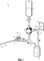
- FIG. 1 An exemplary aspect of the disclosed vacuum assisted suction and irrigation system is shown generally in FIG. 1 as system 10.
- the system 10 includes an irrigation fluid supply 12, a vacuum source 14, a fluid pump 16, a suction container 18, and a suction and irrigation wand 22.
- the components of the device 10 are fluidly coupled to each other with fluid conduits 24-32 as described in further detail below.
- the suction and irrigation wand 22 includes a proximal body portion 34 and a distal body portion 40.
- the proximal body portion 34 supports a suction valve 36 and an irrigation valve 38.
- the distal body portion 40 defines a fluid channel 42 for receiving or dispensing fluid depending on which valve of the suction valve 36 and irrigation valve 38 is actuated.
- the proximal body portion 34 of the suction and irrigation wand 22 is connected to the irrigation fluid supply 12 by the fluid conduits 24 and 26 such that upon actuation of the irrigation valve 38, irrigation fluid is delivered to the fluid channel 42 of the distal body portion 40 of the suction and irrigation wand 22.
- the proximal body portion 34 of the suction and irrigation wand 22 is connected to the vacuum source 14 by the fluid conduits 30 and 32 via the suction container 18.
- a vacuum is created in the fluid channel 42 of the distal body portion 40 of the suction and irrigation wand 22 to draw fluid into the fluid channel 42.
- the suction and irrigation wand 22 communicates with the suction container 18 via the fluid conduit 32 and the suction container 18 communicates with the vacuum source 14 via the fluid conduit 30. As such, a vacuum is maintained within the suction container 18 by the vacuum source 14.
- the suction valve 36 is actuated, the fluid channel 42 in the suction and irrigation wand 22 is communicates with the suction container 20 to create a vacuum within the fluid channel 42. All materials drawn into the channel 42 of the suction and irrigation wand 22, such as blood, tissue, saline, etc., are delivered to and collected within the suction container 20.
- the irrigation supply 12 is coupled to the fluid pump 16 by fluid conduit 24 and the fluid pump 16 is coupled to the suction and irrigation wand 22 by the fluid conduit 26.
- the irrigation valve 38 When the irrigation valve 38 is actuated, fluid from within the irrigation fluid supply 12 is delivered to the suction and irrigation wand 22 via the fluid pump 16.
- the irrigation fluid supply 12 can be connected directly to the suction and irrigation wand 22 and alternative means can be provided to pressurize the irrigation fluid supply 12.
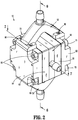
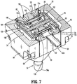
- FIGS. 2-7 illustrate exemplary aspects of the fluid pump 16.
- the fluid pump 16 is a diaphragm type pump and includes a housing 50, a fluid inlet manifold 52, and a fluid outlet manifold 54.
- the housing 50 includes a central housing portion 56, a first pump chamber body portion 58, a second pump chamber body portion 60, a first pump chamber cover 62, and a second pump chamber cover 64.
- the fluid inlet manifold 52 is coupled to the irrigation fluid supply 12 via the fluid conduit 24 ( FIG. 1 ) and the fluid outlet manifold 54 is coupled to the suction and irrigation wand 22 via fluid conduit 26.
- the fluid inlet and outlet manifolds 52, 54 can be secured to the housing 50 using screws 66 or the like.
- the different components of the housing 50 can be secured together using nuts 68 and bolts 70 or the like.
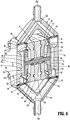
- the fluid pump 16 includes two pump chambers 72, 74 ( FIG. 6 ).
- the first pump chamber 72 is defined between the first pump chamber body portion 58 and the first pump chamber cover portion 62.
- the second pump chamber 74 is defined between the second pump chamber body portion 60 and the second pump chamber cover portion 64.
- the first pump chamber 72 defines an inlet opening 76 ( FIG. 6 ) and a fluid outlet opening 78 ( FIG. 6 ). Each of the inlet and outlet openings 76, 78, is sealed by a respective check valve 80, 82, respectively.
- the second pump chamber 74 defines an inlet opening 84 and a fluid outlet opening 86 that are sealed by check valves 88, 90, respectively.
- the first pump chamber 72 is divided into a fluid cavity 72a and a vacuum cavity 72b by a diaphragm 92 ( FIG. 6 ).
- the diaphragm 92 includes an outer flexible portion 94 of reduced thickness and a more rigid central portion 96 that is configured to support a first piston 98.
- the second pump chamber 74 is divided into a fluid cavity 74a and a vacuum cavity 74b by a diaphragm 100 ( FIG. 6 ).
- the diaphragm 100 includes an outer flexible portion 102 of reduced thickness and a more rigid central portion 104 that is configured to support a second piston 106.
- the central housing portion 56 and the body portions 58, 60 of the housing 50 define a bore 108 ( FIG. 6 ) that that extends between the first and second pump chambers 72, 74, respectively.
- the bore 108 receives a bushing 110 and a piston shaft 112 that has a first end secured to the first piston 98 and a second end secured to the second piston 106.
- a seal 114 is supported about the piston shaft 112 at each end of the bushing 110 to provide a seal about the piston shaft 112 within the bore 108 at each end piston shaft 112.
- the inlet manifold 52 defines a bifurcated or Y-shaped fluid channel 120 having an inlet 52a that communicates with the inlet openings 76, 84 of the first and second pump chambers 72, 74, respectively.
- the outlet manifold 54 defines a Y-shaped fluid channel 122 that has an outlet 54a that communicates with the outlet openings 78, 86 of the first and second pump chambers 72, 74, respectively.
- the check valves 80, 82, 88 and 90 are configured to allow fluid to flow in one direction, i.e., into the first and second pump chambers 72, 74 from the inlet manifold 52 and out of the first and second pump chambers 72, 74 through the outlet manifold 54.
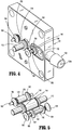
- FIGS. 3-7 illustrate the central housing portion 56 and the first and second pump chamber body portions 58, 60 of the housing 50 of the fluid pump 16 which define a vacuum chamber 130 and a vacuum port 132 ( FIG. 7 ).
- the vacuum port 132 defines a channel 132a that communicates with the vacuum chamber 130.
- the first pump chamber body portion 58 defines a bore 134 ( FIG. 8 ) that communicates the vacuum chamber 130 with the vacuum cavity 72b of the first pump chamber 72.
- the second pump chamber body portion 60 defines a bore 136 that communicates the vacuum chamber 130 with the vacuum cavity 74b of the second pump chamber 74.
- the bores 134, 136 are positioned to facilitate application of a vacuum to the vacuum cavities 72b, 74b of the first and second pump chambers 72, 74 of the fluid pump 16 to control movement of the diaphragms 94, 100 within the first and second pump chambers 72, 74 as described in more detail below.
- the central housing portion 56 ( FIG. 4 ) of the housing 50 of the fluid pump 16 defines a bore 140 that receives a vacuum valve assembly 150.
- the vacuum valve assembly 150 includes a bushing 152, first and second seal members 154, a valve shaft 156, and valve members 158, 160 that are positioned to alternately seal the bores 134, 136 of the first and second pump chamber body portions 58, 60 ( FIG. 5 ).
- the central housing portion 56 of the housing 50 of the fluid pump 16 also defines a bore 170 ( FIG. 4 ) that receives an atmosphere valve assembly 174.
- the first and second pump chamber body portions 58, 60 define bores 186, 188.
- the atmosphere valve assembly 174 includes a bushing 176, a valve shaft 180, and valve members 182, 184 that are positioned to alternately seal the bores 186, 188.
- the bores 186, 188 connect the vacuum cavities 72b, 74b of the first and second pump chambers 72, 74 with atmosphere channels 190 ( FIG. 7 ) formed in the first and second pump chamber body portions 58, 60.
- the valve shaft 180 connects the valve member 182 to the valve member 184 and is movable within the bushing 176 between a first position in which the valve member 182 seals the bore 186 of the first pump chamber body portion 58 while the bore 188 of the second pump chamber body portion 60 remains unsealed and a second position in which the valve member 184 seals the bore 188 of the second pump chamber body portion 60 while the bore 186 of the first pump chamber body portion 58 remains unsealed.
- FIGS. 8 and 9 illustrate the valve shaft 180 of the atmosphere valve assembly 174 and the valve member 160 of the vacuum valve assembly 150 which are positioned to be engaged by the diaphragm 104 within the second pump chamber 74 when the diaphragm 104 moves in the direction indicated by arrows "A" to a position to collapse the vacuum cavity 74b of the second pump chamber 74.
- the diaphragm 104 moves to the position shown in FIG.
- valve member 184 of the atmosphere valve assembly 174 moves to a position to unseal the bore 188 connecting the vacuum cavity 74b of the second pump chamber 74 to the atmosphere channels 190 and the valve member182 moves to a position to seal the bore 186 connecting the vacuum cavity 72b of the first pump chamber 72 to the atmosphere channels 190.
- diaphragm 104 moves to the position shown in FIG.
- the valve shaft 156 of the vacuum valve assembly 150 moves in the direction of arrows "A" to move the valve member 160 of the vacuum valve assembly150 to a position to seal the bore 136 connecting the vacuum chamber 130 to the vacuum cavity 74b and the valve member 158 moves to a position to unseal the bore 134 connecting the vacuum chamber 130 to the vacuum cavity 72b of the first pump chamber 72.
- the fluid cavity 74a of the second pump chamber 74 is expanded to draw fluid into the fluid cavity 74a through the check valve 88.
- irrigation fluid is forced from the fluid cavity 72a of the first pump chamber 72 through the check valve 82 and into the fluid outlet manifold 54.
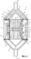
- FIGS. 10 and 11 illustrate the valve members 158 and 184 ( FIG. 8 ) as the valve member 158 unseals the bore 134 and the valve member 184 unseals the bore 188.
- a vacuum is drawn in the vacuum cavity 72b of the first pump chamber 72 and the vacuum cavity 74b of the second pump chamber 74 is vented.
- This creates a pressure differential between the vacuum cavities 72b, 74b of the first and second pump chambers 72, 74, which causes the diaphragm 92 in the first pump chamber 72 to move in the direction of arrows "B" in FIGS. 10 and 11 to collapse the vacuum cavity 72b of the first pump chamber 72.
- the fluid cavity 72a of the first pump chamber 72 expands to draw irrigation fluid into the fluid cavity 72a through the first check valve 80 ( FIG. 11 ).
- the piston shaft 112 moves in the direction indicated by arrows "B" in FIG. 10 to move the piston shaft 112 in the direction of arrow "B"
- the piston shaft 112 causes corresponding movement of the diaphragm 100 within the second pump chamber 74 to force irrigation fluid from the fluid cavity 74a of the second pump chamber 74 through the check valve 90 ( FIG. 11 ). Movement of the diaphragm 100 also causes expansion of the vacuum cavity 74b of the second pump chamber 74.
- the diaphragm 94 is positioned to engage the valve shaft 180 of the atmosphere valve assembly 174 and the valve member 158 of the vacuum valve assembly 150 when the diaphragm 94 moves in the direction indicated by arrows "B" to unseal the bore 130 connecting the vacuum chamber 74b of the second pump chamber 74 to the vacuum chamber 130 and to unseal the bore 186 connecting the vacuum cavity 72b of the first pump chamber 72.
- this pressure differential within the vacuum cavities 72b, 74b of the first and second pump chambers 72, 74 causes the diaphragm 94 to change direction and move in the direction of arrow "A" ( FIG. 8 ).
- the diaphragms 94 and 100 will continue to operate in this manner to provide a pressurized supply of irrigation fluid to the irrigation and suction wand 22 ( FIG. 1 ).
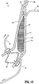
- FIGS. 12 and 13 illustrate an alternate suction and irrigation system shown generally as 200 that includes an alternative fluid pump shown generally as fluid pump 216.
- the fluid pump 216 includes a base member 218, a compression member 220, and a bellows 222.
- the compression member 220 has a first end 220a that is pivotally supported on the base member 218 by a pivot member 221 which may have a variety of configurations.
- the irrigation fluid supply 212 includes a compressible pouch 224 that defines a receptacle that receives irrigation fluid.
- the compressible pouch 224 is supported between the base member 218 and the compression member 220.
- the compressible pouch 224 is supported on a hook member 230 that also supports the base member 218.
- the compressible pouch 224 can be supported on the base member 218 using a hook or other type of coupling member.
- the bellows 222 is secured to ends of the base member 218 and the compression member 220 opposite the pivot member 221.
- the bellows 222 is movable between contracted and expanded configurations to pivot the compression member 220 in relation to the base member 218 to pressurize the irrigation fluid within the compressible pouch 224.
- the bellows 222 is connected to the vacuum source 14 by a fluid conduit 28 to control expansion and contraction of the bellows 222.
- the pressure within the bellows 222 is controlled with the vacuum source 12 to maintain the pressure of the irrigation fluid within the compressible pouch 224 constant.
- the vacuum assisted suction and irrigation systems 10 and 200 operate in substantially similar manners. More specifically, a clinician grasps the proximal body portion 34 of the suction and irrigation wand 22 and manipulates the wand to position a distal end of the distal body portion 40 adjacent a surgical site (not shown). Although not shown, this may include inserting the distal body portion 40 of the suction and irrigation wand 22 through a cannula assembly to access a surgical site. If the clinician requires suction at the surgical site, e.g., to remove blood or debris, the clinician can actuate the suction valve 36 to draw material from the surgical site into the channel 42 of the suction and irrigation wand 22.
- All material withdrawn into the suction and irrigation wand 22 is delivered to the suction container 20 via the fluid conduit 32.
- the clinician can actuate the irrigation valve 38 to deliver fluid to the channel 42 of the distal body portion 40 of the suction and irrigation wand 22.
- vacuum from the vacuum source 14 assists in pressurizing the irrigation fluid to supply the irrigation fluid to the suction and irrigation wand 22.
- the housing 350 of the fluid pump 316 defines two pump chambers 372, 374 ( FIG. 18 ).
- the first pump chamber 372 is defined between the first body portion 358 and the first cover portion 362 and the second pump chamber 374 is defined between the second body portion 360 and the second cover portion 364.
- the first pump chamber 372 defines an inlet opening 376 ( FIG. 18 ) and a fluid outlet opening 378 ( FIG. 20 ).
- Each of the inlet and outlet openings 376, 378 is sealed by a check valve 380, 382, respectively.
- the second pump chamber 374 defines a fluid inlet opening 384 and a fluid outlet opening 386 which are sealed by check valves 388, 390, respectively.
- the first pump chamber 372 is divided into a fluid cavity 372a and a vacuum cavity 372b by a diaphragm 392.
- the diaphragm 392 includes an outer flexible portion 394 of reduced thickness and a central more rigid portion 396 that is configured to support a first piston or shaft holder 398.
- the second pump chamber 374 is also divided into a fluid cavity 374a and a vacuum cavity 374b by a diaphragm 400.
- the diaphragm 400 includes an outer flexible portion 402 of reduced thickness and a central more rigid portion 404 that is configured to support a piston or shaft holder 406.
- the central housing portion 356 of the housing 350 defines a bore 408 ( FIG. 19 ) that that extends between the first and second pump chambers 372, 374, respectively.
- the bore 408 receives a piston shaft 410 that has a first end secured to the shaft holder 398 and a second end secured to the shaft holder 406.
- movement of the first shaft holder 398 within the first pump chamber 372 causes corresponding movement of the shaft holder 406 within the second pump chamber 374.
- FIG. 18 illustrates a cross-sectional view of the fluid pump 316.
- the inlet manifold 352 defines a bifurcated or Y-shaped fluid channel 420 that communicates with the inlet openings 376, 384 of the first and second pump chambers 372, 374, respectively.
- the outlet manifold 354 also defines a Y-shaped fluid channel 422 that has an outlet 422a that communicates with the outlet openings 378, 386 of the first and second pump chambers 372, 374, respectively.
- the check valves 380, 382, 388, and 390 are configured to allow fluid to flow through the housing 350 of the fluid pump 316 in one direction, i.e., into the first and second pump chambers 372, 374 from the inlet manifold 352 and out of the first and second pump chambers 372, 374 through the outlet manifold 354.
- FIG. 19 illustrates a cross-sectional view of the fluid pump 316 showing a vacuum chamber 430 defined within the housing 350.
- the central housing portion 356 and the first and second body portions 358, 360 of the housing 350 of the fluid pump 316 define the vacuum chamber 430 and a vacuum port 432.
- the vacuum port 432 is coupled to a vacuum source 14 ( FIG. 1 ) by a conduit 328 ( FIG. 14 ).
- the conduit 328 is oriented vertically and extends from a lower end of the housing 316.
- the vacuum port 432 defines a channel 432a that communicates with the vacuum chamber 430.
- the first body portion 358 defines a bore 434 that communicates the vacuum chamber 430 with the vacuum cavity 372b of the first pump chamber 372.
- the second body portion 360 defines a bore 436 that communicates the vacuum chamber 430 with the vacuum cavity 374b of the second pump chamber 374.
- the bores 434, 436 are provided to apply a vacuum to the vacuum cavities 372b, 374b of the first and second pump chambers 372, 374 of the fluid pump 16 to control movement of the diaphragms 394, 400 within the first and second pump chambers 372, 374, respectively, as described in more detail below.
- the central housing portion 356 of the housing 350 of the fluid pump 316 defines a bore 440 that receives a vacuum valve assembly 450.
- the vacuum valve assembly 450 includes a valve shaft 456 and valve members 458, 460 that are positioned to alternately seal the bores 434, 436 of the first and second body portions 358, 360, respectively.
- the valve shaft 356 connects the valve member 458 to the valve member 460 and is movable between a first end stroke position in which the valve member 458 fully seals the bore 434 of the first body portion 358 while the bore 436 of the second body portion 360 remains unsealed and a second end stroke position in which the valve member 460 fully seals the bore 436 of the second body portion 360 while the bore 434 of the first body portion 358 remains unsealed.
- end stroke position means the position in which the valve shaft is at one of the ends of it stroke with one valve fully open and the other valve fully closed.
- the central housing portion 356 of the housing 350 of the fluid pump 316 also defines a bore 470 ( FIG. 19 ) that receives an atmosphere valve assembly 474.
- the first and second body portions 358, 360 define bores 486, 488, respectively.
- the atmosphere valve assembly 474 includes a valve shaft 480 and valve members 482, 484 that are positioned to alternately seal the bores 486, 488 as the valve shaft 480 moves between its end stroke positions.
- the bores 486, 488 connect the vacuum cavities 372b, 374b of the first and second pump chambers 372, 374 with atmosphere channels 490 formed in the first and second body portions 358, 360.
- valve member 484 of the atmosphere valve assembly 474 moves to a position to unseal the bore 488 connecting the vacuum cavity 374b of the second pump chamber 374 to the atmosphere channels 490 and the valve member 482 moves to a position to seal the bore 486 connecting the vacuum cavity 372b of the first pump chamber 372 to the atmosphere channels 490.
- valve shaft 456 of the vacuum valve assembly 450 moves the valve member 460 of the vacuum valve assembly 450 to a position to seal the bore 436 connecting the vacuum chamber 430 to the vacuum cavity 374b and the valve member 458 moves to a position to unseal the bore 434 connecting the vacuum chamber 430 to the vacuum cavity 372b of the first pump chamber 372.
- the fluid cavity 374a of the pump chamber 374 is expanded to draw fluid into the fluid cavity 372a through the check valve 388 ( FIG. 18 ).
- irrigation fluid is forced from the fluid cavity 372a of the first pump chamber 372 through the check valve 382 and into the fluid outlet manifold 354.
- the fluid cavity 372a of the first pump chamber 372 expands to draw irrigation fluid into the fluid cavity 372a through the first check valve 380 ( FIG. 20 ).
- the piston shaft 410 causes corresponding movement of the diaphragm 400 in the second pump chamber 374 to force irrigation fluid from the fluid cavity 374a of the second pump chamber 374 through the check valve 390 ( FIG. 20 ) and into the outlet manifold 354.
- the vacuum cavity 374b of the second pump chamber 374 is vented through the bore 486 ( FIG. 21 ) via the open valve 482.
- the shaft holder 398 is positioned to engage the end of the valve shaft 480 of the atmosphere valve assembly 474 and the end of the valve shaft 456 of the vacuum valve assembly 450 when the shaft holder 398 approaches its end stroke position within the first pump chamber 372 This will unseal the bore 436 to connect the vacuum chamber 374b of the second pump chamber 374 to the vacuum chamber 430 and to seal the bore 486 to connect the vacuum cavity 372b of the first pump chamber 372 to the atmosphere channels 490.
- this difference in pressure in the vacuum cavities 372b, 374b of the first and second pump chambers 372, 374 causes the diaphragm 394 to change direction to movement in the direction of arrow "J" ( FIG. 19 ) to restart the pump cycle.
- the diaphragms 394 and 400 will continue to operate in this manner to provide a pressurized supply of irrigation fluid to the irrigation and suction wand 22 ( FIG. 1 ).
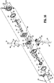
- the diaphragm 392 forms a piston assembly 500 with the shaft holder 398.
- the piston assembly 500 also includes a biasing mechanism 502 that is secured to the side of the shaft holder 398 opposite to the diaphragm 392.
- the side of the shaft holder 398 opposite to the diaphragm 392 defines an annular recess 504 that receives the biasing mechanism 502 which includes an annular spring 506 and an annular plate 508.
- the annular plate 508 includes an annular shoulder 510 that is engaged by a locking plate 512 to secure the biasing mechanism 502 within the annular recess 504 for movement between retracted and advanced positions.
- the annular spring 506 is received within the annular recess 504 and urges the annular spring plate 508 inwardly towards the first body portion 358 of the housing 350.
- the locking plate 512 can be secured to the shaft holder 398 with screws or the like and is positioned to engage the shoulder 510 of the spring plate 508 to retain the spring plate 508 within the annular recess 504.
- the annular spring 506 can be in the form of one or more wave springs although the use of other spring types is envisioned.
- the diaphragm 400 forms a piston assembly 520 with the shaft holder 406.
- the piston assembly 520 also includes a biasing mechanism 522 that is secured to a side of the shaft holder 406 opposite to the diaphragm 400.
- the side of the shaft holder 406 opposite to the diaphragm 400 defines an annular recess 524 that receives the biasing mechanism 522 which includes an annular spring 526 and an annular spring plate 528.
- the annular spring plate 528 includes an annular shoulder 530 that is engaged by a locking plate 532 to secure the biasing mechanism 522 within the annular recess 524 for movement between retracted and advanced positions.
- the annular spring 526 is received within the annular recess 524 and urges the annular spring plate 528 towards its advanced position inwardly towards the second body portion 360 of the housing 350.
- the locking plate 532 can be secured to the shaft holder 406 by screws or the like and is positioned to engage the shoulder 530 of the spring plate 528 to retain the spring plate 528 within the annular recess 524.
- the annular spring 526 can be in the form of one or more wave springs although the use of other spring types is envisioned. The purpose and operation of the biasing mechanisms 502 and 522 is described in further detail below.
- opposite ends of the valve shaft 456 of the vacuum valve assembly 450 and valve shaft 480 of the atmosphere valve assembly 474 positioned within the first and second pump chambers 372, 374 are secured together by frame members 540 and 542, respectively.
- the frame members 540 and 542 are formed of a ferromagnetic material and function to couple the valve shafts 456 and 480 together to restrict the vacuum valve assembly 450 and atmosphere valve assembly 474 to unified movement.
- the first and second covers 362 and 364 each support an outer magnet 550 and 552, respectively that is positioned to attract one of the piston assemblies 500 and 520 to its end stroke position.
- the piston assembly 500 includes a piston plate 560 that is formed of a ferromagnetic material and the piston assembly 520 includes a piston plate 562 that is formed of a ferromagnetic material.
- the magnets 550 and 552 are positioned to ensure that the piston assemblies 500 and 520 are in their end stroke positions when the fluid pump 316 is stopped.
- the valve assemblies 450 and 474 are also urged to and retained in their end stroke positions with the valves 456, 458, 482 and 484 in fully open or fully closed positions.
- Each of the first and second housing portions 358, 360 also supports an inner magnet 570 and 572, respectively ( FIG. 21 ).
- the inner magnets 570 and 572 are annular and are positioned to attract the frame members 540 and 542 to delay opening and closing of the respective valve assemblies 450 and 474 during operation of the fluid pump 316. More specifically, the inner magnets 570 and 572 retain the valve shafts 456 and 480 in their end stroke positions as the piston shaft 410 changes direction to maintain the valves 456, 458, 482 and 484 in their fully open or fully closed positions for a longer period of time to minimize the likelihood of stalling of the fluid pump 316.
- the biasing mechanisms 502, 522 also delay the opening and closing of the valves 456, 458, 482 and 484. More specifically, the biasing mechanisms 502, 522 are positioned to engage the respective frame members 540, 542 to urge the frame members 540, 542 and the respective valve assemblies 450 and 474 that the frame members 540, and 542 are coupled to their end stroke positions when the piston assemblies 500 and 520 are positioned adjacent to the first and second body portions 358 and 360 of the housing 350.
- the plate 508 of the biasing mechanism 502 engages the frame member 540 and pushes the frame member 540 towards the first body portion 358 to move the valve assemblies 450 and 474 to their end stroke position.
- the inner magnet 570 and the biasing mechanism 502, 522 will retain the frame 540 in position against the first body portion 358 of the housing 350 while the piston assemblies 500, 520 begin to change direction to maintain the valve assemblies 450 and 474 in their current end stroke position.
- the magnets 550, 552, 570, and 572 ensure that the piston assemblies 500, 520 are not in transit, i.e., between fully open and fully closed positions, when the fluid pump 316 is stopped to facilitate restart of the fluid pump 316.
- the biasing mechanisms 502 and 522 are configured to delay transitioning of the valve assemblies 450 and 474 by about 1 mm of stroke of the piston shaft 410 to reduce transition losses.
- the biasing mechanisms 502 and 522, the frame members 540 and 542, and the magnets 550, 552, 570, and 572 minimize the portion of the stroke of the piston shaft 410 in which the valve assemblies 150 and 174 are in a transit state, i.e., when all of the valves controlling a vacuum state within the vacuum cavities 372b and 374b of the first and second pump chambers 372 and 374, respectively, are open or between their end stroke positions.
- the transit state depletes the vacuum from both of the vacuum cavities 372b and 374b. In this position, the pump 316 would never restart.
- the mechanisms described above prevent stoppage of the fluid pump in the transit state.
Landscapes
- Health & Medical Sciences (AREA)
- Heart & Thoracic Surgery (AREA)
- Engineering & Computer Science (AREA)
- Hematology (AREA)
- Animal Behavior & Ethology (AREA)
- Veterinary Medicine (AREA)
- Anesthesiology (AREA)
- Biomedical Technology (AREA)
- Public Health (AREA)
- Life Sciences & Earth Sciences (AREA)
- General Health & Medical Sciences (AREA)
- Vascular Medicine (AREA)
- General Engineering & Computer Science (AREA)
- Mechanical Engineering (AREA)
- Pulmonology (AREA)
- Reciprocating Pumps (AREA)
- External Artificial Organs (AREA)
Applications Claiming Priority (3)
| Application Number | Priority Date | Filing Date | Title |
|---|---|---|---|
| US201862750301P | 2018-10-25 | 2018-10-25 | |
| US16/589,651 US20200129678A1 (en) | 2018-10-25 | 2019-10-01 | Vacuum driven suction and irrigation system |
| US16/656,973 US11471660B2 (en) | 2018-10-25 | 2019-10-18 | Vacuum driven suction and irrigation system |
Publications (2)
| Publication Number | Publication Date |
|---|---|
| EP3643338A2 true EP3643338A2 (fr) | 2020-04-29 |
| EP3643338A3 EP3643338A3 (fr) | 2020-07-22 |
Family
ID=68382202
Family Applications (1)
| Application Number | Title | Priority Date | Filing Date |
|---|---|---|---|
| EP19205465.8A Withdrawn EP3643338A3 (fr) | 2018-10-25 | 2019-10-25 | Système d'aspiration et d'irrigation actionné par dépression |
Country Status (2)
| Country | Link |
|---|---|
| US (1) | US11471660B2 (fr) |
| EP (1) | EP3643338A3 (fr) |
Families Citing this family (5)
| Publication number | Priority date | Publication date | Assignee | Title |
|---|---|---|---|---|
| AU2022483569A1 (en) * | 2022-10-25 | 2025-05-08 | The Cleveland Clinic Foundation | Ambulatory fluid drainage and collection device |
| US12564669B2 (en) * | 2022-10-25 | 2026-03-03 | The Cleveland Clinic Foundation | Ambulatory fluid drainage and collection device |
| AU2024225341A1 (en) | 2023-02-21 | 2025-09-04 | Osteal Therapeutics, Inc. | Methods of treating a localized infection with locally administered antibiotics |
| US20240277356A1 (en) * | 2023-02-22 | 2024-08-22 | Neuravi Limited | Cyclic aspiration system producing a cyclic aspiration pressure waveform using a dual pressure generator receptacle in lieu of a vacuum pump |
| CN119679502B (zh) * | 2024-12-11 | 2025-08-08 | 北京市耳鼻咽喉科研究所(北京市耳鼻咽喉头颈外科研究中心) | 一种正负压可调式吸引冲洗多功能手术解剖系统 |
Family Cites Families (58)
| Publication number | Priority date | Publication date | Assignee | Title |
|---|---|---|---|---|
| US2915222A (en) * | 1956-03-22 | 1959-12-01 | Bernard S Purinton | Flower watering mechanisms |
| US3640277A (en) * | 1968-12-09 | 1972-02-08 | Marvin Adelberg | Medical liquid administration device |
| US3572980A (en) * | 1969-02-17 | 1971-03-30 | Rotron Inc | Resonant pump using flat disc springs |
| US3960294A (en) * | 1975-06-18 | 1976-06-01 | Bernard Rodolphe J | Viscous material dispenser |
| US4033479A (en) * | 1976-07-26 | 1977-07-05 | Nasa | Pressure modulating valve |
| US4284209A (en) * | 1979-06-21 | 1981-08-18 | Barbour Jr Robert E | Device and method for collecting blood plasma |
| US4386888A (en) * | 1980-09-29 | 1983-06-07 | Mccann's Engineering And Manufacturing Company | Double diaphragm operated reversing valve pump |
| US4381180A (en) * | 1981-07-13 | 1983-04-26 | Sell John R | Double diaphragm pump with controlling slide valve and adjustable stroke |
| US4604089A (en) * | 1983-08-15 | 1986-08-05 | Codman & Shurtleff, Inc. | Pressure regulated irrigation system for arthroscopy |
| US4613327A (en) * | 1984-01-26 | 1986-09-23 | Tegrarian Haig V | Apparatus for infusing blood and other related fluids into a patient's body |
| US4735613A (en) * | 1986-10-23 | 1988-04-05 | Biomedical Dynamics Corporation | Pressure infusion device |
| US4981418A (en) * | 1989-07-25 | 1991-01-01 | Osmonics, Inc. | Internally pressurized bellows pump |
| US5391145A (en) * | 1990-01-26 | 1995-02-21 | Dorsey, Iii; James H. | Irrigation control valve for endoscopic instrument |
| US5573504A (en) * | 1990-01-26 | 1996-11-12 | C. R. Bard, Inc. | Composite irrigation and suction probe and valve |
| US5188591A (en) * | 1990-01-26 | 1993-02-23 | Dorsey Iii James H | Irrigation control valve for endoscopic instrument |
| US5125910A (en) * | 1991-02-19 | 1992-06-30 | Dexide, Inc. | Surgical endoscopic suction/irrigation cannula assembly |
| US5536254A (en) * | 1992-02-20 | 1996-07-16 | Advanced Surgical Products, Inc. | Laparoscopic irrigation bottle pump |
| CA2083555A1 (fr) * | 1992-11-23 | 1994-05-24 | David H. Laing | Infuseur portable |
| US5391060A (en) * | 1993-05-14 | 1995-02-21 | The Aro Corporation | Air operated double diaphragm pump |
| US5472420A (en) * | 1993-06-03 | 1995-12-05 | Infusion Technologies Corporation | Valve system and method for control of an infusion pump |
| AU1755895A (en) * | 1994-03-02 | 1995-09-18 | Plum Kemi Produktion A/S | A dispensing device for dispensing liquid substance from a pouch |
| US5415531A (en) * | 1994-04-06 | 1995-05-16 | Binks Manufacturing Company | Piston pump for fluent materials |
| US5542918A (en) | 1995-01-06 | 1996-08-06 | Zimmer, Inc. | Vacuum driven fluid pump for an aspiration/irrigation instrument |
| US5720728A (en) * | 1996-03-25 | 1998-02-24 | Mallinckrodt Medical, Inc. | Teardrop shaped pressurizing apparatus |
| US5927954A (en) * | 1996-05-17 | 1999-07-27 | Wilden Pump & Engineering Co. | Amplified pressure air driven diaphragm pump and pressure relief value therefor |
| US6079959A (en) * | 1996-07-15 | 2000-06-27 | Saint-Gobain Performance Plastics Corporation | Reciprocating pump |
| US5807313A (en) * | 1996-07-19 | 1998-09-15 | C. R. Bard, Inc. | Battery powered surgical irrigator |
| DE69731472T2 (de) * | 1996-08-15 | 2005-10-20 | Deka Products Ltd. Partnership | Pumpe und system zur medizinischen irrigation |
| US5758563A (en) * | 1996-10-23 | 1998-06-02 | Holcom Co. | Fluid driven reciprocating pump |
| AU6683498A (en) * | 1997-03-03 | 1998-09-22 | Medical Solutions, Inc. | Method and apparatus for pressure infusion and temperature control of infused liquids |
| US7776014B2 (en) * | 1998-01-29 | 2010-08-17 | Peter Visconti | Disposable surgical suction/irrigation trumpet valve tube cassette |
| US6257845B1 (en) * | 1998-07-14 | 2001-07-10 | Wilden Pump & Engineering Co. | Air driven pumps and components therefor |
| US6176847B1 (en) * | 1999-05-14 | 2001-01-23 | Circon Corporation | Surgical irrigation system incorporating flow sensor device |
| US6419654B1 (en) * | 2000-02-01 | 2002-07-16 | Jeffrey S. Kadan | Diagnostic needle arthroscopy and lavage system |
| TW499548B (en) * | 2000-06-02 | 2002-08-21 | Tokyo Electron Ltd | Dual diaphragm pump |
| US6958058B1 (en) | 2001-05-18 | 2005-10-25 | Medsafe Inc. | Methods and devices for pumping fluid and performing surgical procedures |
| US20050084395A1 (en) | 2003-10-17 | 2005-04-21 | Kang Jing X. | Vacuum driven pump for a lavage instrument |
| US7867196B1 (en) * | 2005-09-13 | 2011-01-11 | Medsafe, Llc | Pump and method having reduced pressure and friction for providing fluid, especially for surgical procedures |
| US20070092385A1 (en) * | 2005-10-20 | 2007-04-26 | Petrie Pe Greg A | Pump and valve actuator system and method |
| US8052644B2 (en) * | 2005-12-14 | 2011-11-08 | Stryker Corporation | Surgical irrigation system |
| US7399168B1 (en) * | 2005-12-19 | 2008-07-15 | Wilden Pump And Engineering Llc | Air driven diaphragm pump |
| US7458309B2 (en) * | 2006-05-18 | 2008-12-02 | Simmons Tom M | Reciprocating pump, system or reciprocating pumps, and method of driving reciprocating pumps |
| US8162923B2 (en) * | 2006-09-06 | 2012-04-24 | Calibra Medical, Inc. | Disposable infusion device with automatic unlocking mechanism |
| MX340210B (es) * | 2008-01-23 | 2016-06-29 | Deka Products Ltd Partnership * | Componentes desechables para sistemas y métodos de autoconexión de una linea de fluido. |
| US9518577B2 (en) | 2008-06-27 | 2016-12-13 | Lynntech, Inc. | Apparatus for pumping a fluid |
| IT1391274B1 (it) * | 2008-08-08 | 2011-12-01 | Medica S R L Ab | Sistema di irrigazione ed aspirazione, in particolare per chirurgia laparoscopica |
| US8262366B2 (en) * | 2009-03-30 | 2012-09-11 | Simmons Tom M | Piston systems having a flow path between piston chambers, pumps including a flow path between piston chambers, and methods of driving pumps |
| US8534282B2 (en) * | 2009-08-21 | 2013-09-17 | Columbus Oral And Maxillofacial Surgery P.S.C. | Flexible self-inflating resuscitator squeeze bag automation device, system, and method |
| US20110306941A1 (en) * | 2010-06-14 | 2011-12-15 | Chandrasekar N R | Portable Lavage Apparatus |
| CA2874443A1 (fr) * | 2011-05-13 | 2012-11-22 | Vascular Technology Inc. | Aspiration/irrigation telecommandees pour chirurgie |
| US9180252B2 (en) * | 2012-04-20 | 2015-11-10 | Bayer Medical Care Inc. | Bellows syringe fluid delivery system |
| US9822770B2 (en) * | 2012-09-17 | 2017-11-21 | The Brothers Dietrich | Pump for transfer of liquids containing suspended solids |
| US8858502B2 (en) * | 2012-10-10 | 2014-10-14 | Alcon Research, Ltd. | Systems and methods for external pressure sensing |
| PL3102828T3 (pl) * | 2014-02-07 | 2020-02-28 | Graco Minnesota Inc. | Układ napędowy do bezpulsacyjnej pompy wyporowej |
| US10537471B2 (en) * | 2014-04-17 | 2020-01-21 | Novartis Ag | Hydraulic pump for ophthalmic surgery |
| JP6941570B2 (ja) * | 2018-01-19 | 2021-09-29 | 日本ピラー工業株式会社 | ローリングダイアフラムポンプ |
| JP2019183839A (ja) * | 2018-04-02 | 2019-10-24 | グラコ ミネソタ インコーポレーテッド | ダイアフラムポンプキャビティ内の減圧シフト |
| US20200324040A1 (en) * | 2019-04-09 | 2020-10-15 | Covidien Lp | Vacuum driven suction and irrigation system |
-
2019
- 2019-10-18 US US16/656,973 patent/US11471660B2/en active Active
- 2019-10-25 EP EP19205465.8A patent/EP3643338A3/fr not_active Withdrawn
Also Published As
| Publication number | Publication date |
|---|---|
| EP3643338A3 (fr) | 2020-07-22 |
| US20200129751A1 (en) | 2020-04-30 |
| US11471660B2 (en) | 2022-10-18 |
Similar Documents
| Publication | Publication Date | Title |
|---|---|---|
| EP3643338A2 (fr) | Système d'aspiration et d'irrigation actionné par dépression | |
| KR101853988B1 (ko) | Iv 펌프 및 카셋트 시스템 | |
| US8142397B2 (en) | Pump module method for a medical fluid dispensing system | |
| US10940244B2 (en) | Vacuum powered saline injection system | |
| US7337538B2 (en) | Methods and apparatuses for joining a pumping cartridge to a pump drive | |
| US8376983B2 (en) | Method for aspirating fluid utilizing a dual cylinder vacuum pump | |
| US20230201430A1 (en) | Hydraulic pumping system for expression of brast milk | |
| CN1980609A (zh) | 医用泵 | |
| JP2007507252A (ja) | 吸引物収集バッグに対する取付けのための蠕動ポンプ用継手 | |
| US9683562B2 (en) | Low-force pumping segment | |
| EP2101840B1 (fr) | Appareil d'aide cardiocirculatoire | |
| US12173704B2 (en) | Disposable dual-action reciprocating pump assembly | |
| AU2019253809A1 (en) | Vacuum driven suction and irrigation system | |
| US20200129678A1 (en) | Vacuum driven suction and irrigation system | |
| US12188469B2 (en) | Using silicone o-rings in dual action irrigation pump | |
| EP3673935B1 (fr) | Utilisation d'un ballonnet comme amortisseur pour le trou d'une pompe alternative | |
| WO2026089650A1 (fr) | Dispositif de pompe à fluide utilisé dans des applications de sciences de la vie | |
| JP2025114497A (ja) | 手動駆動往復ポンプ |
Legal Events
| Date | Code | Title | Description |
|---|---|---|---|
| PUAI | Public reference made under article 153(3) epc to a published international application that has entered the european phase |
Free format text: ORIGINAL CODE: 0009012 |
|
| STAA | Information on the status of an ep patent application or granted ep patent |
Free format text: STATUS: THE APPLICATION HAS BEEN PUBLISHED |
|
| AK | Designated contracting states |
Kind code of ref document: A2 Designated state(s): AL AT BE BG CH CY CZ DE DK EE ES FI FR GB GR HR HU IE IS IT LI LT LU LV MC MK MT NL NO PL PT RO RS SE SI SK SM TR |
|
| AX | Request for extension of the european patent |
Extension state: BA ME |
|
| PUAL | Search report despatched |
Free format text: ORIGINAL CODE: 0009013 |
|
| AK | Designated contracting states |
Kind code of ref document: A3 Designated state(s): AL AT BE BG CH CY CZ DE DK EE ES FI FR GB GR HR HU IE IS IT LI LT LU LV MC MK MT NL NO PL PT RO RS SE SI SK SM TR |
|
| AX | Request for extension of the european patent |
Extension state: BA ME |
|
| RIC1 | Information provided on ipc code assigned before grant |
Ipc: F04B 43/073 20060101ALI20200618BHEP Ipc: F04B 43/00 20060101ALI20200618BHEP Ipc: A61M 1/00 20060101AFI20200618BHEP Ipc: A61M 3/02 20060101ALI20200618BHEP Ipc: F04B 43/06 20060101ALI20200618BHEP |
|
| STAA | Information on the status of an ep patent application or granted ep patent |
Free format text: STATUS: THE APPLICATION IS DEEMED TO BE WITHDRAWN |
|
| 18D | Application deemed to be withdrawn |
Effective date: 20210123 |