EP3643388B1 - Cyclone accélérateur séparateur de particules solides - Google Patents
Cyclone accélérateur séparateur de particules solides Download PDFInfo
- Publication number
- EP3643388B1 EP3643388B1 EP17914487.8A EP17914487A EP3643388B1 EP 3643388 B1 EP3643388 B1 EP 3643388B1 EP 17914487 A EP17914487 A EP 17914487A EP 3643388 B1 EP3643388 B1 EP 3643388B1
- Authority
- EP
- European Patent Office
- Prior art keywords
- diameter
- air
- solid particles
- accelerating
- cyclone
- Prior art date
- Legal status (The legal status is an assumption and is not a legal conclusion. Google has not performed a legal analysis and makes no representation as to the accuracy of the status listed.)
- Active
Links
Images


Classifications
-
- B—PERFORMING OPERATIONS; TRANSPORTING
- B07—SEPARATING SOLIDS FROM SOLIDS; SORTING
- B07B—SEPARATING SOLIDS FROM SOLIDS BY SIEVING, SCREENING, SIFTING OR BY USING GAS CURRENTS; SEPARATING BY OTHER DRY METHODS APPLICABLE TO BULK MATERIAL, e.g. LOOSE ARTICLES FIT TO BE HANDLED LIKE BULK MATERIAL
- B07B7/00—Selective separation of solid materials carried by, or dispersed in, gas currents
- B07B7/08—Selective separation of solid materials carried by, or dispersed in, gas currents using centrifugal force
- B07B7/083—Selective separation of solid materials carried by, or dispersed in, gas currents using centrifugal force generated by rotating vanes, discs, drums, or brushes
-
- B—PERFORMING OPERATIONS; TRANSPORTING
- B04—CENTRIFUGAL APPARATUS OR MACHINES FOR CARRYING-OUT PHYSICAL OR CHEMICAL PROCESSES
- B04C—APPARATUS USING FREE VORTEX FLOW, e.g. CYCLONES
- B04C5/00—Apparatus in which the axial direction of the vortex is reversed
- B04C5/02—Construction of inlets by which the vortex flow is generated, e.g. tangential admission, the fluid flow being forced to follow a downward path by spirally wound bulkheads, or with slightly downwardly-directed tangential admission
- B04C5/04—Tangential inlets
-
- B—PERFORMING OPERATIONS; TRANSPORTING
- B01—PHYSICAL OR CHEMICAL PROCESSES OR APPARATUS IN GENERAL
- B01D—SEPARATION
- B01D45/00—Separating dispersed particles from gases or vapours by gravity, inertia, or centrifugal forces
- B01D45/12—Separating dispersed particles from gases or vapours by gravity, inertia, or centrifugal forces by centrifugal forces
- B01D45/16—Separating dispersed particles from gases or vapours by gravity, inertia, or centrifugal forces by centrifugal forces generated by the winding course of the gas stream, the centrifugal forces being generated solely or partly by mechanical means, e.g. fixed swirl vanes
-
- B—PERFORMING OPERATIONS; TRANSPORTING
- B04—CENTRIFUGAL APPARATUS OR MACHINES FOR CARRYING-OUT PHYSICAL OR CHEMICAL PROCESSES
- B04C—APPARATUS USING FREE VORTEX FLOW, e.g. CYCLONES
- B04C5/00—Apparatus in which the axial direction of the vortex is reversed
- B04C5/08—Vortex chamber constructions
- B04C5/081—Shapes or dimensions
-
- B—PERFORMING OPERATIONS; TRANSPORTING
- B04—CENTRIFUGAL APPARATUS OR MACHINES FOR CARRYING-OUT PHYSICAL OR CHEMICAL PROCESSES
- B04C—APPARATUS USING FREE VORTEX FLOW, e.g. CYCLONES
- B04C5/00—Apparatus in which the axial direction of the vortex is reversed
- B04C5/08—Vortex chamber constructions
- B04C5/103—Bodies or members, e.g. bulkheads, guides, in the vortex chamber
-
- B—PERFORMING OPERATIONS; TRANSPORTING
- B04—CENTRIFUGAL APPARATUS OR MACHINES FOR CARRYING-OUT PHYSICAL OR CHEMICAL PROCESSES
- B04C—APPARATUS USING FREE VORTEX FLOW, e.g. CYCLONES
- B04C5/00—Apparatus in which the axial direction of the vortex is reversed
- B04C5/12—Construction of the overflow ducting, e.g. diffusing or spiral exits
- B04C5/13—Construction of the overflow ducting, e.g. diffusing or spiral exits formed as a vortex finder and extending into the vortex chamber; Discharge from vortex finder otherwise than at the top of the cyclone; Devices for controlling the overflow
-
- B—PERFORMING OPERATIONS; TRANSPORTING
- B04—CENTRIFUGAL APPARATUS OR MACHINES FOR CARRYING-OUT PHYSICAL OR CHEMICAL PROCESSES
- B04C—APPARATUS USING FREE VORTEX FLOW, e.g. CYCLONES
- B04C9/00—Combinations with other devices, e.g. fans, expansion chambers, diffusors, water locks
-
- F—MECHANICAL ENGINEERING; LIGHTING; HEATING; WEAPONS; BLASTING
- F26—DRYING
- F26B—DRYING SOLID MATERIALS OR OBJECTS BY REMOVING LIQUID THEREFROM
- F26B17/00—Machines or apparatus for drying materials in loose, plastic, or fluidised form, e.g. granules, staple fibres, with progressive movement
- F26B17/10—Machines or apparatus for drying materials in loose, plastic, or fluidised form, e.g. granules, staple fibres, with progressive movement with movement performed by fluid currents, e.g. issuing from a nozzle, e.g. pneumatic, flash, vortex or entrainment dryers
- F26B17/107—Machines or apparatus for drying materials in loose, plastic, or fluidised form, e.g. granules, staple fibres, with progressive movement with movement performed by fluid currents, e.g. issuing from a nozzle, e.g. pneumatic, flash, vortex or entrainment dryers pneumatically inducing within the drying enclosure a curved flow path, e.g. circular, spiral, helical; Cyclone or Vortex dryers
-
- F—MECHANICAL ENGINEERING; LIGHTING; HEATING; WEAPONS; BLASTING
- F26—DRYING
- F26B—DRYING SOLID MATERIALS OR OBJECTS BY REMOVING LIQUID THEREFROM
- F26B5/00—Drying solid materials or objects by processes not involving the application of heat
- F26B5/08—Drying solid materials or objects by processes not involving the application of heat by centrifugal treatment
-
- B—PERFORMING OPERATIONS; TRANSPORTING
- B04—CENTRIFUGAL APPARATUS OR MACHINES FOR CARRYING-OUT PHYSICAL OR CHEMICAL PROCESSES
- B04C—APPARATUS USING FREE VORTEX FLOW, e.g. CYCLONES
- B04C5/00—Apparatus in which the axial direction of the vortex is reversed
- B04C5/12—Construction of the overflow ducting, e.g. diffusing or spiral exits
- B04C5/13—Construction of the overflow ducting, e.g. diffusing or spiral exits formed as a vortex finder and extending into the vortex chamber; Discharge from vortex finder otherwise than at the top of the cyclone; Devices for controlling the overflow
- B04C2005/136—Baffles in the vortex finder
-
- B—PERFORMING OPERATIONS; TRANSPORTING
- B04—CENTRIFUGAL APPARATUS OR MACHINES FOR CARRYING-OUT PHYSICAL OR CHEMICAL PROCESSES
- B04C—APPARATUS USING FREE VORTEX FLOW, e.g. CYCLONES
- B04C9/00—Combinations with other devices, e.g. fans, expansion chambers, diffusors, water locks
- B04C2009/005—Combinations with other devices, e.g. fans, expansion chambers, diffusors, water locks with external rotors, e.g. impeller, ventilator, fan, blower, pump
-
- B—PERFORMING OPERATIONS; TRANSPORTING
- B04—CENTRIFUGAL APPARATUS OR MACHINES FOR CARRYING-OUT PHYSICAL OR CHEMICAL PROCESSES
- B04C—APPARATUS USING FREE VORTEX FLOW, e.g. CYCLONES
- B04C9/00—Combinations with other devices, e.g. fans, expansion chambers, diffusors, water locks
- B04C2009/007—Combinations with other devices, e.g. fans, expansion chambers, diffusors, water locks with internal rotors, e.g. impeller, ventilator, fan, blower, pump
-
- B—PERFORMING OPERATIONS; TRANSPORTING
- B04—CENTRIFUGAL APPARATUS OR MACHINES FOR CARRYING-OUT PHYSICAL OR CHEMICAL PROCESSES
- B04C—APPARATUS USING FREE VORTEX FLOW, e.g. CYCLONES
- B04C9/00—Combinations with other devices, e.g. fans, expansion chambers, diffusors, water locks
- B04C2009/008—Combinations with other devices, e.g. fans, expansion chambers, diffusors, water locks with injection or suction of gas or liquid into the cyclone
Definitions
- the invention relates to dewatering and pulverizing organic and inorganic solid products in different areas of the state of the art, e.g. as food raw materials, in producing vegetable and fruit powder and flours, in agro-industrial wastes, in sludge final disposal from sanitary industries, and sludge and byproducts from several manufacturing industries such as fishing, livestock, poultry, forestry and mining.
- the invention consists of a spinning-top-shaped accelerating cyclone that separates solid particles, which provides dewatered solid products in powder and/or granules.
- Constant research in different areas of the art has been carried out based on the need to regulate the costs associated to the processes of drying, dewatering and pulverizing solid substances, and the processes of collecting solid particulate material.
- Cyclones consisting essentially of a sedimentation chamber operating with centrifugal acceleration instead of gravitational acceleration, are the most commonly used equipment in retrieving or settling solid particles. Cyclones have been used for years to retrieve solid particles due to the lower manufacture and operability cost thereof.
- the physical structure of a cyclone comprises a vertical cylinder with a lower conical section, which forces the descending vortex to change its direction, which results in an increased particle collection as the turning radius is reduced.
- the solid material to be separated enters as mixed with gas through a tangential inlet that said vertical cylinder has, and the separated solid material is removed through an open lower mouth located on the lower conical section. Cyclones are basically simple constructions with no moving parts, which makes maintenance operations easier.
- Cyclones are equipment with very good performance in retrieving solids, but they are not as suitable if the particles to be separated are too small, e.g. with a diameter less than about 10 ⁇ m. Additionally, its efficiency decreases when the particles of the materials to be separated have a tendency to stick, thus remaining stuck in the corners formed by the joints between the upper vertical body and lower conical section, and in the inner walls of the lower cone as said cone is downwardly convergent and has an inner surface affected by the action of gravity and the speed effect on the falling particles as the diameter of the conical part decreases.
- a further drying method uses a variant consisting of a spray drying, which operates by reducing the material to be dried to droplets, then subjecting said droplets to a large amount of hot air in order to provide the necessary heat to dry the liquid.
- spray dryer The equipment that is associated with this method is referred to as spray dryer.
- US6971594 describes an apparatus and method for compressed air vortex flow (circular or rotational flow at high velocity) in grinding solid material.
- the grinding apparatus uses high velocity compressed air in the grinding process for grinding, and also drying, diverse materials including by way of example, but not limited to, glass, grain, paper, plastic, aluminum and granite.
- the grinding apparatus includes an annular upper enclosure defining an upper chamber into which material to be ground is introduced, a conical lower enclosure defining a lower chamber affixed in vertical orientation in tandem with the annular upper enclosure.
- the annular upper enclosure has holes for introducing compressed air in its sidewalls.
- the air is introduced relatively circumferentially into the upper chamber so as to generate a circular vortex flow of air for material grinding and drying to take place.
- the air flow is exhausted through a pipe located in the annular upper enclosure, and the dried material is discharged through a lower end of the lower enclosure.
- US4251243 describes an improved cyclonic separator comprising a lower frustoconical body that has a conical wall, which ends at its lower end with a cylindrical short wall forming the mouth for discharging solid material. At its upper end having a larger diameter, said conical body ends in a radially outwardly directed flange over which an annular lid may be suitably mounted.
- the upper body is formed by a conical wall, whose upper lower diameter end is closed by means of a circular lid through whose center the suction duct is provided and its larger diameter end is inserted in the lower cone.
- US5791066 describes a cyclone dryer comprising a cyclonic chamber consisting of a lower cone-shaped chamber, a lower cylindrical chamber located immediately above the cone, an upper cylindrical chamber located on the lower cylindrical chamber, where both cylindrical chambers have a substantially similar outside diameter. In one embodiment, both cylindrical chambers can be as many as one.
- the lower cone has the material outlet. As the cross section of the cone-shaped chamber gets smaller to the bottom, the air starts to spin upwards, and this way only solid material exits. The high-speed airstream enters the cylindrical chamber and is forced to spirally rotate downwards against the lower, cone-shaped portion, thus creating a downward vortex. An air outlet is on the top, over the cylindrical chambers.
- US4966703 describes a cyclone-type separator for separating two liquid components, one of greater density and the other of lesser density, by means of a separating chamber that is generally tapered from a larger diameter end to a smaller diameter end.
- the separating chamber has an overflow outlet for the less dense component, located at the larger diameter end, and an underflow outlet at the smaller diameter end, for the outflow of the denser component.
- the cyclone comprises a helical flight to direct the flow (the heaviest) downwards, thus accelerating the fluid.
- CN201692732 which corresponds to a utility model, provides a compressed air dewatering equipment; compressed air enters the dewatering equipment which consists of a conical shell body to form a vortex in the cyclone body.
- the dewatering equipment in order to be more efficient, dewaters and cleans the fluid by means of centrifugal force and by the action of baffles that drive the fluid to the bottom of the cyclone.
- the dewatering equipment thus completes the process of removing impurities, oil stains and water in quite big drops.
- the baffles separate air-water in the cyclone body.
- DE1245267 describes a cyclone dust separator into which compressed air is injected through the upper nozzles, where a helical accelerator is provided to take the air/dust particles and directs the densest to the bottom.
- DE 10317772 describes a dust separator with an air current with two series-connected cyclones (1, 2) of different separation, in which the highest cone-shaped cyclonic power is tapered from the inlet with an equipment in order to generate an accelerated air current with a dust-laden air inlet.
- the cyclone has a truncated helical sector with guide plates that enable direct the fluid to the bottom.
- EP 1520505 describes an improved dust/particle collecting arrangement for cyclone separators, wherein the cyclone comprises a lower conical body, a central cylindrical body immediately above the conical body, and a third upper, also cylindrical, body and where the cylindrical central body allows to accelerate the speed of the solid material particles and is the cyclone pressure chamber and comprises a side opening for the acceleration air input, at least one duct projecting from inside the central cylindrical body for the input of the mixture of solid particles and air to the accelerating cyclone located on the opposite side with respect to the side opening for the input of the acceleration air and a rotating turbine located inside said cylindrical central body.
- One of the objects of the present invention is developing a cyclone equipment that separates solid particles and assures an effective separation or retrieval of solid particles powder with low moisture percentage.
- the present invention is a spinning-top-shaped accelerating cyclone that separates solid particles in order to form and separate powdered and/or granulated dewatered, or low-moisture-percentage, solid products.
- the present invention describes a cyclone equipment that separates solid particles powder comprising a lower conical body, a central cylindrical body immediately above the conical body, and a third upper, also cylindrical, body of smaller diameter than the diameter of the central cylindrical body.
- the present invention consists of a spinning-top-shaped accelerating cyclone that separates solid particles and assures an effective separation or retrieval of solid particles powder with low moisture percentage.
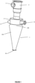
- the accelerating cyclone that separates solid particles of the present invention separates micro-dispersed water from particulate material and comprises in its general structure a lower conical body (1), a central cylindrical body (2) immediately above the conical body (1) whose diameter is smaller than the largest diameter of the conical body cone (1), and a third upper, also cylindrical, body (3) of smaller diameter than the diameter of the central cylindrical body (2).
- the upper cylindrical body (3) is structurally divided into two sections, one upper section of larger diameter and one lower section of smaller diameter. Said upper cylindrical body (3) vents and regulates the process air once the solid particles are separated, and it structurally comprises:
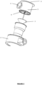
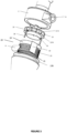
- the central cylindrical body (2) the function of which is to accelerate the speed of the material particles, is called "accelerating cyclone pressure chamber" and consists of the following elements:
- the lower conical body (1) whose function is to allow the output of the solid particles, comprises:
- the particle accelerating cyclone receives the stream of air-borne solid particles with micro-dispersed water through the supply duct (9).
- the air-borne solid particles go directly into the pressure chamber where the rotating turbine (10) and the slotted cylinder (15) are located.
- said rotating turbine (10) is rotating at a speed higher than the speed of the solid particles, due to the air input through the acceleration air inlet (8).
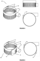
- the rotating turbine (10) generates a circulatory movement of the air, and the elongated pressure vanes (14) generate surface pressures and prevent the reduction of the particle speed, since the elongated pressure vanes (14) move at a higher speed than the particles.
- said pressure vanes (14) are spaced at a minimum distance from the slotted cylinder walls (15) in order to ensure that no solid material remains trapped on the surface of said slotted cylinder.
- the rotary turbine (10) pushes the product down, i.e. towards the lower conical body (1) due to the pressure created by the ejector mechanism.
- the slotted cylinder (15) through its multiplicity of slots, makes the solid material particles not to touch the surface, not to stick or adhere to the walls and, therefore, that they remain suspended inside the cyclone, i.e. it achieves the surface dispersion of the material particles.
- the elongated pressure vanes (14) completely ensure that the solid particles do not get trapped in the slotted cylinder (15).
- the suspended solid particles are displaced by the centrifugal force towards the lower conical body (1) of the accelerating cyclone, achieving its sedimentation and expulsion through the lower opening (18) for the output of the final product from the conical body.
- the concave curve upper section (17B) having the lower conical body (1) at its upper part helps to push the solid particles into said conical body (17A), preventing the particles from sticking to the inlet of the lower conical body (1).
- the acceleration air going into the pressure chamber is driven through an auxiliary fan, which takes the outlet air from the side opening for the acceleration air outlet (5) of the upper cylindrical body (3) and it inputs it again to the accelerating cyclone through the side opening for the acceleration air input (8) of the central cylindrical body (2), said acceleration air generates an air cushion in the pressure chamber.
- the accelerating cyclone is capable of carrying out the following operations:
- cyclone can be a part of an integrated system to separate solid particles, as in Figure 7 , where the system can comprise:
- the procedure for activating the integrated system begins by starting the turbine or turbines (24), then the auxiliary fan (23), then turning on the heater (27) and, finally, by activating the pneumatic lock or star valve (26) and the material feeder (25).
- the procedure comprises the air input, at room temperature, into the inlet duct of the heater in order to increase the air temperature to the set-point or process temperature, necessary to keep the walls of the system free of humidity, in the ducts as much as in the cyclone equipment, and reduce the relative humidity of the input air (preferably, the temperature is kept in the range of about 40 °C to about 70 °C, enough to lower the air relative humidity to levels below 20 % or less); the input of solid material to be treated through the material feeder, which regulates the flow speed of material entering the system; the flow of material then passes to the star valve, where the material atmospheric pressure is changed to negative pressure; then the air-borne solid material enters the high-speed turbine (24), where the air is sucked so that the solid material passes through said turbine (24), and the breaking of the solid input material and the dissociation of the water contained in said solid material take place efficiently; the solid material of smaller size with the dissociated water subsequently enters the accelerating cyclone, where the separation of the water and the powdered solid
- the time elapsed from inputting the material to be treated to forming the final powder product is short, preferably almost instantaneous, and during that time the initial water of the material to be treated is reduced by about 80 %, preferably about 90 %.
- the temperature of the final product does not increase.
- the adjustment of the set-point temperatures is relevant for each material in such a way that it avoids being subjected to the sticky zone and allows the condition of free flowing of the material.
- an acoustic synergy is achieved between the turbine (24) and the accelerating cyclone.
- the turbine creates the ultrasound effect, the cyclone acting as a sounding board, in order to receive the low-frequency waves and higher harmonics that allow the resonance effect to be kept for a longer period.
- the dissociation of the water from the matter is caused by the turbine, the accelerating cyclone producing the effect of containment and separation of the matter with the microdispersed water in a closed system.
- the turbine improves the heat transfer coefficient by receiving the product at negative pressure (vacuum), dissociating the water by physical effects (ultrasound, friction, centrifugation), thus allowing the water particles to be microdispersed and sent at high positive pressure to the system of separation and acceleration of the cyclone.
- the assembly and design allow for dewatering raw materials also at room temperature without application of any additional heat source.
- the acceleration of the particles as created by the auxiliary or high-pressure fan in the internal acceleration chamber of the cyclone is intended to create a better separation of the matter with the microdispersed water and, in turn, preventing the material from adhering to the cyclone walls.
- the auxiliary or high-pressure fan uses the cyclone outlet air to cause the effect of particle acceleration and anti-adhesion, which is efficient as it requires no air with additional heat source, when the system operates with an external heat source through a heater.
- the high-pressure fan takes the dry fine particles as evacuated from the accelerating cyclone and returns them thereto, thus allowing these (fine dry particles) to mix with the wettest input material and facilitating that material with higher humidity to move freely and without adhesion in the accelerating cyclone.
Landscapes
- Engineering & Computer Science (AREA)
- Mechanical Engineering (AREA)
- General Engineering & Computer Science (AREA)
- Physics & Mathematics (AREA)
- Chemical & Material Sciences (AREA)
- Chemical Kinetics & Catalysis (AREA)
- Health & Medical Sciences (AREA)
- Life Sciences & Earth Sciences (AREA)
- Molecular Biology (AREA)
- Geometry (AREA)
- Fluid Mechanics (AREA)
- Cyclones (AREA)
Claims (9)
- Cyclone accélérateur qui sépare des particules solides pour fournir de la poudre et/ou des produits solides granulés déshydratés, avec un faible pourcentage d'humidité, à partir par exemple de matières premières alimentaires, dans la production de poudres et de farines de légumes et de fruits, dans les déchets agro-industriels, dans les boues d'élimination finale des industries d'assainissement, et les boues et sous-produits de plusieurs industries manufacturières telles que la pêche, l'élevage, la volaille, l'industrie forestière et l'industrie minière, comprenant dans sa structure générale un corps conique inférieur (1), un corps cylindrique central (2) immédiatement au-dessus du corps conique (1) dont le diamètre est inférieur au plus grand diamètre du cône de corps conique (1), et un troisième corps supérieur, également cylindrique, (3) d'un diamètre inférieur au diamètre du corps cylindrique central (2) ; dans lequel le corps central cylindrique (2) est la chambre de pression de cyclone ; dans lequel ledit corps central cylindrique (2) comprend :a) une ouverture latérale pour l'entrée d'air d'accélération (8) ;b) au moins un conduit (9) faisant saillie depuis l'intérieur du corps cylindrique central (2) pour l'entrée du mélange de particules solides et d'air, ou encore appelé particules solides en suspension dans l'air, vers le cyclone accélérateur situé sur le côté opposé par rapport à l'ouverture latérale pour l'entrée de l'air d'accélération (8).c) une turbine rotative (10) située à l'intérieur dudit corps central cylindrique (2) ;d) au moins deux aubes de pression allongées (14) réparties symétriquement le long du diamètre de la turbine rotative (10) ; ete) un cylindre intérieur (20) situé à l'intérieur dudit corps central (2) qui est formé par un cylindre non fendu (19) situé dans la partie supérieure du cylindre intérieur (20) et par un cylindre fendu (15), situé sous le cylindre non fendu.
- Cyclone accélérateur selon la revendication 1, dans lequel le corps cylindrique supérieur (3) est divisé structurellement en deux sections, une section supérieure de plus grand diamètre et une section inférieure de plus petit diamètre, et en ce que ledit corps cylindrique supérieur évacue et régule l'air de traitement une fois les particules solides séparées, et comprenant :i) une ouverture supérieure pour la sortie de l'air de traitement (4) ;ii) une ouverture latérale pour la sortie de l'air d'accélération (5), qui est située sur la partie latérale supérieure de la section de plus grand diamètre ;iii) un ensemble de supports radiaux (6) situés intérieurement dans la section supérieure de plus grand diamètre ; etiv) un cône d'ajustement (7) de l'air de sortie, qui est ajustable dans sa position lui permettant d'être ajusté vers le haut ou vers le bas, dont la fonction est de gérer pour réguler la pression interne et la flottabilité des particules et qui est situé à l'intérieur dans la section de plus grand diamètre, immédiatement en dessous de l'ensemble de supports radiaux (6), approximativement à la moitié de la hauteur totale du corps supérieur cylindrique (3).
- Cyclone accélérateur selon l'une quelconque des revendications 1-2, dans lequella turbine rotative (10) comprend une roue formée de deux anneaux parallèles concentriques (12A, 12B) et de plusieurs aubes rectangulaires radiales (13) réparties le long du périmètre de ladite turbine rotative (10) et supportées sur un anneau central (11) ;les deux aubes de pression allongées (14) sont réparties symétriquement le long du diamètre des anneaux (12A, 12B) et réunies perpendiculairement à l'anneau inférieur (12B) de la roue de la turbine rotative (10) ; etla partie du cylindre non fendu (19) est alignée avec les aubes radiales rectangulaires (13) de la turbine rotative (10) et présente une hauteur équivalente ou supérieure à la hauteur des aubes radiales rectangulaires (13) de la turbine rotative (10) et est ménagée avec au moins un mécanisme d'éjection, sur sa surface extérieure.
- Cyclone accélérateur selon l'une quelconque des revendications 1-3, dans lequel le corps conique inférieur (1) comprend :A) une section conique inférieure (17A) ;B) une section supérieure courbe concave (17B), située dans la partie supérieure de la section inférieure conique (17A) ; etC) une ouverture inférieure (18) pour la sortie du produit final à partir de particules solides.
- Cyclone accélérateur selon la revendication 4, dans lequel la section supérieure courbe concave (17B) présente un diamètre plus petit par rapport au diamètre plus grand de la section inférieure conique (17A) et en ce que ladite section supérieure courbe concave (17B) aide à pousser les particules solides jusque dans le corps conique (1).
- Cyclone accélérateur selon la revendication 3, dans lequel les aubes de pression allongées (14) sont parallèles à la paroi interne dudit corps central (2) et d'une longueur équivalente à la hauteur dudit corps central (2).
- Cyclone accélérateur selon la revendication 3, dans lequel le mécanisme d'éjection est formé par une ouverture (22) ménagée dans la partie du cylindre non fendu (19), une aube émergeant tangentiellement (16) des cylindres (19 et 15) au-dessus de l'ouverture (22) et deux supports (21), situés aux extrémités latérales de l'aube émergeant tangentiellement (16), qui permettent l'union entre l'aube émergeant tangentiellement (16) et les cylindres (19 et 15).
- Cyclone accélérateur selon l'une quelconque des revendications 1-7, dans lequel le cylindre fendu (15) présente une multiplicité de fentes et présente un diamètre plus petit que le diamètre extérieur du corps central (2), mais plus grand que le diamètre de la turbine rotative (10).
- Cyclone accélérateur selon la revendication 3, dans lequel les aubes de pression allongées (14) sont espacées d'une distance minimale des parois du cylindre fendu (15) afin de garantir qu'aucun matériau solide ne reste emprisonné sur la surface dudit cylindre fendu (15).
Applications Claiming Priority (1)
| Application Number | Priority Date | Filing Date | Title |
|---|---|---|---|
| PCT/CL2017/050027 WO2018232540A1 (fr) | 2017-06-21 | 2017-06-21 | Cyclone accélérateur séparateur de particules solides |
Publications (3)
| Publication Number | Publication Date |
|---|---|
| EP3643388A1 EP3643388A1 (fr) | 2020-04-29 |
| EP3643388A4 EP3643388A4 (fr) | 2021-01-06 |
| EP3643388B1 true EP3643388B1 (fr) | 2024-09-11 |
Family
ID=64735437
Family Applications (1)
| Application Number | Title | Priority Date | Filing Date |
|---|---|---|---|
| EP17914487.8A Active EP3643388B1 (fr) | 2017-06-21 | 2017-06-21 | Cyclone accélérateur séparateur de particules solides |
Country Status (5)
| Country | Link |
|---|---|
| US (1) | US11548034B2 (fr) |
| EP (1) | EP3643388B1 (fr) |
| JP (1) | JP7005880B2 (fr) |
| AR (1) | AR112311A1 (fr) |
| WO (1) | WO2018232540A1 (fr) |
Families Citing this family (9)
| Publication number | Priority date | Publication date | Assignee | Title |
|---|---|---|---|---|
| WO2018232540A1 (fr) | 2017-06-21 | 2018-12-27 | Biodryingtech Spa | Cyclone accélérateur séparateur de particules solides |
| US11746312B1 (en) | 2019-05-31 | 2023-09-05 | Separator Technology Solutions Us Inc. | Stillage clarification |
| DE102019123034B3 (de) * | 2019-08-28 | 2020-12-03 | Khd Humboldt Wedag Gmbh | Zyklon mit rotierendem Stabkorb |
| US11253874B2 (en) * | 2019-09-19 | 2022-02-22 | X'pole Precision Tools Inc. | Cyclonic dust filter device |
| US11154873B2 (en) * | 2019-09-19 | 2021-10-26 | X'pole Precision Tools Inc. | Multi-cyclonic dust filter device |
| EP4159299B1 (fr) * | 2020-05-28 | 2025-03-26 | Panasonic Intellectual Property Management Co., Ltd. | Dispositif et système de séparation |
| CN113431784B (zh) * | 2021-07-21 | 2023-05-23 | 常州大学 | 一种用于深海天然气水合物流化开采管道输送的螺旋流发生装置 |
| CN118743882B (zh) * | 2024-06-27 | 2025-01-21 | 盐城工学院 | 一种油烟颗粒物捕集用自动调速分离设备及其工作方法 |
| CN120799925B (zh) * | 2025-09-15 | 2025-11-11 | 连云港裕华矿产有限公司 | 一种节能型真空烧结炉加热装置 |
Citations (1)
| Publication number | Priority date | Publication date | Assignee | Title |
|---|---|---|---|---|
| EP1520505B1 (fr) * | 2000-07-06 | 2006-02-15 | John Herbert North | Appareil collecteur de poussière et de particules pour séparateurs cyclone |
Family Cites Families (34)
| Publication number | Priority date | Publication date | Assignee | Title |
|---|---|---|---|---|
| DE1274081B (de) | 1958-08-22 | 1968-08-01 | Siemens Ag | Drehstroemungswirbler zum Trennen von Medien unterschiedlicher Dichte |
| JPS4952169U (fr) * | 1972-08-09 | 1974-05-09 | ||
| JPS5412183U (fr) * | 1977-06-29 | 1979-01-26 | ||
| MX149498A (es) | 1979-10-05 | 1983-11-15 | Salete Garces Felipe | Mejoras a un separador ciclonico operado a succion para materiales solidos pegajosos arrastrados por una corriente gaseosa |
| MY103493A (en) | 1987-11-24 | 1993-06-30 | Conoco Specialty Prod | Cyclone separator |
| US4839969A (en) * | 1988-02-26 | 1989-06-20 | Permian Research Corporation | Drying method and apparatus |
| US5791066A (en) | 1996-08-30 | 1998-08-11 | Hydrofuser Technologies, Inc. | Cyclonic dryer |
| US6971594B1 (en) | 1999-03-23 | 2005-12-06 | Vortex Dehydration Technology, Llc | Apparatus and method for circular vortex air flow material grinding |
| DE20023579U1 (de) * | 1999-05-03 | 2004-12-16 | Dr.Ing.H.C. F. Porsche Ag | Radaufhängung für eine Vorderachse eines Kraftfahrzeuges |
| US6625845B2 (en) * | 2000-03-24 | 2003-09-30 | Sharp Kabushiki Kaisha | Cyclonic vacuum cleaner |
| WO2002038025A1 (fr) * | 2000-11-13 | 2002-05-16 | Matsushita Electric Corporation Of America | Aspirateur cyclonique equipe d'un filtre et d'une brosse filtre |
| KR100433414B1 (ko) * | 2002-05-11 | 2004-05-31 | 삼성광주전자 주식회사 | 진공청소기용 사이클론 집진장치 |
| DE10317772A1 (de) | 2003-04-16 | 2004-12-09 | Bühler AG | Staubabscheider |
| US7351269B2 (en) * | 2003-12-22 | 2008-04-01 | Lau Kwok Yau | Self cleaning filter and vacuum incorporating same |
| KR100539762B1 (ko) * | 2004-03-09 | 2006-01-10 | 엘지전자 주식회사 | 진공청소기의 필터 청소 장치 |
| KR100585692B1 (ko) * | 2004-04-06 | 2006-06-07 | 엘지전자 주식회사 | 진공청소기의 먼지통 |
| US20050242008A1 (en) * | 2004-04-29 | 2005-11-03 | Peter Simpson | Material classifier |
| EP1629761B1 (fr) * | 2004-08-31 | 2012-05-09 | LG Electronics Inc. | Unité de collection de poussière pour aspirateur |
| WO2007022450A1 (fr) | 2005-08-18 | 2007-02-22 | Clean Filtration Technologies, Inc. | Systeme de filtration des liquides utilisant de l'hydrocyclone |
| JP4477565B2 (ja) * | 2005-10-04 | 2010-06-09 | シャープ株式会社 | 集塵器およびそれを備えた電気掃除機 |
| KR100804808B1 (ko) * | 2006-03-24 | 2008-02-20 | 삼성광주전자 주식회사 | 진공청소기의 사이클론 집진장치 |
| US7594941B2 (en) * | 2006-08-23 | 2009-09-29 | University Of New Brunswick | Rotary gas cyclone separator |
| KR101361572B1 (ko) * | 2007-05-28 | 2014-02-14 | 삼성전자주식회사 | 진공청소기의 사이클론 집진장치 |
| CN201692732U (zh) | 2010-06-10 | 2011-01-05 | 中国铝业股份有限公司 | 一种压缩空气脱水装置 |
| US8882999B2 (en) * | 2010-06-17 | 2014-11-11 | Dow Global Technologies Llc | Cleaning assembly for use in fluid filtration systems |
| US8960450B2 (en) | 2010-12-08 | 2015-02-24 | Dow Global Technologies Llc | Apparatus and method for implementing hydroclone based fluid filtration systems with extensible isolated filter stages |
| SE536245C2 (sv) * | 2011-02-14 | 2013-07-16 | Airgrinder Ab | Förfarande och anordning för att söndermala och torka ett material |
| US9050610B2 (en) * | 2012-05-17 | 2015-06-09 | Dow Global Technologies Llc | Hydroclone with inlet flow shield |
| WO2014133701A1 (fr) * | 2013-02-27 | 2014-09-04 | Rohm And Haas Company | Émulsification par balayage de membrane |
| CN105960286B (zh) * | 2013-12-05 | 2019-01-29 | 陶氏环球技术有限责任公司 | 具有改进的清洁组合件的水力旋流器 |
| KR102308501B1 (ko) * | 2015-03-27 | 2021-10-06 | 삼성전자주식회사 | 사이클론 집진장치 및 이를 포함하는 진공 청소기 |
| US10136785B2 (en) * | 2016-08-24 | 2018-11-27 | Shop Vac Corporation | Vacuum cleaner having a filter cleaning mechanism |
| KR102665028B1 (ko) * | 2016-12-13 | 2024-05-13 | 삼성전자주식회사 | 사이클론 집진장치 및 이를 포함하는 진공청소기 |
| WO2018232540A1 (fr) | 2017-06-21 | 2018-12-27 | Biodryingtech Spa | Cyclone accélérateur séparateur de particules solides |
-
2017
- 2017-06-21 WO PCT/CL2017/050027 patent/WO2018232540A1/fr not_active Ceased
- 2017-06-21 EP EP17914487.8A patent/EP3643388B1/fr active Active
- 2017-06-21 JP JP2019571414A patent/JP7005880B2/ja active Active
- 2017-06-21 US US16/624,620 patent/US11548034B2/en active Active
-
2018
- 2018-06-19 AR ARP180101719 patent/AR112311A1/es active IP Right Grant
Patent Citations (1)
| Publication number | Priority date | Publication date | Assignee | Title |
|---|---|---|---|---|
| EP1520505B1 (fr) * | 2000-07-06 | 2006-02-15 | John Herbert North | Appareil collecteur de poussière et de particules pour séparateurs cyclone |
Also Published As
| Publication number | Publication date |
|---|---|
| US11548034B2 (en) | 2023-01-10 |
| JP7005880B2 (ja) | 2022-01-24 |
| WO2018232540A1 (fr) | 2018-12-27 |
| JP2020530809A (ja) | 2020-10-29 |
| EP3643388A1 (fr) | 2020-04-29 |
| EP3643388A4 (fr) | 2021-01-06 |
| AR112311A1 (es) | 2019-10-16 |
| US20200122199A1 (en) | 2020-04-23 |
Similar Documents
| Publication | Publication Date | Title |
|---|---|---|
| EP3643388B1 (fr) | Cyclone accélérateur séparateur de particules solides | |
| RU2100719C1 (ru) | Способ высушивания шламов и устройство для его осуществления | |
| CN1325169C (zh) | 改进的分离装置 | |
| CN106413907B (zh) | 实体鼓壁式螺旋离心机及其运行方法 | |
| US2664966A (en) | Dust arrester | |
| JPH0258989B2 (fr) | ||
| CN108224903A (zh) | 颗粒物料连续分级筛选气流干燥器 | |
| WO2012102619A2 (fr) | Dispositif et procédé de traitement de matériaux | |
| US3771294A (en) | Negative pressure feeder-separator in closed loop product grind and discharging system | |
| CN101631473A (zh) | 用于干燥副产品的方法和设备 | |
| JP7216657B2 (ja) | 粒子の単離及び/又は調製のための装置及び方法 | |
| EA009355B1 (ru) | Способ измельчения материала и удаления влаги из него и устройство для его осуществления (варианты) | |
| US2787374A (en) | Centrifugal classifier | |
| JP2003505244A5 (fr) | ||
| CN106766681A (zh) | 一种错流式气流干燥机 | |
| EP1318871B1 (fr) | Centrifugeuse pour le drainage mecanique et le sechage thermique de boues | |
| JPH11248351A (ja) | 湿潤粉粒体の気流乾燥装置及び気流乾燥方法 | |
| JP2003033916A (ja) | 含水固形物の固液分離方法およびその装置 | |
| CN104194857B (zh) | 生物质原料处理方法及其系统 | |
| US3740929A (en) | Apparatus for collecting finely divided sticky material | |
| RU2079366C1 (ru) | Струйная установка для измельчения сыпучего материала | |
| JPH0380556B2 (fr) | ||
| US2811222A (en) | Apparatus and process for collecting fine particles | |
| CN106733248B (zh) | 气动颗粒分离器 | |
| CN206081911U (zh) | 一种改进的气固分离装置 |
Legal Events
| Date | Code | Title | Description |
|---|---|---|---|
| STAA | Information on the status of an ep patent application or granted ep patent |
Free format text: STATUS: THE INTERNATIONAL PUBLICATION HAS BEEN MADE |
|
| PUAI | Public reference made under article 153(3) epc to a published international application that has entered the european phase |
Free format text: ORIGINAL CODE: 0009012 |
|
| STAA | Information on the status of an ep patent application or granted ep patent |
Free format text: STATUS: REQUEST FOR EXAMINATION WAS MADE |
|
| 17P | Request for examination filed |
Effective date: 20200117 |
|
| AK | Designated contracting states |
Kind code of ref document: A1 Designated state(s): AL AT BE BG CH CY CZ DE DK EE ES FI FR GB GR HR HU IE IS IT LI LT LU LV MC MK MT NL NO PL PT RO RS SE SI SK SM TR |
|
| AX | Request for extension of the european patent |
Extension state: BA ME |
|
| DAV | Request for validation of the european patent (deleted) | ||
| DAX | Request for extension of the european patent (deleted) | ||
| A4 | Supplementary search report drawn up and despatched |
Effective date: 20201203 |
|
| RIC1 | Information provided on ipc code assigned before grant |
Ipc: B04C 5/103 20060101ALI20201127BHEP Ipc: B04C 9/00 20060101ALI20201127BHEP Ipc: B01D 45/14 20060101ALI20201127BHEP Ipc: B04C 11/00 20060101ALI20201127BHEP Ipc: B01D 45/12 20060101AFI20201127BHEP Ipc: F26B 17/10 20060101ALI20201127BHEP Ipc: B04C 5/04 20060101ALI20201127BHEP Ipc: F26B 3/092 20060101ALI20201127BHEP Ipc: B04C 5/13 20060101ALI20201127BHEP Ipc: B04C 5/081 20060101ALI20201127BHEP |
|
| GRAP | Despatch of communication of intention to grant a patent |
Free format text: ORIGINAL CODE: EPIDOSNIGR1 |
|
| STAA | Information on the status of an ep patent application or granted ep patent |
Free format text: STATUS: GRANT OF PATENT IS INTENDED |
|
| INTG | Intention to grant announced |
Effective date: 20240408 |
|
| GRAS | Grant fee paid |
Free format text: ORIGINAL CODE: EPIDOSNIGR3 |
|
| GRAA | (expected) grant |
Free format text: ORIGINAL CODE: 0009210 |
|
| STAA | Information on the status of an ep patent application or granted ep patent |
Free format text: STATUS: THE PATENT HAS BEEN GRANTED |
|
| AK | Designated contracting states |
Kind code of ref document: B1 Designated state(s): AL AT BE BG CH CY CZ DE DK EE ES FI FR GB GR HR HU IE IS IT LI LT LU LV MC MK MT NL NO PL PT RO RS SE SI SK SM TR |
|
| REG | Reference to a national code |
Ref country code: GB Ref legal event code: FG4D |
|
| REG | Reference to a national code |
Ref country code: CH Ref legal event code: EP |
|
| REG | Reference to a national code |
Ref country code: DE Ref legal event code: R096 Ref document number: 602017084854 Country of ref document: DE |
|
| REG | Reference to a national code |
Ref country code: IE Ref legal event code: FG4D |
|
| REG | Reference to a national code |
Ref country code: LT Ref legal event code: MG9D |
|
| PG25 | Lapsed in a contracting state [announced via postgrant information from national office to epo] |
Ref country code: NO Free format text: LAPSE BECAUSE OF FAILURE TO SUBMIT A TRANSLATION OF THE DESCRIPTION OR TO PAY THE FEE WITHIN THE PRESCRIBED TIME-LIMIT Effective date: 20241211 |
|
| REG | Reference to a national code |
Ref country code: NL Ref legal event code: MP Effective date: 20240911 |
|
| PG25 | Lapsed in a contracting state [announced via postgrant information from national office to epo] |
Ref country code: GR Free format text: LAPSE BECAUSE OF FAILURE TO SUBMIT A TRANSLATION OF THE DESCRIPTION OR TO PAY THE FEE WITHIN THE PRESCRIBED TIME-LIMIT Effective date: 20241212 Ref country code: FI Free format text: LAPSE BECAUSE OF FAILURE TO SUBMIT A TRANSLATION OF THE DESCRIPTION OR TO PAY THE FEE WITHIN THE PRESCRIBED TIME-LIMIT Effective date: 20240911 |
|
| PG25 | Lapsed in a contracting state [announced via postgrant information from national office to epo] |
Ref country code: BG Free format text: LAPSE BECAUSE OF FAILURE TO SUBMIT A TRANSLATION OF THE DESCRIPTION OR TO PAY THE FEE WITHIN THE PRESCRIBED TIME-LIMIT Effective date: 20240911 |
|
| PG25 | Lapsed in a contracting state [announced via postgrant information from national office to epo] |
Ref country code: LV Free format text: LAPSE BECAUSE OF FAILURE TO SUBMIT A TRANSLATION OF THE DESCRIPTION OR TO PAY THE FEE WITHIN THE PRESCRIBED TIME-LIMIT Effective date: 20240911 |
|
| PG25 | Lapsed in a contracting state [announced via postgrant information from national office to epo] |
Ref country code: HR Free format text: LAPSE BECAUSE OF FAILURE TO SUBMIT A TRANSLATION OF THE DESCRIPTION OR TO PAY THE FEE WITHIN THE PRESCRIBED TIME-LIMIT Effective date: 20240911 |
|
| PG25 | Lapsed in a contracting state [announced via postgrant information from national office to epo] |
Ref country code: RS Free format text: LAPSE BECAUSE OF FAILURE TO SUBMIT A TRANSLATION OF THE DESCRIPTION OR TO PAY THE FEE WITHIN THE PRESCRIBED TIME-LIMIT Effective date: 20241211 Ref country code: ES Free format text: LAPSE BECAUSE OF FAILURE TO SUBMIT A TRANSLATION OF THE DESCRIPTION OR TO PAY THE FEE WITHIN THE PRESCRIBED TIME-LIMIT Effective date: 20240911 |
|
| PG25 | Lapsed in a contracting state [announced via postgrant information from national office to epo] |
Ref country code: RS Free format text: LAPSE BECAUSE OF FAILURE TO SUBMIT A TRANSLATION OF THE DESCRIPTION OR TO PAY THE FEE WITHIN THE PRESCRIBED TIME-LIMIT Effective date: 20241211 Ref country code: NO Free format text: LAPSE BECAUSE OF FAILURE TO SUBMIT A TRANSLATION OF THE DESCRIPTION OR TO PAY THE FEE WITHIN THE PRESCRIBED TIME-LIMIT Effective date: 20241211 Ref country code: LV Free format text: LAPSE BECAUSE OF FAILURE TO SUBMIT A TRANSLATION OF THE DESCRIPTION OR TO PAY THE FEE WITHIN THE PRESCRIBED TIME-LIMIT Effective date: 20240911 Ref country code: HR Free format text: LAPSE BECAUSE OF FAILURE TO SUBMIT A TRANSLATION OF THE DESCRIPTION OR TO PAY THE FEE WITHIN THE PRESCRIBED TIME-LIMIT Effective date: 20240911 Ref country code: GR Free format text: LAPSE BECAUSE OF FAILURE TO SUBMIT A TRANSLATION OF THE DESCRIPTION OR TO PAY THE FEE WITHIN THE PRESCRIBED TIME-LIMIT Effective date: 20241212 Ref country code: FI Free format text: LAPSE BECAUSE OF FAILURE TO SUBMIT A TRANSLATION OF THE DESCRIPTION OR TO PAY THE FEE WITHIN THE PRESCRIBED TIME-LIMIT Effective date: 20240911 Ref country code: ES Free format text: LAPSE BECAUSE OF FAILURE TO SUBMIT A TRANSLATION OF THE DESCRIPTION OR TO PAY THE FEE WITHIN THE PRESCRIBED TIME-LIMIT Effective date: 20240911 Ref country code: BG Free format text: LAPSE BECAUSE OF FAILURE TO SUBMIT A TRANSLATION OF THE DESCRIPTION OR TO PAY THE FEE WITHIN THE PRESCRIBED TIME-LIMIT Effective date: 20240911 |
|
| REG | Reference to a national code |
Ref country code: AT Ref legal event code: MK05 Ref document number: 1722203 Country of ref document: AT Kind code of ref document: T Effective date: 20240911 |
|
| PG25 | Lapsed in a contracting state [announced via postgrant information from national office to epo] |
Ref country code: NL Free format text: LAPSE BECAUSE OF FAILURE TO SUBMIT A TRANSLATION OF THE DESCRIPTION OR TO PAY THE FEE WITHIN THE PRESCRIBED TIME-LIMIT Effective date: 20240911 |
|
| PG25 | Lapsed in a contracting state [announced via postgrant information from national office to epo] |
Ref country code: PT Free format text: LAPSE BECAUSE OF FAILURE TO SUBMIT A TRANSLATION OF THE DESCRIPTION OR TO PAY THE FEE WITHIN THE PRESCRIBED TIME-LIMIT Effective date: 20250113 Ref country code: IS Free format text: LAPSE BECAUSE OF FAILURE TO SUBMIT A TRANSLATION OF THE DESCRIPTION OR TO PAY THE FEE WITHIN THE PRESCRIBED TIME-LIMIT Effective date: 20250111 |
|
| PG25 | Lapsed in a contracting state [announced via postgrant information from national office to epo] |
Ref country code: RO Free format text: LAPSE BECAUSE OF FAILURE TO SUBMIT A TRANSLATION OF THE DESCRIPTION OR TO PAY THE FEE WITHIN THE PRESCRIBED TIME-LIMIT Effective date: 20240911 Ref country code: SM Free format text: LAPSE BECAUSE OF FAILURE TO SUBMIT A TRANSLATION OF THE DESCRIPTION OR TO PAY THE FEE WITHIN THE PRESCRIBED TIME-LIMIT Effective date: 20240911 |
|
| PG25 | Lapsed in a contracting state [announced via postgrant information from national office to epo] |
Ref country code: EE Free format text: LAPSE BECAUSE OF FAILURE TO SUBMIT A TRANSLATION OF THE DESCRIPTION OR TO PAY THE FEE WITHIN THE PRESCRIBED TIME-LIMIT Effective date: 20240911 Ref country code: AT Free format text: LAPSE BECAUSE OF FAILURE TO SUBMIT A TRANSLATION OF THE DESCRIPTION OR TO PAY THE FEE WITHIN THE PRESCRIBED TIME-LIMIT Effective date: 20240911 |
|
| PG25 | Lapsed in a contracting state [announced via postgrant information from national office to epo] |
Ref country code: PL Free format text: LAPSE BECAUSE OF FAILURE TO SUBMIT A TRANSLATION OF THE DESCRIPTION OR TO PAY THE FEE WITHIN THE PRESCRIBED TIME-LIMIT Effective date: 20240911 Ref country code: CZ Free format text: LAPSE BECAUSE OF FAILURE TO SUBMIT A TRANSLATION OF THE DESCRIPTION OR TO PAY THE FEE WITHIN THE PRESCRIBED TIME-LIMIT Effective date: 20240911 |
|
| PG25 | Lapsed in a contracting state [announced via postgrant information from national office to epo] |
Ref country code: SK Free format text: LAPSE BECAUSE OF FAILURE TO SUBMIT A TRANSLATION OF THE DESCRIPTION OR TO PAY THE FEE WITHIN THE PRESCRIBED TIME-LIMIT Effective date: 20240911 |
|
| REG | Reference to a national code |
Ref country code: DE Ref legal event code: R097 Ref document number: 602017084854 Country of ref document: DE |
|
| PGFP | Annual fee paid to national office [announced via postgrant information from national office to epo] |
Ref country code: DE Payment date: 20250618 Year of fee payment: 9 |
|
| PG25 | Lapsed in a contracting state [announced via postgrant information from national office to epo] |
Ref country code: DK Free format text: LAPSE BECAUSE OF FAILURE TO SUBMIT A TRANSLATION OF THE DESCRIPTION OR TO PAY THE FEE WITHIN THE PRESCRIBED TIME-LIMIT Effective date: 20240911 |
|
| PGFP | Annual fee paid to national office [announced via postgrant information from national office to epo] |
Ref country code: FR Payment date: 20250617 Year of fee payment: 9 |
|
| PLBE | No opposition filed within time limit |
Free format text: ORIGINAL CODE: 0009261 |
|
| STAA | Information on the status of an ep patent application or granted ep patent |
Free format text: STATUS: NO OPPOSITION FILED WITHIN TIME LIMIT |
|
| 26N | No opposition filed |
Effective date: 20250612 |
|
| PG25 | Lapsed in a contracting state [announced via postgrant information from national office to epo] |
Ref country code: SE Free format text: LAPSE BECAUSE OF FAILURE TO SUBMIT A TRANSLATION OF THE DESCRIPTION OR TO PAY THE FEE WITHIN THE PRESCRIBED TIME-LIMIT Effective date: 20240911 |
|
| PGFP | Annual fee paid to national office [announced via postgrant information from national office to epo] |
Ref country code: IT Payment date: 20250618 Year of fee payment: 9 |
|
| REG | Reference to a national code |
Ref country code: CH Ref legal event code: H13 Free format text: ST27 STATUS EVENT CODE: U-0-0-H10-H13 (AS PROVIDED BY THE NATIONAL OFFICE) Effective date: 20260127 |
|
| PG25 | Lapsed in a contracting state [announced via postgrant information from national office to epo] |
Ref country code: MC Free format text: LAPSE BECAUSE OF FAILURE TO SUBMIT A TRANSLATION OF THE DESCRIPTION OR TO PAY THE FEE WITHIN THE PRESCRIBED TIME-LIMIT Effective date: 20240911 |
|
| PG25 | Lapsed in a contracting state [announced via postgrant information from national office to epo] |
Ref country code: LU Free format text: LAPSE BECAUSE OF NON-PAYMENT OF DUE FEES Effective date: 20250621 |
|
| GBPC | Gb: european patent ceased through non-payment of renewal fee |
Effective date: 20250621 |
|
| REG | Reference to a national code |
Ref country code: BE Ref legal event code: MM Effective date: 20250630 |
|
| PG25 | Lapsed in a contracting state [announced via postgrant information from national office to epo] |
Ref country code: GB Free format text: LAPSE BECAUSE OF NON-PAYMENT OF DUE FEES Effective date: 20250621 |
|
| PG25 | Lapsed in a contracting state [announced via postgrant information from national office to epo] |
Ref country code: IE Free format text: LAPSE BECAUSE OF NON-PAYMENT OF DUE FEES Effective date: 20250621 |
|
| PG25 | Lapsed in a contracting state [announced via postgrant information from national office to epo] |
Ref country code: BE Free format text: LAPSE BECAUSE OF NON-PAYMENT OF DUE FEES Effective date: 20250630 |
|
| PG25 | Lapsed in a contracting state [announced via postgrant information from national office to epo] |
Ref country code: CH Free format text: LAPSE BECAUSE OF NON-PAYMENT OF DUE FEES Effective date: 20250630 |