EP3643461A1 - Handhaltbares gerät mit verbesserter koppelstruktur für eine funktionelle befestigung des gerätes - Google Patents
Handhaltbares gerät mit verbesserter koppelstruktur für eine funktionelle befestigung des gerätes Download PDFInfo
- Publication number
- EP3643461A1 EP3643461A1 EP18201887.9A EP18201887A EP3643461A1 EP 3643461 A1 EP3643461 A1 EP 3643461A1 EP 18201887 A EP18201887 A EP 18201887A EP 3643461 A1 EP3643461 A1 EP 3643461A1
- Authority
- EP
- European Patent Office
- Prior art keywords
- coupling
- hand
- drive shaft
- bush
- condition
- Prior art date
- Legal status (The legal status is an assumption and is not a legal conclusion. Google has not performed a legal analysis and makes no representation as to the accuracy of the status listed.)
- Withdrawn
Links
- 230000008878 coupling Effects 0.000 title claims abstract description 273
- 238000010168 coupling process Methods 0.000 title claims abstract description 273
- 238000005859 coupling reaction Methods 0.000 title claims abstract description 273
- 238000006073 displacement reaction Methods 0.000 claims abstract description 9
- 230000004323 axial length Effects 0.000 description 2
- 230000001419 dependent effect Effects 0.000 description 2
- 230000013011 mating Effects 0.000 description 2
- 230000007704 transition Effects 0.000 description 1
Images



Classifications
-
- B—PERFORMING OPERATIONS; TRANSPORTING
- B26—HAND CUTTING TOOLS; CUTTING; SEVERING
- B26B—HAND-HELD CUTTING TOOLS NOT OTHERWISE PROVIDED FOR
- B26B19/00—Clippers or shavers operating with a plurality of cutting edges, e.g. hair clippers, dry shavers
- B26B19/14—Clippers or shavers operating with a plurality of cutting edges, e.g. hair clippers, dry shavers of the rotary-cutter type; Cutting heads therefor; Cutters therefor
-
- B—PERFORMING OPERATIONS; TRANSPORTING
- B26—HAND CUTTING TOOLS; CUTTING; SEVERING
- B26B—HAND-HELD CUTTING TOOLS NOT OTHERWISE PROVIDED FOR
- B26B19/00—Clippers or shavers operating with a plurality of cutting edges, e.g. hair clippers, dry shavers
- B26B19/14—Clippers or shavers operating with a plurality of cutting edges, e.g. hair clippers, dry shavers of the rotary-cutter type; Cutting heads therefor; Cutters therefor
- B26B19/145—Cutters being movable in the cutting head
-
- B—PERFORMING OPERATIONS; TRANSPORTING
- B26—HAND CUTTING TOOLS; CUTTING; SEVERING
- B26B—HAND-HELD CUTTING TOOLS NOT OTHERWISE PROVIDED FOR
- B26B19/00—Clippers or shavers operating with a plurality of cutting edges, e.g. hair clippers, dry shavers
- B26B19/28—Drive layout for hair clippers or dry shavers, e.g. providing for electromotive drive
-
- B—PERFORMING OPERATIONS; TRANSPORTING
- B26—HAND CUTTING TOOLS; CUTTING; SEVERING
- B26B—HAND-HELD CUTTING TOOLS NOT OTHERWISE PROVIDED FOR
- B26B19/00—Clippers or shavers operating with a plurality of cutting edges, e.g. hair clippers, dry shavers
- B26B19/38—Details of, or accessories for, hair clippers, or dry shavers, e.g. housings, casings, grips, guards
- B26B19/3853—Housing or handle
- B26B19/386—Means for attaching the head thereto
Definitions
- the invention relates to a hand-held appliance, such as for example an electric tooling device or a personal care device, according to the pre-characterizing portion of the appended independent claim 1.
- the invention relates to a hand-held appliance comprising a main body and a functional attachment, wherein:
- Hand-held appliances of the type as initially identified above are known from practice.
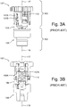
- Figs. 2 , 3A-3B , 4A-4B in the enclosed drawing are illustrating such a hand-held appliance known from the prior art.
- the known hand-held appliance 101 is shown in a condition in which the functional attachment 103 has been released from the main body 102 of the hand-held appliance 101.
- the shown hand-held appliance 101 is a shaving device, wherein the functional structure 105 of the functional attachment 103 comprises two hair-cutting units 105, only one of which is shown in Fig. 2 .
- the cross-sectional view of Fig. 2 further reveals at least the drive shaft 106, the coupling bush 108, the coupling head 109, the coupling spring 110, the driven part 107, and the pivot pin 127 for the driven part 107.
- the coupling structure 108, 109, 110 is in its uncoupled condition.
- Figs. 3A-3B show a side view and a cross-sectional view, respectively, of the coupling structure 108, 109, 110 together with the driven part 107.
- the driven part 107 is a gear wheel, wherein the connection collar 107A is an integrally manufactured part of the gear wheel.
- Figs. 4A-4B show the coupling structure 108, 109, 110 in a comparable, but more schematic cross-sectional view as compared to Fig. 3B .
- Figs. 4A-4B further show the drive shaft 106. It is noted that the coupling bush 108 is fixedly attached, via its connection collar 108A, to the drive shaft 106 in a co-rotatable manner about the rotation axis 116.
- the coupling spring 110 is held in-between the driven part 107 and the coupling head 109. Both the coupling head 109 and the coupling spring 110 are coupled to the driven part 107 in a co-rotatable manner about the rotation axis 117. These co-rotatabilities are realized in that the radial protrusions 109A of the coupling head 109 are extending into the axial slots 107B of the connection collar 107A of the driven part 107.
- Said axial slots 107B of the connection collar 107A, and said radial protrusions 109A of the coupling head 109, have the additional function to allow the coupling head 109 to axially displace relative to the driven part 107.
- the coupled condition of the known coupling structure 108, 109, 110 is shown in Figs. 3A-3B .
- the coupled condition of the coupling structure 108, 109, 110 requires that the functional attachment 102 (see Fig. 2 ) is attached to the main body 103 (see Fig. 2 ).
- the coupled condition of the coupling structure 108, 109, 110 additionally requires that the coupling head 109 is at least partly inserted via an axial end of the coupling bush 108 into an interior space of the coupling bush 108, while in said interior space there is co-rotating coupling between the coupling bush 108 and the coupling head 109.
- said co-rotating coupling in said interior space is realized in that the circumference of the outer side of the coupling head 109 has a polygonal shape, which mates with the polygonal shape of the circumference of the inner side of the coupling bush 108, as seen in cross-section transverse to the rotation axes 116, 117.
- Both Fig. 4A and Fig. 4B relate to a situation in which the functional attachment 102 is attached to the main body 103.
- the difference between the two figures, however, is that in Fig. 4A the coupling structure 108, 109, 110 is in the uncoupled condition, while in Fig. 4B it is in the coupled condition. That is, in Fig. 4A the coupling head 109 does not yet extend into the interior space of the coupling bush 108 for co-rotative coupling between the coupling bush 108 and the coupling head 109, due to misalignment of the abovementioned mating polygonal shapes of the coupling head 109 and the coupling bush 108. In fact, Fig.
- FIG. 4A relates to a situation immediately after a user has attached the functional attachment 102 to the main body 103, after which the motor has not yet been started to drive the drive shaft 106. As soon as the user starts the motor, said misalignment will automatically be cancelled under influence of the coupling spring 110, which urges displacement of the coupling head 109 into the interior space of the coupling bush 108, whereby the coupled condition shown in Fig. 4B is obtained.
- a drawback of this known hand-held appliance 101 is that its coupling structure is relatively spacious, especially in view of the relatively large axial length of the coupling structure 108, 109, 110.
- WO 2008/062339 A1 discloses a hand-held appliance, which is more or less similar to the above described known hand-held appliance 101. See WO 2008/062339 A1 , Fig. 5A , in which the reference numerals 4, 2, 22 are indicating parts which are similar to the main body 102, the functional attachment 103, and the coupling head 109, respectively, as described above. Fig. 5A of WO 2008/062339 A1 further shows a coupling spring similar to the coupling spring 110 described above. A corresponding coupling bush, however, is not explicitly shown in WO 2008/062339 A1 .
- the invention provides a hand-held appliance according to the appended independent claim 1.
- Preferable embodiments of the invention are provided by the appended dependent claims 2-5.
- the invention provides a hand-held appliance comprising a main body and a functional attachment, wherein:
- the hand-held appliance according to the invention differs from the known hand-held appliance of Figs. 2 , 3A-3B , 4A-4B in that for the hand-held appliance according to the invention:
- the coupling structure is more compact, especially in the axial direction of the coupling structure, and especially within the functional attachment of the hand-held appliance.
- said axial displaceability of the coupling bush relative to the drive shaft is realized in that the coupling bush and the drive shaft are interconnected in mutual telescoping engagement.
- the coupling bush and not the coupling head, is the axially displaceable part of the coupling structure, and the fact that the coupling bush is in said telescoping engagement with the drive shaft, together allow for a more compact structure to realize said axial displaceability for realizing the transition between the uncoupled condition and the coupled condition, and vice versa, as compared to the case wherein the coupling head would be in telescoping engagement with the driven part.
- the telescopic engagement of the coupling bush with the drive shaft and the fact that the coupling bush comprises the interior space for receiving the coupling head in said coupled condition of the coupling structure together result in a reduced overall dimension of the coupling structure in said coupled condition, as seen in an axial direction parallel to the rotational axes of the drive shaft and the driven part.
- the axially displaceable coupling bush allows for a reliable co-rotating coupling between the drive shaft and the coupling bush, on the one hand, and, simultaneously therewith, between the coupling bush and the coupling head, on the other hand.
- the telescoping engagement between the coupling bush and the drive shaft further contributes to obtaining compact overall dimensions of the coupling structure in combination with high reliability of the coupling structure.
- said second non-circular shape is the same as said third non-circular shape.
- the coupling head is an integrally manufactured part of the driven part.
- the hand-held appliance as shown in Figs. 1 , 5A-5B , 6A-6B , 7A-7B has all the features of all of the abovementioned main and preferable embodiments of the invention.
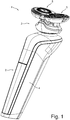
- Fig. 1 shows the hand-held appliance 1 in its attached condition, in which the functional attachment 3 is releasably attached to the main body 2.
- the shown hand-held appliance 1 is a shaving device, wherein the functional structure of the functional attachment 3 comprises two hair-cutting units 5.
- the coupling structure of the hand-held appliance 1 comprises the coupling bush 8, the coupling head 9 and the coupling spring 10.
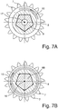
- FIG. 5A-5B , 6A-6B , 7A-7B show the coupling structure 8, 9, 10 in a comparable, but more schematic cross-sectional view as compared to Fig. 5B .
- the driven part 7 is a gear wheel, wherein the coupling head 9 is an integrally manufactured part of the gear wheel.
- the driven part 7 is rotatable about the rotation axis 17 in that the driven part 7 is rotatable about the pivot pin 27 (shown in Figs. 6A-6B ), whose center line functions as the rotation axis 17.
- the drive shaft 6 comprises the drive-shaft main-body 6A and the drive-shaft adapter 6B, which is fixedly attached to the drive-shaft main-body 6A in a co-rotatable manner about the rotation axis 16.
- the axial displaceability of the coupling bush 8 relative to the drive shaft 6 is realized in that the coupling bush 8 and the drive shaft 6 are interconnected in mutual telescoping engagement.
- the coupling spring 10 is held in-between a flange of the drive-shaft adapter 6B and a flange of the coupling bush 8. Both the coupling bush 8 and the coupling spring 10 are coupled to the drive shaft 6 in a co-rotatable manner about the rotation axis 16. These co-rotatabilities are realized in that the circumference of the outer side of the drive-shaft adapter 6B has a polygonal shape, which mates with the polygonal shape of the circumference of the inner side of the coupling bush 8, as seen in cross-section transverse to the rotation axis 16 (see Fig. 5B in combination with Fig. 7B ).
- the coupled condition of the coupling structure 8, 9, 10 requires that the functional attachment 2 is attached to the main body 3.
- the coupled condition of the coupling structure 8, 9, 10 additionally requires that the coupling head 9 is at least partly inserted via an axial end of the coupling bush 8 into an interior space of the coupling bush 8, while in said interior space there is co-rotating coupling between the coupling bush 8 and the coupling head 9.
- said co-rotating coupling in said interior space is realized in that the circumference of the outer side of the coupling head 9 has a polygonal shape, which mates with the polygonal shape of the circumference of the inner side of the coupling bush 8, as seen in cross-section transverse to the rotation axis 17 (see Fig. 5B in combination with Fig. 7A ).
- Figs. 5A-5B the coupling structure 8, 9, 10 is in its coupled condition. Both in Fig. 6A and in Fig. 6B the functional attachment 2 is attached to the main body 3.
- the difference between Fig. 6A and Fig. 6B is that in Fig. 6A the coupling structure 8, 9, 10 is in the uncoupled condition, while in Fig. 6B it is in the coupled condition. That is, in Fig. 6A the coupling head 9 does not yet extend into the interior space of the coupling bush 8 for co-rotating coupling between the coupling bush 8 and the coupling head 9, due to misalignment of the abovementioned mating polygonal shapes of the coupling head 9 and the coupling bush 8. In fact, Fig.
- FIG. 6A relates to a situation immediately after a user has attached the functional attachment 2 to the main body 3, after which the motor has not yet been started to drive the drive shaft 6.
- said misalignment will automatically be cancelled under influence of the coupling spring 10, which urges displacement of the coupling bush 8 towards the coupling head 9, so that the coupling head 9 will come to at least partly extend into the interior space of the coupling bush 8, whereby the coupled condition shown in Fig. 6B is obtained.
- the hand-held appliance 1 according to the invention differs from the known hand-held appliance 101 of Figs. 2 , 3A-3B , 4A-4B in that for the hand-held appliance 1 according to the invention:
Landscapes
- Life Sciences & Earth Sciences (AREA)
- Forests & Forestry (AREA)
- Engineering & Computer Science (AREA)
- Mechanical Engineering (AREA)
- Food-Manufacturing Devices (AREA)
- Dry Shavers And Clippers (AREA)
- Surgical Instruments (AREA)
- Telephone Set Structure (AREA)
Priority Applications (9)
| Application Number | Priority Date | Filing Date | Title |
|---|---|---|---|
| EP18201887.9A EP3643461A1 (de) | 2018-10-23 | 2018-10-23 | Handhaltbares gerät mit verbesserter koppelstruktur für eine funktionelle befestigung des gerätes |
| CN201980069865.4A CN112888538B (zh) | 2018-10-23 | 2019-10-14 | 具有用于器具的功能附件的改善型联接结构的手持式器具 |
| EP19783548.1A EP3870413B1 (de) | 2018-10-23 | 2019-10-14 | Handhaltbares gerät mit verbesserter koppelstruktur für eine funktionelle befestigung des gerätes |
| US17/278,458 US11833699B2 (en) | 2018-10-23 | 2019-10-14 | Hand-held appliance with improved coupling structure for a functional attachment of the appliance |
| KR1020217015021A KR20210079334A (ko) | 2018-10-23 | 2019-10-14 | 핸드헬드 기구의 기능성 부착물을 위한 개선된 결합 구조체를 갖는 핸드헬드 기구 |
| ES19783548T ES2913864T3 (es) | 2018-10-23 | 2019-10-14 | Aparato de mano con estructura de acoplamiento mejorada para una fijación funcional del aparato |
| JP2021520373A JP7008877B2 (ja) | 2018-10-23 | 2019-10-14 | ハンドヘルド器具の機能的アタッチメントのための改良されたカップリング構造を備えるハンドヘルド器具 |
| SG11202104039YA SG11202104039YA (en) | 2018-10-23 | 2019-10-14 | Hand-held appliance with improved coupling structure for a functional attachment of the appliance |
| PCT/EP2019/077675 WO2020083674A1 (en) | 2018-10-23 | 2019-10-14 | Hand-held appliance with improved coupling structure for a functional attachment of the appliance |
Applications Claiming Priority (1)
| Application Number | Priority Date | Filing Date | Title |
|---|---|---|---|
| EP18201887.9A EP3643461A1 (de) | 2018-10-23 | 2018-10-23 | Handhaltbares gerät mit verbesserter koppelstruktur für eine funktionelle befestigung des gerätes |
Publications (1)
| Publication Number | Publication Date |
|---|---|
| EP3643461A1 true EP3643461A1 (de) | 2020-04-29 |
Family
ID=63965300
Family Applications (2)
| Application Number | Title | Priority Date | Filing Date |
|---|---|---|---|
| EP18201887.9A Withdrawn EP3643461A1 (de) | 2018-10-23 | 2018-10-23 | Handhaltbares gerät mit verbesserter koppelstruktur für eine funktionelle befestigung des gerätes |
| EP19783548.1A Active EP3870413B1 (de) | 2018-10-23 | 2019-10-14 | Handhaltbares gerät mit verbesserter koppelstruktur für eine funktionelle befestigung des gerätes |
Family Applications After (1)
| Application Number | Title | Priority Date | Filing Date |
|---|---|---|---|
| EP19783548.1A Active EP3870413B1 (de) | 2018-10-23 | 2019-10-14 | Handhaltbares gerät mit verbesserter koppelstruktur für eine funktionelle befestigung des gerätes |
Country Status (8)
| Country | Link |
|---|---|
| US (1) | US11833699B2 (de) |
| EP (2) | EP3643461A1 (de) |
| JP (1) | JP7008877B2 (de) |
| KR (1) | KR20210079334A (de) |
| CN (1) | CN112888538B (de) |
| ES (1) | ES2913864T3 (de) |
| SG (1) | SG11202104039YA (de) |
| WO (1) | WO2020083674A1 (de) |
Cited By (4)
| Publication number | Priority date | Publication date | Assignee | Title |
|---|---|---|---|---|
| USD980527S1 (en) * | 2019-12-19 | 2023-03-07 | Koninklijke Philips N.V. | Shaver |
| EP4197722A1 (de) * | 2021-12-14 | 2023-06-21 | Koninklijke Philips N.V. | Lösbare elektrische verbindung in einer handgehaltenen körperpflegevorrichtung |
| USD994223S1 (en) * | 2018-02-27 | 2023-08-01 | Koninklijke Philips N.V. | Shaver |
| USD1006327S1 (en) * | 2018-05-04 | 2023-11-28 | Koninklijke Philips N.V. | Shaver |
Families Citing this family (3)
| Publication number | Priority date | Publication date | Assignee | Title |
|---|---|---|---|---|
| WO2018138302A1 (en) * | 2017-01-27 | 2018-08-02 | Koninklijke Philips N.V. | Shaving unit having cutting units with a flush hole for cleaning a hair collection chamber |
| EP3825078A1 (de) * | 2019-11-19 | 2021-05-26 | Koninklijke Philips N.V. | Rasiereinheit und elektrischer rasierer mit der rasiereinheit |
| CN114654508A (zh) * | 2022-04-21 | 2022-06-24 | 慈溪市金悦电子有限公司 | 一种剃须刀 |
Citations (4)
| Publication number | Priority date | Publication date | Assignee | Title |
|---|---|---|---|---|
| WO2004065078A1 (en) * | 2003-01-20 | 2004-08-05 | Koninklijke Philips Electronics N.V. | Shaving apparatus |
| US20070084059A1 (en) * | 2005-10-17 | 2007-04-19 | Hannan Jeremiah Jerry M | Oscillating triple head electric shaver |
| WO2008062339A1 (en) | 2006-11-20 | 2008-05-29 | Koninklijke Philips Electronics N.V. | Rotary shaver with improved support structure for shaving heads |
| US8230601B2 (en) * | 2008-06-27 | 2012-07-31 | Izumi Products Company | Rotary electric shaver |
Family Cites Families (39)
| Publication number | Priority date | Publication date | Assignee | Title |
|---|---|---|---|---|
| GB598664A (en) * | 1944-03-08 | 1948-02-24 | Hermann Konrad S A | Razor |
| US3447241A (en) * | 1967-01-13 | 1969-06-03 | Ernst Moeckl | Shutter for an electric razor having a cleaning function |
| DE2154974A1 (de) * | 1971-11-05 | 1973-05-10 | Braun Ag | Trockenrasierapparat mit rundscherkopf |
| NL7217486A (de) * | 1972-12-22 | 1974-06-25 | ||
| JPS5719084Y2 (de) * | 1976-05-26 | 1982-04-21 | ||
| NL7713043A (nl) * | 1977-11-28 | 1979-05-30 | Philips Nv | Scheerapparaat. |
| NL7713046A (nl) * | 1977-11-28 | 1979-05-30 | Philips Nv | Scheerapparaat. |
| NL7713044A (nl) * | 1977-11-28 | 1979-05-30 | Philips Nv | Scheerapparaat. |
| NL7809603A (nl) * | 1978-09-21 | 1980-03-25 | Philips Nv | Scheerapparaat. |
| NL7809604A (nl) * | 1978-09-21 | 1980-03-25 | Philips Nv | Scheerapparaat. |
| DE2852990C2 (de) * | 1978-12-07 | 1982-02-18 | Philips Patentverwaltung Gmbh, 2000 Hamburg | "Vormesser als Haarzugelement für Schermesser von elektrisch angetriebenen Trockenrasierapparaten" |
| JPS57106045A (en) | 1980-12-23 | 1982-07-01 | Mitsubishi Electric Corp | Semiconductor device |
| JPS5910767U (ja) * | 1982-07-13 | 1984-01-23 | セイコーエプソン株式会社 | 往復式電気かみそりの駆動装置 |
| NL8403065A (nl) * | 1984-10-09 | 1986-05-01 | Philips Nv | Scheerapparaat. |
| WO1989008524A1 (en) * | 1988-03-15 | 1989-09-21 | Robert Bosch Gmbh | Jigsaw |
| NL8900071A (nl) * | 1989-01-12 | 1990-08-01 | Philips Nv | Scheerapparaat. |
| DE9104026U1 (de) | 1991-04-03 | 1991-06-27 | Hsin, Liu, Taipeh/T'ai-pei | Drehmomentmechanismus für ein motorbetriebenes Werkzeug |
| US5504961A (en) * | 1994-08-16 | 1996-04-09 | Yang; C. S. | Electric toothbrush with drive release |
| JP2000505696A (ja) * | 1996-12-20 | 2000-05-16 | コーニンクレッカ フィリップス エレクトロニクス エヌ ヴィ | 髭剃り装置 |
| EP0918599B1 (de) * | 1997-02-19 | 2003-04-23 | Koninklijke Philips Electronics N.V. | Rasiergerät |
| US6219920B1 (en) * | 1998-03-31 | 2001-04-24 | Braun Gmbh | Dry shaving apparatus |
| JP4152317B2 (ja) * | 2001-07-30 | 2008-09-17 | コーニンクレッカ フィリップス エレクトロニクス エヌ ヴィ | 回転式ひげ剃り器の内側切断部材の連結 |
| US7067945B2 (en) * | 2002-05-03 | 2006-06-27 | Koninklijke Philips Electronics N.V. | Apparatus for converting side-to-side driving motion to rotational motion with a spring assembly and system for tuning the spring assembly |
| JP4960864B2 (ja) * | 2004-06-21 | 2012-06-27 | コーニンクレッカ フィリップス エレクトロニクス エヌ ヴィ | シェービング装置 |
| JP2006198093A (ja) * | 2005-01-19 | 2006-08-03 | Izumi Products Co | ロータリー式電気かみそり |
| JP2006218217A (ja) * | 2005-02-14 | 2006-08-24 | Izumi Products Co | ロータリー式電気かみそり |
| JP2006218219A (ja) * | 2005-02-14 | 2006-08-24 | Izumi Products Co | ロータリー式電気かみそり |
| JP2006223373A (ja) * | 2005-02-15 | 2006-08-31 | Izumi Products Co | ロータリー式電気かみそり |
| JP4756908B2 (ja) * | 2005-05-18 | 2011-08-24 | 株式会社泉精器製作所 | ロータリー式電気かみそり |
| JP4919255B2 (ja) * | 2005-10-25 | 2012-04-18 | 株式会社泉精器製作所 | ロータリー式電気かみそり |
| JP4969987B2 (ja) * | 2006-10-18 | 2012-07-04 | 株式会社泉精器製作所 | ロータリー式電気かみそり |
| JP5632832B2 (ja) * | 2008-05-27 | 2014-11-26 | コーニンクレッカ フィリップス エヌ ヴェ | 機能動作ユニットにおける電気エネルギーを生成するための手段を有する家庭用電気機器 |
| WO2014184065A1 (en) * | 2013-05-16 | 2014-11-20 | Koninklijke Philips N.V. | Shaving head with pivotable shaving unit |
| CN203458484U (zh) | 2013-07-22 | 2014-03-05 | 杭州博达设计咨询有限公司 | 电动牙刷的自动插接结构 |
| EP3131713B1 (de) * | 2014-04-18 | 2018-06-13 | Koninklijke Philips N.V. | Kupplungsmechanismus für einen antriebsstrang einer haarschneidemaschine |
| JP6688049B2 (ja) * | 2015-11-24 | 2020-04-28 | マクセルイズミ株式会社 | ロータリー式電気かみそりおよびロータリー式電気かみそりの内刃の製造方法 |
| US10850408B2 (en) * | 2016-06-21 | 2020-12-01 | Koninklijke Philips N.V. | Shaving apparatus with detachable cutting unit |
| WO2018138302A1 (en) * | 2017-01-27 | 2018-08-02 | Koninklijke Philips N.V. | Shaving unit having cutting units with a flush hole for cleaning a hair collection chamber |
| US10668634B2 (en) * | 2018-09-24 | 2020-06-02 | Conair Corporation | Oscillating rotary shaver |
-
2018
- 2018-10-23 EP EP18201887.9A patent/EP3643461A1/de not_active Withdrawn
-
2019
- 2019-10-14 SG SG11202104039YA patent/SG11202104039YA/en unknown
- 2019-10-14 JP JP2021520373A patent/JP7008877B2/ja not_active Expired - Fee Related
- 2019-10-14 WO PCT/EP2019/077675 patent/WO2020083674A1/en not_active Ceased
- 2019-10-14 EP EP19783548.1A patent/EP3870413B1/de active Active
- 2019-10-14 US US17/278,458 patent/US11833699B2/en active Active
- 2019-10-14 ES ES19783548T patent/ES2913864T3/es active Active
- 2019-10-14 KR KR1020217015021A patent/KR20210079334A/ko not_active Withdrawn
- 2019-10-14 CN CN201980069865.4A patent/CN112888538B/zh active Active
Patent Citations (4)
| Publication number | Priority date | Publication date | Assignee | Title |
|---|---|---|---|---|
| WO2004065078A1 (en) * | 2003-01-20 | 2004-08-05 | Koninklijke Philips Electronics N.V. | Shaving apparatus |
| US20070084059A1 (en) * | 2005-10-17 | 2007-04-19 | Hannan Jeremiah Jerry M | Oscillating triple head electric shaver |
| WO2008062339A1 (en) | 2006-11-20 | 2008-05-29 | Koninklijke Philips Electronics N.V. | Rotary shaver with improved support structure for shaving heads |
| US8230601B2 (en) * | 2008-06-27 | 2012-07-31 | Izumi Products Company | Rotary electric shaver |
Cited By (6)
| Publication number | Priority date | Publication date | Assignee | Title |
|---|---|---|---|---|
| USD994223S1 (en) * | 2018-02-27 | 2023-08-01 | Koninklijke Philips N.V. | Shaver |
| USD1006327S1 (en) * | 2018-05-04 | 2023-11-28 | Koninklijke Philips N.V. | Shaver |
| USD980527S1 (en) * | 2019-12-19 | 2023-03-07 | Koninklijke Philips N.V. | Shaver |
| EP4197722A1 (de) * | 2021-12-14 | 2023-06-21 | Koninklijke Philips N.V. | Lösbare elektrische verbindung in einer handgehaltenen körperpflegevorrichtung |
| WO2023110416A1 (en) * | 2021-12-14 | 2023-06-22 | Koninklijke Philips N.V. | Releasable electric connection in a handheld personal care device |
| JP2024544261A (ja) * | 2021-12-14 | 2024-11-28 | コーニンクレッカ フィリップス エヌ ヴェ | ハンドヘルドパーソナルケアデバイスにおける解放可能な電気接続 |
Also Published As
| Publication number | Publication date |
|---|---|
| ES2913864T3 (es) | 2022-06-06 |
| WO2020083674A1 (en) | 2020-04-30 |
| JP2021533948A (ja) | 2021-12-09 |
| EP3870413B1 (de) | 2022-03-23 |
| US11833699B2 (en) | 2023-12-05 |
| KR20210079334A (ko) | 2021-06-29 |
| JP7008877B2 (ja) | 2022-01-25 |
| CN112888538A (zh) | 2021-06-01 |
| EP3870413A1 (de) | 2021-09-01 |
| CN112888538B (zh) | 2022-12-02 |
| US20210347074A1 (en) | 2021-11-11 |
| SG11202104039YA (en) | 2021-05-28 |
Similar Documents
| Publication | Publication Date | Title |
|---|---|---|
| EP3870413B1 (de) | Handhaltbares gerät mit verbesserter koppelstruktur für eine funktionelle befestigung des gerätes | |
| US20020105217A1 (en) | Fixing device for a removable armrest, and a seat device including such a fixing device | |
| JP6450239B2 (ja) | 車両用電動格納式視認装置 | |
| US10098637B2 (en) | Adapter assembly for interconnecting electromechanical surgical devices and surgical loading units, and surgical systems thereof | |
| EP2510773A1 (de) | Rasenmäher und schutzabdeckung dafür | |
| JPH07314216A (ja) | ドリル/チゼル装置 | |
| US20110107536A1 (en) | Brushhead assembly for a power toothbrush | |
| CN205057974U (zh) | 手持式工具机 | |
| JP2001524331A (ja) | 電動歯ブラシ用ブラシセクション | |
| JP2006522705A (ja) | 自動車の風防ガラスワイパ装置を組み立てる方法および構造 | |
| JP6421155B2 (ja) | ギヤドモータ | |
| US20070100362A1 (en) | Powered surgical handpiece with improved latch mechanism and rotary to oscillating output drive | |
| US5410921A (en) | Universal window-actuator drive unit | |
| US7201081B2 (en) | Bowden cable with a curved guide part | |
| EP3643460A1 (de) | Verbesserte haarschneideeinheit | |
| US8689390B2 (en) | Wiper device | |
| EP3626415A1 (de) | Verbesserte haarschneideeinheit für einen rasierapparat | |
| JP2001505850A (ja) | ウィンドガラスワイパ | |
| HK40044042A (en) | Hand-held appliance with improved coupling structure for a functional attachment of the appliance | |
| HK40044042B (en) | Hand-held appliance with improved coupling structure for a functional attachment of the appliance | |
| JP2002345844A (ja) | 歯科用ハンドピース | |
| RU2782399C1 (ru) | Ручное устройство с усовершенствованной соединительной конструкцией для функциональной насадки указанного устройства | |
| CN216008984U (zh) | 摇头机构及风扇 | |
| US6962489B2 (en) | Moineau pumping device having a ball coupling | |
| CN210990372U (zh) | 一种超声微探头连接器 |
Legal Events
| Date | Code | Title | Description |
|---|---|---|---|
| PUAI | Public reference made under article 153(3) epc to a published international application that has entered the european phase |
Free format text: ORIGINAL CODE: 0009012 |
|
| STAA | Information on the status of an ep patent application or granted ep patent |
Free format text: STATUS: THE APPLICATION HAS BEEN PUBLISHED |
|
| AK | Designated contracting states |
Kind code of ref document: A1 Designated state(s): AL AT BE BG CH CY CZ DE DK EE ES FI FR GB GR HR HU IE IS IT LI LT LU LV MC MK MT NL NO PL PT RO RS SE SI SK SM TR |
|
| AX | Request for extension of the european patent |
Extension state: BA ME |
|
| STAA | Information on the status of an ep patent application or granted ep patent |
Free format text: STATUS: THE APPLICATION IS DEEMED TO BE WITHDRAWN |
|
| 18D | Application deemed to be withdrawn |
Effective date: 20201030 |