EP3643565A1 - Dispositif, système et procédé de fixation d'une charge dans un véhicule - Google Patents
Dispositif, système et procédé de fixation d'une charge dans un véhicule Download PDFInfo
- Publication number
- EP3643565A1 EP3643565A1 EP19193517.0A EP19193517A EP3643565A1 EP 3643565 A1 EP3643565 A1 EP 3643565A1 EP 19193517 A EP19193517 A EP 19193517A EP 3643565 A1 EP3643565 A1 EP 3643565A1
- Authority
- EP
- European Patent Office
- Prior art keywords
- rail
- counter bearing
- latching elements
- locking
- elements
- Prior art date
- Legal status (The legal status is an assumption and is not a legal conclusion. Google has not performed a legal analysis and makes no representation as to the accuracy of the status listed.)
- Granted
Links
Images




Classifications
-
- B—PERFORMING OPERATIONS; TRANSPORTING
- B60—VEHICLES IN GENERAL
- B60P—VEHICLES ADAPTED FOR LOAD TRANSPORTATION OR TO TRANSPORT, TO CARRY, OR TO COMPRISE SPECIAL LOADS OR OBJECTS
- B60P7/00—Securing or covering of load on vehicles
- B60P7/06—Securing of load
- B60P7/08—Securing to the vehicle floor or sides
- B60P7/0807—Attachment points
- B60P7/0815—Attachment rails or trellis
-
- B—PERFORMING OPERATIONS; TRANSPORTING
- B60—VEHICLES IN GENERAL
- B60P—VEHICLES ADAPTED FOR LOAD TRANSPORTATION OR TO TRANSPORT, TO CARRY, OR TO COMPRISE SPECIAL LOADS OR OBJECTS
- B60P7/00—Securing or covering of load on vehicles
- B60P7/06—Securing of load
- B60P7/08—Securing to the vehicle floor or sides
- B60P7/0807—Attachment points
Definitions
- the invention relates to a device, a system and a method according to the independent claims.
- the DE 10 2014 109 311 A1 discloses, for example, a lashing eye which can be arranged displaceably and locked in a loading space rail of a motor vehicle.
- the lashing eye comprises a locking element, which can be released via an operating button.
- the object of the present invention is to overcome the disadvantages of the prior art.
- a device for securing a load in a vehicle comprises a base body, a load connection element and at least two latching elements and an actuating section.
- the latching elements each comprise at least one convex section.
- the locking elements are arranged so that they are relative to the base body can move horizontally and reversibly between a retracted and an extended position.
- the device further comprises a counter bearing, which is arranged such that it can move vertically and reversibly relative to the base body between a lowered and a raised position.
- the counter bearing is also set up to come into contact with the convex sections.
- the device is set up so that actuation of the actuating section moves the counter bearing into the lowered position, the counter bearing interacting with the convex sections of the latching elements during a downward movement in such a way that the latching elements are moved into the retracted position.
- the locking elements are also biased towards the extended position, so that the convex portions of the locking elements move the counter bearing in the raised position in the absence of actuation.
- the connecting element can be an eyelet, for example.
- the actuating section is preferably actuated by pressing it down.
- the locking elements can each comprise at least one locking lug.
- the locking elements can also each comprise two, three or more locking lugs.
- the locking lugs are preferably designed so that they can move into locking recesses in a rail receiving the device.
- the counter bearing and the actuating section can be formed in one piece.
- One piece here means that the counter bearing and the actuating section are components of a single component which takes on both the function of the actuating section and the function of the counter bearing.
- the base body can comprise a central recess in which the counter bearing, the actuating section and the latching elements are arranged in the operating position, wherein the counter bearing and the actuating section can be fixed separately or together in at least one guide device in a complementary guide.
- the counter bearing is preferably an angular counter bearing.
- the guide device can be, for example, a pin or the like.
- the complementary guide can be, for example, a groove in which the pin is movably guided.
- the present invention further comprises a system for securing a load in a vehicle, comprising a device as described above and a rail, the rail comprising latching recesses which are designed to be complementary to the latching elements. If latching lugs are present on the latching elements, the latching recesses are preferably designed to be complementary to the latching lugs.
- the rail preferably has projections or undercuts. In the extended position, the latching elements can travel under these projections or undercuts in such a way that a positive fit that arises prevents the device from being removed from the rail.
- a sliding along the rail is prevented by the locking elements or locking lugs inserted into the locking recesses.
- a section of the device that can be lowered into the rail can have axis symmetry. At least the part of the device that can be lowered into the rail is therefore preferably axisymmetric.
- the rail has locking recesses on only one side and is formed on the opposite side as an abutment without locking recesses.
- one of the locking elements or one or more locking lugs
- the opposite locking element or the opposite locking lugs
- This support results in an advantageous rattle protection, because the device is secured on the one hand against displacement along the rail and against removal from the rail and on the other hand a play of the device within the rail is severely restricted or even completely eliminated.
- mutually facing sections of the locking elements or locking lugs and the abutment can be designed to be complementary to one another.
- a concave section of a latching lug can be opposed, for example, by a complementary, convex abutment.
- the rail preferably comprises projections which preferably partially overlap an interior of the rail. These projections preferably also provide support surfaces on which support sections of the device can be placed.
- latching elements or latching lugs can preferably not only move into the corresponding latching recesses in the interior of the rail, in order to face the device within the rail a shift along the rail. Rather, the locking elements preferably move out of the base body and into a space below the projections of the rail in such a way that the device is also secured against being removed from the rail upwards.
- the device can be operated with only one hand, since both the insertion of the device into the rail and also the actuation, in particular pressing down, of the actuating element can take place with only one hand.
- the pre-tensioning to the extended position can be carried out with the aid of one, preferably two or more springs, which, via the operative connection of the convex sections with the counter bearing, both pre-tension the locking elements into the extended position and pre-tensioning the actuating section and the counter-bearing in the effect raised position.
- the axis symmetry ensures that a rotation of 180 ° does not affect the insertion into the rail or the function of the system. This avoids errors when setting the device in the rail.
- the device is set up in such a way that it only has to be introduced into the rail and, where appropriate, has to be moved a little along the rail in order to engage. This enables a very secure fixing of the device within the rail.
- the operation of the inventive device is explained as follows:
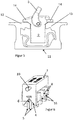
- the in the Figures 6 and 8th elements shown are in the operating position, which for example in Figure 3 is shown in the interior of the base body 2.
- the actuating section 7, which is formed in one piece with the angular counter bearing 4 is guided via the guide devices 10 in the form of two bolts in a groove (not shown) or the like, which is perpendicular to the central recess 9 of the base body 2 runs.
- the angular counter bearing 4 and the actuating section 7 can therefore move reversibly within the base body 2 between a raised and a lowered position, which is a comparison of the Figures 1 and 2nd as well as the Figures 2 and 3rd emerges.
- the in Figure 6 shown arrangement of the lowered position, while the arrangement after Figure 8 corresponds to the raised position.
- the locking elements 5 are in the operating position within the base body 2, wherein the three locking lugs 8 can protrude through the through openings 17, which in the Figures 1 and 7 is recognizable.
- Figure 5 shows a corresponding arrangement with retracted locking elements 5 and locking lugs 8.
- the locking elements 5 can thus move horizontally towards and away from each other.
- the locking lugs 8 can accordingly move into the base body 2 or move outwards through the passage openings 17.
- the horizontal movement of the locking elements 5 is restricted here by their arrangement within the base body 2.
- the latching elements 5 comprise two sliding recesses 18 which are attached to two guide pins 16 in the operating position.
- the guide bolts 16 are fixed within the base body 2 in corresponding passage openings 17.
- the latching elements 5 can therefore move horizontally within the base body 2 along the guide bolts 16 which pass through the sliding recesses 18 in the operating position.
- the springs 15 in Figure 8 only one of these springs 15 can be seen due to the perspective
- the springs 15 ensure that the latching elements 5 in the direction of the extended position (shown in FIGS Figures 7 and 8 ) are biased.
- the springs 15 thus provide a bias, which ensures that the locking elements 5 slide apart.
- the locking elements 5 are then moved towards each other against a biasing force of the springs 15 when the angular counter bearing 4 is moved into a lowered position.
- sections of the angular counter bearing 4 press on the convex sections 6, so that there is preferably a tangential line of contact between the touching sections of the angular counter bearing 4 and the convex sections 6.
- a tangential line of contact instead of, for example, a contact surface, which would result from two opposing sheet-like sections, is provided by the interaction of the convex section 6 with the flat or planar section of the counter bearing 4.
- a convex surface and a flat surface can generally not form a contacting surface section, there is only a line of contact in the form of a tangent of the convex section 6 on the section of the thrust bearing 4. This effectively prevents the thrust bearing 4 and the convex section 6 from getting caught, because in the case of a line of contact, significantly less friction occurs as in the case of touching surfaces (sections).
- a downward movement of the actuating section 7 and the angular counter bearing 4 in the direction of an arrow 19 thus leads to a movement of the latching elements towards one another along the directions of the arrows 20.
- the user can press the actuating section 7 with one or more fingers in order to move it into the lowered position.
- the load connection element 3 serves to connect any load and to fix it, for example on the floor of a vehicle, in which the rail 11 can be embedded.
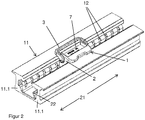
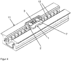
- the device 1 is fixed in the manner shown in FIGS Figures 1 to 4 is shown.
- the load connection element 3 can already be connected to a load.
- such a load is not shown for the sake of clarity.
- the device 1 is first inserted into the rail 11, which the Figures 1 and 2nd can be seen.
- the actuating element 7 must be lowered for insertion in order to move the locking lugs 8 into the retracted position before insertion.
- the system is preferably designed in such a way that when the device 1 is introduced into the interior of the rail 11 when the projections 13 pass through it, the latching lugs 8 are pressed a little inward thereof without the user having to press the actuating section 7 downward. A simple one-handed insertion is thus possible by simply pressing the device 1 into the rail 11 under slight pressure.
- the former immediately move into the latter. If this is not the case, the device 1 can be moved a little way along the rail 11, i.e. in one of the directions, which are indicated by an arrow 21. As soon as locking lugs 8 and locking recesses 12 are correspondingly opposite one another and no pressure is exerted on the actuating element 7, the locking lugs 8 move into the locking recesses 12 due to the spring force of the springs 15.
- the rail 11 consists of two sub-rails 11.1, 11.2.
- the inner part rail 11.2 lies within the outer part rail 11.1.
- the inner part rail 11.2 can for example be screwed to the outer part rail 11.1.
- the inner part of the rail 11.2 provides the abutment 22 and the locking recesses 12.
- the latching recesses are located on the side of the partial rail 11.2 opposite the abutment 22 and are shown in FIG Figure 7 not visible.
- Both sub-rails 11.1, 11.2 can be produced in a simple manner, for example as extruded profiles, and then connected to one another.
- the spring 15 can also be replaced by another energy storage element.
Landscapes
- Engineering & Computer Science (AREA)
- Transportation (AREA)
- Mechanical Engineering (AREA)
- Fittings On The Vehicle Exterior For Carrying Loads, And Devices For Holding Or Mounting Articles (AREA)
- Vehicle Step Arrangements And Article Storage (AREA)
- Seats For Vehicles (AREA)
Applications Claiming Priority (1)
| Application Number | Priority Date | Filing Date | Title |
|---|---|---|---|
| DE102018123734.0A DE102018123734B4 (de) | 2018-09-26 | 2018-09-26 | Vorrichtung, System und Verfahren zum Sichern einer Last in einem Fahrzeug |
Publications (2)
| Publication Number | Publication Date |
|---|---|
| EP3643565A1 true EP3643565A1 (fr) | 2020-04-29 |
| EP3643565B1 EP3643565B1 (fr) | 2021-06-30 |
Family
ID=67766037
Family Applications (1)
| Application Number | Title | Priority Date | Filing Date |
|---|---|---|---|
| EP19193517.0A Active EP3643565B1 (fr) | 2018-09-26 | 2019-08-26 | Dispositif, système et procédé de fixation d'une charge dans un véhicule |
Country Status (2)
| Country | Link |
|---|---|
| EP (1) | EP3643565B1 (fr) |
| DE (1) | DE102018123734B4 (fr) |
Families Citing this family (2)
| Publication number | Priority date | Publication date | Assignee | Title |
|---|---|---|---|---|
| DE102018126380B4 (de) | 2018-10-23 | 2021-09-16 | Kipp Gmbh & Co Kg | Lastaufnahmevorrichtung und Lastaufnahmesystem |
| US20230056731A1 (en) * | 2021-08-23 | 2023-02-23 | Indiev, Inc | Modular cargo storage system for passenger vehicle |
Citations (4)
| Publication number | Priority date | Publication date | Assignee | Title |
|---|---|---|---|---|
| DE102005061493A1 (de) | 2005-12-22 | 2007-07-05 | Kipp Gmbh & Co. Kg Cargo & Safety Systems | Gepäckhalteeinrichtung |
| DE102007018254A1 (de) * | 2007-04-13 | 2008-10-16 | Bos Gmbh & Co. Kg | Vorrichtung zum Befestigen von Ladegut in einem Transportmittel |
| DE102012221386A1 (de) * | 2012-11-22 | 2014-05-22 | Kipp Gmbh & Co. Kg | Gepäckhalteeinrichtung, insbesondere Lastöse, zum Verfahren und Verrasten in einer Lastschiene |
| DE102014109311A1 (de) | 2014-07-03 | 2016-01-07 | Lenz, Kämper GmbH & Co. KG | Verzurröse zur verschiebbaren und arretierbaren Anordnung an einer Laderaumschiene eines Kraftfahrzeugs |
Family Cites Families (1)
| Publication number | Priority date | Publication date | Assignee | Title |
|---|---|---|---|---|
| DE202005002568U1 (de) | 2005-02-16 | 2005-04-14 | Lenz, Kämper GmbH & Co. KG | Lastöse für den Laderaum eines Kraftfahrzeuges |
-
2018
- 2018-09-26 DE DE102018123734.0A patent/DE102018123734B4/de not_active Expired - Fee Related
-
2019
- 2019-08-26 EP EP19193517.0A patent/EP3643565B1/fr active Active
Patent Citations (4)
| Publication number | Priority date | Publication date | Assignee | Title |
|---|---|---|---|---|
| DE102005061493A1 (de) | 2005-12-22 | 2007-07-05 | Kipp Gmbh & Co. Kg Cargo & Safety Systems | Gepäckhalteeinrichtung |
| DE102007018254A1 (de) * | 2007-04-13 | 2008-10-16 | Bos Gmbh & Co. Kg | Vorrichtung zum Befestigen von Ladegut in einem Transportmittel |
| DE102012221386A1 (de) * | 2012-11-22 | 2014-05-22 | Kipp Gmbh & Co. Kg | Gepäckhalteeinrichtung, insbesondere Lastöse, zum Verfahren und Verrasten in einer Lastschiene |
| DE102014109311A1 (de) | 2014-07-03 | 2016-01-07 | Lenz, Kämper GmbH & Co. KG | Verzurröse zur verschiebbaren und arretierbaren Anordnung an einer Laderaumschiene eines Kraftfahrzeugs |
Also Published As
| Publication number | Publication date |
|---|---|
| EP3643565B1 (fr) | 2021-06-30 |
| DE102018123734A1 (de) | 2020-03-26 |
| DE102018123734B4 (de) | 2020-07-02 |
Similar Documents
| Publication | Publication Date | Title |
|---|---|---|
| EP0049758B1 (fr) | Dispositif pour régler graduellement la distance entre deux parties de chaise | |
| DE102010039157A1 (de) | Schienenlängsführung | |
| DE2254181C3 (de) | Betätigungseinrichtung für die bewegbare Innenscheibe einer Schiebefensteranordnung, insbesondere bei Kraftfahrzeugen | |
| EP3010665B1 (fr) | Outil de pliage | |
| EP3643565B1 (fr) | Dispositif, système et procédé de fixation d'une charge dans un véhicule | |
| WO2017016844A1 (fr) | Système de fixation, corps de clip et clip | |
| EP3597073A1 (fr) | Dispositif table monté résistant aux chocs | |
| DE102013100275A1 (de) | Treibriegelschloss mit überdrückbarem Riegelschieber | |
| DE102012018590A1 (de) | Spritz- oder Druckgusswerkzeug mit Plattenarretierung | |
| DE102016119490A1 (de) | Sitzschienenanordnung | |
| DE102013021404A1 (de) | Kupplungssystem | |
| EP3474305B1 (fr) | Commutateur de sécurité | |
| EP3636104A2 (fr) | Dispositif d'accouplement pour le guidage de coulisse | |
| DE102019120902A1 (de) | Befestigungssystem eines Sitzes und zugeordnetes Fluggerät | |
| DE69313577T2 (de) | Verbesserung an Türgriffen mit einer plattenförmigen Handhabe | |
| DE19742636C2 (de) | Türsicherung | |
| DE3243550A1 (de) | Verbindungsvorrichtung fuer einen einem verstellbaren fahrzeugsitz zugeordneten sicherheitsgurt | |
| DE102011008297A1 (de) | Vorrichtung zum Trennen beweglicher Körper | |
| DE102014004076B4 (de) | Spritzgussmaschine mit Sicherheitstür | |
| EP3819422A1 (fr) | Articulation et séchoir à linge doté d'une telle articulation | |
| EP3860402B1 (fr) | Dispositif de fixation servant à fixer un panneau d'un tiroir sur un châssis | |
| DE102023130090A1 (de) | Schubkasten mit einer Einstellvorrichtung zur Seitenverstellung der Blende | |
| DE3513028C2 (de) | Fassung zur Halterung einer Vielzahl von Anschlußstiften | |
| DE2208867A1 (de) | Sitzanordnung mit mitteln zur arretierung der in ihrer neigung verstellbaren rueckenlehne, insbesondere fuer ein kraftfahrzeug | |
| DE102024123716A1 (de) | Vorrichtung zur Absorption von Energie während eines Crashfalls |
Legal Events
| Date | Code | Title | Description |
|---|---|---|---|
| PUAI | Public reference made under article 153(3) epc to a published international application that has entered the european phase |
Free format text: ORIGINAL CODE: 0009012 |
|
| STAA | Information on the status of an ep patent application or granted ep patent |
Free format text: STATUS: THE APPLICATION HAS BEEN PUBLISHED |
|
| AK | Designated contracting states |
Kind code of ref document: A1 Designated state(s): AL AT BE BG CH CY CZ DE DK EE ES FI FR GB GR HR HU IE IS IT LI LT LU LV MC MK MT NL NO PL PT RO RS SE SI SK SM TR |
|
| AX | Request for extension of the european patent |
Extension state: BA ME |
|
| STAA | Information on the status of an ep patent application or granted ep patent |
Free format text: STATUS: REQUEST FOR EXAMINATION WAS MADE |
|
| 17P | Request for examination filed |
Effective date: 20201012 |
|
| RBV | Designated contracting states (corrected) |
Designated state(s): AL AT BE BG CH CY CZ DE DK EE ES FI FR GB GR HR HU IE IS IT LI LT LU LV MC MK MT NL NO PL PT RO RS SE SI SK SM TR |
|
| RIC1 | Information provided on ipc code assigned before grant |
Ipc: B60P 7/08 20060101AFI20201217BHEP |
|
| GRAP | Despatch of communication of intention to grant a patent |
Free format text: ORIGINAL CODE: EPIDOSNIGR1 |
|
| STAA | Information on the status of an ep patent application or granted ep patent |
Free format text: STATUS: GRANT OF PATENT IS INTENDED |
|
| INTG | Intention to grant announced |
Effective date: 20210201 |
|
| GRAS | Grant fee paid |
Free format text: ORIGINAL CODE: EPIDOSNIGR3 |
|
| GRAA | (expected) grant |
Free format text: ORIGINAL CODE: 0009210 |
|
| STAA | Information on the status of an ep patent application or granted ep patent |
Free format text: STATUS: THE PATENT HAS BEEN GRANTED |
|
| AK | Designated contracting states |
Kind code of ref document: B1 Designated state(s): AL AT BE BG CH CY CZ DE DK EE ES FI FR GB GR HR HU IE IS IT LI LT LU LV MC MK MT NL NO PL PT RO RS SE SI SK SM TR |
|
| REG | Reference to a national code |
Ref country code: CH Ref legal event code: EP |
|
| REG | Reference to a national code |
Ref country code: DE Ref legal event code: R096 Ref document number: 502019001711 Country of ref document: DE Ref country code: AT Ref legal event code: REF Ref document number: 1406073 Country of ref document: AT Kind code of ref document: T Effective date: 20210715 |
|
| REG | Reference to a national code |
Ref country code: IE Ref legal event code: FG4D Free format text: LANGUAGE OF EP DOCUMENT: GERMAN |
|
| REG | Reference to a national code |
Ref country code: LT Ref legal event code: MG9D |
|
| PG25 | Lapsed in a contracting state [announced via postgrant information from national office to epo] |
Ref country code: FI Free format text: LAPSE BECAUSE OF FAILURE TO SUBMIT A TRANSLATION OF THE DESCRIPTION OR TO PAY THE FEE WITHIN THE PRESCRIBED TIME-LIMIT Effective date: 20210630 Ref country code: HR Free format text: LAPSE BECAUSE OF FAILURE TO SUBMIT A TRANSLATION OF THE DESCRIPTION OR TO PAY THE FEE WITHIN THE PRESCRIBED TIME-LIMIT Effective date: 20210630 Ref country code: BG Free format text: LAPSE BECAUSE OF FAILURE TO SUBMIT A TRANSLATION OF THE DESCRIPTION OR TO PAY THE FEE WITHIN THE PRESCRIBED TIME-LIMIT Effective date: 20210930 |
|
| REG | Reference to a national code |
Ref country code: NL Ref legal event code: MP Effective date: 20210630 |
|
| PG25 | Lapsed in a contracting state [announced via postgrant information from national office to epo] |
Ref country code: SE Free format text: LAPSE BECAUSE OF FAILURE TO SUBMIT A TRANSLATION OF THE DESCRIPTION OR TO PAY THE FEE WITHIN THE PRESCRIBED TIME-LIMIT Effective date: 20210630 Ref country code: RS Free format text: LAPSE BECAUSE OF FAILURE TO SUBMIT A TRANSLATION OF THE DESCRIPTION OR TO PAY THE FEE WITHIN THE PRESCRIBED TIME-LIMIT Effective date: 20210630 Ref country code: NO Free format text: LAPSE BECAUSE OF FAILURE TO SUBMIT A TRANSLATION OF THE DESCRIPTION OR TO PAY THE FEE WITHIN THE PRESCRIBED TIME-LIMIT Effective date: 20210930 Ref country code: LV Free format text: LAPSE BECAUSE OF FAILURE TO SUBMIT A TRANSLATION OF THE DESCRIPTION OR TO PAY THE FEE WITHIN THE PRESCRIBED TIME-LIMIT Effective date: 20210630 Ref country code: GR Free format text: LAPSE BECAUSE OF FAILURE TO SUBMIT A TRANSLATION OF THE DESCRIPTION OR TO PAY THE FEE WITHIN THE PRESCRIBED TIME-LIMIT Effective date: 20211001 |
|
| PG25 | Lapsed in a contracting state [announced via postgrant information from national office to epo] |
Ref country code: EE Free format text: LAPSE BECAUSE OF FAILURE TO SUBMIT A TRANSLATION OF THE DESCRIPTION OR TO PAY THE FEE WITHIN THE PRESCRIBED TIME-LIMIT Effective date: 20210630 Ref country code: ES Free format text: LAPSE BECAUSE OF FAILURE TO SUBMIT A TRANSLATION OF THE DESCRIPTION OR TO PAY THE FEE WITHIN THE PRESCRIBED TIME-LIMIT Effective date: 20210630 Ref country code: SK Free format text: LAPSE BECAUSE OF FAILURE TO SUBMIT A TRANSLATION OF THE DESCRIPTION OR TO PAY THE FEE WITHIN THE PRESCRIBED TIME-LIMIT Effective date: 20210630 Ref country code: CZ Free format text: LAPSE BECAUSE OF FAILURE TO SUBMIT A TRANSLATION OF THE DESCRIPTION OR TO PAY THE FEE WITHIN THE PRESCRIBED TIME-LIMIT Effective date: 20210630 Ref country code: RO Free format text: LAPSE BECAUSE OF FAILURE TO SUBMIT A TRANSLATION OF THE DESCRIPTION OR TO PAY THE FEE WITHIN THE PRESCRIBED TIME-LIMIT Effective date: 20210630 Ref country code: NL Free format text: LAPSE BECAUSE OF FAILURE TO SUBMIT A TRANSLATION OF THE DESCRIPTION OR TO PAY THE FEE WITHIN THE PRESCRIBED TIME-LIMIT Effective date: 20210630 Ref country code: PT Free format text: LAPSE BECAUSE OF FAILURE TO SUBMIT A TRANSLATION OF THE DESCRIPTION OR TO PAY THE FEE WITHIN THE PRESCRIBED TIME-LIMIT Effective date: 20211102 Ref country code: SM Free format text: LAPSE BECAUSE OF FAILURE TO SUBMIT A TRANSLATION OF THE DESCRIPTION OR TO PAY THE FEE WITHIN THE PRESCRIBED TIME-LIMIT Effective date: 20210630 |
|
| PG25 | Lapsed in a contracting state [announced via postgrant information from national office to epo] |
Ref country code: PL Free format text: LAPSE BECAUSE OF FAILURE TO SUBMIT A TRANSLATION OF THE DESCRIPTION OR TO PAY THE FEE WITHIN THE PRESCRIBED TIME-LIMIT Effective date: 20210630 |
|
| REG | Reference to a national code |
Ref country code: DE Ref legal event code: R097 Ref document number: 502019001711 Country of ref document: DE |
|
| PG25 | Lapsed in a contracting state [announced via postgrant information from national office to epo] |
Ref country code: MC Free format text: LAPSE BECAUSE OF FAILURE TO SUBMIT A TRANSLATION OF THE DESCRIPTION OR TO PAY THE FEE WITHIN THE PRESCRIBED TIME-LIMIT Effective date: 20210630 |
|
| REG | Reference to a national code |
Ref country code: BE Ref legal event code: MM Effective date: 20210831 |
|
| PG25 | Lapsed in a contracting state [announced via postgrant information from national office to epo] |
Ref country code: DK Free format text: LAPSE BECAUSE OF FAILURE TO SUBMIT A TRANSLATION OF THE DESCRIPTION OR TO PAY THE FEE WITHIN THE PRESCRIBED TIME-LIMIT Effective date: 20210630 |
|
| PLBE | No opposition filed within time limit |
Free format text: ORIGINAL CODE: 0009261 |
|
| STAA | Information on the status of an ep patent application or granted ep patent |
Free format text: STATUS: NO OPPOSITION FILED WITHIN TIME LIMIT |
|
| PG25 | Lapsed in a contracting state [announced via postgrant information from national office to epo] |
Ref country code: LU Free format text: LAPSE BECAUSE OF NON-PAYMENT OF DUE FEES Effective date: 20210826 Ref country code: AL Free format text: LAPSE BECAUSE OF FAILURE TO SUBMIT A TRANSLATION OF THE DESCRIPTION OR TO PAY THE FEE WITHIN THE PRESCRIBED TIME-LIMIT Effective date: 20210630 |
|
| 26N | No opposition filed |
Effective date: 20220331 |
|
| PG25 | Lapsed in a contracting state [announced via postgrant information from national office to epo] |
Ref country code: IT Free format text: LAPSE BECAUSE OF FAILURE TO SUBMIT A TRANSLATION OF THE DESCRIPTION OR TO PAY THE FEE WITHIN THE PRESCRIBED TIME-LIMIT Effective date: 20210630 Ref country code: IE Free format text: LAPSE BECAUSE OF NON-PAYMENT OF DUE FEES Effective date: 20210826 Ref country code: FR Free format text: LAPSE BECAUSE OF NON-PAYMENT OF DUE FEES Effective date: 20210830 Ref country code: BE Free format text: LAPSE BECAUSE OF NON-PAYMENT OF DUE FEES Effective date: 20210831 |
|
| REG | Reference to a national code |
Ref country code: CH Ref legal event code: PL |
|
| PG25 | Lapsed in a contracting state [announced via postgrant information from national office to epo] |
Ref country code: LT Free format text: LAPSE BECAUSE OF FAILURE TO SUBMIT A TRANSLATION OF THE DESCRIPTION OR TO PAY THE FEE WITHIN THE PRESCRIBED TIME-LIMIT Effective date: 20210630 Ref country code: LI Free format text: LAPSE BECAUSE OF NON-PAYMENT OF DUE FEES Effective date: 20220831 Ref country code: CH Free format text: LAPSE BECAUSE OF NON-PAYMENT OF DUE FEES Effective date: 20220831 |
|
| PG25 | Lapsed in a contracting state [announced via postgrant information from national office to epo] |
Ref country code: CY Free format text: LAPSE BECAUSE OF FAILURE TO SUBMIT A TRANSLATION OF THE DESCRIPTION OR TO PAY THE FEE WITHIN THE PRESCRIBED TIME-LIMIT Effective date: 20210630 |
|
| P01 | Opt-out of the competence of the unified patent court (upc) registered |
Effective date: 20230530 |
|
| PG25 | Lapsed in a contracting state [announced via postgrant information from national office to epo] |
Ref country code: HU Free format text: LAPSE BECAUSE OF FAILURE TO SUBMIT A TRANSLATION OF THE DESCRIPTION OR TO PAY THE FEE WITHIN THE PRESCRIBED TIME-LIMIT; INVALID AB INITIO Effective date: 20190826 |
|
| PGFP | Annual fee paid to national office [announced via postgrant information from national office to epo] |
Ref country code: DE Payment date: 20231025 Year of fee payment: 5 |
|
| GBPC | Gb: european patent ceased through non-payment of renewal fee |
Effective date: 20230826 |
|
| PG25 | Lapsed in a contracting state [announced via postgrant information from national office to epo] |
Ref country code: MK Free format text: LAPSE BECAUSE OF FAILURE TO SUBMIT A TRANSLATION OF THE DESCRIPTION OR TO PAY THE FEE WITHIN THE PRESCRIBED TIME-LIMIT Effective date: 20210630 |
|
| PG25 | Lapsed in a contracting state [announced via postgrant information from national office to epo] |
Ref country code: GB Free format text: LAPSE BECAUSE OF NON-PAYMENT OF DUE FEES Effective date: 20230826 |
|
| PG25 | Lapsed in a contracting state [announced via postgrant information from national office to epo] |
Ref country code: GB Free format text: LAPSE BECAUSE OF NON-PAYMENT OF DUE FEES Effective date: 20230826 |
|
| PG25 | Lapsed in a contracting state [announced via postgrant information from national office to epo] |
Ref country code: MT Free format text: LAPSE BECAUSE OF FAILURE TO SUBMIT A TRANSLATION OF THE DESCRIPTION OR TO PAY THE FEE WITHIN THE PRESCRIBED TIME-LIMIT Effective date: 20210630 |
|
| REG | Reference to a national code |
Ref country code: DE Ref legal event code: R119 Ref document number: 502019001711 Country of ref document: DE |
|
| PG25 | Lapsed in a contracting state [announced via postgrant information from national office to epo] |
Ref country code: DE Free format text: LAPSE BECAUSE OF NON-PAYMENT OF DUE FEES Effective date: 20250301 |
|
| REG | Reference to a national code |
Ref country code: AT Ref legal event code: MM01 Ref document number: 1406073 Country of ref document: AT Kind code of ref document: T Effective date: 20240826 |
|
| PG25 | Lapsed in a contracting state [announced via postgrant information from national office to epo] |
Ref country code: AT Free format text: LAPSE BECAUSE OF NON-PAYMENT OF DUE FEES Effective date: 20240826 |
|
| PG25 | Lapsed in a contracting state [announced via postgrant information from national office to epo] |
Ref country code: TR Free format text: LAPSE BECAUSE OF FAILURE TO SUBMIT A TRANSLATION OF THE DESCRIPTION OR TO PAY THE FEE WITHIN THE PRESCRIBED TIME-LIMIT Effective date: 20210630 |
|
| PGFP | Annual fee paid to national office [announced via postgrant information from national office to epo] |
Ref country code: AT Payment date: 20260410 Year of fee payment: 5 |