EP3644023B1 - Système de surveillance d'appareil fonctionnant au gaz - Google Patents
Système de surveillance d'appareil fonctionnant au gaz Download PDFInfo
- Publication number
- EP3644023B1 EP3644023B1 EP18819971.5A EP18819971A EP3644023B1 EP 3644023 B1 EP3644023 B1 EP 3644023B1 EP 18819971 A EP18819971 A EP 18819971A EP 3644023 B1 EP3644023 B1 EP 3644023B1
- Authority
- EP
- European Patent Office
- Prior art keywords
- flow rate
- gas
- gas appliance
- data
- rate data
- Prior art date
- Legal status (The legal status is an assumption and is not a legal conclusion. Google has not performed a legal analysis and makes no representation as to the accuracy of the status listed.)
- Active
Links
Images


Classifications
-
- G—PHYSICS
- G01—MEASURING; TESTING
- G01F—MEASURING VOLUME, VOLUME FLOW, MASS FLOW OR LIQUID LEVEL; METERING BY VOLUME
- G01F3/00—Measuring the volume flow of fluids or fluent solid material wherein the fluid passes through the meter in successive and more or less isolated quantities, the meter being driven by the flow
- G01F3/02—Measuring the volume flow of fluids or fluent solid material wherein the fluid passes through the meter in successive and more or less isolated quantities, the meter being driven by the flow with measuring chambers which expand or contract during measurement
- G01F3/20—Measuring the volume flow of fluids or fluent solid material wherein the fluid passes through the meter in successive and more or less isolated quantities, the meter being driven by the flow with measuring chambers which expand or contract during measurement having flexible movable walls, e.g. diaphragms, bellows
- G01F3/22—Measuring the volume flow of fluids or fluent solid material wherein the fluid passes through the meter in successive and more or less isolated quantities, the meter being driven by the flow with measuring chambers which expand or contract during measurement having flexible movable walls, e.g. diaphragms, bellows for gases
-
- G—PHYSICS
- G01—MEASURING; TESTING
- G01F—MEASURING VOLUME, VOLUME FLOW, MASS FLOW OR LIQUID LEVEL; METERING BY VOLUME
- G01F1/00—Measuring the volume flow or mass flow of fluid or fluent solid material wherein the fluid passes through a meter in a continuous flow
-
- F—MECHANICAL ENGINEERING; LIGHTING; HEATING; WEAPONS; BLASTING
- F23—COMBUSTION APPARATUS; COMBUSTION PROCESSES
- F23K—FEEDING FUEL TO COMBUSTION APPARATUS
- F23K5/00—Feeding or distributing other fuel to combustion apparatus
-
- F—MECHANICAL ENGINEERING; LIGHTING; HEATING; WEAPONS; BLASTING
- F23—COMBUSTION APPARATUS; COMBUSTION PROCESSES
- F23N—REGULATING OR CONTROLLING COMBUSTION
- F23N5/00—Systems for controlling combustion
- F23N5/18—Systems for controlling combustion using detectors sensitive to rate of flow of air or fuel
-
- F—MECHANICAL ENGINEERING; LIGHTING; HEATING; WEAPONS; BLASTING
- F24—HEATING; RANGES; VENTILATING
- F24D—DOMESTIC- OR SPACE-HEATING SYSTEMS, e.g. CENTRAL HEATING SYSTEMS; DOMESTIC HOT-WATER SUPPLY SYSTEMS; ELEMENTS OR COMPONENTS THEREFOR
- F24D19/00—Details
- F24D19/10—Arrangement or mounting of control or safety devices
- F24D19/1084—Arrangement or mounting of control or safety devices for air heating systems
-
- G—PHYSICS
- G01—MEASURING; TESTING
- G01D—MEASURING NOT SPECIALLY ADAPTED FOR A SPECIFIC VARIABLE; ARRANGEMENTS FOR MEASURING TWO OR MORE VARIABLES NOT COVERED IN A SINGLE OTHER SUBCLASS; TARIFF METERING APPARATUS; MEASURING OR TESTING NOT OTHERWISE PROVIDED FOR
- G01D4/00—Tariff metering apparatus
- G01D4/002—Remote reading of utility meters
- G01D4/004—Remote reading of utility meters to a fixed location
-
- G—PHYSICS
- G01—MEASURING; TESTING
- G01F—MEASURING VOLUME, VOLUME FLOW, MASS FLOW OR LIQUID LEVEL; METERING BY VOLUME
- G01F15/00—Details of, or accessories for, apparatus of groups G01F1/00 - G01F13/00 insofar as such details or appliances are not adapted to particular types of such apparatus
- G01F15/02—Compensating or correcting for variations in pressure, density or temperature
-
- G—PHYSICS
- G01—MEASURING; TESTING
- G01F—MEASURING VOLUME, VOLUME FLOW, MASS FLOW OR LIQUID LEVEL; METERING BY VOLUME
- G01F15/00—Details of, or accessories for, apparatus of groups G01F1/00 - G01F13/00 insofar as such details or appliances are not adapted to particular types of such apparatus
- G01F15/06—Indicating or recording devices
- G01F15/061—Indicating or recording devices for remote indication
- G01F15/063—Indicating or recording devices for remote indication using electrical means
-
- G—PHYSICS
- G01—MEASURING; TESTING
- G01F—MEASURING VOLUME, VOLUME FLOW, MASS FLOW OR LIQUID LEVEL; METERING BY VOLUME
- G01F15/00—Details of, or accessories for, apparatus of groups G01F1/00 - G01F13/00 insofar as such details or appliances are not adapted to particular types of such apparatus
- G01F15/07—Integration to give total flow, e.g. using mechanically-operated integrating mechanism
- G01F15/075—Integration to give total flow, e.g. using mechanically-operated integrating mechanism using electrically-operated integrating means
- G01F15/0755—Integration to give total flow, e.g. using mechanically-operated integrating mechanism using electrically-operated integrating means involving digital counting
-
- G—PHYSICS
- G01—MEASURING; TESTING
- G01F—MEASURING VOLUME, VOLUME FLOW, MASS FLOW OR LIQUID LEVEL; METERING BY VOLUME
- G01F3/00—Measuring the volume flow of fluids or fluent solid material wherein the fluid passes through the meter in successive and more or less isolated quantities, the meter being driven by the flow
-
- G—PHYSICS
- G01—MEASURING; TESTING
- G01M—TESTING STATIC OR DYNAMIC BALANCE OF MACHINES OR STRUCTURES; TESTING OF STRUCTURES OR APPARATUS, NOT OTHERWISE PROVIDED FOR
- G01M99/00—Subject matter not provided for in other groups of this subclass
- G01M99/005—Testing of complete machines, e.g. washing-machines or mobile phones
-
- G—PHYSICS
- G01—MEASURING; TESTING
- G01M—TESTING STATIC OR DYNAMIC BALANCE OF MACHINES OR STRUCTURES; TESTING OF STRUCTURES OR APPARATUS, NOT OTHERWISE PROVIDED FOR
- G01M99/00—Subject matter not provided for in other groups of this subclass
- G01M99/008—Subject matter not provided for in other groups of this subclass by doing functionality tests
-
- F—MECHANICAL ENGINEERING; LIGHTING; HEATING; WEAPONS; BLASTING
- F23—COMBUSTION APPARATUS; COMBUSTION PROCESSES
- F23N—REGULATING OR CONTROLLING COMBUSTION
- F23N5/00—Systems for controlling combustion
- F23N5/18—Systems for controlling combustion using detectors sensitive to rate of flow of air or fuel
- F23N2005/185—Systems for controlling combustion using detectors sensitive to rate of flow of air or fuel using detectors sensitive to rate of flow of fuel
-
- G—PHYSICS
- G01—MEASURING; TESTING
- G01D—MEASURING NOT SPECIALLY ADAPTED FOR A SPECIFIC VARIABLE; ARRANGEMENTS FOR MEASURING TWO OR MORE VARIABLES NOT COVERED IN A SINGLE OTHER SUBCLASS; TARIFF METERING APPARATUS; MEASURING OR TESTING NOT OTHERWISE PROVIDED FOR
- G01D2204/00—Indexing scheme relating to details of tariff-metering apparatus
- G01D2204/20—Monitoring; Controlling
- G01D2204/24—Identification of individual loads, e.g. by analysing current/voltage waveforms
Definitions
- the present invention relates to a gas appliance monitoring system that includes a gas meter that measures a flow rate of gas, and a center device that receives measurement data obtained by this gas meter.
- examples of this type of system include a support data providing system that includes: a gas meter that measures a gas consumption amount and accumulates data of the gas consumption amount; a centralized monitoring device that collects the data of the gas consumption amount; and a data collection center device that is connected to the centralized monitoring device via a communication line and analyzes the data of the gas consumption amount, and that performs data analysis by using the data collection center device and provides support data (see, for example, PTL 1).
- EP 2 177 884 A1 discloses that in a gas meter, an ultrasonic flow meter measures a flow rate of gas flowing in a flow path, and that at the time of introducing the new appliance, a new event detecting unit detects the introduction of the new appliance from unsteady behavior of a flow rate caused by a test operation of the gas appliance (cf. Abstract). This document further discloses that a transmission/reception unit transmits a new event signal representing the introduction of the new gas appliance detected by the new event detecting unit to a center apparatus through a network (cf. Abstract).
- a gas consumption amount can be collected, and support data can be provided based on this gas consumption amount.
- the support data is used for a gas dealer to obtain service information, such as advice, proposals, and notices, relating to gas consumption and present the service information to a gas consumer.
- service information is not directly provided to the gas consumer.
- a state of use of an individual gas appliance is not analyzed, and service to be provided is restrictive.
- the invention is defined by the subject-matter of the independent claim 1.
- the dependent claims are directed to advantageous embodiments.
- FIG. 1 is a block diagram of a gas appliance monitoring system according to an exemplary embodiment of the present invention.
- gas appliance monitoring system 1 includes gas meter 10 that has been installed in a user's residence, and center device 20.
- Gas meter 10 is installed in a residence of each user, and there is a plurality of gas meters 10. However, in the present exemplary embodiment, description is provided by using only one gas meter 10.
- Gas meter 10 includes inflow pipe 12a and outflow pipe 12b of gas, and flow rate measurer 11 is provided on a route from inflow pipe 12a to outflow pipe 12b.
- a plurality of gas appliances 14, 15, and 16 is connected on a downstream side of outflow pipe 12b.
- Flow rate measurer 11 detects and outputs a flow rate of gas in time series, and measures an instantaneous flow rate at predetermined intervals (for example, every 0.5 seconds).
- Storage 12 stores flow rate data measured by flow rate measurer 11.
- Operation start detector 17 detects that any of gas appliances 14 to 16 has started to operate, by detecting that the flow rate of gas that has been measured by flow rate measurer 11 has increased by a predetermined flow rate (for example, 51.82 L/h), and outputs an operation start signal of the gas appliance.
- a predetermined flow rate for example, 51.82 L/h
- Storage 12 has a storage capacity of holding the flow rate of gas that has been measured by flow rate measurer 11 as flow rate data during a predetermined time period. Storage 12 successively performs storage, and if the storage capacity is exceeded, storage 12 sequentially overwrites the flow rate data to store most recent flow rate data. Storage 12 uses, as a starting point, a point in time at which the operation start signal has been output from operation start detector 17, and holds flow rate data in the past within a predetermined period before the starting point, and flow rate data measured during a predetermined period after the starting point.
- Storage 12 can also store temperature data of ambient temperature or gas that has been detected by temperature detector 18, or pressure data that has been detected by a not-illustrated pressure detector.
- center device 20 includes center communication unit 21 that performs communication with meter communication unit 13 of gas meter 10, and data accumulation unit 22 that accumulates received flow rate data, the temperature data, or the pressure data.
- Center device 20 also includes analyzer 23 that performs analysis by using the flow rate data accumulated in data accumulation unit 22, and message distributor 24 that generates a message addressed to a user based on a result of analysis performed by analyzer 23 and distributes the message to terminal 30, such as a smartphone or a personal computer, that is possessed by the user.
- Terminal 30 may be a display terminal installed in the user's residence.
- a distribution method is not particularly limited, and may be a wireless method, a wired method, a report indicating a meter-reading result, or the like.
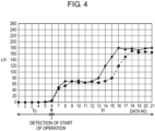
- FIG. 2 is a graph illustrating an example of a measurement timing of flow rate measurer 11 and measured flow rate data in a case where a gas appliance is a gas fan heater.
- FIG. 2 illustrates a relationship between a timing of outputting an operation start signal from operation start detector 17 and flow rate data stored in storage 12.
- a black circle indicates flow rate data measured by flow rate measurer 11 every 0.5 seconds.
- a point in time (Data No. 6) at which the operation start signal is output is used as a starting point, and 5 pieces of flow rate data (Data Nos. 1 to 5) that have been measured during predetermined period Tp before the starting point and 16 pieces of flow rate data (Data Nos. 6 to 21) that have been measured during predetermined period Tf after the starting point are stored and held in storage 12.
- meter communication unit 13 receives, from center device 20, a request signal for flow rate data, from among pieces of flow rate data that have been stored in storage 12, pieces of flow rate data (Data Nos. 1 to 21) that correspond to predetermined periods Tp and Tf are transmitted to the center device.
- the flow rate data is transmitted in a state where a serial number of gas meter 10, date and time of measurement, and the like are included as additional data.
- analyzer 23 discriminates an appliance that has started to operate based on a pattern of a change in flow rate data at the time of the start of operation that has been received from gas meter 10. For example, as a typical flow rate pattern at a time when a gas fan heater starts to operate, as illustrated in FIG. 2 , slow ignition appears by which a flow rate temporarily becomes almost constant in the middle of arrival at a maximum flow rate. Therefore, by detecting this slow ignition, a gas appliance that has started to operate is determined to be a gas fan heater. In the discrimination of an appliance, the consideration of temperature data and pressure data enables an accuracy of discrimination to be improved. Then, a discrimination result is stored together with the serial number of gas meter 10 and date and time of the start of operation in data accumulation unit 22.
- one gas meter 10 is installed in each residence, and therefore the serial number of gas meter 10 can be used to identify a user. Accordingly, by storing an analysis result in combination with the serial number of gas meter 10, a gas appliance installed in a residence of an individual user can be grasped. In addition, by registering a user's email address or the like in association with the serial number of gas meter 10, a message can be distributed to terminal 30 of the user from message distributor 24.
- analyzer 23 The content of analysis performed by analyzer 23 and the content of a message generated by message distributor 24 are described below with reference to FIG. 3 .
- Item A indicates that it is detected that a specified gas appliance such as a heater has started to be used in a season and a message that corresponds to detection is distributed.
- a specified gas appliance such as a heater has started to be used in a season
- a message that corresponds to detection is distributed.
- the message "FH started to be used yesterday. Normal charge will be discounted by ⁇ %.” is distributed in order to promote the use of gas.
- Item B indicates that it is detected that a gas fan heater has not been used although winter has come and a message that corresponds to detection is distributed. In order to promote the use of gas, the message "FH has not been used this winter. In this season, FH can achieve more economical heating than air conditioner.” is distributed.
- Item C indicates that the failure or deterioration of a gas appliance is detected and a message that corresponds to detection is distributed. For example, a change in a flow rate (a dotted line) after the current start of operation of the same gas fan heater is compared with a change in a flow rate of last year (a solid line) that has been stored in data accumulation unit 22. By doing this, it is determined from a difference such as an extended time period of slow ignition or a reduction in a maximum flow rate that there is a possibility of the occurrence of some kind of abnormality in the gas fan heater, and the message "Is it more difficult to ignite FH than last year. Inspection/replacement of gas appliance is recommended.” is distributed in order to attract attention of a user.
- Item D indicates that a time period or years of use of a gas appliance are detected and a message that corresponds to detection is distributed.
- An accumulated time period of use is calculated by integrating both a time period of operation of the same gas fan heater and a time period of use in the past that has been stored in data accumulation unit 22.
- the message "Operation time period of FH exceeds ⁇ hours. Replacement of filter or inspection/replacement of appliance is recommended.” is distributed in order to attract attention of a user.
- Item E indicates that the failure of a gas appliance is predicted and a message that corresponds to detection is distributed.
- a deterioration state and a change over time of the gas appliance are determined, and a future risk of a failure is reported in advance.
- the message "Abnormal flow rate pattern has been detected. There is possibility of failure in several years.” is distributed in order to attract attention of a user.
- Item F indicates the promotion of replacement.
- a model of a gas appliance is specified in the discrimination of an appliance, and in a case where the gas appliance is an old model, a latest model is recommended. For example, the message "Latest gas fan heater saves energy. Replacement is economical.” is distributed.
- a gas appliance monitoring system in first disclosure includes a gas meter including a flow rate measurer, a storage, and a meter communication unit.
- the flow rate measurer measures a flow rate of gas in time series.
- the storage stores, as flow rate data, the flow rate measured by the flow rate measurer.
- the meter communication unit performs communication with a center device.
- This gas appliance monitoring system also includes the center device including a center communication unit, a data accumulation storage, and an analyzer.
- the center communication unit performs communication with the gas meter to receive the flow rate data.
- the data accumulation storage accumulates the received flow rate data.
- the analyzer analyzes the flow rate data.
- the gas meter detects the start of operation of a gas appliance, stores flow rate data during predetermined periods before and after the start of operation, and transmits the flow rate data in accordance with a request from the center device.
- the center device monitors a state of use of the gas appliance based on the flow rate data accumulated in the data accumulation storage.
- an amount of data to be communicated can be reduced by limiting flow rate data to be transmitted from the gas meter to the center device to flow rate data at a time when the gas appliance starts to be used, and the gas appliance can be monitored based on a result of analysis performed by the center device.
- a gas appliance monitoring system has a configuration in which the center device includes a message distributor, and the center device analyzes the flow rate data that has been accumulated in the data accumulation storage, by using the analyzer, and generates a predetermined message based on analysis performed by the analyzer and distributes the predetermined message to a specified distribution destination, by using the message distributor.
- a gas appliance monitoring system in third disclosure may have a configuration in which, in particular, in the second disclosure, the analyzer determines the state of the use of the gas appliance, and the message distributor generates and distributes a message relating to the specified gas appliance.
- a gas appliance monitoring system enables various types of analysis to be performed by using flow rate data measured by a gas meter. Therefore, the gas appliance monitoring system according to the present invention is not only applicable to a gas meter for household use, but is also applicable to a gas meter for business use.
Landscapes
- Physics & Mathematics (AREA)
- General Physics & Mathematics (AREA)
- Engineering & Computer Science (AREA)
- Fluid Mechanics (AREA)
- Chemical & Material Sciences (AREA)
- Combustion & Propulsion (AREA)
- Mechanical Engineering (AREA)
- General Engineering & Computer Science (AREA)
- Thermal Sciences (AREA)
- Measuring Volume Flow (AREA)
- Details Of Flowmeters (AREA)
- Feeding And Controlling Fuel (AREA)
Claims (3)
- Système de surveillance d'appareil à gaz (1) comprenant :un dispositif central (20), un compteur à gaz (10) incluant un mesureur de débit (11), un stockage (12), et une unité de communication de compteur (13), le mesureur de débit (11) mesurant un débit de gaz en série chronologique, le stockage (12) stockant, en tant que données de débit, le débit mesuré par le mesureur de débit (11), l'unité de communication de compteur (13) réalisant une communication avec le dispositif central (20), etle dispositif central (20) incluant une unité de communication centrale (21), un stockage d'accumulation de données (22), et un analyseur (23), l'unité de communication centrale (21) étant configurée pour réaliser une communication avec le compteur à gaz (10) pour recevoir les données de débit, le stockage d'accumulation de données (22) étant configuré pour accumuler les données de débit qui ont été reçues, et l'analyseur (23) étant configuré pour analyser les données de débit,dans lequelle dispositif central (20) inclut un distributeur de message (24), etle dispositif central (20) est configuré pour surveiller un état d'utilisation de l'appareil à gaz (14, 15, 16) sur la base des données de débit qui ont été accumulées dans le stockage d'accumulation de données (22),dans lequel le compteur à gaz (10) est configuré pour détecter un commencement de fonctionnement d'un appareil à gaz (14, 15, 16), caractérisé en ce quele compteur à gaz est configuré pour stocker les données de débit durant des périodes prédéterminées (Tp, Tf) avant et après le commencement de fonctionnement, etle compteur à gaz (10) est configuré pour transmettre, parmi des éléments des données de débit qui ont été stockées dans le stockage (12), seulement des éléments des données de débit qui correspondent aux périodes prédéterminées (Tp, Tf) avant et après le commencement de fonctionnement, sur la base d'une demande provenant du dispositif central (20), afin de réduire une quantité de données destinées à être communiquées, etle dispositif central (20) est configuré pour analyser les données de débit qui correspondent aux périodes prédéterminées (Tp, Tf) avant et après le commencement de fonctionnement qui ont été accumulées dans le stockage d'accumulation de données (22), en utilisant l'analyseur (23), et pour générer un message prédéterminé sur la base d'une analyse réalisée par l'analyseur (23) des données de débit qui correspondent aux périodes prédéterminées (Tp, Tf) avant et après le commencement de fonctionnement et distribuer le message prédéterminé à un terminal (30) d'un utilisateur de l'appareil à gaz (14, 15, 16), en utilisant le distributeur de message (24).
- Système de surveillance d'appareil à gaz (1) selon la revendication 1,
dans lequell'analyseur (23) est configuré pour déterminer l'état de l'utilisation de l'appareil à gaz (14, 15, 16), etle distributeur de message (24) est configuré pour générer et distribuer le message prédéterminé concernant l'appareil à gaz (14, 15, 16) qui a été spécifié. - Système de surveillance d'appareil à gaz (1) selon la revendication 1,
dans lequelle contenu du message prédéterminé indique qu'il a été détecté que l'appareil à gaz (14, 15, 16) a commencé d'être utilisé, ouqu'il a été détecté que l'appareil à gaz (14, 15, 16) n' pas été utilisé, ouqu'une défaillance ou détérioration de l'appareil à gaz (14, 15, 16) a été détectée, ouqu'une durée de vie utile prédéterminée de l'appareil à gaz (14, 15, 16) a été détectée, ouqu'une défaillance de l'appareil à gaz (14, 15, 16) est prédite, ouque le remplacement de l'appareil à gaz (14, 15, 16) est encouragé.
Applications Claiming Priority (2)
| Application Number | Priority Date | Filing Date | Title |
|---|---|---|---|
| JP2017121019A JP6890228B2 (ja) | 2017-06-21 | 2017-06-21 | ガス器具監視システム |
| PCT/JP2018/022307 WO2018235670A1 (fr) | 2017-06-21 | 2018-06-12 | Système de surveillance d'appareil à gaz |
Publications (3)
| Publication Number | Publication Date |
|---|---|
| EP3644023A1 EP3644023A1 (fr) | 2020-04-29 |
| EP3644023A4 EP3644023A4 (fr) | 2020-06-17 |
| EP3644023B1 true EP3644023B1 (fr) | 2024-07-31 |
Family
ID=64737677
Family Applications (1)
| Application Number | Title | Priority Date | Filing Date |
|---|---|---|---|
| EP18819971.5A Active EP3644023B1 (fr) | 2017-06-21 | 2018-06-12 | Système de surveillance d'appareil fonctionnant au gaz |
Country Status (8)
| Country | Link |
|---|---|
| US (1) | US11112289B2 (fr) |
| EP (1) | EP3644023B1 (fr) |
| JP (1) | JP6890228B2 (fr) |
| CN (2) | CN118640985A (fr) |
| ES (1) | ES2987480T3 (fr) |
| PL (1) | PL3644023T3 (fr) |
| PT (1) | PT3644023T (fr) |
| WO (1) | WO2018235670A1 (fr) |
Families Citing this family (1)
| Publication number | Priority date | Publication date | Assignee | Title |
|---|---|---|---|---|
| JP2023013379A (ja) * | 2021-07-16 | 2023-01-26 | パナソニックIpマネジメント株式会社 | ガスメータ |
Citations (2)
| Publication number | Priority date | Publication date | Assignee | Title |
|---|---|---|---|---|
| EP2175247A1 (fr) * | 2007-08-06 | 2010-04-14 | Panasonic Corporation | Dispositif de mesure de débit, système de communication, procédé de mesure de débit, programme de mesure de débit, système d'alimentation de fluide, et dispositif de contrôle d'outil de gaz |
| US20160117070A1 (en) * | 2014-10-28 | 2016-04-28 | Hydro-Care International Inc. | Graphical User Interfaces for Resource Consumption Analytics |
Family Cites Families (18)
| Publication number | Priority date | Publication date | Assignee | Title |
|---|---|---|---|---|
| US7236908B2 (en) * | 2005-11-29 | 2007-06-26 | Elster Electricity, Llc | Fuzzy time-of-use metering and consumption monitoring using load profile data from relative time transmit-only devices |
| JP4556923B2 (ja) * | 2006-07-10 | 2010-10-06 | パナソニック株式会社 | ガス器具監視装置 |
| JP2008059039A (ja) | 2006-08-29 | 2008-03-13 | Ricoh Elemex Corp | 支援データ提供システム及びプログラム |
| JP5076506B2 (ja) * | 2007-01-15 | 2012-11-21 | パナソニック株式会社 | 流量計測装置およびそのプログラム |
| JP5168949B2 (ja) * | 2007-03-01 | 2013-03-27 | パナソニック株式会社 | ガス器具監視装置 |
| EP2131162A4 (fr) * | 2007-03-23 | 2014-07-30 | Panasonic Corp | Appareil de surveillance d'appareil au gaz |
| KR20100075819A (ko) | 2007-08-06 | 2010-07-05 | 파나소닉 주식회사 | 유량 계측 장치, 유량 계측 시스템, 및 유량 계측 방법 |
| JP2009052895A (ja) * | 2007-08-23 | 2009-03-12 | Panasonic Corp | ガス遮断装置 |
| EP2251602A4 (fr) * | 2008-02-26 | 2011-06-29 | Panasonic Corp | Dispositif de coupure de gaz et compteur de système compatible avec une alarme |
| KR20100120198A (ko) * | 2008-03-06 | 2010-11-12 | 파나소닉 주식회사 | 기구 관리 시스템 및 가스 공급 시스템 |
| US8118238B2 (en) * | 2008-12-10 | 2012-02-21 | Honeywell International Inc. | User interface for building controller |
| JP5436175B2 (ja) * | 2009-12-03 | 2014-03-05 | 矢崎エナジーシステム株式会社 | ガス使用状況判断システム及びガス使用状況判断方法 |
| CN102829231B (zh) * | 2011-06-17 | 2016-08-03 | 博西华电器(江苏)有限公司 | 燃气阀装置及燃气灶 |
| CN202795696U (zh) * | 2012-06-22 | 2013-03-13 | 郭贤生 | 一种java平台下的智能家居安防系统 |
| CN103914919B (zh) * | 2013-12-31 | 2017-01-18 | 北京市燃气集团有限责任公司 | 一种燃气计量装置、燃气计量信息上报方法 |
| CN104281081A (zh) * | 2014-10-23 | 2015-01-14 | 天津光电华典科技有限公司 | 一种智能家居无线接入装置、系统及方法 |
| CN105805954A (zh) * | 2016-03-24 | 2016-07-27 | 苏州路之遥科技股份有限公司 | 一种基于物联网技术的燃气热水系统 |
| CN105955147A (zh) | 2016-06-30 | 2016-09-21 | 南京嘉瑞斯电力科技有限公司 | 一种基于流量传感器的家居燃气监控系统 |
-
2017
- 2017-06-21 JP JP2017121019A patent/JP6890228B2/ja active Active
-
2018
- 2018-06-12 US US16/615,800 patent/US11112289B2/en not_active Expired - Fee Related
- 2018-06-12 EP EP18819971.5A patent/EP3644023B1/fr active Active
- 2018-06-12 CN CN202410855482.2A patent/CN118640985A/zh active Pending
- 2018-06-12 PT PT188199715T patent/PT3644023T/pt unknown
- 2018-06-12 ES ES18819971T patent/ES2987480T3/es active Active
- 2018-06-12 WO PCT/JP2018/022307 patent/WO2018235670A1/fr not_active Ceased
- 2018-06-12 CN CN201880041239.XA patent/CN110799811A/zh active Pending
- 2018-06-12 PL PL18819971.5T patent/PL3644023T3/pl unknown
Patent Citations (2)
| Publication number | Priority date | Publication date | Assignee | Title |
|---|---|---|---|---|
| EP2175247A1 (fr) * | 2007-08-06 | 2010-04-14 | Panasonic Corporation | Dispositif de mesure de débit, système de communication, procédé de mesure de débit, programme de mesure de débit, système d'alimentation de fluide, et dispositif de contrôle d'outil de gaz |
| US20160117070A1 (en) * | 2014-10-28 | 2016-04-28 | Hydro-Care International Inc. | Graphical User Interfaces for Resource Consumption Analytics |
Also Published As
| Publication number | Publication date |
|---|---|
| JP2019007637A (ja) | 2019-01-17 |
| WO2018235670A1 (fr) | 2018-12-27 |
| CN110799811A (zh) | 2020-02-14 |
| PL3644023T3 (pl) | 2024-12-02 |
| CN118640985A (zh) | 2024-09-13 |
| EP3644023A1 (fr) | 2020-04-29 |
| PT3644023T (pt) | 2024-09-26 |
| ES2987480T3 (es) | 2024-11-15 |
| US20200182674A1 (en) | 2020-06-11 |
| US11112289B2 (en) | 2021-09-07 |
| JP6890228B2 (ja) | 2021-06-18 |
| EP3644023A4 (fr) | 2020-06-17 |
Similar Documents
| Publication | Publication Date | Title |
|---|---|---|
| AU2011261327B2 (en) | Method and system for non-intrusive load monitoring and processing | |
| US9267971B2 (en) | Energy consumption monitoring system, method, and computer program | |
| US20170350946A1 (en) | Storage battery state monitoring system, storage battery state monitoring method, and storage battery state monitoring program | |
| EP3644024B1 (fr) | Compteur de gaz | |
| EP3647744B1 (fr) | Système de gestion de compteurs de gaz | |
| JPWO2007122902A1 (ja) | 基板処理装置の管理方法 | |
| EP3644023B1 (fr) | Système de surveillance d'appareil fonctionnant au gaz | |
| US11959825B2 (en) | Method and a condition monitoring device for monitoring a rotating equipment | |
| CN108076086B (zh) | 一种远程监控方法及设备 | |
| JP6147205B2 (ja) | メータデータ確認装置及びメータデータ確認方法 | |
| JP6738896B2 (ja) | 施設内のリソースフローを監視することによるエラー状態の検出 | |
| JP2012215391A (ja) | 点検スケジュール作成装置 | |
| JP5105759B2 (ja) | 蓄電池管理装置 | |
| JP7127461B2 (ja) | データ管理システム | |
| CN215728765U (zh) | 一种基于电能表的异常监测系统 | |
| JP2025135000A (ja) | ガスメータ | |
| JP2012026778A (ja) | 一次電池の残量検出方法及び残量検出装置 | |
| EP3451274B1 (fr) | Procédé de détection séparée de la consommation d'électricité et d'eau pour des dispositifs respectifs | |
| CN121464364A (zh) | 电池分析系统、电池分析方法以及电池分析程序 | |
| CN121444250A (zh) | 电池分析系统、电池分析方法以及电池分析程序 | |
| JP2003029820A (ja) | 発電所監視システム |
Legal Events
| Date | Code | Title | Description |
|---|---|---|---|
| STAA | Information on the status of an ep patent application or granted ep patent |
Free format text: STATUS: THE INTERNATIONAL PUBLICATION HAS BEEN MADE |
|
| PUAI | Public reference made under article 153(3) epc to a published international application that has entered the european phase |
Free format text: ORIGINAL CODE: 0009012 |
|
| STAA | Information on the status of an ep patent application or granted ep patent |
Free format text: STATUS: REQUEST FOR EXAMINATION WAS MADE |
|
| 17P | Request for examination filed |
Effective date: 20191121 |
|
| AK | Designated contracting states |
Kind code of ref document: A1 Designated state(s): AL AT BE BG CH CY CZ DE DK EE ES FI FR GB GR HR HU IE IS IT LI LT LU LV MC MK MT NL NO PL PT RO RS SE SI SK SM TR |
|
| AX | Request for extension of the european patent |
Extension state: BA ME |
|
| A4 | Supplementary search report drawn up and despatched |
Effective date: 20200514 |
|
| RIC1 | Information provided on ipc code assigned before grant |
Ipc: G01F 3/22 20060101AFI20200508BHEP Ipc: G01F 1/00 20060101ALI20200508BHEP Ipc: F23K 5/00 20060101ALI20200508BHEP Ipc: G01F 15/06 20060101ALI20200508BHEP |
|
| DAV | Request for validation of the european patent (deleted) | ||
| DAX | Request for extension of the european patent (deleted) | ||
| STAA | Information on the status of an ep patent application or granted ep patent |
Free format text: STATUS: EXAMINATION IS IN PROGRESS |
|
| 17Q | First examination report despatched |
Effective date: 20210608 |
|
| REG | Reference to a national code |
Ref country code: DE Ref legal event code: R079 Ref country code: DE Ref legal event code: R079 Ref document number: 602018072514 Country of ref document: DE Free format text: PREVIOUS MAIN CLASS: G01F0003220000 Ipc: G01F0015075000 |
|
| GRAP | Despatch of communication of intention to grant a patent |
Free format text: ORIGINAL CODE: EPIDOSNIGR1 |
|
| STAA | Information on the status of an ep patent application or granted ep patent |
Free format text: STATUS: GRANT OF PATENT IS INTENDED |
|
| RIC1 | Information provided on ipc code assigned before grant |
Ipc: F23K 5/00 20060101ALI20240130BHEP Ipc: G01F 15/06 20060101ALI20240130BHEP Ipc: G01F 3/22 20060101ALI20240130BHEP Ipc: G01F 1/00 20060101ALI20240130BHEP Ipc: G01F 15/063 20220101ALI20240130BHEP Ipc: G01D 4/00 20060101ALI20240130BHEP Ipc: G01F 15/07 20060101ALI20240130BHEP Ipc: G01F 15/075 20060101AFI20240130BHEP |
|
| INTG | Intention to grant announced |
Effective date: 20240215 |
|
| GRAS | Grant fee paid |
Free format text: ORIGINAL CODE: EPIDOSNIGR3 |
|
| GRAA | (expected) grant |
Free format text: ORIGINAL CODE: 0009210 |
|
| STAA | Information on the status of an ep patent application or granted ep patent |
Free format text: STATUS: THE PATENT HAS BEEN GRANTED |
|
| AK | Designated contracting states |
Kind code of ref document: B1 Designated state(s): AL AT BE BG CH CY CZ DE DK EE ES FI FR GB GR HR HU IE IS IT LI LT LU LV MC MK MT NL NO PL PT RO RS SE SI SK SM TR |
|
| REG | Reference to a national code |
Ref country code: CH Ref legal event code: EP Ref country code: GB Ref legal event code: FG4D |
|
| REG | Reference to a national code |
Ref country code: DE Ref legal event code: R096 Ref document number: 602018072514 Country of ref document: DE |
|
| REG | Reference to a national code |
Ref country code: IE Ref legal event code: FG4D |
|
| REG | Reference to a national code |
Ref country code: PT Ref legal event code: SC4A Ref document number: 3644023 Country of ref document: PT Date of ref document: 20240926 Kind code of ref document: T Free format text: AVAILABILITY OF NATIONAL TRANSLATION Effective date: 20240920 |
|
| REG | Reference to a national code |
Ref country code: ES Ref legal event code: FG2A Ref document number: 2987480 Country of ref document: ES Kind code of ref document: T3 Effective date: 20241115 |
|
| REG | Reference to a national code |
Ref country code: LT Ref legal event code: MG9D |
|
| REG | Reference to a national code |
Ref country code: NL Ref legal event code: MP Effective date: 20240731 |
|
| REG | Reference to a national code |
Ref country code: AT Ref legal event code: MK05 Ref document number: 1708862 Country of ref document: AT Kind code of ref document: T Effective date: 20240731 |
|
| PG25 | Lapsed in a contracting state [announced via postgrant information from national office to epo] |
Ref country code: NO Free format text: LAPSE BECAUSE OF FAILURE TO SUBMIT A TRANSLATION OF THE DESCRIPTION OR TO PAY THE FEE WITHIN THE PRESCRIBED TIME-LIMIT Effective date: 20241031 |
|
| PG25 | Lapsed in a contracting state [announced via postgrant information from national office to epo] |
Ref country code: FI Free format text: LAPSE BECAUSE OF FAILURE TO SUBMIT A TRANSLATION OF THE DESCRIPTION OR TO PAY THE FEE WITHIN THE PRESCRIBED TIME-LIMIT Effective date: 20240731 Ref country code: NL Free format text: LAPSE BECAUSE OF FAILURE TO SUBMIT A TRANSLATION OF THE DESCRIPTION OR TO PAY THE FEE WITHIN THE PRESCRIBED TIME-LIMIT Effective date: 20240731 Ref country code: GR Free format text: LAPSE BECAUSE OF FAILURE TO SUBMIT A TRANSLATION OF THE DESCRIPTION OR TO PAY THE FEE WITHIN THE PRESCRIBED TIME-LIMIT Effective date: 20241101 |
|
| PG25 | Lapsed in a contracting state [announced via postgrant information from national office to epo] |
Ref country code: BG Free format text: LAPSE BECAUSE OF FAILURE TO SUBMIT A TRANSLATION OF THE DESCRIPTION OR TO PAY THE FEE WITHIN THE PRESCRIBED TIME-LIMIT Effective date: 20240731 |
|
| PG25 | Lapsed in a contracting state [announced via postgrant information from national office to epo] |
Ref country code: LV Free format text: LAPSE BECAUSE OF FAILURE TO SUBMIT A TRANSLATION OF THE DESCRIPTION OR TO PAY THE FEE WITHIN THE PRESCRIBED TIME-LIMIT Effective date: 20240731 |
|
| PG25 | Lapsed in a contracting state [announced via postgrant information from national office to epo] |
Ref country code: IS Free format text: LAPSE BECAUSE OF FAILURE TO SUBMIT A TRANSLATION OF THE DESCRIPTION OR TO PAY THE FEE WITHIN THE PRESCRIBED TIME-LIMIT Effective date: 20241130 Ref country code: AT Free format text: LAPSE BECAUSE OF FAILURE TO SUBMIT A TRANSLATION OF THE DESCRIPTION OR TO PAY THE FEE WITHIN THE PRESCRIBED TIME-LIMIT Effective date: 20240731 |
|
| PG25 | Lapsed in a contracting state [announced via postgrant information from national office to epo] |
Ref country code: HR Free format text: LAPSE BECAUSE OF FAILURE TO SUBMIT A TRANSLATION OF THE DESCRIPTION OR TO PAY THE FEE WITHIN THE PRESCRIBED TIME-LIMIT Effective date: 20240731 |
|
| PG25 | Lapsed in a contracting state [announced via postgrant information from national office to epo] |
Ref country code: RS Free format text: LAPSE BECAUSE OF FAILURE TO SUBMIT A TRANSLATION OF THE DESCRIPTION OR TO PAY THE FEE WITHIN THE PRESCRIBED TIME-LIMIT Effective date: 20241031 |
|
| PG25 | Lapsed in a contracting state [announced via postgrant information from national office to epo] |
Ref country code: RS Free format text: LAPSE BECAUSE OF FAILURE TO SUBMIT A TRANSLATION OF THE DESCRIPTION OR TO PAY THE FEE WITHIN THE PRESCRIBED TIME-LIMIT Effective date: 20241031 Ref country code: NO Free format text: LAPSE BECAUSE OF FAILURE TO SUBMIT A TRANSLATION OF THE DESCRIPTION OR TO PAY THE FEE WITHIN THE PRESCRIBED TIME-LIMIT Effective date: 20241031 Ref country code: NL Free format text: LAPSE BECAUSE OF FAILURE TO SUBMIT A TRANSLATION OF THE DESCRIPTION OR TO PAY THE FEE WITHIN THE PRESCRIBED TIME-LIMIT Effective date: 20240731 Ref country code: LV Free format text: LAPSE BECAUSE OF FAILURE TO SUBMIT A TRANSLATION OF THE DESCRIPTION OR TO PAY THE FEE WITHIN THE PRESCRIBED TIME-LIMIT Effective date: 20240731 Ref country code: IS Free format text: LAPSE BECAUSE OF FAILURE TO SUBMIT A TRANSLATION OF THE DESCRIPTION OR TO PAY THE FEE WITHIN THE PRESCRIBED TIME-LIMIT Effective date: 20241130 Ref country code: HR Free format text: LAPSE BECAUSE OF FAILURE TO SUBMIT A TRANSLATION OF THE DESCRIPTION OR TO PAY THE FEE WITHIN THE PRESCRIBED TIME-LIMIT Effective date: 20240731 Ref country code: GR Free format text: LAPSE BECAUSE OF FAILURE TO SUBMIT A TRANSLATION OF THE DESCRIPTION OR TO PAY THE FEE WITHIN THE PRESCRIBED TIME-LIMIT Effective date: 20241101 Ref country code: FI Free format text: LAPSE BECAUSE OF FAILURE TO SUBMIT A TRANSLATION OF THE DESCRIPTION OR TO PAY THE FEE WITHIN THE PRESCRIBED TIME-LIMIT Effective date: 20240731 Ref country code: BG Free format text: LAPSE BECAUSE OF FAILURE TO SUBMIT A TRANSLATION OF THE DESCRIPTION OR TO PAY THE FEE WITHIN THE PRESCRIBED TIME-LIMIT Effective date: 20240731 Ref country code: AT Free format text: LAPSE BECAUSE OF FAILURE TO SUBMIT A TRANSLATION OF THE DESCRIPTION OR TO PAY THE FEE WITHIN THE PRESCRIBED TIME-LIMIT Effective date: 20240731 |
|
| PG25 | Lapsed in a contracting state [announced via postgrant information from national office to epo] |
Ref country code: SM Free format text: LAPSE BECAUSE OF FAILURE TO SUBMIT A TRANSLATION OF THE DESCRIPTION OR TO PAY THE FEE WITHIN THE PRESCRIBED TIME-LIMIT Effective date: 20240731 Ref country code: DK Free format text: LAPSE BECAUSE OF FAILURE TO SUBMIT A TRANSLATION OF THE DESCRIPTION OR TO PAY THE FEE WITHIN THE PRESCRIBED TIME-LIMIT Effective date: 20240731 Ref country code: RO Free format text: LAPSE BECAUSE OF FAILURE TO SUBMIT A TRANSLATION OF THE DESCRIPTION OR TO PAY THE FEE WITHIN THE PRESCRIBED TIME-LIMIT Effective date: 20240731 |
|
| PG25 | Lapsed in a contracting state [announced via postgrant information from national office to epo] |
Ref country code: EE Free format text: LAPSE BECAUSE OF FAILURE TO SUBMIT A TRANSLATION OF THE DESCRIPTION OR TO PAY THE FEE WITHIN THE PRESCRIBED TIME-LIMIT Effective date: 20240731 |
|
| PG25 | Lapsed in a contracting state [announced via postgrant information from national office to epo] |
Ref country code: CZ Free format text: LAPSE BECAUSE OF FAILURE TO SUBMIT A TRANSLATION OF THE DESCRIPTION OR TO PAY THE FEE WITHIN THE PRESCRIBED TIME-LIMIT Effective date: 20240731 |
|
| PG25 | Lapsed in a contracting state [announced via postgrant information from national office to epo] |
Ref country code: SK Free format text: LAPSE BECAUSE OF FAILURE TO SUBMIT A TRANSLATION OF THE DESCRIPTION OR TO PAY THE FEE WITHIN THE PRESCRIBED TIME-LIMIT Effective date: 20240731 |
|
| REG | Reference to a national code |
Ref country code: DE Ref legal event code: R097 Ref document number: 602018072514 Country of ref document: DE |
|
| PLBE | No opposition filed within time limit |
Free format text: ORIGINAL CODE: 0009261 |
|
| STAA | Information on the status of an ep patent application or granted ep patent |
Free format text: STATUS: NO OPPOSITION FILED WITHIN TIME LIMIT |
|
| 26N | No opposition filed |
Effective date: 20250501 |
|
| PGFP | Annual fee paid to national office [announced via postgrant information from national office to epo] |
Ref country code: PL Payment date: 20250602 Year of fee payment: 8 |
|
| PGFP | Annual fee paid to national office [announced via postgrant information from national office to epo] |
Ref country code: PT Payment date: 20250529 Year of fee payment: 8 |
|
| PG25 | Lapsed in a contracting state [announced via postgrant information from national office to epo] |
Ref country code: SE Free format text: LAPSE BECAUSE OF FAILURE TO SUBMIT A TRANSLATION OF THE DESCRIPTION OR TO PAY THE FEE WITHIN THE PRESCRIBED TIME-LIMIT Effective date: 20240731 |
|
| PGFP | Annual fee paid to national office [announced via postgrant information from national office to epo] |
Ref country code: ES Payment date: 20250728 Year of fee payment: 8 |
|
| PGFP | Annual fee paid to national office [announced via postgrant information from national office to epo] |
Ref country code: IT Payment date: 20250624 Year of fee payment: 8 |
|
| REG | Reference to a national code |
Ref country code: DE Ref legal event code: R119 Ref document number: 602018072514 Country of ref document: DE |
|
| REG | Reference to a national code |
Ref country code: CH Ref legal event code: H13 Free format text: ST27 STATUS EVENT CODE: U-0-0-H10-H13 (AS PROVIDED BY THE NATIONAL OFFICE) Effective date: 20260127 |
|
| PG25 | Lapsed in a contracting state [announced via postgrant information from national office to epo] |
Ref country code: MC Free format text: LAPSE BECAUSE OF FAILURE TO SUBMIT A TRANSLATION OF THE DESCRIPTION OR TO PAY THE FEE WITHIN THE PRESCRIBED TIME-LIMIT Effective date: 20240731 |
|
| PG25 | Lapsed in a contracting state [announced via postgrant information from national office to epo] |
Ref country code: LU Free format text: LAPSE BECAUSE OF NON-PAYMENT OF DUE FEES Effective date: 20250612 |
|
| GBPC | Gb: european patent ceased through non-payment of renewal fee |
Effective date: 20250612 |
|
| REG | Reference to a national code |
Ref country code: BE Ref legal event code: MM Effective date: 20250630 |
|
| PG25 | Lapsed in a contracting state [announced via postgrant information from national office to epo] |
Ref country code: GB Free format text: LAPSE BECAUSE OF NON-PAYMENT OF DUE FEES Effective date: 20250612 |
|
| PG25 | Lapsed in a contracting state [announced via postgrant information from national office to epo] |
Ref country code: DE Free format text: LAPSE BECAUSE OF NON-PAYMENT OF DUE FEES Effective date: 20260101 Ref country code: IE Free format text: LAPSE BECAUSE OF NON-PAYMENT OF DUE FEES Effective date: 20250612 |
|
| PG25 | Lapsed in a contracting state [announced via postgrant information from national office to epo] |
Ref country code: BE Free format text: LAPSE BECAUSE OF NON-PAYMENT OF DUE FEES Effective date: 20250630 |
|
| PG25 | Lapsed in a contracting state [announced via postgrant information from national office to epo] |
Ref country code: FR Free format text: LAPSE BECAUSE OF NON-PAYMENT OF DUE FEES Effective date: 20250630 |