EP3644094B1 - Caméra temps de vol 3d et procédé de détection de données d'image tridimensionnelles - Google Patents
Caméra temps de vol 3d et procédé de détection de données d'image tridimensionnelles Download PDFInfo
- Publication number
- EP3644094B1 EP3644094B1 EP19200317.6A EP19200317A EP3644094B1 EP 3644094 B1 EP3644094 B1 EP 3644094B1 EP 19200317 A EP19200317 A EP 19200317A EP 3644094 B1 EP3644094 B1 EP 3644094B1
- Authority
- EP
- European Patent Office
- Prior art keywords
- time
- flight camera
- distance
- charge
- receiving
- Prior art date
- Legal status (The legal status is an assumption and is not a legal conclusion. Google has not performed a legal analysis and makes no representation as to the accuracy of the status listed.)
- Active
Links
Images

Classifications
-
- G—PHYSICS
- G01—MEASURING; TESTING
- G01S—RADIO DIRECTION-FINDING; RADIO NAVIGATION; DETERMINING DISTANCE OR VELOCITY BY USE OF RADIO WAVES; LOCATING OR PRESENCE-DETECTING BY USE OF THE REFLECTION OR RERADIATION OF RADIO WAVES; ANALOGOUS ARRANGEMENTS USING OTHER WAVES
- G01S7/00—Details of systems according to groups G01S13/00, G01S15/00, G01S17/00
- G01S7/48—Details of systems according to groups G01S13/00, G01S15/00, G01S17/00 of systems according to group G01S17/00
- G01S7/491—Details of non-pulse systems
- G01S7/4912—Receivers
- G01S7/4913—Circuits for detection, sampling, integration or read-out
- G01S7/4914—Circuits for detection, sampling, integration or read-out of detector arrays, e.g. charge-transfer gates
-
- G—PHYSICS
- G01—MEASURING; TESTING
- G01S—RADIO DIRECTION-FINDING; RADIO NAVIGATION; DETERMINING DISTANCE OR VELOCITY BY USE OF RADIO WAVES; LOCATING OR PRESENCE-DETECTING BY USE OF THE REFLECTION OR RERADIATION OF RADIO WAVES; ANALOGOUS ARRANGEMENTS USING OTHER WAVES
- G01S17/00—Systems using the reflection or reradiation of electromagnetic waves other than radio waves, e.g. lidar systems
- G01S17/02—Systems using the reflection of electromagnetic waves other than radio waves
- G01S17/06—Systems determining position data of a target
- G01S17/08—Systems determining position data of a target for measuring distance only
- G01S17/32—Systems determining position data of a target for measuring distance only using transmission of continuous waves, whether amplitude-, frequency-, or phase-modulated, or unmodulated
- G01S17/36—Systems determining position data of a target for measuring distance only using transmission of continuous waves, whether amplitude-, frequency-, or phase-modulated, or unmodulated with phase comparison between the received signal and the contemporaneously transmitted signal
-
- G—PHYSICS
- G01—MEASURING; TESTING
- G01S—RADIO DIRECTION-FINDING; RADIO NAVIGATION; DETERMINING DISTANCE OR VELOCITY BY USE OF RADIO WAVES; LOCATING OR PRESENCE-DETECTING BY USE OF THE REFLECTION OR RERADIATION OF RADIO WAVES; ANALOGOUS ARRANGEMENTS USING OTHER WAVES
- G01S17/00—Systems using the reflection or reradiation of electromagnetic waves other than radio waves, e.g. lidar systems
- G01S17/02—Systems using the reflection of electromagnetic waves other than radio waves
- G01S17/50—Systems of measurement based on relative movement of target
- G01S17/58—Velocity or trajectory determination systems; Sense-of-movement determination systems
-
- G—PHYSICS
- G01—MEASURING; TESTING
- G01S—RADIO DIRECTION-FINDING; RADIO NAVIGATION; DETERMINING DISTANCE OR VELOCITY BY USE OF RADIO WAVES; LOCATING OR PRESENCE-DETECTING BY USE OF THE REFLECTION OR RERADIATION OF RADIO WAVES; ANALOGOUS ARRANGEMENTS USING OTHER WAVES
- G01S17/00—Systems using the reflection or reradiation of electromagnetic waves other than radio waves, e.g. lidar systems
- G01S17/88—Lidar systems specially adapted for specific applications
- G01S17/89—Lidar systems specially adapted for specific applications for mapping or imaging
- G01S17/894—Three-dimensional [3D] imaging with simultaneous measurement of time-of-flight at a two-dimensional [2D] array of receiver pixels, e.g. time-of-flight cameras or flash lidar
Definitions
- the invention relates to a 3D time-of-flight camera and a method for capturing three-dimensional image data from a capturing area according to the preamble of claims 1 and 14, respectively.
- a 3D camera In contrast to a conventional camera, a 3D camera also records depth information and thus generates three-dimensional image data with distance or distance values for the individual pixels of the 3D image, which is also referred to as a distance image or depth map.
- the additional distance dimension can be used in a variety of applications to gain more information about objects in the scene captured by the camera and thus to solve various tasks.
- objects can be recorded and classified using three-dimensional image information in order to make further automatic processing steps dependent on which objects were preferably recognized, including their position and orientation.
- This can be used to support the control of robots or various types of actuators on a conveyor belt, for example.
- a 3D camera should be used to record the entire surroundings and in particular a planned route as completely and three-dimensionally as possible. This applies to practically all conceivable vehicles, be it those with a driver such as cars, trucks, work machines and forklifts or driverless vehicles such as AGVs (Automated Guided Vehicles) or industrial trucks.
- the image data is used to enable autonomous navigation or to support a driver, among other things to recognize obstacles, avoid collisions or to facilitate the loading and unloading of goods including boxes, pallets, containers or trailers.
- the 3D camera detects people in the vicinity of a hazard, for example a machine or especially a robot. If an impermissible intervention in a protected volume is detected or if a safety distance to the machine is not reached, a safety-oriented reaction takes place in order to avoid an accident.
- time-of-flight measurements such as time-of-flight measurements or stereoscopy.
- time of flight measurement TOF, Time of Flight or Lidar, Light Detection and Ranging
- solid state lidar is also used for 3D acquisition without such moving parts.
- a scene is illuminated with amplitude-modulated light.
- the camera measures the transit time for each of its image points based on the phase shift between the light emitted and the light received again.
- FIG. 3 shows a conventional modulation scheme.
- S shows the transmitted light that is periodically modulated with a frequency f s .
- the returning received light underneath is labeled E and has a phase offset to the transmitted light S, depending on the distance of the object from which the transmitted light was reflected.
- E The returning received light underneath
- E has a phase offset to the transmitted light S, depending on the distance of the object from which the transmitted light was reflected.
- periods of time which are assigned to the charge stores of the respective pixel of the camera, in which the photoelectrons generated within the respective time period are stored.
- the time segments do not have to be selected to be flush with the transmitted light, as shown, but a possible time offset should be taken into account, since otherwise there will be a measurement error of the phase and thus the distance.
- Figure 4a there are two different charge stores A and B at each pixel, between which the transmitted light is switched back and forth with the modulation frequency f s becomes. It is integrated over a large number of modulation periods, ie the accumulating charge carriers are added up, and only then is the total charge read out from the pixels, whereby Figure 4a shows two such modulation periods.
- the phase sought results from B / (A + B).
- a disadvantage of this simple measurement is the sensitivity to extraneous or background light.
- the EP 3 159 711 A1 discloses a system that uses this method to measure distances to an object.
- the area is not illuminated, but a large number of individual lasers illuminate individual receiving pixels in order to achieve a greater range.
- Background light is measured either with the help of surrounding pixels or by a further exposure cycle without modulated transmitted light and then subtracted in the evaluation.
- this digital background compensation is already replaced in an analogue way by partial discharge before digitization. For this purpose, the charges of the pixels accumulated during the time-of-flight measurement in a first exposure cycle are partially discharged again in a second exposure cycle without modulated transmitted light, depending on the background light present.
- the pixels have only one charge storage device that is switched on and off with the modulation frequency.
- the two measurements according to Figure 4a with charge stores A and B are carried out one after the other. On average over time, however, half of the useful light falls on an inactive pixel and is lost, with a correspondingly deteriorated signal-to-noise ratio and thus a reduced range.
- both measurements must be carried out one after the other. This not only takes twice as long, but with a given measurement time only half of the useful light is available for the individual measurement, with the consequence of a deteriorated signal-to-noise ratio and thus a reduced range.
- Another common proposal is to have some pixels on the camera's image sensor only measure distances and other pixels only to measure speeds. This means that a corresponding proportion of the received light is lost for the respective individual measurement, and the image resolution is also reduced. Both measurements can also take place at the same time by operating two systems in parallel, but this doubles costs and space requirements.
- the U.S. 4,818,100 A1 discloses a measurement of time of flight and Doppler shift with two laser sources and three light detectors. Optical elements are used several times, but in principle there are two measuring systems.
- the US 7 576 839 B2 shows another distance and speed measurement system based on a mechanical shutter for modulation.
- the shutter replaces the switching between charge stores in the receiving pixels. Again, only either distance or speed are measured within a measurement.
- the EP 2 477 043 A1 shows a further 3D time-of-flight camera, the pixels of which have at least two detection units. However, no speeds are measured with it.
- WO 2003/054579 A1 a method for generating 3D distance images is described in which the respective measuring interval is broken down into several sub-intervals by a number of memories. Another memory is used to measure the interfering light within a second time interval before the emission of a light pulse in order to compensate for the 3D distance image accordingly.
- Another memory is used to measure the interfering light within a second time interval before the emission of a light pulse in order to compensate for the 3D distance image accordingly.
- only distances are measured, not speeds.
- a lighting unit illuminates the detection area with transmitted light, the amplitude of which is periodically modulated with a frequency f s .
- the transmitted light reflected by objects in the detection area is superimposed with extraneous or background light and falls on an image sensor with a large number of reception pixels, which generate a respective reception signal.
- An evaluation unit which can be implemented at least partially in or near the reception pixels, evaluates these reception signals by a phase shift between the transmitted and received light and thus a distance value and a Doppler shift for each reception pixel of the received light versus the frequency f s and thus a speed value.
- the invention is based on the basic idea of measuring distance and speed simultaneously with the same receiving pixel.
- a depth map and a speed map are created, i.e. two-dimensional images, the pixels of which contain a distance or a speed.
- Simultaneous measurement means that the photoelectrons generated by the received light contribute to both the distance measurement and the speed measurement. It is not measured twice in succession, as is conventional, with a first measurement for the distance and a second measurement for the speed.
- a measurement of distance and speed with the same receiving pixel means that there are not some receiving pixels assigned to distance measurement and other receiving pixels assigned to speed measurement, either on the same image sensor or in two systems operated in parallel, as in other conventional solutions.
- one and the same receiving pixel measures both distance and speed on the basis of the same registered charge carriers.
- the invention has the advantage that a 3-D time-of-flight camera is created which also measures speeds at the same time. Since the measurements take place simultaneously in the same receiving pixel, each detected photon makes a full contribution to both measured quantities. This does not increase the measurement time compared to a conventional sequential or alternating measurement of the two variables, or in other words, the measurement speed doubles. As an alternative to shorter measuring cycles, the acquired measuring speed can be used to improve the signal-to-noise ratio and thus the range.
- the receiving pixels preferably each have four charge stores. This enables the photoelectrons generated from the received light to be assigned to four different values, from which the distance and speed are then calculated.
- the charge stores are designed, for example, as capacitors.
- the charge stores preferably take up the charge carriers generated in the receiving pixel one after the other.
- the receiving pixels are controlled accordingly by the evaluation unit.
- the charge stores preferably each take up the charge carriers generated in the receiving pixel one after the other over a quarter of the period of the frequency f s .
- four sampling points of the modulation of the received light are obtained in each period 1 / f s .
- the evaluation unit is preferably designed to read one of the values a, b, c and d from the four charge stores.
- the information from the charge stores is thus available for further, preferably digital, processing.
- the assigned names a, b, c and d of the charge stores and the values read out from them are of course interchangeable; any representation in the evaluation unit is conceivable.
- This is a very simple evaluation that in principle would also get by with only two alternately active charge stores when switching after half a period 1 / f s . It is not very robust against background light and level. It is possible to determine the background in another measurement and subtract it from A and B.
- the phase can be determined by a factor cc 4th f s convert to a distance.
- the symbol cc denotes the speed of light.
- An equivalent calculation using (1-A) / (B + A) is also possible.
- A: a + b
- B: c + d
- C: b + c
- D : a + d.
- the addition of the alternately active charge stores a, c and b, d effectively corresponds to a measurement at twice the modulation frequency at the receiving end 2f s . It is therefore since the modulation frequencies differ on the transmission side and the reception side, a heterodyne measurement. Physically, it remains the same measurement that is used to determine the distance. With the help of M and / or N, the Doppler shift and thus the speed can also be measured at the same time.
- This formula does not take into account a constant that depends on the pulse duration and background and that is eliminated, for example, by subtracting or calibrating.
- the evaluation unit is preferably designed to read out the values a, b, c and d after integration over a plurality of periods of the frequency f s . As a result, useful light is collected over a longer period of time and a more precise measurement result is achieved.
- the integration is preferably carried out over an integration period which corresponds to an integral multiple of the period 1 / f s .
- the evaluation unit is preferably designed to offset the speeds measured with a plurality of reception pixels with one another. This can be averaging and lead to a speed map with reduced resolution (downsampling), or smoothing filters with filter cores with different weightings of the respective neighbors are used.
- the calculation is therefore preferably carried out on the speed map because the Doppler measurement is significantly less accurate than the distance measurement. It can therefore be advantageous to sacrifice lateral resolution in the X and Y directions in favor of better speed determination.
- the distance measurement is already more precise in its individual pixels, but it is of course also possible to filter the depth map or Undergo adjustments, for example in order to obtain better comparable depth and speed maps.
- the receiving pixels are preferably designed to remove charge carriers by applying a voltage in a specific direction in which a specific charge storage device is arranged. This is a special design of the receiving pixels, which improves the distribution of the charge carriers to the correct charge storage, even at higher modulation frequencies and thus short switching times.
- the receiving pixels preferably have 2n charge stores with n> 2, which in turn take up the charge carriers generated in the receiving pixel, in particular for 1 / 2n each of the period of the frequency f s .
- the invention is therefore generalized for n> 2. More complex reception pixels then arise, for which the evaluation can fall back on finer information about the intensity profile of the reception light.
- the receiving pixels preferably have an additional charge store for determining extraneous light.
- the additional charge storage does not actually measure the distance or speed, but collects all charge carriers in time intervals without useful light in order to measure the background, with which the evaluation is then compensated.
- a fifth charge store is added, in the terminology of the previous paragraph it is a 2n + 1-th charge store.
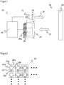
- Figure 1 shows a schematic block diagram of a 3-D time-of-flight camera 10.
- a lighting unit 12 transmits transmitted light 16 modulated by transmission optics 14 into a detection area 18.
- LEDs or lasers in the form of edge emitters or VCSELs can be used as light sources.
- the transmitted light 16 can be generated in the visible wavelength range, in the near-infrared range, for example, at 805 nm or 905 nm, in the mid-infrared range, for example, at 1550 nm, or at other wavelengths.
- the light transmitter 12 can be controlled in such a way that the amplitude of the transmitted light 16 is modulated with a frequency f s , f s typically being in the range from 1 MHz to 1000 MHz.
- the modulation is, for example, sinusoidal or rectangular, in any case a periodic modulation.
- the frequency f s results in a limited uniqueness range of the distance measurement, so that small modulation frequencies f s are required for large ranges of the 3-D time-of-flight camera 10.
- measurements are carried out at two or more modulation frequencies in order to increase the uniqueness range in combination of the measurements.
- the transmitted light 16 hits an object 20 in the detection area 18, part of it is reflected back to the 3-D time-of-flight camera 10 as received light 22 and is guided there to an image sensor 26 by receiving optics 24, for example a single lens or a receiving lens.
- the image sensor 26 has a multiplicity of light detectors or receiving pixels 26a arranged, for example, in a matrix.
- the resolution of the image sensor 26 can range from two or a few up to thousands or millions of reception pixels 26a.
- the receiving pixels 26a detect the receiving light 22 in their charge stores, which will be discussed later, during a measurement period or integration time T, the integration time T preferably being an integral multiple of the period 1 / f s of the modulation frequency. Then the amounts of charge collected in the charge stores are read out, digitized and transferred to an evaluation unit 28. This evaluation is then made with reference to the Figures 2 and 3 explained in more detail.
- the lighting shown is area lighting, for which purpose a diffuser is used as part of the transmission optics 14, for example.
- a diffuser is used as part of the transmission optics 14, for example.
- an arrangement of numerous individual light sources of the light transmitter 12 is projected sharply into the detection area 18, so that the result is that the receiving pixels 26a are individually illuminated and the range is increased.
- the lighting cannot be integrated into the 3D time-of-flight camera 10, but rather can be structurally or spatially separated from it.
- Several lights at different locations are also conceivable in order to use them to measure other speed components of the object 20.
- Figure 2 shows a plan view of a section of the receiving pixels 26a of the image sensor 26.
- the receiving pixels 26a each have a light-sensitive surface 30 and four separately readable charge stores 32a-d, for example capacitors. Four different sections of the intensity profile of the received light 22 can thus be recorded.
- the charge stores 32a-d take in turns, in particular each of the same length, the photoelectrons or charge carriers generated in the receiving pixel 26a. This is repeated after a period of 1 / f s , so that each of the four charge stores 32a-d has its turn exactly once in each period 1 / f s .
- the arrangement of the charge stores 32a-d on the four edges of the light-sensitive surface 30 is only an example. However, it is precisely this geometric arrangement that is advantageous for a special structure of the receiving pixels 26a, which, as an extension of the work by Büttgen et al. by applying a voltage, the charge carriers each pull in a specific direction to a specific charge storage device 32a-d.
- the four charge stores 32a-d do not require any additional space compared to conventional solutions with only two charge stores. This is due to the fact that the charge stores 32a-d are only active half as often in the modulation schemes to be presented and therefore only require half the capacity and thus the area.
- Figure 3 illustrates a modulation scheme that can be implemented with receiving pixels 26a with four charge stores 32a-d.
- FIGs 4a and 4b also shows the Figure 3 above first the intensity profile of the transmitted light 16 with modulation frequency f s .
- the phase-delayed intensity profile of the received light 22 through the light path to the object 20 and back is shown.
- time segments are shown which are assigned to the charge stores 32a-d of the respective individual pixel 26a and in which consequently the photoelectrons generated by the received light 22 within the respective time segment are stored.
- the distance from A and B is calculated.
- A. + B. c 4th f s c + d a + b + c + d .
- A. - B. arctan b + c - a - d a + b - c - d .
- the phase ⁇ is different from the first calculation and in their unit, therefore, an additional factor 1 appears in the formula / ⁇ .
- the second type of calculation makes better use of the measured values a, b, c, d and the background light is automatically deducted. Cyclical interchanges such as (a, b, c, d)> (b, c, d, a) result in the same distance value except for the sign.
- both homodyne and heterodyne are measured by combining values a, b, c, d once adjacent to, for example, A and B and once crossed or alternately, for example, to M and N. This enables a distance and speed measurement at the same time via a physically identical measurement.
- the Doppler frequency can therefore also be determined on the basis of the same output variables a, b, c and d or the sums formed therefrom, and a speed can thus be calculated.
- the ratio r can in turn be calculated in several ways from the present measured values a, b, c and d.
- the first calculation method for the speed is also not yet background compensated, and it is conceivable to determine the background light h in a separate measuring cycle and to use the values a, b, c and d to subtract.
- the choice of M and A instead of a calculation based, for example, on N is an example; the calculation is equivalent if a, b, c and d are cyclically interchanged.
- the signal-to-noise ratio of the speed measurement is significantly worse than that of the distance measurement. It can therefore make sense to average the results of the speed calculation over several neighboring pixels or to use other filters in order to get the noise level under control. Appropriate filtering of the distance measurement is not necessary, but conceivable in order to obtain better comparable depth and speed maps.
- This charge store is then the fifth charge store in addition to the four charge stores 32a-d, or generally a 2n + 1st charge store.
- the background is deducted from the accumulated charges while the measurement is in progress.
- the distance values can in particular contain temperature-dependent components due to internal signal transit times or still depend on the object remission, and such effects can be compensated for by calibration or reference measurement. Corresponding corrections of the speed value, for example for different object distances or also for different object remissions, are possible. It is conceivable that the reception pixels 26a have a logarithmic sensitivity curve.
Landscapes
- Physics & Mathematics (AREA)
- Engineering & Computer Science (AREA)
- Electromagnetism (AREA)
- Computer Networks & Wireless Communication (AREA)
- General Physics & Mathematics (AREA)
- Radar, Positioning & Navigation (AREA)
- Remote Sensing (AREA)
- Optical Radar Systems And Details Thereof (AREA)
Claims (14)
- Caméra 3D à temps de vol (10) pour l'acquisition de données d'images tridimensionnelles provenant d'une zone de détection (18), comprenant une unité d'éclairage (12) pour générer une lumière d'émission (16) modulée périodiquement avec une fréquence fs, un capteur d'images (26) ayant une multitude de pixels de réception (26a) pour générer un signal de réception respectif, et une unité d'évaluation (28), afin de mesurer une distance et une vitesse au moyen des signaux de réception, l'unité d'évaluation étant disposée séparément ou étant intégrée au moins partiellement dans les pixels de réception,
caractérisée en ce que
les pixels de réception (26a) et l'unité d'évaluation (28) sont réalisés pour mesurer simultanément la distance et la vitesse avec le même pixel de réception (26a), du fait que le même pixel de réception mesure aussi bien la distance à partir d'un décalage de phase que la vitesse à partir d'un décalage Doppler sur la base des mêmes porteurs de charge enregistrés dans au moins quatre accumulateurs de charge (32a - d) lors d'une mesure aussi bien homodyne que hétérodyne au sein d'une mesure physiquement identique. - Caméra 3D à temps de vol (10) selon la revendication 1,
dans laquelle les pixels de réception (26a) ont chacun quatre accumulateurs de charge (32a - d). - Caméra 3D à temps de vol (10) selon la revendication 2,
dans laquelle les accumulateurs de charge (32a - d) reçoivent successivement les porteurs de charge générés dans le pixel de réception (26a). - Caméra 3D à temps de vol (10) selon la revendication 2 ou 3,
dans laquelle les accumulateurs de charge (32a - d) reçoivent chacun successivement sur un quart de la période de la fréquence fs les porteurs de charge générés dans le pixel de réception (26a). - Caméra 3D à temps de vol (10) selon l'une des revendications 2 à 4, dans laquelle l'unité d'évaluation (28) est réalisée pour lire une valeur respective a, b, c et d dans les quatre accumulateurs de charge (32a - d).
- Caméra 3D à temps de vol (10) selon la revendication 5,
dans laquelle l'unité d'évaluation (28) est réalisée pour déterminer la distance à partir de la phase ϕ=B/(B+A), où A:=a+b et B:=c+d, ou à partir de la phase φ=arctan((CD)/(A-B)), où A:=a+b, B:=c+d, C:=b+c et D:=a+d. - Caméra 3D à temps de vol (10) selon la revendication 5 ou 6,
dans laquelle l'unité d'évaluation (28) est réalisée pour effectuer une mesure hétérodyne en formant des sommes M:=a+c et/ou N:=b+d et pour déterminer ainsi la vitesse à partir d'un décalage Doppler. - Caméra 3D à temps de vol (10) selon la revendication 7,
dans laquelle l'unité d'évaluation (28) est réalisée pour déterminer le décalage Doppler vers Δf=M/A * fs, où A:=a+b, ou vers Δf=(M-N)/(A-B)* fs, où A:=a+b et B:=c+d. - Caméra 3D à temps de vol (10) selon l'une des revendications précédentes,
dans laquelle l'unité d'évaluation (28) est réalisée pour lire les valeurs a, b, c et d après intégration sur une multitude de périodes de la fréquence fs. - Caméra 3D à temps de vol (10) selon l'une des revendications précédentes,
dans laquelle l'unité d'évaluation (28) est réalisée pour compenser mutuellement les vitesses mesurées avec plusieurs pixels de réception (26a). - Caméra 3D à temps de vol (10) selon l'une des revendications précédentes,
dans laquelle les pixels de réception (26a) sont réalisés pour extraire des porteurs de charge en appliquant une tension dans une direction spécifique dans laquelle est disposé un accumulateur de charge spécifique (32a - d). - Caméra 3D à temps de vol (10) selon l'une des revendications précédentes,
dans laquelle les pixels de réception (26a) ont 2n accumulateurs de charge avec n>2, qui reçoivent successivement les porteurs de charge générés dans le pixel de réception (26a), en particulier respectivement pour 1/2n de la période de la fréquence fs. - Caméra 3D à temps de vol (10) selon l'une des revendications précédentes,
dans laquelle les pixels de réception (26a) présentent un accumulateur de charge supplémentaire pour déterminer la lumière parasite. - Procédé d'acquisition de données d'images tridimensionnelles provenant d'une zone de détection (18), dans lequel une lumière d'émission (16) modulée périodiquement avec une fréquence fs est émise dans la zone de détection (18), une lumière de réception (22) provenant de la zone de détection (18) est détectée avec une multitude de pixels de réception (26a), et une distance et une vitesse sont mesurées au moyen des signaux de réception des pixels de réception (26a),
caractérisé en ce que
la distance et la vitesse sont mesurées simultanément avec le même pixel de réception (26a) du fait que le même pixel de réception mesure aussi bien la distance à partir d'un décalage de phase que la vitesse à partir d'un décalage Doppler sur la base des mêmes porteurs de charge enregistrés dans au moins quatre accumulateurs de charge (32a - d) lors d'une mesure aussi bien homodyne que hétérodyne au sein d'une mesure physiquement identique.
Applications Claiming Priority (1)
| Application Number | Priority Date | Filing Date | Title |
|---|---|---|---|
| DE102018126841.6A DE102018126841B4 (de) | 2018-10-26 | 2018-10-26 | 3D-Lichtlaufzeitkamera und Verfahren zur Erfassung dreidimensionaler Bilddaten |
Publications (2)
| Publication Number | Publication Date |
|---|---|
| EP3644094A1 EP3644094A1 (fr) | 2020-04-29 |
| EP3644094B1 true EP3644094B1 (fr) | 2020-11-18 |
Family
ID=68084720
Family Applications (1)
| Application Number | Title | Priority Date | Filing Date |
|---|---|---|---|
| EP19200317.6A Active EP3644094B1 (fr) | 2018-10-26 | 2019-09-30 | Caméra temps de vol 3d et procédé de détection de données d'image tridimensionnelles |
Country Status (2)
| Country | Link |
|---|---|
| EP (1) | EP3644094B1 (fr) |
| DE (1) | DE102018126841B4 (fr) |
Family Cites Families (9)
| Publication number | Priority date | Publication date | Assignee | Title |
|---|---|---|---|---|
| US4818100A (en) | 1987-09-30 | 1989-04-04 | Eaton Corporation | Laser doppler and time of flight range measurement |
| AU2002229472A1 (en) | 2001-12-06 | 2003-07-09 | Astrium Gmbh | Method and device for producing 3d range images |
| EP1576385A2 (fr) | 2002-11-26 | 2005-09-21 | James F. Munro | Procedes et appareil de mesure de haute precision de la distance et de la vitesse |
| NZ535322A (en) | 2004-09-13 | 2006-07-28 | Univ Waikato | Range sensing system |
| US8760549B2 (en) * | 2008-08-28 | 2014-06-24 | Mesa Imaging Ag | Demodulation pixel with daisy chain charge storage sites and method of operation therefor |
| EP2477043A1 (fr) | 2011-01-12 | 2012-07-18 | Sony Corporation | Caméra temps de vol 3D et procédé |
| US11002856B2 (en) | 2015-08-07 | 2021-05-11 | King Abdullah University Of Science And Technology | Doppler time-of-flight imaging |
| EP3159711A1 (fr) | 2015-10-23 | 2017-04-26 | Xenomatix NV | Système et procédé pour mesurer une distance par rapport à un objet |
| EP3301479A1 (fr) | 2016-10-03 | 2018-04-04 | Xenomatix NV | Procédé d'atténuation d'éclairage d'arrière-plan à partir d'une valeur d'exposition d'un pixel dans une mosaïque, et pixel pour une utilisation dans celle-ci |
-
2018
- 2018-10-26 DE DE102018126841.6A patent/DE102018126841B4/de not_active Expired - Fee Related
-
2019
- 2019-09-30 EP EP19200317.6A patent/EP3644094B1/fr active Active
Non-Patent Citations (1)
| Title |
|---|
| None * |
Also Published As
| Publication number | Publication date |
|---|---|
| DE102018126841B4 (de) | 2021-05-06 |
| EP3644094A1 (fr) | 2020-04-29 |
| DE102018126841A1 (de) | 2020-04-30 |
Similar Documents
| Publication | Publication Date | Title |
|---|---|---|
| EP1267178B1 (fr) | Procédé de traitement d'une image à haute définition | |
| EP2126607B1 (fr) | Détecteur de champ destiné à détecter des objets et procédé d'utilisation de celui-ci | |
| WO2019121437A1 (fr) | Système lidar à impulsions multiples pour la détection multidimensionnelle d'objets | |
| DE102020134851B9 (de) | Lidar-system, fahrzeug und betriebsverfahren | |
| DE102017107903A1 (de) | 3D-Lichtlaufzeitkamera und Verfahren zur Erfassung dreidimensionaler Bilddaten | |
| EP1048961A2 (fr) | Appareil et procédé de mesure simultanée de la vitesse et des caractéristiques de la surface d'objets mobiles | |
| EP0792555A1 (fr) | Dispositif et procede pour la detection et la demodulation d'un champ de rayonnement module en intensite | |
| DE102004037137A1 (de) | Verfahren und Vorrichtung zur Entfernungsmessung | |
| EP3433577B1 (fr) | Dispositif et procédé pour combiner des signaux de mesure à partir de signaux d'éclairage | |
| DE2209667A1 (de) | Einrichtung zur beruehrungslosen messung | |
| DE102018129246A1 (de) | Interferenzdetektierung und -minderung für lidarsysteme | |
| EP3861374B1 (fr) | Capteur d'imagerie | |
| DE2210681A1 (de) | Einrichtung zur beruehrungslosen messung | |
| EP4634691A1 (fr) | Dispositif et procédé de mesure optique | |
| DE102021115827A1 (de) | Optische messvorrichtung und verfahren | |
| DE10148062A1 (de) | Verfahren zur Verarbeitung eines tiefenaufgelösten Bildes | |
| DE102018128630A1 (de) | Sensoren und Verfahren zur Erfassung von Objekten | |
| EP3644094B1 (fr) | Caméra temps de vol 3d et procédé de détection de données d'image tridimensionnelles | |
| EP2087371B1 (fr) | Procédé de détection d'une grandeur physique et dispositif à cet effet | |
| EP3828588B1 (fr) | Caméra temps de vol 3d et procédé de détection des données d'image tridimensionnelles | |
| DE202018106153U1 (de) | 3D-Lichtlaufzeitkamera zur Erfassung dreidimensionaler Bilddaten | |
| EP4057030B1 (fr) | Dispositif optoélectronique et procédé de mesure de la distance | |
| EP4252026B1 (fr) | Procédé de fonctionnement d'un dispositif de détection pour déterminer des variables de distance avec réglage de température, dispositif de détection correspondant et véhicule comportant au moins un dispositif de détection de ce type | |
| EP2013642A1 (fr) | Procede et dispositif de prise de vue a distance | |
| DE102023124256A1 (de) | Verfahren zum erhalten von winkelwerten einer drehbewegung und optisches detektionssystem |
Legal Events
| Date | Code | Title | Description |
|---|---|---|---|
| PUAI | Public reference made under article 153(3) epc to a published international application that has entered the european phase |
Free format text: ORIGINAL CODE: 0009012 |
|
| STAA | Information on the status of an ep patent application or granted ep patent |
Free format text: STATUS: THE APPLICATION HAS BEEN PUBLISHED |
|
| AK | Designated contracting states |
Kind code of ref document: A1 Designated state(s): AL AT BE BG CH CY CZ DE DK EE ES FI FR GB GR HR HU IE IS IT LI LT LU LV MC MK MT NL NO PL PT RO RS SE SI SK SM TR |
|
| AX | Request for extension of the european patent |
Extension state: BA ME |
|
| STAA | Information on the status of an ep patent application or granted ep patent |
Free format text: STATUS: REQUEST FOR EXAMINATION WAS MADE |
|
| 17P | Request for examination filed |
Effective date: 20200508 |
|
| RBV | Designated contracting states (corrected) |
Designated state(s): AL AT BE BG CH CY CZ DE DK EE ES FI FR GB GR HR HU IE IS IT LI LT LU LV MC MK MT NL NO PL PT RO RS SE SI SK SM TR |
|
| GRAP | Despatch of communication of intention to grant a patent |
Free format text: ORIGINAL CODE: EPIDOSNIGR1 |
|
| STAA | Information on the status of an ep patent application or granted ep patent |
Free format text: STATUS: GRANT OF PATENT IS INTENDED |
|
| INTG | Intention to grant announced |
Effective date: 20200728 |
|
| GRAS | Grant fee paid |
Free format text: ORIGINAL CODE: EPIDOSNIGR3 |
|
| GRAA | (expected) grant |
Free format text: ORIGINAL CODE: 0009210 |
|
| STAA | Information on the status of an ep patent application or granted ep patent |
Free format text: STATUS: THE PATENT HAS BEEN GRANTED |
|
| AK | Designated contracting states |
Kind code of ref document: B1 Designated state(s): AL AT BE BG CH CY CZ DE DK EE ES FI FR GB GR HR HU IE IS IT LI LT LU LV MC MK MT NL NO PL PT RO RS SE SI SK SM TR |
|
| REG | Reference to a national code |
Ref country code: GB Ref legal event code: FG4D Free format text: NOT ENGLISH |
|
| REG | Reference to a national code |
Ref country code: CH Ref legal event code: EP |
|
| REG | Reference to a national code |
Ref country code: IE Ref legal event code: FG4D Free format text: LANGUAGE OF EP DOCUMENT: GERMAN |
|
| REG | Reference to a national code |
Ref country code: DE Ref legal event code: R096 Ref document number: 502019000423 Country of ref document: DE |
|
| REG | Reference to a national code |
Ref country code: AT Ref legal event code: REF Ref document number: 1336359 Country of ref document: AT Kind code of ref document: T Effective date: 20201215 |
|
| REG | Reference to a national code |
Ref country code: NL Ref legal event code: MP Effective date: 20201118 |
|
| PG25 | Lapsed in a contracting state [announced via postgrant information from national office to epo] |
Ref country code: NO Free format text: LAPSE BECAUSE OF FAILURE TO SUBMIT A TRANSLATION OF THE DESCRIPTION OR TO PAY THE FEE WITHIN THE PRESCRIBED TIME-LIMIT Effective date: 20210218 Ref country code: GR Free format text: LAPSE BECAUSE OF FAILURE TO SUBMIT A TRANSLATION OF THE DESCRIPTION OR TO PAY THE FEE WITHIN THE PRESCRIBED TIME-LIMIT Effective date: 20210219 Ref country code: RS Free format text: LAPSE BECAUSE OF FAILURE TO SUBMIT A TRANSLATION OF THE DESCRIPTION OR TO PAY THE FEE WITHIN THE PRESCRIBED TIME-LIMIT Effective date: 20201118 Ref country code: PT Free format text: LAPSE BECAUSE OF FAILURE TO SUBMIT A TRANSLATION OF THE DESCRIPTION OR TO PAY THE FEE WITHIN THE PRESCRIBED TIME-LIMIT Effective date: 20210318 Ref country code: FI Free format text: LAPSE BECAUSE OF FAILURE TO SUBMIT A TRANSLATION OF THE DESCRIPTION OR TO PAY THE FEE WITHIN THE PRESCRIBED TIME-LIMIT Effective date: 20201118 |
|
| PG25 | Lapsed in a contracting state [announced via postgrant information from national office to epo] |
Ref country code: BG Free format text: LAPSE BECAUSE OF FAILURE TO SUBMIT A TRANSLATION OF THE DESCRIPTION OR TO PAY THE FEE WITHIN THE PRESCRIBED TIME-LIMIT Effective date: 20210218 Ref country code: SE Free format text: LAPSE BECAUSE OF FAILURE TO SUBMIT A TRANSLATION OF THE DESCRIPTION OR TO PAY THE FEE WITHIN THE PRESCRIBED TIME-LIMIT Effective date: 20201118 Ref country code: PL Free format text: LAPSE BECAUSE OF FAILURE TO SUBMIT A TRANSLATION OF THE DESCRIPTION OR TO PAY THE FEE WITHIN THE PRESCRIBED TIME-LIMIT Effective date: 20201118 Ref country code: IS Free format text: LAPSE BECAUSE OF FAILURE TO SUBMIT A TRANSLATION OF THE DESCRIPTION OR TO PAY THE FEE WITHIN THE PRESCRIBED TIME-LIMIT Effective date: 20210318 Ref country code: LV Free format text: LAPSE BECAUSE OF FAILURE TO SUBMIT A TRANSLATION OF THE DESCRIPTION OR TO PAY THE FEE WITHIN THE PRESCRIBED TIME-LIMIT Effective date: 20201118 |
|
| REG | Reference to a national code |
Ref country code: LT Ref legal event code: MG9D |
|
| PG25 | Lapsed in a contracting state [announced via postgrant information from national office to epo] |
Ref country code: HR Free format text: LAPSE BECAUSE OF FAILURE TO SUBMIT A TRANSLATION OF THE DESCRIPTION OR TO PAY THE FEE WITHIN THE PRESCRIBED TIME-LIMIT Effective date: 20201118 |
|
| PG25 | Lapsed in a contracting state [announced via postgrant information from national office to epo] |
Ref country code: CZ Free format text: LAPSE BECAUSE OF FAILURE TO SUBMIT A TRANSLATION OF THE DESCRIPTION OR TO PAY THE FEE WITHIN THE PRESCRIBED TIME-LIMIT Effective date: 20201118 Ref country code: EE Free format text: LAPSE BECAUSE OF FAILURE TO SUBMIT A TRANSLATION OF THE DESCRIPTION OR TO PAY THE FEE WITHIN THE PRESCRIBED TIME-LIMIT Effective date: 20201118 Ref country code: SK Free format text: LAPSE BECAUSE OF FAILURE TO SUBMIT A TRANSLATION OF THE DESCRIPTION OR TO PAY THE FEE WITHIN THE PRESCRIBED TIME-LIMIT Effective date: 20201118 Ref country code: SM Free format text: LAPSE BECAUSE OF FAILURE TO SUBMIT A TRANSLATION OF THE DESCRIPTION OR TO PAY THE FEE WITHIN THE PRESCRIBED TIME-LIMIT Effective date: 20201118 Ref country code: LT Free format text: LAPSE BECAUSE OF FAILURE TO SUBMIT A TRANSLATION OF THE DESCRIPTION OR TO PAY THE FEE WITHIN THE PRESCRIBED TIME-LIMIT Effective date: 20201118 Ref country code: RO Free format text: LAPSE BECAUSE OF FAILURE TO SUBMIT A TRANSLATION OF THE DESCRIPTION OR TO PAY THE FEE WITHIN THE PRESCRIBED TIME-LIMIT Effective date: 20201118 |
|
| REG | Reference to a national code |
Ref country code: DE Ref legal event code: R097 Ref document number: 502019000423 Country of ref document: DE |
|
| PG25 | Lapsed in a contracting state [announced via postgrant information from national office to epo] |
Ref country code: DK Free format text: LAPSE BECAUSE OF FAILURE TO SUBMIT A TRANSLATION OF THE DESCRIPTION OR TO PAY THE FEE WITHIN THE PRESCRIBED TIME-LIMIT Effective date: 20201118 |
|
| PLBE | No opposition filed within time limit |
Free format text: ORIGINAL CODE: 0009261 |
|
| STAA | Information on the status of an ep patent application or granted ep patent |
Free format text: STATUS: NO OPPOSITION FILED WITHIN TIME LIMIT |
|
| 26N | No opposition filed |
Effective date: 20210819 |
|
| PG25 | Lapsed in a contracting state [announced via postgrant information from national office to epo] |
Ref country code: AL Free format text: LAPSE BECAUSE OF FAILURE TO SUBMIT A TRANSLATION OF THE DESCRIPTION OR TO PAY THE FEE WITHIN THE PRESCRIBED TIME-LIMIT Effective date: 20201118 Ref country code: NL Free format text: LAPSE BECAUSE OF FAILURE TO SUBMIT A TRANSLATION OF THE DESCRIPTION OR TO PAY THE FEE WITHIN THE PRESCRIBED TIME-LIMIT Effective date: 20201118 Ref country code: IT Free format text: LAPSE BECAUSE OF FAILURE TO SUBMIT A TRANSLATION OF THE DESCRIPTION OR TO PAY THE FEE WITHIN THE PRESCRIBED TIME-LIMIT Effective date: 20201118 |
|
| PG25 | Lapsed in a contracting state [announced via postgrant information from national office to epo] |
Ref country code: SI Free format text: LAPSE BECAUSE OF FAILURE TO SUBMIT A TRANSLATION OF THE DESCRIPTION OR TO PAY THE FEE WITHIN THE PRESCRIBED TIME-LIMIT Effective date: 20201118 |
|
| PG25 | Lapsed in a contracting state [announced via postgrant information from national office to epo] |
Ref country code: ES Free format text: LAPSE BECAUSE OF FAILURE TO SUBMIT A TRANSLATION OF THE DESCRIPTION OR TO PAY THE FEE WITHIN THE PRESCRIBED TIME-LIMIT Effective date: 20201118 |
|
| REG | Reference to a national code |
Ref country code: BE Ref legal event code: MM Effective date: 20210930 |
|
| PG25 | Lapsed in a contracting state [announced via postgrant information from national office to epo] |
Ref country code: IS Free format text: LAPSE BECAUSE OF FAILURE TO SUBMIT A TRANSLATION OF THE DESCRIPTION OR TO PAY THE FEE WITHIN THE PRESCRIBED TIME-LIMIT Effective date: 20210318 Ref country code: MC Free format text: LAPSE BECAUSE OF FAILURE TO SUBMIT A TRANSLATION OF THE DESCRIPTION OR TO PAY THE FEE WITHIN THE PRESCRIBED TIME-LIMIT Effective date: 20201118 |
|
| PG25 | Lapsed in a contracting state [announced via postgrant information from national office to epo] |
Ref country code: LU Free format text: LAPSE BECAUSE OF NON-PAYMENT OF DUE FEES Effective date: 20210930 Ref country code: IE Free format text: LAPSE BECAUSE OF NON-PAYMENT OF DUE FEES Effective date: 20210930 Ref country code: BE Free format text: LAPSE BECAUSE OF NON-PAYMENT OF DUE FEES Effective date: 20210930 |
|
| REG | Reference to a national code |
Ref country code: CH Ref legal event code: PL |
|
| PG25 | Lapsed in a contracting state [announced via postgrant information from national office to epo] |
Ref country code: CY Free format text: LAPSE BECAUSE OF FAILURE TO SUBMIT A TRANSLATION OF THE DESCRIPTION OR TO PAY THE FEE WITHIN THE PRESCRIBED TIME-LIMIT Effective date: 20201118 |
|
| PG25 | Lapsed in a contracting state [announced via postgrant information from national office to epo] |
Ref country code: LI Free format text: LAPSE BECAUSE OF NON-PAYMENT OF DUE FEES Effective date: 20220930 Ref country code: HU Free format text: LAPSE BECAUSE OF FAILURE TO SUBMIT A TRANSLATION OF THE DESCRIPTION OR TO PAY THE FEE WITHIN THE PRESCRIBED TIME-LIMIT; INVALID AB INITIO Effective date: 20190930 Ref country code: CH Free format text: LAPSE BECAUSE OF NON-PAYMENT OF DUE FEES Effective date: 20220930 |
|
| PG25 | Lapsed in a contracting state [announced via postgrant information from national office to epo] |
Ref country code: MK Free format text: LAPSE BECAUSE OF FAILURE TO SUBMIT A TRANSLATION OF THE DESCRIPTION OR TO PAY THE FEE WITHIN THE PRESCRIBED TIME-LIMIT Effective date: 20201118 |
|
| GBPC | Gb: european patent ceased through non-payment of renewal fee |
Effective date: 20230930 |
|
| PG25 | Lapsed in a contracting state [announced via postgrant information from national office to epo] |
Ref country code: TR Free format text: LAPSE BECAUSE OF FAILURE TO SUBMIT A TRANSLATION OF THE DESCRIPTION OR TO PAY THE FEE WITHIN THE PRESCRIBED TIME-LIMIT Effective date: 20201118 |
|
| PG25 | Lapsed in a contracting state [announced via postgrant information from national office to epo] |
Ref country code: GB Free format text: LAPSE BECAUSE OF NON-PAYMENT OF DUE FEES Effective date: 20230930 |
|
| PG25 | Lapsed in a contracting state [announced via postgrant information from national office to epo] |
Ref country code: GB Free format text: LAPSE BECAUSE OF NON-PAYMENT OF DUE FEES Effective date: 20230930 |
|
| PG25 | Lapsed in a contracting state [announced via postgrant information from national office to epo] |
Ref country code: MT Free format text: LAPSE BECAUSE OF FAILURE TO SUBMIT A TRANSLATION OF THE DESCRIPTION OR TO PAY THE FEE WITHIN THE PRESCRIBED TIME-LIMIT Effective date: 20201118 |
|
| PGFP | Annual fee paid to national office [announced via postgrant information from national office to epo] |
Ref country code: DE Payment date: 20250919 Year of fee payment: 7 |
|
| PGFP | Annual fee paid to national office [announced via postgrant information from national office to epo] |
Ref country code: FR Payment date: 20250926 Year of fee payment: 7 |
|
| REG | Reference to a national code |
Ref country code: AT Ref legal event code: MM01 Ref document number: 1336359 Country of ref document: AT Kind code of ref document: T Effective date: 20240930 |
|
| PG25 | Lapsed in a contracting state [announced via postgrant information from national office to epo] |
Ref country code: AT Free format text: LAPSE BECAUSE OF NON-PAYMENT OF DUE FEES Effective date: 20240930 |
|
| PGFP | Annual fee paid to national office [announced via postgrant information from national office to epo] |
Ref country code: AT Payment date: 20260410 Year of fee payment: 5 |